WO2012014719A1 - 車両用燃料タンク組立体 - Google Patents
車両用燃料タンク組立体 Download PDFInfo
- Publication number
- WO2012014719A1 WO2012014719A1 PCT/JP2011/066350 JP2011066350W WO2012014719A1 WO 2012014719 A1 WO2012014719 A1 WO 2012014719A1 JP 2011066350 W JP2011066350 W JP 2011066350W WO 2012014719 A1 WO2012014719 A1 WO 2012014719A1
- Authority
- WO
- WIPO (PCT)
- Prior art keywords
- fuel tank
- fuel
- main body
- support
- pump unit
- Prior art date
- Legal status (The legal status is an assumption and is not a legal conclusion. Google has not performed a legal analysis and makes no representation as to the accuracy of the status listed.)
- Ceased
Links
Images






Classifications
-
- B—PERFORMING OPERATIONS; TRANSPORTING
- B60—VEHICLES IN GENERAL
- B60K—ARRANGEMENT OR MOUNTING OF PROPULSION UNITS OR OF TRANSMISSIONS IN VEHICLES; ARRANGEMENT OR MOUNTING OF PLURAL DIVERSE PRIME-MOVERS IN VEHICLES; AUXILIARY DRIVES FOR VEHICLES; INSTRUMENTATION OR DASHBOARDS FOR VEHICLES; ARRANGEMENTS IN CONNECTION WITH COOLING, AIR INTAKE, GAS EXHAUST OR FUEL SUPPLY OF PROPULSION UNITS IN VEHICLES
- B60K15/00—Arrangement in connection with fuel supply of combustion engines or other fuel consuming energy converters, e.g. fuel cells; Mounting or construction of fuel tanks
- B60K15/03—Fuel tanks
- B60K15/063—Arrangement of tanks
- B60K15/067—Mounting of tanks
- B60K15/07—Mounting of tanks of gas tanks
-
- B—PERFORMING OPERATIONS; TRANSPORTING
- B62—LAND VEHICLES FOR TRAVELLING OTHERWISE THAN ON RAILS
- B62J—CYCLE SADDLES OR SEATS; AUXILIARY DEVICES OR ACCESSORIES SPECIALLY ADAPTED TO CYCLES AND NOT OTHERWISE PROVIDED FOR, e.g. ARTICLE CARRIERS OR CYCLE PROTECTORS
- B62J35/00—Fuel tanks specially adapted for motorcycles or engine-assisted cycles; Arrangements thereof
-
- F—MECHANICAL ENGINEERING; LIGHTING; HEATING; WEAPONS; BLASTING
- F02—COMBUSTION ENGINES; HOT-GAS OR COMBUSTION-PRODUCT ENGINE PLANTS
- F02D—CONTROLLING COMBUSTION ENGINES
- F02D33/00—Controlling delivery of fuel or combustion-air, not otherwise provided for
- F02D33/003—Controlling the feeding of liquid fuel from storage containers to carburettors or fuel-injection apparatus ; Failure or leakage prevention; Diagnosis or detection of failure; Arrangement of sensors in the fuel system; Electric wiring; Electrostatic discharge
-
- F—MECHANICAL ENGINEERING; LIGHTING; HEATING; WEAPONS; BLASTING
- F02—COMBUSTION ENGINES; HOT-GAS OR COMBUSTION-PRODUCT ENGINE PLANTS
- F02M—SUPPLYING COMBUSTION ENGINES IN GENERAL WITH COMBUSTIBLE MIXTURES OR CONSTITUENTS THEREOF
- F02M37/00—Apparatus or systems for feeding liquid fuel from storage containers to carburettors or fuel-injection apparatus; Arrangements for purifying liquid fuel specially adapted for, or arranged on, internal-combustion engines
- F02M37/04—Feeding by means of driven pumps
- F02M37/08—Feeding by means of driven pumps electrically driven
- F02M37/10—Feeding by means of driven pumps electrically driven submerged in fuel, e.g. in reservoir
- F02M37/103—Mounting pumps on fuel tanks
-
- F—MECHANICAL ENGINEERING; LIGHTING; HEATING; WEAPONS; BLASTING
- F02—COMBUSTION ENGINES; HOT-GAS OR COMBUSTION-PRODUCT ENGINE PLANTS
- F02M—SUPPLYING COMBUSTION ENGINES IN GENERAL WITH COMBUSTIBLE MIXTURES OR CONSTITUENTS THEREOF
- F02M37/00—Apparatus or systems for feeding liquid fuel from storage containers to carburettors or fuel-injection apparatus; Arrangements for purifying liquid fuel specially adapted for, or arranged on, internal-combustion engines
- F02M37/04—Feeding by means of driven pumps
- F02M37/14—Feeding by means of driven pumps the pumps being combined with other apparatus
-
- F—MECHANICAL ENGINEERING; LIGHTING; HEATING; WEAPONS; BLASTING
- F02—COMBUSTION ENGINES; HOT-GAS OR COMBUSTION-PRODUCT ENGINE PLANTS
- F02M—SUPPLYING COMBUSTION ENGINES IN GENERAL WITH COMBUSTIBLE MIXTURES OR CONSTITUENTS THEREOF
- F02M37/00—Apparatus or systems for feeding liquid fuel from storage containers to carburettors or fuel-injection apparatus; Arrangements for purifying liquid fuel specially adapted for, or arranged on, internal-combustion engines
- F02M37/0047—Layout or arrangement of systems for feeding fuel
- F02M37/007—Layout or arrangement of systems for feeding fuel characterised by its use in vehicles, in stationary plants or in small engines, e.g. hand held tools
Definitions
- the present invention relates to a fuel tank assembly for a straddle-type vehicle such as a motorcycle.
- the present invention has been made in consideration of the above-mentioned circumstances, and it is an object of the present invention to be able to detect a fuel level over a wide range in a fuel tank assembly for a vehicle provided with a flat and long fuel tank. is there.
- a flat-shaped fuel tank (31) which is mounted on a saddle-ride type vehicle (1) while being inclined in the front-rear direction and which is long in the front-rear direction, and the fuel tank (31) from the bottom wall (31h) of the fuel tank (31)
- the fuel pump unit (35) comprises a main body (37) and a longitudinal portion of the fuel tank (31) from the top of the main body (37).
- the fuel level gauge (39) includes a support (38) extending along a direction and a fuel level gauge (39) supported and extended by the support (38), the fuel level gauge (39) comprising A gauge body (40), a float arm (41) having a base end (41a) supported so as to be vertically swingable to the fuel level gauge body (40), and a tip (41b) of the float arm (41) And the float arm (41) extends along the longitudinal direction of the fuel tank (31) to provide a height of the fuel tank (31).
- a vehicle fuel tank assembly characterized in that it is possible to take the upward swing limit position substantially at the middle level of the vehicle.
- the extending direction of the support portion (38) extending from the main body portion (37) of the fuel pump unit (35) and the extending direction of the float arm (41) at the rising limit position are the same. It will be the direction.
- the fuel tank (31) is mounted on the straddle type vehicle (1) in a forward and downward direction, the fuel pump unit (35) is disposed inside the front of the fuel tank (31), and the support portion (38) And the float arm (41) at the upper limit position is extended rearward.
- the fuel tank (31) is mounted on the rear of the straddle-type vehicle (1), the fuel pump unit (35) is disposed inside the rear of the fuel tank (31), and the support portion (38) And the float arm (41) at the upper limit position is extended forward.
- the fuel tank (31) is formed by combining the tank upper half (31a) and the tank lower half (31b) with the upper and lower mating surfaces (31e), and the upper limit of the fuel level in the fuel tank (31)
- the float (42) is positioned above the upper and lower mating surfaces (31e) of the fuel tank (31) adjacent to the upper wall (31g) of the fuel tank (31), 31.
- the float (42) is adjacent to the bottom wall (31h) of the lower tank half (31b) below the upper and lower mating surfaces (31e) of the fuel tank (31)
- the fuel level gauge (39) is arranged to be positioned.
- the support notch recesses at the bottom of (38) (38b 3) is formed, the notch recesses (38b 3) the support (38) extending notch width in the direction of (W1) is the extension It is larger than the notch width (W2) in the vertical direction orthogonal to the outgoing direction.
- the fuel tank (31) has a side surface (31f) inclined outward in the vehicle width direction so as to position the seat (28) of the vehicle from the lower side.
- the fuel supply port (33) and the breather (34) are disposed opposite to the fuel pump unit (35) in the front-rear direction, and the breather (34) is the fuel supply port (33) It is formed behind and above the vehicle.
- An engagement groove (37d) is formed in the main body (37), and a notch (37c) is formed in an engagement groove forming portion (37b) constituting the engagement groove (38d), and the support portion with engaging pieces (38a 2) is formed (38), said engagement pieces (38a 2) claws (38e) are formed, said engagement piece to the engaging groove (37d) (38a 2 ) is inserted, and the engaging claws (38e) are engaged with the notches (37c), thereby restricting the movement of the supporting portion (37) at a predetermined position, and the main body (37) The support portion (38) is mutually engaged and fixed.
- the support portion (38) is provided with a pair of the engagement pieces (38a 2 ) straddling the main body portion (37), and the engagement pieces (38a 2 ) are members of the main body portion (37). It is fixed by being engaged with the two sets of engagement grooves (37d) provided on both sides.
- the fuel tank assembly for a vehicle is mounted such that the flat fuel tank long in the front-rear direction is inclined in the front-rear direction, and the support portion of the fuel pump unit extends from the top of the main body to the fuel tank
- the fuel level gauge is extended in the longitudinal direction of the fuel tank and supported by the support portion, and the float arm is vertically swingably supported by the fuel level gauge main body. Since the float arm extends at the approximate center level of the height of the fuel tank along the longitudinal direction of the fuel tank at the upward swing limit position of the float arm, the flat tank is long in the longitudinal direction of the vehicle, Also, the operating range of the float arm and the float can be secured sufficiently, and the remaining amount of fuel can be detected over a wide range.
- the fuel pump unit Since the direction in which the support extends from the main body, the extension direction of the fuel level gauge, and the extension direction of the float arm are the same direction, the fuel pump unit is secured while ensuring the detection range compared to the opposite case. Can be made compact without upsizing in the vertical direction.
- the fuel pump unit By arranging the fuel pump unit at the front of the lower front fuel tank, it is possible to aspirate the fuel to the end while utilizing the vacant rear space to support the support, the fuel level gauge, and the float.
- the arms can be arranged compactly.
- the fuel pump unit By arranging the fuel pump unit at the rear of the rear fuel tank, it is possible to aspirate the fuel to the end, and effectively utilize the free front space to support the support, the fuel level gauge, and the float arm. Can be arranged in a compact manner.
- the float When detecting the upper limit of the remaining amount of fuel, the float is positioned adjacent to the upper wall of the fuel tank above the upper and lower mating surfaces of the upper and lower halves of the fuel tank, and the lower limit of the remaining amount of fuel is determined.
- the fuel level gauge When detecting, the fuel level gauge is positioned within the fuel tank so that the float is located below the top and bottom mating surface of the fuel tank and adjacent to the bottom wall of the fuel tank half. A wide detection range can be secured from the bottom to the bottom.
- the fuel pump unit can be used as a fuel tank When assembling, the notch and the recess can be assembled while preventing the interference between the support portion and the fuel tank, and the assemblability is improved.
- the seat Since the inclination of the front side of the fuel tank provides a seat positioning structure, the seat can be stably fixed.
- the fuel supply port and the breather are disposed opposite to each other in the fuel tank in the front-rear direction and in line with the fuel pump unit, a space opposite to the side where the fuel pump unit is disposed is utilized in the fuel tank, The fuel inlet and the breather can be disposed, and the breather is formed rearward and above the fuel inlet, so that the gas in the fuel tank can be efficiently discharged.
- An engagement groove is formed in the main body portion, a notch is formed in the engagement groove configuration portion, an engagement piece is formed in the support portion, an engagement claw is formed in the engagement piece, and the engagement claw is Since the movement of the support portion is restricted at a predetermined position by being engaged with the notch, the support portion and the main body portion are engaged with each other and fixed, so that the support portion is simple to the main body portion It can be easily fixed by the structure.
- the main body portion and the support portion of the fuel pump unit are constituted by separate members, even when the arrangement of the fuel level gauge is changed according to the shape of the fuel tank, the main body portion of the same shape It is possible to easily cope with the change of the arrangement and to reduce the cost by attaching the support portions of different shapes while using.
- the support is fixed to the main body with a pair of engagement pieces, the support rigidity of the support can be enhanced.
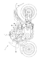
- FIG. 1 is a side view of a motorcycle according to an embodiment of the present invention.
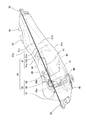
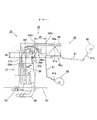
- FIG. 2 is a left side view of a fuel tank assembly.
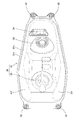
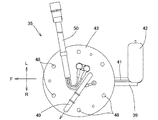
- FIG. 2 is a plan view of a fuel tank assembly.
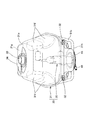
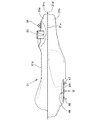
- FIG. 2 is a front view of a fuel tank assembly. It is a left view of a fuel tank. It is the VI arrow principal part enlarged view of FIG.
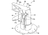
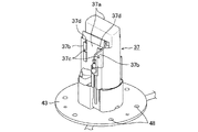
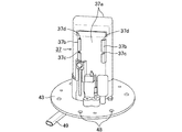
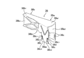
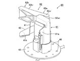
- It is a perspective view of a fuel pump unit. It is a perspective view of a fuel pump unit. It is a perspective view of a main part of a fuel pump unit. It is a perspective view of a main part of a fuel pump unit. It is a perspective view of the support part of a fuel pump unit. It is a perspective view of the support part of a fuel pump unit.
- FIG. 14 is a side view of a motorcycle to which a fuel tank assembly of still another embodiment is applied.
- FIG. 1 is a side view of a motorcycle 1 according to an embodiment of the present invention.
- a vehicle body frame 2 of the motorcycle 1 extends rearward from the head pipe 3 and a pair of left and right main frames 4 extending obliquely backward from the head pipe 3 and extending horizontally backward and extends downward.
- a pair of left and right center frames 5 and a pair of left and right down frames 6 extending downward and horizontally rearward from the head pipe 3 and connected to the lower end of the center frame 5 and upper portions of the center frame 5
- a pair of left and right extending seat rails 7 and a pair of left and right side frames 8 connected to the central portion (rear position of the engine 16) of the center frame 5 and hung around the rear of the seat rail 7 are provided.
- a front fork 11 supporting the front wheel 10 is steerably supported by the head pipe 3, and a steering handle 12 is connected to an upper portion of the front fork 11. Further, a swing arm 14 supporting the rear wheel 13 is supported by the center frame 5 via a pivot bolt 15 so as to be able to swing up and down.
- the engine 16 is supported by the main frame 4, the center frame 5 and the down frame 6.
- the power of the engine 16 is transmitted to the rear wheel 13 via the rear wheel drive sprocket 17 and the rear wheel drive chain 18.
- a helmet box 19 is formed above the engine 16 so that the helmet 20 can be stored.
- An air cleaner 21 and a battery 22 are disposed between the head pipe 3 and the helmet box 19.
- a throttle body 24 connected to an intake port 23 of the engine 16 is connected to the air cleaner 21.
- a radiator 25 is disposed in front of the engine 16 to cool the cooling water.
- An exhaust pipe 26 extending from the front of the engine 16 communicates with the muffler 27 at the rear of the vehicle body below the engine 16.
- a fuel tank assembly 30 is mounted on the upper portion of the center frame 5 and the seat rail 7 in a forward and downward direction.
- a driver's and a passenger's tandem seat 28 are attached to cover the top of the fuel tank assembly 30.
- a vehicle body frame cross member 29 connecting the left and right vehicle frames 2 is provided between the main frame 4 and the seat rail 7.
- the fuel tank assembly 30 mounted on the motorcycle 1 is shown in FIGS.
- the fuel tank assembly 30 includes a fuel tank 31 having a flat shape that is long in the front-rear direction, and mounted on the bottom plate of the fuel tank 31 inside the fuel tank 31. It consists of 35.
- the fuel tank 31 includes a tank upper half 31a and a tank lower half 31b, and flanges 31c and 31d are formed around each half, and the flanges 31c and 31d are opposed to each other.
- the upper and lower mating surfaces 31 e are seam-welded to form an integral fuel tank 31 having a cavity therein.
- a fuel inlet 33 and a breather 34 are provided on the rear upper surface of the fuel tank 31, and the fuel pump unit 35, and the fuel inlet 33 and the breather 34 are disposed in line, and the breather 34 is provided from the fuel outlet 33. It is formed rearward and upward.
- the fuel tank 31 is provided with four fuel tank attachment portions 32 at four locations, and the fuel tank 31 is a part of the seat 28 of the motorcycle 1.
- the mating surface 31 e is arranged to be inclined in the front-rear direction substantially along the seat rails 7 and attached to the center frame 5 and the seat rails 7 It has become.
- the side surface 31 f of the front of the fuel tank 31 is formed to be inclined toward the outside in the vehicle width direction from the top to the bottom, and the seat 28 is a side surface 31 f of the fuel tank 31.
- the fuel tank 31 is positioned by the inclination of the fuel tank 31 and disposed above the fuel tank 31.
- FIG. 5 shows a left side view of the fuel tank 31.
- FIG. 6 is an enlarged view of a main part of an arrow VI in FIG.
- a fuel pump unit insertion hole 44 for inserting the fuel pump unit 30 into the fuel tank 31 is formed in front of the bottom wall 31 h of the fuel tank 31.
- a flat portion 45 is formed around the fuel pump unit insertion hole 44 of the fuel tank 31, and a ring member 47 holding a plurality of bolts 46 is formed on the flat portion 45 by spot welding 47a or laser beam welding.
- the fuel pump unit 35 is welded to the fuel tank 31 via the bolt 46.
- the fuel pump unit 35 is inserted into the fuel tank 31 from the fuel pump unit insertion hole 44 on the bottom wall 31 h of the fuel tank 31 as shown in FIGS. Be placed.
- the fuel pump unit 35 is extended along the longitudinal direction of the fuel tank 31 from the upper portion of the main body portion 37 in which the fuel pump 36 is accommodated and the main body portion 37 as illustrated in FIGS. 7 to 16.
- a support 38 formed and engaged with the main body 37 and a fuel level gauge 39 supported by the support 38 are provided.
- the engaging groove forming portion 37b is integrally attached, and a notch 37c is formed in the engaging groove forming portion 37b, respectively, and a gap between the engaging groove forming portion 37b and both side walls 37a of the main body 37 is formed.
- the engagement groove 37d is configured.
- the support 38 detachably mounted on the main body 37 includes a base 38a and an extension 38b extending from the base 38a.
- the extending portion 38 b extends from the base portion 38 a along the longitudinal direction of the fuel tank 31 when the fuel pump unit 35 is mounted in the fuel tank 31 as shown in FIG. 2.
- the support portion 38 includes a top portion 38b 1 of the extending portion 38b is formed connected to flush from the top 38a 1 of the base portion 38a, base portion 38a engaging the left and right edges of the top 38a 1 at right angles to a set downward pieces 38a 2 are bent respectively, to the extension side edges of the pair of engagement pieces 38a 2, both side edges of the connection piece 38a 3 are joined together, the lower surface of the top portion 38b 1 of the extending portion 38b , while directed to the extending direction of the extending portion 38b, extending piece 38b 2 orthogonal to the top 38b 1 is formed integrally with the extended piece 38b 2 and the connecting piece 38a 3, a top 38a 1 and three reinforcing piece 38i parallel to the top portion 38b 1 is joined integrally to exist a predetermined vertical distance.
- a cutout recess 38 b 3 is formed in the lower edge adjacent to the connecting piece 38 a 3 of the extending piece 38 b 2 of the extending portion 38 b. Notches in the extending direction of the extending portion 38b of the cutout recess 38b 3 width W1 is larger than the notch width W2 in the vertical direction orthogonal to the extending direction of the extending portion 38b, the fuel tank 31
- the fuel pump unit 35 When inserting the fuel pump unit 35 from the fuel pump unit insertion hole 44 of the bottom surface 31 g and assembling it into the fuel tank 31, it is possible to assemble while preventing interference between the support portion 39 and the fuel tank 31.
- both edges in the front-rear direction of the engagement piece 38 a 2 of the base 38 a are directed downward from the notch 38 c 1 in the width direction and the tip of this notch 38 c 1 in the notch 38c 2, the insertion piece 38c is formed on the top of the insert piece 39c, the engaging claws 38d are formed to protrude outward from the surface of the engagement piece 38a 2 (see FIG. 14 ).
- Both side lower portions of the support pieces 38a 2 of the support portion 38 is inserted from above into the engaging groove 37d of the main body portion 37, press down the support portion 38 downwardly, the engagement of the support portion 38 as shown in FIG. 14
- the claw 38d engages with the notch 37c of the main body 37
- the movement of the support 38 is restricted at a predetermined position, and the support 38 is attached to the main body 37.
- a harness 38 f for holding a cord extending from the fuel level gauge 39 is formed on the upper portion of one engagement piece 38 a 2 in the base 38 a of the support portion 38.
- the upper and lower edges of the extended piece 38b 2 of the extending portion 38b is extended pieces 38b 2 are parallel to each attachment piece 38g is formed, the extended piece 38b 2
- a mounting groove 38h for mounting a fuel level gauge is constituted by the mounting piece 38g.
- the fuel level gauge 39 has a fuel level gauge main body 40, a pivot shaft 40a rotatably supported by the fuel level gauge main body 40, and a base end 41a fixed to the pivot shaft 40a.
- the float arm 41 and the float 42 fixed to the tip 41 b of the float arm 41 are provided, and the float 42 is raised or lowered according to the level of fuel in the fuel tank 31, and the float arm is moved up and down. Is pivoted to pivot the pivot shaft 40a.
- a sensor (not shown) is provided on the rotating shaft 40a, and the amount of rotation of the rotating shaft 40a is electrically detected to display an amount of remaining fuel in the fuel tank 31 to the occupant. .
- Plate-shaped insertion pieces 40b are formed above and below the fuel level gauge main body 40, and the insertion pieces 40b are inserted into the attachment grooves 38h from the extension end of the extension piece 38b 2
- the fuel level gauge 39 is attached to the extension 38.
- the downward swing limit position (indicated by the broken line in FIG. 2) indicates the positions of the float 42 and the float arm 41 when the fuel level in the fuel tank 31 is lowered and the float 42 is positioned at the lowest position.
- Solid line in FIG. 13 and the upward swing limit position (two-point dashed line) indicating the positions of the float 42 and the float arm 41 when the fuel level in the fuel tank 31 rises and the float 42 is positioned at the highest position. It is shown.
- the float 42 and the float arm 41 are positioned at the upward swing limit position, the float 42 is positioned above the mating surface 31 e of the fuel tank 31 and the tank upper half 31 a Adjacent to the upper wall 31g, the float arm 41 is provided with a support 38 extending rearward from the main body 37 along the longitudinal direction of the fuel tank 31 at a substantially central level of the height of the fuel tank 31.
- the bottom wall of the lower tank half 31b is located below the mating surface 31e of the fuel tank 31 when the float 42 is positioned at the downward swing limit position while being positioned in the same direction as the extension direction.
- a fuel level gauge 39 is disposed in the fuel tank 31 so as to be adjacent to 31 h.
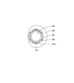
- a mounting flange 43 is fixed to the lower portion of the main body 37 as shown in FIGS.
- a discharge pipe 49 for discharging fuel from the fuel pump 36 is provided, and a bundle of electric wires such as electrical wiring for driving the fuel pump 36 and signal wiring connected to the fuel level gauge 39 50 are provided.
- the fuel supply hose 51 is connected to the discharge pipe 49, and the fuel in the fuel tank 31 is supplied to the fuel injection valve 52 connected to the intake port 23 by driving the fuel pump.
- the mounting flange 43 is provided with a plurality of bolt insertion holes 48 corresponding to the plurality of bolts 46 provided in the lower part of the fuel tank 31.
- the fuel pump unit 35 is attached to the fuel tank 31 from the fuel pump unit insertion hole 44 on the bottom of the fuel tank 31.
- the float 42 of the fuel pump unit 35, the float arm 41, the fuel level gauge 39, the support 38, the main body In the order of 37, up to the upper surface of the mounting flange 43 is inserted into the fuel tank 31, and the bolt insertion hole 48 of the mounting flange 43 is penetrated by a bolt 46 provided at the lower part of the fuel tank 31 and tightened by a nut
- the extending portion 38b of the support portion 38 of the fuel pump unit 35 is disposed such that the extending direction of the extending portion 38b is the longitudinal direction of the fuel tank 31, and the fuel pump unit 35 is attached to the fuel tank 31.
- the fuel tank assembly 30 for a vehicle has a long flat fuel tank 31 mounted on the saddle-ride type vehicle 1 in such a manner that the fuel tank 31 is inclined forward and backward in the front-rear direction.
- the support 38 and the fuel level gauge 39 are extended from the main body of the unit 35, and the float arm 41 extends along the longitudinal direction of the fuel tank 31 at a substantially central level of the fuel tank in the upward swing limit position. Because the flat tank is long in the front-rear direction of the vehicle, the operation range of the float arm 41 and the float 42 can be sufficiently secured, and the remaining amount of fuel can be detected over a wide range.
- the detection range is set.
- the fuel pump unit 35 can be compactly formed without increasing the size in the vertical direction while securing it.
- the fuel pump unit 35 by disposing the fuel pump unit 35 at the front of the fuel tank 31 which is lowered forward, it is possible to suction the fuel to the end, and the fuel pump unit can be used effectively by utilizing the space behind the fuel pump unit. 35, the fuel level gauge 39, and the float arm 41 can be arranged compactly.
- the float 42 When detecting the upper limit of the remaining amount of fuel, the float 42 is positioned above the upper and lower mating surface 31 e of the fuel tank 31 and adjacent to the upper wall 31 g of the fuel tank 31 to detect the lower limit of the remaining amount of fuel. Sometimes, the float 42 is positioned below the upper and lower mating surfaces 31e of the fuel tank 31 and adjacent to the bottom wall 31h of the fuel tank 31, so a wide detection range is secured from the top to the bottom of the fuel tank 31. can do.
- the lower edge adjacent to the connecting piece 38a 3 of the extending piece 38b 2 of the extending portion 38b is formed a recess 38b 3 notches, cut in the extending direction of the cutout recess 38b 3 extending portion 38b
- the notch width W1 is larger than the notch width W2 in the vertical direction orthogonal to the extending direction of the extending portion 38b, and the fuel pump unit 35 is inserted from the fuel pump unit insertion hole 44 on the bottom surface 31g of the fuel tank 31.
- the inclined side surface 31f of the fuel tank 31 serves as the positioning structure of the seat 28, and the seat 28 is stabilized. Can be fixed.
- the fuel supply port 33 and the breather 34 are disposed opposite to each other in the fuel tank 31 in the front-rear direction and in line with the fuel pump unit 35, the fuel supply port 33 is utilized by utilizing the space on the opposite side of the fuel pump unit 35.
- the breather 34 can be disposed, and since the breather 34 is formed rearward and above the fuel supply port 33, the gas in the fuel tank 31 can be efficiently discharged.
- a pair of front and rear L-shaped engaging groove forming portions 37b are integrally attached, and in the engaging groove forming portions 37b, notches 37c are formed, engaging groove arrangement portion 37b and the body portion is constituted engaging groove 37d by a clearance between the both sides walls 37a of 37, the supporting portion 38 the base portion 38a left and right side edges of a right angle downward one top 38a 1 of the are bent pair of engagement pieces 38a 2, respectively, at both edges in the longitudinal direction of the engaging piece 38a 2 inserts 38c is formed on top of the insert piece 39c is engaging claw 38d is engaging piece than the surface of 38a 2 is formed to protrude outward, on both sides the lower end of the supporting piece 38a 2 of the support portion 38 is inserted from above into the engaging groove 37d of the main body portion 37, the support portion 38 downwardly When the engaging claw 38d of the support portion 38 is pushed down and engaged with the notch 37c of the main body portion 37, the movement of the support
- the main body portion 37 and the support portion 38 are constituted by separate members, even when the arrangement of the fuel level gauge 39 is changed according to the shape of the fuel tank 31, By attaching the support portions 38 of different shapes while using the main body portions 37 of the same shape, it is possible to cope with the change of the arrangement, so that the cost can be reduced.
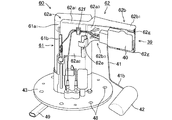
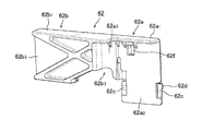
- the engagement groove forming portion 37b is integrally attached to the left and right side walls 37a of the main body portion 37 to form an engagement groove 37d, and the top 38a 1 of the base 38a. of it left and right side edges a pair of engagement pieces 38a 2 which are bent respectively at a right angle downward from was a support portion 38 provided, as shown in FIGS. 17 through 20, one side wall 61a A pair of engaging groove forming portions 61b is formed only in 1, and only on the same side as the side wall 61a 1 in which the engaging groove forming portion 61b is formed, and the main body portion 61 including the pair of engaging grooves 61d
- the fuel pump unit 60 having the support portion 62 provided with the engagement piece 62a 2 may be applied.
- the main body portion 61 of the engaging groove constituting part 61b is formed only on one side wall 61a 1, the side walls 61a 1 side engaging groove structure portion 61b is formed since only engaging piece 62a 2 are used support portion 62 provided, it is possible to reduce the weight of the fuel tank assembly 59 while maintaining the supporting rigidity.
- the fuel tank 31 is mounted on the motorcycle 1 in a forward and downward direction, and the support portion 38 of the fuel pump unit 35 and the float arm 41 at the upward swing limit position are arranged to extend rearward.
- the fuel pump assembly 30 is provided, as shown in FIG. 21, the fuel pump unit 35 of the above embodiment is disposed behind the fuel tank in the fuel tank 71 mounted on the rear end of the motorcycle 1.
- the fuel tank assembly 70 may be positioned such that the support 38 extending from the main body 39 and the float arm 41 at the upper limit position are disposed to extend forward.
- the fuel tank 71 is formed by aligning the tank upper half 71a and the tank lower half 71b with the upper and lower mating surfaces 71e, and the fuel pump unit 35 and the fuel supply port 73 are formed at the front upper portion of the fuel tank 71.
- a breather 74 is provided.
- the operating range of the float arm 81 and the float 82 can be sufficiently secured, and the remaining amount of fuel can be detected over a wide range. it can.
Landscapes
- Engineering & Computer Science (AREA)
- Mechanical Engineering (AREA)
- Chemical & Material Sciences (AREA)
- Combustion & Propulsion (AREA)
- General Engineering & Computer Science (AREA)
- Life Sciences & Earth Sciences (AREA)
- Sustainable Development (AREA)
- Sustainable Energy (AREA)
- Transportation (AREA)
- Cooling, Air Intake And Gas Exhaust, And Fuel Tank Arrangements In Propulsion Units (AREA)
- Level Indicators Using A Float (AREA)
Abstract
Description
鞍乗型車両(1)に前後方向に傾斜して搭載されるとともに前後方向に長い扁平形状の燃料タンク(31)と、該燃料タンク(31)の底壁(31h)から該燃料タンク(31)の内部に取り付けられた燃料ポンプユニット(35)とからなり、該燃料ポンプユニット(35)は、本体部(37)と、該本体部(37)の上部から前記燃料タンク(31)の長手方向に沿うように延出する支持部(38)と、該支持部(38)に支持されて延出する燃料レベルゲージ(39)とを具備し、該燃料レベルゲージ(39)は、燃料レベルゲージ本体部(40)と、該燃料レベルゲージ本体部(40)に上下に揺動可能に基端(41a)が支持されたフロートアーム(41)と、該フロートアーム(41)の先端(41b)に支持されたフロート(42)とを具備し、前記フロートアーム(41)は、前記燃料タンク(31)の長手方向に沿って延出して、前記燃料タンク(31)の高さの略中央レベルで上昇揺動限度位置を取りうることを特徴とする車両用燃料タンク組立体とする。
前記燃料ポンプユニット(35)の前記本体部(37)から延出する前記支持部(38)の延出方向と、前記上昇揺動限度位置における前記フロートアーム(41)の伸長方向とを、同方向とする。
前記燃料タンク(31)は前記鞍乗型車両(1)に前下がりに搭載され、前記燃料ポンプユニット(35)は前記燃料タンク(31)の前部の内部に配置され、前記支持部(38)、および前記上昇揺動限度位置における前記フロートアーム(41)は、後方に延出される。
前記燃料タンク(31)は前記鞍乗型車両(1)に後下がりに搭載され、前記燃料ポンプユニット(35)は前記燃料タンク(31)の後部の内部に配置され、前記支持部(38)、および前記上昇揺動限度位置における前記フロートアーム(41)は、前方に延出される。
前記燃料タンク(31)は、タンク上部半体(31a)とタンク下部半体(31b)とを、上下合わせ面(31e)で合わせて形成され、前記燃料タンク(31)内の燃料レベルの上限において、前記フロート(42)は、前記燃料タンク(31)の前記上下合わせ面(31e)より上方で、前記燃料タンク(31)の上壁(31g)に隣接して位置し、前記燃料タンク(31)の燃料レベルの下限において、前記フロート(42)は、前記燃料タンク(31)の上下合わせ面(31e)より下方で前記タンク下部半体(31b)の底壁(31h)に隣接して位置するように前記燃料レベルゲージ(39)が配置される。
前記支持部(38)の下部に切欠き凹部(38b3)が形成され、同切欠き凹部(38b3)は前記支持部(38)の延出方向における切欠き幅(W1)が、前記延出方向に直交する上下方向における切欠き幅(W2)より大きくされる。
前記燃料タンク(31)は、車両のシート(28)を下方から位置決めするべく、車幅方向外側に向けて傾斜する側面(31f)を有する。
前記燃料タンク(31)内において前後方向に、前記燃料ポンプユニット(35)と一線上に給油口(33)及びブリーザ(34)とが対向配置されると共に、前記ブリーザ(34)が前記給油口(33)より後方かつ上方に形成される。
前記本体部(37)に係合溝(37d)が形成されると共に、前記係合溝(38d)を構成する係合溝形成部(37b)に切欠き(37c)が形成され、前記支持部(38)に係合片(38a2)が形成されると共に、前記係合片(38a2)に係合爪(38e)が形成され、前記係合溝(37d)に前記係合片(38a2)が挿入され、前記係合爪(38e)が前記切欠き(37c)に係合されることにより、前記支持部(37)が所定位置にて移動規制され、前記本体部(37)と前記支持部(38)とが相互に係合して固定される。
前記支持部(38)には、前記本体部(37)を跨いで一対の前記係合片(38a2)が設けられており、該係合片(38a2)が前記本体部(37)の両側に設けられた2組の前記係合溝(37d)に係合されることにより固定される。
燃料タンク組立体30は、自動二輪車1に前下がりに傾斜して搭載される前後方向に長い扁平形状の燃料タンク31と、燃料タンク31の底板上において燃料タンク31の内部に取付けられる燃料ポンプユニット35とからなっている。
70…燃料タンク組立体、71…燃料タンク、73…給油口、74…ブリーザ。
Claims (10)
- 鞍乗型車両(1)に前後方向に傾斜して搭載されるとともに前後方向に長い扁平形状の燃料タンク(31)と、
該燃料タンク(31)の底壁(31h)から該燃料タンク(31)の内部に取り付けられた燃料ポンプユニット(35)とからなり、
該燃料ポンプユニット(35)は、本体部(37)と、該本体部(37)の上部から前記燃料タンク(31)の長手方向に沿うように延出する支持部(38)と、該支持部(38)に支持されて延出する燃料レベルゲージ(39)とを具備し、
該燃料レベルゲージ(39)は、燃料レベルゲージ本体部(40)と、該燃料レベルゲージ本体部(40)に上下に揺動可能に基端(41a)が支持されたフロートアーム(41)と、該フロートアーム(41)の先端(41b)に支持されたフロート(42)とを具備し、
前記フロートアーム(41)は、前記燃料タンク(31)の長手方向に沿って延出して、前記燃料タンク(31)の高さの略中央レベルで上昇揺動限度位置を取りうることを特徴とする車両用燃料タンク組立体。 - 前記燃料ポンプユニット(35)の前記本体部(37)から延出する前記支持部(38)の延出方向と、前記上昇揺動限度位置における前記フロートアーム(41)の伸長方向とが、同方向であることを特徴とする請求項1に記載の車両用燃料タンク組立体。
- 前記燃料タンク(31)は前記鞍乗型車両(1)に前下がりに搭載され、前記燃料ポンプユニット(35)は前記燃料タンク(31)の前部の内部に配置され、
前記支持部(38)、および前記上昇揺動限度位置における前記フロートアーム(41)は、後方に延出することを特徴とする請求項1又は請求項2に記載の車両用燃料タンク組立体。 - 前記燃料タンク(71)は前記鞍乗型車両(1)に後下がりに搭載され、前記燃料ポンプユニット(75)は前記燃料タンク(71)の後部の内部に配置され、
前記支持部(78)、および前記上昇揺動限度位置における前記フロートアーム(81)は、前方に延出することを特徴とする請求項1又は請求項2に記載の車両用燃料タンク組立体。 - 前記燃料タンク(31)は、タンク上部半体(31a)とタンク下部半体(31b)とを、上下合わせ面(31e)で合わせて形成され、
前記燃料タンク(31)内の燃料レベルの上限において、前記フロート(42)は、前記燃料タンク(31)の前記上下合わせ面(31e)より上方で、前記燃料タンク(31)の上壁(31g)に隣接して位置し、前記燃料タンク(31)の燃料レベルの下限において、前記フロート(42)は、前記燃料タンク(31)の上下合わせ面(31e)より下方で前記タンク下部半体(31b)の底壁(31h)に隣接して位置するように前記燃料レベルゲージ(39)が配置されていることを特徴とする請求項1ないし請求項4のいずれかに記載の車両用燃料タンク組立体。 - 前記支持部(38)の下部に切欠き凹部(38b3)が形成され、同切欠き凹部(38b3)は前記支持部(38)の延出方向における切欠き幅(W1)が、前記延出方向に直交する上下方向における切欠き幅(W2)より大きいことを特徴とする請求項1ないし請求項5のいずれかに記載の車両用燃料タンク組立体。
- 前記燃料タンク(31)は、車両のシート(28)を下方から位置決めするべく、車幅方向外側に向けて傾斜する側面(31f)を有することを特徴とする請求項1ないし請求項6のいずれかに記載の車両用燃料タンク組立体。
- 前記燃料タンク(31)内において前後方向に、前記燃料ポンプユニット(35)と一線上に給油口(33)及びブリーザ(34)とが対向配置されると共に、前記ブリーザ(34)が前記給油口(33)より後方かつ上方に形成されることを特徴とする請求項1ないし請求項7のいずれかに記載の車両用燃料タンク組立体。
- 前記本体部(37)に係合溝(37d)が形成されると共に、前記係合溝(38d)を構成する係合溝形成部(37b)に切欠き(37c)が形成され、
前記支持部(38)に係合片(38a2)が形成されると共に、前記係合片(38a2)に係合爪(38e)が形成され、
前記係合溝(37d)に前記係合片(38a2)が挿入され、前記係合爪(38e)が前記切欠き(37c)に係合されることにより、前記支持部(37)が所定位置にて移動規制され、前記本体部(37)と前記支持部(38)とが相互に係合して固定されることを特徴とする請求項1ないし請求項8のいずれかに記載の車両用燃料タンク組立体。 - 前記支持部(38)には、前記本体部(37)を跨いで一対の前記係合片(38a2)が設けられており、該係合片(38a2)が前記本体部(37)の両側に設けられた2組の前記係合溝(37d)に係合されることにより固定されることを特徴とする請求項9に記載の車両用燃料タンク組立体。
Priority Applications (4)
| Application Number | Priority Date | Filing Date | Title |
|---|---|---|---|
| US13/808,697 US8881854B2 (en) | 2010-07-30 | 2011-07-19 | Fuel tank assembly of vehicle |
| JP2012526433A JP5352008B2 (ja) | 2010-07-30 | 2011-07-19 | 車両用燃料タンク組立体 |
| EP11812311.6A EP2599700B1 (en) | 2010-07-30 | 2011-07-19 | Saddle-riding type vehicle |
| BR112013002309A BR112013002309B1 (pt) | 2010-07-30 | 2011-07-19 | montagem de tanque de combustível de veículo |
Applications Claiming Priority (2)
| Application Number | Priority Date | Filing Date | Title |
|---|---|---|---|
| JP2010-171368 | 2010-07-30 | ||
| JP2010171368 | 2010-07-30 |
Publications (1)
| Publication Number | Publication Date |
|---|---|
| WO2012014719A1 true WO2012014719A1 (ja) | 2012-02-02 |
Family
ID=45529935
Family Applications (1)
| Application Number | Title | Priority Date | Filing Date |
|---|---|---|---|
| PCT/JP2011/066350 Ceased WO2012014719A1 (ja) | 2010-07-30 | 2011-07-19 | 車両用燃料タンク組立体 |
Country Status (5)
| Country | Link |
|---|---|
| US (1) | US8881854B2 (ja) |
| EP (1) | EP2599700B1 (ja) |
| JP (1) | JP5352008B2 (ja) |
| BR (1) | BR112013002309B1 (ja) |
| WO (1) | WO2012014719A1 (ja) |
Cited By (7)
| Publication number | Priority date | Publication date | Assignee | Title |
|---|---|---|---|---|
| EP2669167A1 (en) * | 2012-05-28 | 2013-12-04 | Yamaha Hatsudoki Kabushiki Kaisha | Fuel tank and saddle riding type vehicle |
| JP2015071986A (ja) * | 2013-10-03 | 2015-04-16 | スズキ株式会社 | 燃料ゲージ付きセパレータ装置 |
| JP2018024310A (ja) * | 2016-08-09 | 2018-02-15 | 本田技研工業株式会社 | 鞍乗型車両の燃料タンク |
| JP2019183657A (ja) * | 2018-04-02 | 2019-10-24 | 愛三工業株式会社 | 液面検出装置 |
| CN113165715A (zh) * | 2018-12-13 | 2021-07-23 | 本田技研工业株式会社 | 跨骑型车辆 |
| JP2022074232A (ja) * | 2020-11-04 | 2022-05-18 | 三菱電機株式会社 | 燃料供給装置 |
| CN115667062A (zh) * | 2020-05-22 | 2023-01-31 | Tvs电机股份有限公司 | 具有存储结构组件的鞍座型车辆 |
Families Citing this family (9)
| Publication number | Priority date | Publication date | Assignee | Title |
|---|---|---|---|---|
| JP3287454B2 (ja) * | 1997-08-22 | 2002-06-04 | ジョンソン コントロールズ オートモーティブ システムズ株式会社 | 両側リクライニング装置 |
| JP5352008B2 (ja) * | 2010-07-30 | 2013-11-27 | 本田技研工業株式会社 | 車両用燃料タンク組立体 |
| JP5530293B2 (ja) * | 2010-07-30 | 2014-06-25 | 本田技研工業株式会社 | 自動二輪車 |
| JP2015068312A (ja) * | 2013-09-30 | 2015-04-13 | 本田技研工業株式会社 | 燃料ポンプ取付け構造 |
| US10300990B2 (en) * | 2014-08-29 | 2019-05-28 | Bombardier Recreational Products Inc. | Snowmobile fuel tank |
| JP6170517B2 (ja) * | 2015-03-26 | 2017-07-26 | 本田技研工業株式会社 | 鞍乗り型車両の燃料タンク |
| JP6649971B2 (ja) * | 2018-02-13 | 2020-02-19 | 本田技研工業株式会社 | 鞍乗り型車両 |
| JP6522200B1 (ja) * | 2018-05-09 | 2019-05-29 | 三菱電機株式会社 | 燃料供給装置 |
| DE102019112741B3 (de) * | 2019-05-15 | 2020-05-20 | Ktm Ag | Kraftstofftankanordnung mit mindestens zwei getrennten Tankkörpern |
Citations (6)
| Publication number | Priority date | Publication date | Assignee | Title |
|---|---|---|---|---|
| JPH0364316B2 (ja) | 1987-09-25 | 1991-10-04 | Nissha Printing | |
| JP2003112677A (ja) * | 2001-10-05 | 2003-04-15 | Yamaha Motor Co Ltd | 自動二輪車の燃料系配置構造 |
| JP2005138712A (ja) * | 2003-11-06 | 2005-06-02 | Suzuki Motor Corp | スクーター型自動二輪車の燃料供給装置 |
| JP2005343212A (ja) * | 2004-05-31 | 2005-12-15 | Yamaha Motor Co Ltd | 車両 |
| JP2007118628A (ja) * | 2005-10-24 | 2007-05-17 | Yamaha Motor Co Ltd | 鞍乗型車両 |
| JP2007321608A (ja) | 2006-05-31 | 2007-12-13 | Honda Motor Co Ltd | 燃料配管構造 |
Family Cites Families (40)
| Publication number | Priority date | Publication date | Assignee | Title |
|---|---|---|---|---|
| JPH0215752Y2 (ja) * | 1981-04-28 | 1990-04-26 | ||
| US4461489A (en) * | 1981-09-03 | 1984-07-24 | Honda Giken Kogyo Kabushiki Kaisha | Body frame with a liquid tank secured integrally thereto for a motorcycle |
| US4492250A (en) * | 1982-04-07 | 1985-01-08 | Honda Giken Kogyo Kabushiki Kaisha | Fuel tank for motor vehicles |
| US4799569A (en) * | 1985-08-23 | 1989-01-24 | Honda Giken Kogyo Kabushiki Kaisha | Motorcycle |
| US4951774A (en) * | 1989-01-06 | 1990-08-28 | Buell Motor Company, Inc. | Combination motorcycle frame and fuel tank |
| US5147077A (en) | 1990-01-25 | 1992-09-15 | Suzuki Kabushiki Kaisha | Storage box compartment means for a motorcycle |
| JP3064316B2 (ja) * | 1990-01-30 | 2000-07-12 | スズキ株式会社 | 自動2輪車の燃料タンク装置 |
| US5542706A (en) * | 1995-01-11 | 1996-08-06 | Safety Engineering Associates, Inc. | Motor vehicle fuel system |
| DE69729166T2 (de) * | 1996-12-20 | 2005-05-04 | Suzuki K.K., Hamamatsu | Kraftstofftankeinrichtung für Motorrad |
| JP3772630B2 (ja) * | 2000-03-02 | 2006-05-10 | スズキ株式会社 | 自動二輪車の燃料タンク装置 |
| JP3879392B2 (ja) * | 2000-11-29 | 2007-02-14 | スズキ株式会社 | 自動二輪車の燃料タンク |
| JP4354135B2 (ja) * | 2001-08-31 | 2009-10-28 | 本田技研工業株式会社 | 自動2輪車用燃料タンクの取付構造 |
| US6758497B2 (en) * | 2002-04-29 | 2004-07-06 | Arctic Cat Inc. | Fuel tank for a straddle-mounted vehicle |
| TWM241304U (en) * | 2002-12-03 | 2004-08-21 | Mclee Co Ltd | Fuel tank for walk-assisting bike |
| US6857661B2 (en) * | 2003-02-12 | 2005-02-22 | American Ironhorse Motorcycle Company | Partitioned fuel tank and fuel delivery system |
| US6896293B2 (en) * | 2003-07-11 | 2005-05-24 | Harley-Davidson Motor Company Group, Inc. | Motorcycle fuel tank mounting arrangement |
| US7422243B2 (en) * | 2003-07-29 | 2008-09-09 | Honda Motor Co., Ltd. | Structure of fuel pump installation area for two-wheeled vehicle |
| JP4347015B2 (ja) * | 2003-10-10 | 2009-10-21 | ヤマハ発動機株式会社 | 鞍乗り型車両用フューエルタンク配設構造 |
| US7992901B2 (en) * | 2004-01-27 | 2011-08-09 | Yamaha Hatsudoki Kabushiki Kaisha | Straddling type of vehicle |
| JP4559165B2 (ja) * | 2004-09-06 | 2010-10-06 | 本田技研工業株式会社 | 鞍乗型車両の燃料タンク取付構造 |
| JP4340898B2 (ja) | 2004-11-17 | 2009-10-07 | 株式会社デンソー | 燃料供給装置 |
| US7390023B2 (en) * | 2004-11-19 | 2008-06-24 | Yamaha Hatsudoki Kabushiki Kaisha | Motorcycle fuel tank |
| CN100513767C (zh) | 2004-12-09 | 2009-07-15 | 株式会社电装 | 供油装置 |
| US7533904B2 (en) * | 2005-07-05 | 2009-05-19 | Yamaha Hatsudoki Kabushiki Kaisha | Saddle-riding type vehicle with fuel pump |
| JP2007118627A (ja) * | 2005-10-24 | 2007-05-17 | Yamaha Motor Co Ltd | 燃料タンクアセンブリ及び当該燃料タンクアセンブリを備えた鞍乗型車両 |
| JP4725398B2 (ja) * | 2006-04-12 | 2011-07-13 | スズキ株式会社 | 自動二輪車の燃料タンク |
| US7712564B2 (en) * | 2006-10-09 | 2010-05-11 | Harley-Davidson Motor Company Group, LLC | Air box for a motorcycle |
| JP2009161016A (ja) * | 2007-12-28 | 2009-07-23 | Yamaha Motor Co Ltd | 鞍乗型車両 |
| JP5160247B2 (ja) * | 2008-01-17 | 2013-03-13 | 本田技研工業株式会社 | 燃料タンク及び燃料ポンプ取付構造 |
| JP5147456B2 (ja) * | 2008-02-29 | 2013-02-20 | ヤマハ発動機株式会社 | 自動二輪車 |
| JP5235089B2 (ja) * | 2008-03-27 | 2013-07-10 | 本田技研工業株式会社 | 燃料ポンプ取付構造 |
| JP2010058758A (ja) * | 2008-09-05 | 2010-03-18 | Yamaha Motor Co Ltd | 鞍乗型四輪車両 |
| JP4890532B2 (ja) * | 2008-12-26 | 2012-03-07 | 本田技研工業株式会社 | 鞍乗型車両 |
| JP2010188758A (ja) * | 2009-02-16 | 2010-09-02 | Yamaha Motor Co Ltd | 自動二輪車 |
| JP5315109B2 (ja) * | 2009-03-30 | 2013-10-16 | 本田技研工業株式会社 | 車両のキャニスタの大気開放構造 |
| JP5390978B2 (ja) * | 2009-07-31 | 2014-01-15 | 本田技研工業株式会社 | 自動二輪車の蒸発燃料処理装置 |
| JP5520623B2 (ja) * | 2010-01-29 | 2014-06-11 | 本田技研工業株式会社 | 燃料供給装置 |
| US8616403B2 (en) * | 2010-03-23 | 2013-12-31 | Honda Motor Co., Ltd. | Fuel filler port device of fuel tank for straddled vehicle |
| JP5436398B2 (ja) * | 2010-03-26 | 2014-03-05 | 本田技研工業株式会社 | 車両用燃料タンク |
| JP5352008B2 (ja) * | 2010-07-30 | 2013-11-27 | 本田技研工業株式会社 | 車両用燃料タンク組立体 |
-
2011
- 2011-07-19 JP JP2012526433A patent/JP5352008B2/ja not_active Expired - Fee Related
- 2011-07-19 EP EP11812311.6A patent/EP2599700B1/en not_active Not-in-force
- 2011-07-19 WO PCT/JP2011/066350 patent/WO2012014719A1/ja not_active Ceased
- 2011-07-19 BR BR112013002309A patent/BR112013002309B1/pt not_active IP Right Cessation
- 2011-07-19 US US13/808,697 patent/US8881854B2/en not_active Expired - Fee Related
Patent Citations (6)
| Publication number | Priority date | Publication date | Assignee | Title |
|---|---|---|---|---|
| JPH0364316B2 (ja) | 1987-09-25 | 1991-10-04 | Nissha Printing | |
| JP2003112677A (ja) * | 2001-10-05 | 2003-04-15 | Yamaha Motor Co Ltd | 自動二輪車の燃料系配置構造 |
| JP2005138712A (ja) * | 2003-11-06 | 2005-06-02 | Suzuki Motor Corp | スクーター型自動二輪車の燃料供給装置 |
| JP2005343212A (ja) * | 2004-05-31 | 2005-12-15 | Yamaha Motor Co Ltd | 車両 |
| JP2007118628A (ja) * | 2005-10-24 | 2007-05-17 | Yamaha Motor Co Ltd | 鞍乗型車両 |
| JP2007321608A (ja) | 2006-05-31 | 2007-12-13 | Honda Motor Co Ltd | 燃料配管構造 |
Non-Patent Citations (1)
| Title |
|---|
| See also references of EP2599700A4 |
Cited By (8)
| Publication number | Priority date | Publication date | Assignee | Title |
|---|---|---|---|---|
| EP2669167A1 (en) * | 2012-05-28 | 2013-12-04 | Yamaha Hatsudoki Kabushiki Kaisha | Fuel tank and saddle riding type vehicle |
| JP2015071986A (ja) * | 2013-10-03 | 2015-04-16 | スズキ株式会社 | 燃料ゲージ付きセパレータ装置 |
| JP2018024310A (ja) * | 2016-08-09 | 2018-02-15 | 本田技研工業株式会社 | 鞍乗型車両の燃料タンク |
| JP2019183657A (ja) * | 2018-04-02 | 2019-10-24 | 愛三工業株式会社 | 液面検出装置 |
| CN113165715A (zh) * | 2018-12-13 | 2021-07-23 | 本田技研工业株式会社 | 跨骑型车辆 |
| CN113165715B (zh) * | 2018-12-13 | 2022-04-01 | 本田技研工业株式会社 | 跨骑型车辆 |
| CN115667062A (zh) * | 2020-05-22 | 2023-01-31 | Tvs电机股份有限公司 | 具有存储结构组件的鞍座型车辆 |
| JP2022074232A (ja) * | 2020-11-04 | 2022-05-18 | 三菱電機株式会社 | 燃料供給装置 |
Also Published As
| Publication number | Publication date |
|---|---|
| EP2599700A4 (en) | 2014-01-15 |
| BR112013002309A2 (pt) | 2016-05-24 |
| BR112013002309B1 (pt) | 2019-09-03 |
| JPWO2012014719A1 (ja) | 2013-09-12 |
| EP2599700A1 (en) | 2013-06-05 |
| US8881854B2 (en) | 2014-11-11 |
| JP5352008B2 (ja) | 2013-11-27 |
| US20130105234A1 (en) | 2013-05-02 |
| EP2599700B1 (en) | 2015-04-08 |
Similar Documents
| Publication | Publication Date | Title |
|---|---|---|
| WO2012014719A1 (ja) | 車両用燃料タンク組立体 | |
| JP5399168B2 (ja) | 自動二輪車 | |
| EP2077224B1 (en) | Motorcycle | |
| JP5362694B2 (ja) | 鞍乗型車両 | |
| JP6208647B2 (ja) | 鞍乗り型車両の後部燃料タンク支持構造 | |
| JP5142781B2 (ja) | 自動二輪車 | |
| JP2006088892A (ja) | 鞍乗型車両 | |
| JP6086889B2 (ja) | 後部燃料タンク | |
| JP2006088895A (ja) | 鞍乗型車両 | |
| JP2006088894A (ja) | 鞍乗型車両 | |
| JP2016193647A (ja) | 鞍乗型車両 | |
| JP4996521B2 (ja) | 自動二輪車のラジエータリザーブタンク配置構造 | |
| JP5645506B2 (ja) | 燃料供給装置 | |
| JP5323533B2 (ja) | 鞍乗り型車両 | |
| JP5782993B2 (ja) | 自動二輪車の燃料タンク | |
| CN101152838A (zh) | 用于鞍形座骑乘式车辆的空气滤清器布置结构和电池支撑结构 | |
| JPWO2018159014A1 (ja) | 鞍乗り型車両のメーター取付構造 | |
| JP6664500B2 (ja) | 鞍乗型車両のバッテリケース | |
| JP2022065831A (ja) | 鞍乗型車両の車体構造 | |
| JP2013203092A (ja) | 自動二輪車 | |
| CN100497074C (zh) | 燃料供应装置 | |
| CN102285395B (zh) | 跨骑型车辆 | |
| CN111433115B (zh) | 跨骑型车辆 | |
| JP2004268840A (ja) | 鞍乗型車両のヘルメット収納構造 | |
| JP5919354B2 (ja) | 鞍乗型車両の車体カバー押え構造 |
Legal Events
| Date | Code | Title | Description |
|---|---|---|---|
| 121 | Ep: the epo has been informed by wipo that ep was designated in this application |
Ref document number: 11812311 Country of ref document: EP Kind code of ref document: A1 |
|
| WWE | Wipo information: entry into national phase |
Ref document number: 2012526433 Country of ref document: JP |
|
| WWE | Wipo information: entry into national phase |
Ref document number: 2011812311 Country of ref document: EP |
|
| WWE | Wipo information: entry into national phase |
Ref document number: 13808697 Country of ref document: US |
|
| NENP | Non-entry into the national phase |
Ref country code: DE |
|
| REG | Reference to national code |
Ref country code: BR Ref legal event code: B01A Ref document number: 112013002309 Country of ref document: BR |
|
| ENP | Entry into the national phase |
Ref document number: 112013002309 Country of ref document: BR Kind code of ref document: A2 Effective date: 20130130 |