WO2012017606A1 - 電気掃除機 - Google Patents
電気掃除機 Download PDFInfo
- Publication number
- WO2012017606A1 WO2012017606A1 PCT/JP2011/003997 JP2011003997W WO2012017606A1 WO 2012017606 A1 WO2012017606 A1 WO 2012017606A1 JP 2011003997 W JP2011003997 W JP 2011003997W WO 2012017606 A1 WO2012017606 A1 WO 2012017606A1
- Authority
- WO
- WIPO (PCT)
- Prior art keywords
- dust
- drive
- filter
- vacuum cleaner
- dust remover
- Prior art date
- Legal status (The legal status is an assumption and is not a legal conclusion. Google has not performed a legal analysis and makes no representation as to the accuracy of the status listed.)
- Ceased
Links
Images


Classifications
-
- A—HUMAN NECESSITIES
- A47—FURNITURE; DOMESTIC ARTICLES OR APPLIANCES; COFFEE MILLS; SPICE MILLS; SUCTION CLEANERS IN GENERAL
- A47L—DOMESTIC WASHING OR CLEANING; SUCTION CLEANERS IN GENERAL
- A47L9/00—Details or accessories of suction cleaners, e.g. mechanical means for controlling the suction or for effecting pulsating action; Storing devices specially adapted to suction cleaners or parts thereof; Carrying-vehicles specially adapted for suction cleaners
- A47L9/20—Means for cleaning filters
-
- A—HUMAN NECESSITIES
- A47—FURNITURE; DOMESTIC ARTICLES OR APPLIANCES; COFFEE MILLS; SPICE MILLS; SUCTION CLEANERS IN GENERAL
- A47L—DOMESTIC WASHING OR CLEANING; SUCTION CLEANERS IN GENERAL
- A47L9/00—Details or accessories of suction cleaners, e.g. mechanical means for controlling the suction or for effecting pulsating action; Storing devices specially adapted to suction cleaners or parts thereof; Carrying-vehicles specially adapted for suction cleaners
- A47L9/0081—Means for exhaust-air diffusion; Means for sound or vibration damping
-
- A—HUMAN NECESSITIES
- A47—FURNITURE; DOMESTIC ARTICLES OR APPLIANCES; COFFEE MILLS; SPICE MILLS; SUCTION CLEANERS IN GENERAL
- A47L—DOMESTIC WASHING OR CLEANING; SUCTION CLEANERS IN GENERAL
- A47L9/00—Details or accessories of suction cleaners, e.g. mechanical means for controlling the suction or for effecting pulsating action; Storing devices specially adapted to suction cleaners or parts thereof; Carrying-vehicles specially adapted for suction cleaners
- A47L9/10—Filters; Dust separators; Dust removal; Automatic exchange of filters
- A47L9/12—Dry filters
- A47L9/122—Dry filters flat
-
- B—PERFORMING OPERATIONS; TRANSPORTING
- B01—PHYSICAL OR CHEMICAL PROCESSES OR APPARATUS IN GENERAL
- B01D—SEPARATION
- B01D46/00—Filters or filtering processes specially modified for separating dispersed particles from gases or vapours
- B01D46/10—Particle separators, e.g. dust precipitators, using filter plates, sheets or pads having plane surfaces
-
- B—PERFORMING OPERATIONS; TRANSPORTING
- B01—PHYSICAL OR CHEMICAL PROCESSES OR APPARATUS IN GENERAL
- B01D—SEPARATION
- B01D46/00—Filters or filtering processes specially modified for separating dispersed particles from gases or vapours
- B01D46/66—Regeneration of the filtering material or filter elements inside the filter
- B01D46/74—Regeneration of the filtering material or filter elements inside the filter by forces created by movement of the filter element
- B01D46/76—Regeneration of the filtering material or filter elements inside the filter by forces created by movement of the filter element involving vibrations
Definitions
- the present invention relates to a vacuum cleaner provided with a filter for filtering dust.
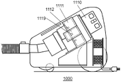
- FIG. 13 is a schematic view showing a schematic configuration of a conventional vacuum cleaner 1000.
- FIG. 14 is a perspective view showing the configuration of the filter device 1111 in the conventional vacuum cleaner 1000. As shown in FIG.
- the vacuum cleaner 1000 includes a filter device 1111 that supplements the dust sucked by the electric blower 1110, and a vibrator 1112 that vibrates the filter device 1111. Before or after driving the electric blower 1110, the filter device 111 is vibrated by the vibrator 1112 to remove dust captured by the filter device 1111.
- the filter device 1111 has a rectangular frame 1113, a sheet 1116, and a vibration transmission member 1117.
- the sheet 1116 is provided in the frame 1113 and is bent in a wave shape to form a plurality of projections 1114 and recesses 1115.
- the vibration transmitting member 1117 transmits the vibration of the vibrator 1112 to the sheet 1116.
- the vibrator 1112 has a vibration motor inside and is juxtaposed to the filter device 1111.
- the vibration transfer member 1117 includes a plurality of claws 1118 fitted in the plurality of recesses 1115 of the sheet 1116, and a transfer protrusion 1119 directly receiving the vibration from the vibrator 1112.
- the vibration of the vibrator 1112 is transmitted from the transmission protrusion 1119 to the vibration transmission member 1117, and the vibration is transmitted from the claw portion 1118 to the sheet 1116. Thereby, the dust captured by the sheet 1116 can be removed.
- the vibrator 1112 is disposed in parallel with the filter device 1111. For this reason, the vibration of the vibrator 1112 causes the entire filter device 1111 to vibrate at the same time as the transmission protrusion 1119 is vibrated. Therefore, the vibrational energy of the vibrator 1112 is diffused not only to the filter device 1111 but also to the entire vacuum cleaner 1000 supporting the filter device 1111.
- the vibration from the vibrator 1112 is transmitted to the transmission protrusion 1119 of the vibration transmission member 1117, vibrates the claw portion 1118, and is transmitted to the sheet 1116. Therefore, the transmission loss until the vibration of the vibrator 1112 is transmitted to the sheet 1116 is large, and the vibration is attenuated.
- the transmission projection 1119 of the vibration transmission member 1117 directly receives the vibration of the vibrator 1112, a collision sound is generated and a noise is generated.
- the present invention provides a vacuum cleaner which removes dust attached to a filter with low noise and high efficiency.
- the vacuum cleaner according to the present invention comprises an electric blower, a filter for supplementing dust attracted by the electric blower, and a dust removing unit for removing dust attached to the filter.
- the dust removing unit has a restricting unit for linear driving, and a driving unit that reciprocates, and a dust remover that is disposed close to the filter and moves in substantially the same direction as the direction of the reciprocating driving of the driving unit.
- an elastic portion for transmitting the reciprocating drive of the drive portion to the dust collector via the elastic body. The amplitude of the reciprocation of the dust collector is increased by the resonance caused by the elastic portion to vibrate the filter.
- FIG. 1 is a side view showing an appearance of a vacuum cleaner according to a first embodiment of the present invention.
- FIG. 2 is sectional drawing which shows a structure of the main part of the main part of the vacuum cleaner in the 1st Embodiment of this invention.
- FIG. 3 is a perspective view which shows the structure of the filter and dust removal part of the vacuum cleaner in the 1st Embodiment of this invention.
- FIG. 4A is a plan view showing the configuration of the filter and the dust removing unit of the vacuum cleaner according to the first embodiment of the present invention.
- FIG. 4B is a cross-sectional view showing the configuration of the filter and the dust removing unit of the vacuum cleaner according to the first embodiment of the present invention.
- FIG. 4A is a plan view showing the configuration of the filter and the dust removing unit of the vacuum cleaner according to the first embodiment of the present invention.
- FIG. 4B is a cross-sectional view showing the configuration of the filter and the dust removing unit of the vacuum cleaner according to the first embodiment of
- FIG. 4C is a cross-sectional view showing the configuration of the filter and the dust removing unit of the vacuum cleaner according to the first embodiment of the present invention.
- FIG. 5 is a view for explaining the gap C between the claw portion of the dust remover and the membrane of the filter in the vacuum cleaner according to the first embodiment of the present invention.
- FIG. 6 is a characteristic diagram showing the time change of the stroke of the drive unit of the vacuum cleaner and the dust remover according to the first embodiment of the present invention.
- FIG. 7: is a figure which shows the vibration characteristic of the dust remover of the vacuum cleaner in the 1st Embodiment of this invention.
- FIG. 8 is a partial cross-sectional view showing a configuration of a filter and a dust removing unit in a vacuum cleaner according to a second embodiment of the present invention.
- FIG. 9 is a cross-sectional view showing a configuration of a filter and a dust removing unit of a vacuum cleaner according to a third embodiment of the present invention.
- FIG. 10 is a perspective view which shows the structure of the dust remover of the vacuum cleaner which concerns on the 3rd Embodiment of this invention.
- FIG. 11 is a perspective view showing the configuration of the filter and the dust removing unit of the vacuum cleaner according to the fourth embodiment of the present invention.
- FIG. 12A is a front view showing a configuration of a filter and a dust removing unit of a vacuum cleaner according to a fourth embodiment of the present invention.
- FIG. 12B is a cross-sectional view showing the configuration of the filter and the dust removing unit of the vacuum cleaner according to the fourth embodiment of the present invention.
- FIG. 12C is a cross-sectional view showing the configuration of the filter and the dust removing unit of the vacuum cleaner according to the fourth embodiment of the present invention.
- FIG. 13 is a schematic view showing a schematic configuration of a conventional vacuum cleaner.
- FIG. 14 is a perspective view showing a configuration of a filter device in a conventional vacuum cleaner.
- FIG. 1 is a side view showing an appearance of a vacuum cleaner 49 according to a first embodiment of the present invention.
- FIG. 2 is sectional drawing which shows the structure of the main part of the main body of the same vacuum cleaner 49.
- FIG. 3 is a perspective view showing the configuration of the filter 40 and the dust removing unit 45 of the vacuum cleaner 49.
- FIG. 4A is a plan view showing the configuration of the filter 40 and the dust removing unit 45 of the vacuum cleaner 49.
- FIG. FIG. 4B is a cross-sectional view showing the configuration of the filter 40 and the dust removing unit 45 of the vacuum cleaner 49.
- FIG. 4C is a cross-sectional view showing the configuration of the filter 40 and the dust removing unit 45 of the vacuum cleaner 49.
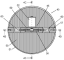
- the wheel 3 and the caster 4 are attached to the exterior of the vacuum cleaner main body 1 of the vacuum cleaner 49, and the vacuum cleaner main body 1 can freely move on the floor surface.
- a suction hose 7 and an extension pipe 8 are sequentially connected to a suction port 6 provided below the dust collection case 5 installation portion, and a suction tool 9 is attached to the tip of the extension pipe 8.
- an electric blower 21 is built in the cleaner body 1.
- the dust collection case 5 is disposed detachably with respect to the cleaner body 1 via a partition wall 26 having a vent 22.
- the dust collection case 5 introduces air containing suctioned dust, centrifugally separates and accumulates dust, and filters fine dust.
- the filtered air is exhausted from an exhaust outlet (not shown) downstream of the electric blower 21 (cyclone type vacuum cleaner).
- the dust collection case 5 has a suction port 30 and is provided with a hollow cylindrical dust collection box 31 disposed on the lower side, an exhaust port 32, and a dust collection lid 33 disposed on the upper side. There is. In the state where the dust collection case 5 is mounted on the cleaner body 1, the intake port 30 and the suction port 6 of the cleaner body 1 communicate with each other, and the exhaust port 32 and the vent 22 of the cleaner body 1 communicate with each other. Is configured as.
- the dust collection box 31 has an inner case 34 in the form of hollow cylinders of different diameters and hollow cones stacked in multiple stages.
- the filter housing case 35, the inclined cylinder A36, the primary filter 37, the inclined cylinder B38, and the fine dust cylinder 39 are connected in series in order from the top.
- the filter housing case 35 has a hollow cylindrical shape, and the filter 40 is housed inside, and the outer periphery is housed along the upper end portion of the inner surface of the dust collection box 31.
- a seal member (not shown) closes the gap between the outer surface of the filter housing case 35 and the inner surface of the dust collection box 31.
- the inclined cylinder A36 has a hollow conical shape, and when removing dust captured by the filter 40, an inclined surface for guiding dust falling from the filter 40 to the primary filter 37, the inclined cylinder B38 and the dust cylinder 39 is used. It has inside.
- the primary filter 37 has a cylindrical shape having minute through holes on the entire surface, and by passing air from the outer periphery of the cylinder to the inside of the cylinder, dust in relatively large size, such as dust, hair, etc. Filter out (coarse dust).
- the inclined cylinder B 38 has a hollow conical shape like the inclined cylinder A 36, and internally has a slope for guiding dust falling from the filter 40 to the fine dust cylinder 39.
- the fine dust cylinder 39 is in the shape of a hollow cylinder, and the dust guided from the inclined cylinder B38 is used to store therein the dust.
- a packing 41 is provided on the bottom inner surface of the dust collection box 31 to seal between the bottom of the fine dust cylinder 39 and the bottom.
- the intake port 30 is opened so that the suctioned air current flows in the tangential direction of the inner surface of the dust collection box 31.
- the suction air flow rotates a flow path formed by a gap between the outer surface of each of the inclined cylinder A 36, the primary filter 37, the inclined cylinder B 38 and the fine dust cylinder 39 and the inner surface of the dust collection box 31.
- the suction air flow is finally sucked into the cylinder by the primary filter 37 and flows toward the filter 40.
- Dust in the suction air flow that flows into the dust collection box 31 from the intake port 30 moves to the lower part of the dust collection box 31 while rotating so as to be pressed against the inner surface of the dust collection box 31 by centrifugal force. It is collected at the bottom of the box 31.
- a weir 42 is provided so that accumulated dust does not fly up. That is, the lower portion than the ridge portion 42 is a dust accumulation portion, and the upper portion than the ridge portion 42 is a centrifugal separation portion.
- An openable bottom lid 43 is attached to the bottom of the dust collection box 31.
- the dust can be easily discarded by opening the bottom cover 43. Further, since the bottom of the fine dust cylinder 39 is also opened, dust collected in the fine dust cylinder 39 can be discarded at the same time.
- dusts such as fine dust, pollen, or tick droppings which are difficult to be centrifuged are passed to the filter 40 through the primary filter 37 together with the air flow.
- dust fine dust
- Such dust is filtered off by the filter 40 and adheres to and accumulates on the surface of the filter 40, and a part of the dust entangles and is stored in the coarse dust deposited on the bottom of the dust collection box 31.
- the dust collection lid 33 has a cylindrical shape, and is mounted on the upper part of the dust collection box 31 in a state in which air tightness is maintained.
- the dust collecting lid 33 accommodates therein a dust removing unit 45 for removing dust attached to the filter 40 by vibration. Also, the electrical components are housed in the inner lid 46.
- the electrical components include a printed circuit board, a power supply terminal, a charging component, a motor driver element, an on / off switch, and the like. Electricity is stored in the charging component from the cleaner body 1 through the power supply terminal.
- the dust removing unit 45 is driven by the power from the charging component.
- the drive control of the dust removal unit 45 is driven by one of an instruction from a microcomputer (not shown) in the cleaner main body 1 and an instruction from an on / off switch (not shown) of the dust collection lid 33.
- the dust removal unit 45 operates even in a state in which the power outlet (not shown) is removed or in a state in which the dust collection case 5 is removed from the cleaner body 1 by the function of the charging parts.
- FIG. 4A, FIG. 4B and FIG. 4C the structure of the filter 40 and the dust removal part 45 is demonstrated in detail.
- a dust removing unit 45 is disposed on the downstream side (upper part) of the disk-shaped filter 40 in parallel with the filter 40.
- a cylindrical frame 51 is formed by folding a membrane 50 formed by laminating a PTFE (PolyTetraFluoroEthylene) membrane excellent in dust removing property on a non-woven fabric so as to form a corrugated fold. Is integrally molded with resin inside.
- PTFE PolyTetraFluoroEthylene
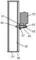
- the dust removing unit 45 includes a drive unit 54, a dust removing unit 55, a rail 61, and an elastic unit 56.
- the drive unit 54 has an electric motor 52 and a regulation unit 53.
- the restriction unit 53 converts the rotation of the electric motor 52 into reciprocating linear drive.
- the restricting portion 53 has an eccentric cam 62, a mover 63, a guide pin 64 and a guide hole 65.
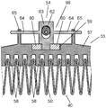
- the dust remover 55 has a bone portion 57, a claw portion 58, a groove portion 59 and a guide blade portion 60.
- the dust remover 55 is disposed such that its longitudinal direction is orthogonal to the ridge line direction of the filter 40.
- the elastic portion 56 transmits the reciprocating drive of the drive portion 54 to the dust remover 55 via the two compression springs (elastic bodies).
- a plurality of claws 58 disposed between valleys of the folds of the filter 40 are disposed below the square rod-like bones 57 disposed in the driving direction of the drive unit 54 (see FIG. 4B).
- the dust remover 55 has a groove 59 formed in the longitudinal direction at the upper center thereof, and has guide vanes 60 before and after the bone 57. Then, the guide vanes 60 are slidably fitted in the rails 61 disposed on both sides of the bone portion 57, whereby the dust remover 55 becomes movable along the rails 61.
- the rails 61 are supported by the inner lid 46 shown in FIG. 2, and both ends thereof also have a function of pressing and fixing the frame 51 of the filter 40 from above. Further, the support portion of the electric motor 52 is also supported by the inner lid 46 in the same manner as the rail 61.
- the restricting portion 53 has an eccentric cam 62 fixed at the axial center of the electric motor 52, and a mover 63 which is in contact with the eccentric cam 62 and converts rotation into reciprocating drive.
- the movable element 63 is a guide hole in which one end of the lower portion is slidably disposed in the groove 59 of the dust remover 55 and guide pins 64 disposed in the back and forth movable direction are formed at both ends of the groove 59 of the dust remover 55 It is slidably fitted in the reference numeral 65.
- the two compression springs which are elastic members of the elastic portion 56, are metal compression coil springs, which are disposed in the groove 59 and bias the mover 63 in a sandwiching manner.
- the elastic portion 56 expands and contracts when the mover 63 is driven in the groove 59, and the movement is transmitted to the dust remover 55 through the compression spring.
- the difference between the set length and the compression length of the compression spring, that is, the allowable deformation amount of the spring is desirably set larger than the reciprocating stroke of the mover 63. This is to prevent the electric motor 52 from locking and damage to the motor winding when the dust remover 55 does not move due to any failure.
- the filter 40 can be vibrated efficiently.
- a gap C is formed between the claw portion 58 of the dust remover 55 and the film body 50 of the filter 40.
- FIG. 5 is a view for explaining the gap C between the claw portion 58 of the dust remover 55 and the film body 50 of the filter 40 of the vacuum cleaner 49 according to the first embodiment of the present invention.
- the gap C corresponds to the center of the valley of the pleat of the filter 40 and the center of the claw 58
- the surface of the filter 40 and the claw 58 of the dust remover 55 It is a gap on one side of the tip.
- the clearance C is a condition for the dust remover 55 to move freely and the filter 40 not to prevent the dust remover 55 from resonating.
- about 80% (e.g., 0.8 mm) of 1/2 of the reciprocating stroke of the mover 63 is set as the gap C.
- the gap C not only improves the resonance condition of the dust remover 55, but also the inertial force of the dust remover 55 generated by the gap C acts on the film body 50 when the claw portion 58 contacts the film body 50. Therefore, since strong vibration is generated in the filter 40, the dust removal performance can be further enhanced.
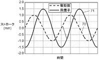
- FIG. 6 is a characteristic diagram showing the time change of the stroke of the drive unit 54 and the dust remover 55 of the vacuum cleaner 49 in the first embodiment of the present invention
- FIG. 7 is the dust remover of the same vacuum cleaner 49. It is a figure which shows the vibration characteristic of 55.
- the stroke 70 of the reciprocating drive of the mover 63 of the drive unit 54 has an amplitude (2 mm) twice the eccentricity amount (1 mm in this embodiment) of the electric motor 52 and the eccentric cam 62. It changes sinusoidally in). The cycle coincides with the rotation cycle of the electric motor 52.
- the stroke 71 of the operation of the dust remover 55 has the same cycle as the cycle of the stroke 70 of the mover 63 of the drive unit 54.
- the compression spring expands and contracts to drive the dust remover 55, so that the phase shifts accordingly.
- the resonance condition is satisfied, and as shown in FIG. 7, by driving at a frequency close to the resonance frequency 72, the amplitude of the stroke of the dust remover 55 is increased. Therefore, the operating frequency of the drive unit 54 is set to a resonance frequency region 73 in which the amplitude of the stroke 71 of the dust remover 55 is larger than the amplitude of the stroke 70 of the drive unit 54.
- the resonant frequency 72 is determined by the mass of the vibrating body and the stiffness of the spring supporting the vibrating body. As the mass increases, the resonant frequency 72 decreases, and as the stiffness of the spring increases, the resonant frequency 72 increases. Therefore, the resonant frequency 72 is determined by the weight of the dust remover 55 and the spring constant of the compression spring. However, the resonance frequency 72 changes due to factors affecting the resonance, such as the gap C between the filter 40 and the dust remover 55, the rigidity of the filter 40, the sliding resistance of the dust remover 55, and the like. For this reason, in setting the frequency, it is desirable to adjust by measurement.
- the amplitude of the reciprocating drive of the dust remover 55 is increased by the resonance action generated by the compression spring of the elastic portion 56 to vibrate the filter 40.
- the dust removing action of the dust remover 55 on the filter 40 is increased, and efficient dust removal is possible.
- the vacuum cleaner 49 which removes the dust adhering to the filter 40 in low noise and efficiently can be provided.
- the vacuum cleaner of this invention is not limited to the pleat filter which mentioned the kind of the filter 40 above.
- a flat filter can be used, and the same effect as in the case of using a pleated filter can be obtained as long as the vibration of the dust remover 55 is transmitted.
- a metal compression spring is used as an elastic body of the elastic portion 56
- a resin spring may be used, and a bellows or a piston or a cylinder filled with gas may be used. It is also possible to use air springs such as etc.
- the configuration of the restricting portion 53 an example has been shown in which the configuration in which the rotation of the electric motor 52 is converted into reciprocating drive by the mover 63 inscribed in the eccentric cam 62 is shown.
- the configuration of the regulation part of the vacuum cleaner of the present invention is not limited to this example.
- the rotation of the electric motor 52 may be converted into reciprocating drive by the crankshaft and the connecting rod, and the mover 63 may be moved.
- the elastic portion 56 includes, as an elastic body, a compression spring which can expand and contract in substantially the same direction as the driving direction of the driving portion 54, and the power of the driving portion 54 is obtained via the compression spring. It is transmitted to the dust remover 55.
- the spring load and the spring constant of the elastic portion 56 can be set arbitrarily. For this reason, since the resonant frequency 72 can also be set arbitrarily, the freedom degree of design of the drive part 54 or the dust remover 55 increases.
- the compression spring itself has little variation in spring constant and is unlikely to change with age, so it is highly reliable and has high stability.
- the amplitude of the dust remover 55 is stable with respect to the vibration frequency of the drive unit 54, and dust removal performance can be stably obtained at a high level.
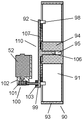
- FIG. 8 is a partial cross-sectional view showing the configuration of the filter 40 and the dust remover 96 in the vacuum cleaner according to the second embodiment of the present invention.
- the same parts as the parts described in the first embodiment are given the same reference numerals, and the description thereof is omitted.
- the structure of the whole vacuum cleaner in this Embodiment is the same as that of the structure of the vacuum cleaner 49 shown to FIG. 1 and FIG.
- the dust removing portion 96 of the present embodiment differs from the dust removing portion 45 of the first embodiment in that a rubber member disposed in a gap in the groove 59 as an elastic body of the elastic portion 80. Is the point used.
- the elastic body of the elastic portion 80 is a two rubber rectangular parallelepiped, and is disposed in the groove portion 59 so as to sandwich the mover 63.
- the rubber member expands and contracts, and the movement is transmitted to the dust remover 55 through the elastic portion 80.
- a polymer material such as a rubber member has both of a spring property and a damper property for damping vibration. Therefore, when the elastic body of the elastic portion 80 is made of rubber, the peak of the amplitude at the resonance frequency 72 becomes gentle as compared with the case where a compression spring is used as the elastic body as shown in FIG. Therefore, although the peak of the amplitude is reduced as compared with the case of using a spring, the resonant frequency region 73 is expanded, so that the frequency setting range is expanded and the design freedom is increased. In addition, since the rubber itself expands and contracts, it can be arranged in a narrow gap, and the degree of freedom in arrangement is increased.
- the mover 63 may be disposed at the center of a single elastic part 80.
- the elastic body of the elastic portion 80 is made of a flexible material such as rubber or elastomer from the viewpoint of easiness of manufacture and long life of the filter 40, and the space between the drive portion 54 and the dust collector 55 is flexible.
- the materials are provided.
- FIG. 9 is a cross-sectional view showing the configuration of the filter 40 and the dust removing unit 97 of the vacuum cleaner according to the third embodiment of the present invention
- FIG. 10 shows the configuration of the dust remover 85 of the vacuum cleaner. It is a perspective view.
- the same parts as the parts described in the first embodiment are assigned the same reference numerals and descriptions thereof will be omitted.
- the structure of the whole vacuum cleaner in this Embodiment is the same as that of the structure of the vacuum cleaner 49 shown to FIG. 1 and FIG.
- the dust removing unit 97 of this embodiment is different from the dust removing unit 45 of the first embodiment in the dust removing unit 85, the elastic unit 86, the mover 87, and the restriction
- a part of the part (the part excluding the eccentric cam 62) is a point integrally formed of the same material.
- the mover 87 is formed in a T-shape, and the eccentric cam 62 is inscribed in a gap in the center to convert the rotation of the eccentric cam 62 into a reciprocating drive. Both end portions of the T-shape are supported by two plate spring portions 88.
- the plate spring portion 88 is supported at its lower end by the bone portion 57 and disposed in the vertical direction.
- the plate spring portion 88 supports the mover 87 at its upper end, and is arranged such that the mover 87 can move in the same direction as the dust collector 85 operates.
- the plate spring portion 88 is integrally formed with the dust remover 85, and reduces the stress on the plate spring portion 88 at the time of movement by reducing the thickness (for example, a thickness of 0.3 mm). The presence of the plate spring portion 88 makes it possible to suppress the movement of the dust remover 85 in the vertical direction.
- the mechanism (except for the eccentric cam 62) of the restricting portion for converting the rotation of the eccentric cam 62 into the reciprocating drive is also integrally formed of the same material as the dust remover 85.
- the elastic portion 86 is configured in a meandering manner.
- the elastic portions 86 are springy when displaced, and are disposed at two positions on both sides of the movable element 87 in the moving direction.
- One end of the elastic portion 86 is connected to the mover 87, and the other end is connected to the upper portion of the bone portion 57.
- the elastic portion 86 expands and contracts, and the movement is transmitted to the bone portion 57 via the elastic portion 86.
- the dust remover 85 by integrally forming the dust remover 85, the elastic portion 86, and the mover 87, the number of parts can be reduced, and the manufacturing cost can be reduced (parts cost reduction, assembly work reduction). Can reduce the occurrence of defective products).
- the parts are integrally formed, there is no wear or noise between the parts, and the positional accuracy can be improved.
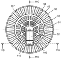
- FIG. 11 is a perspective view showing the configuration of the filter 90 and the dust removing unit 110 of the vacuum cleaner according to the fourth embodiment of the present invention
- FIG. 12A is a view of the filter 90 and the dust removing unit 110 of the vacuum cleaner
- 12B is a cross-sectional view showing the configuration of the filter 90 and the dust removing unit 110 of the vacuum cleaner
- FIG. 12C shows the configuration of the filter 90 and the dust removing unit 110 of the vacuum cleaner. It is a sectional view showing.
- the same parts as the parts described in the first embodiment are given the same reference numerals, and the description thereof is omitted.
- the structure of the whole vacuum cleaner in this Embodiment is the same as that of the structure of the vacuum cleaner 49 shown to FIG. 1 and FIG.
- the difference from the first embodiment is that the film body 91 of the filter 90 is not a parallel fold but an end of the fold is spread like a disk. And the point where the dust remover 92 is configured in a circular shape in accordance with the configuration of the fold of the membrane body 91. The details will be described below.
- one end of a fold is spread in a disk shape, and the membrane body 91 in which ridge lines of the fold are radially configured is integrally made of resin so as to be sandwiched between the cylindrical outer frame 93 and the inner frame 94. It is molded. At the center of the inner frame 94, a bearing hole 95 is provided.
- a shaft portion 106 fitted in the bearing hole 95 is disposed at the center, and a circular bone portion 107 centering on the shaft portion 106 is configured. Then, below the circular bone portion 107, a plurality of claw portions 98 disposed in the valleys of the respective folds of the filter 90 are radially arranged. That is, the claw portion 98 is configured to be rotatable in an arc shape around the shaft portion 106. Moreover, the groove part 99 is provided in the tangent direction of the circle
- the restricting portion 100 includes an eccentric cam 62 fixed at the axial center of the electric motor 52, and a mover 101 which is in contact with the eccentric cam 62 and converts rotation into reciprocating drive.
- the mover 101 is configured such that one end of the lower portion is disposed in the groove 99 of the dust remover 92 so that the drive direction of the mover 101 coincides with the tangential direction of the circle of the bone 107.
- the mover 101 is slidably supported by the guide 102 in the horizontal direction in the drive direction.
- the mover 101 is restricted so that the reciprocating drive becomes linear.
- the guide 102 also supports the electric motor 52 and is supported by the inner lid 46 shown in FIG.
- the elastic portion 103 includes, as an elastic body, a rectangular parallelepiped made of rubber.
- the elastic portion 103 is disposed in the groove 99 and has a hole at the upper center. One end of the lower part of the mover 101 is inserted into this hole. Accordingly, when the mover 101 is driven in the groove 99, the elastic portion 103 expands and contracts, and the movement is transmitted to the dust remover 92.
- a clearance C is formed between the claw portion 98 of the dust remover 92 and the film body 91 of the filter 90.
- the clearance C is an important condition for the dust remover 92 to move freely and the filter 90 not to interfere with the resonance of the dust remover 92.
- about 80% (e.g., 0.8 mm) of 1/2 of the reciprocating stroke of the mover 101 is set as the gap C.
- This gap C is 20% to 150% (10% to 75% of the reciprocating stroke of the movable element 101) to 1/2 of the reciprocating stroke of the movable element 101 (amount of eccentricity between the electric motor 52 and the eccentric cam 62).
- the dust remover 92 resonates, and the dust removal effect of the filter 90 can be enhanced.
- the gap C not only improves the resonance condition of the dust remover 92, but when the claw portion 98 contacts the film body 91, the inertial force of the dust remover 92 generated by the gap C acts on the film body 91. Therefore, since strong vibration is generated in the filter 90, the dust removal performance can be further enhanced.
- the reciprocation vibration of the mover 101 is removed through the elastic portion 103.
- What can be transmitted to 92 is similar to the other embodiments. Therefore, the resonance condition is satisfied in the dust remover 92. Therefore, the amplitude of the dust remover 92 can be increased by the resonance action, and the dust removal effect on the filter 90 can be improved.
- the drive of the drive unit is transmitted to the dust remover through the elastic unit.
- the resonance condition mainly consists of the spring constant of the elastic portion and the weight of the dust remover, and the amplitude of the dust remover can be increased by bringing the frequency of the drive portion closer to this resonance frequency. Therefore, the filter provided in the vicinity of the dust collector vibrates largely, and dust can be efficiently removed.
- the reciprocating drive of the drive unit is transmitted to the dust collector via the elastic body, no collision noise is generated between the drive unit and the dust collector. Therefore, the vacuum cleaner which removes the dust adhering to the filter with low noise and with high efficiency can be provided.
- the clearance C is provided between the dust collector and the filter, and the clearance C is set to a predetermined range with respect to 1/2 of the reciprocating drive amplitude of the drive unit.
- the filter damps the resonant operation of the dust remover, and by providing the gap C, the effect of the dust remover on the resonant operation can be reduced.
- the drive unit includes a motor that is electrically rotated, and a regulation unit that converts the rotation of the motor to reciprocating linear drive. It is preferable to make the allowable deformation amount of the elastic portion caused by the drive deviation between the portion and the dust collector larger than the reciprocation driving amount of the regulating portion.
- the allowable deformation amount of the elastic portion is larger than the reciprocation driving amount of the conversion portion, so that the motor can rotate without locking even if the dust remover does not move, for example. It can prevent.
- dust attached to the filter can be removed with low noise and with high efficiency by using the resonance action. Therefore, a vacuum cleaner or the like provided with a filter for filtering dust Useful as.
Landscapes
- Engineering & Computer Science (AREA)
- Mechanical Engineering (AREA)
- Chemical & Material Sciences (AREA)
- Chemical Kinetics & Catalysis (AREA)
- Filters For Electric Vacuum Cleaners (AREA)
Abstract
電気掃除機であって、電動送風機と、電動送風機によって吸引される塵埃を補足するフィルタ(40)と、フィルタ(40)に付着した塵埃を除去する除塵部(45)とを備えている。除塵部(45)は、直線駆動するための規制部(53)を有し、往復駆動する駆動部(54)と、フィルタ(40)に近接して配置され、駆動部(54)の往復駆動の方向と、実質的に同方向に可動する除塵子(55)と、駆動部(54)の往復駆動を、弾性体を介して前記除塵子に伝達する弾性部(56)とを有している。除塵子(55)の往復駆動の振幅を、弾性部(56)によって生じる共振作用により増大させて、フィルタ(40)を振動させる。
Description
本発明は、塵埃を濾過するフィルタを備えた電気掃除機に関する。
従来から、電気掃除機の分野における、フィルタの目詰まりを防止する手段として、フィルタに振動を与えて除塵する方法が提案されている。例えば、断面が波形状に折り曲げられ、複数のひだが形成されたフィルタにおいて、それぞれのひだに嵌め込まれた複数の爪部を振動させる除塵部を備えた掃除機が提案されている(例えば、特許文献1参照)。
図13は、従来の電気掃除機1000の概略構成を示す模式図である。図14は、従来の電気掃除機1000における、フィルタ装置1111の構成を示す斜視図である。
図13および図14に示すように、電気掃除機1000は、電動送風機1110によって吸引される塵埃を補足するフィルタ装置1111と、フィルタ装置1111を振動させるバイブレータ1112とを備えている。電動送風機1110の駆動前または駆動後に、バイブレータ1112によってフィルタ装置1111を振動させて、フィルタ装置1111に捕捉された塵埃を除去する。
フィルタ装置1111は、矩形の枠フレーム1113と、シート体1116と、振動伝達部材1117とを有している。シート体1116は、枠フレーム1113に内設され、波状に折り曲げられることにより、複数の凸部1114および凹部1115が形成されている。振動伝達部材1117は、シート体1116にバイブレータ1112の振動を伝達する。
バイブレータ1112は、内部に振動モータを有し、フィルタ装置1111に並設されている。
振動伝達部材1117は、シート体1116の複数の凹部1115それぞれに嵌め込まれた複数の爪部1118と、バイブレータ1112からの振動を直接受けとる伝達突部1119とを備えている。
バイブレータ1112の振動は、伝達突部1119から振動伝達部材1117に伝わり、この振動は爪部1118からシート体1116に伝わる。これにより、シート体1116に捕捉された塵埃を除去できる。
しかしながら、このような従来の電気掃除機1000においては、除塵性能の高効率化と低騒音化の観点において、改善の余地がある。
すなわち、前述したように、従来の電気掃除機1000においては、バイブレータ1112は、フィルタ装置1111と並設して配置されている。このため、バイブレータ1112の振動は、伝達突部1119を振動させると同時に、フィルタ装置1111全体を振動させてしまう。したがって、バイブレータ1112の振動エネルギーは、フィルタ装置1111だけでなく、ひいてはフィルタ装置1111を支える電気掃除機1000全体に拡散してしまう。
また、前述したように、バイブレータ1112からの振動は、振動伝達部材1117の伝達突部1119に伝わり、爪部1118を振動させて、シート体1116に伝わる。このため、バイブレータ1112の振動がシート体1116に伝わるまでの伝達ロスが大きく、振動が減衰してしまう。
そのため、シート体1116を振動させて充分な除塵性能を得るためには、振動発生源の出力を上げる必要があり、バイブレータ1112の大型化が避けられない。
さらに、バイブレータ1112の振動を、振動伝達部材1117の伝達突部1119が直接受けるため、衝突音が発生して騒音が発生する。
本発明は、フィルタに付着した塵埃を低騒音でかつ高効率に除去する電気掃除機を提供するものである。
本発明の電気掃除機は、電動送風機と、電動送風機によって吸引される塵埃を補足するフィルタと、フィルタに付着した塵埃を除去する除塵部とを備えている。除塵部は、直線駆動するための規制部を有し、往復駆動する駆動部と、フィルタに近接して配置され、駆動部の往復駆動の方向と、実質的に同方向に可動する除塵子と、駆動部の往復駆動を、弾性体を介して除塵子に伝達する弾性部とを有している。除塵子の往復駆動の振幅を、弾性部によって生じる共振作用により増大させてフィルタを振動させる。
以下、図面を参照しながら、本発明の実施の形態について詳細に説明する。なお、以下の説明では、同一の部分、または、相当する部分には、同一の符号を付して、重複する説明を省略する場合がある。
(第1の実施の形態)
図1は、本発明の第1の実施の形態における、電気掃除機49の外観を示す側面図である。図2は、同電気掃除機49の本体要部の構成を示す断面図である。図3は、同電気掃除機49のフィルタ40および除塵部45の構成を示す斜視図である。図4Aは、同電気掃除機49のフィルタ40および除塵部45の構成を示す平面図である。図4Bは、同電気掃除機49のフィルタ40および除塵部45の構成を示す断面図である。図4Cは、同電気掃除機49のフィルタ40および除塵部45の構成を示す断面図である。
図1は、本発明の第1の実施の形態における、電気掃除機49の外観を示す側面図である。図2は、同電気掃除機49の本体要部の構成を示す断面図である。図3は、同電気掃除機49のフィルタ40および除塵部45の構成を示す斜視図である。図4Aは、同電気掃除機49のフィルタ40および除塵部45の構成を示す平面図である。図4Bは、同電気掃除機49のフィルタ40および除塵部45の構成を示す断面図である。図4Cは、同電気掃除機49のフィルタ40および除塵部45の構成を示す断面図である。
図1に示すように、電気掃除機49の掃除機本体1の外部には、車輪3およびキャスター4が取り付けられており、掃除機本体1は床面を自在に移動できる。集塵ケース5設置部分の下方に設けられた吸引口6には、吸引ホース7、および延長管8が順次接続されており、延長管8の先端には、吸込具9が取り付けられている。
図2に示すように、掃除機本体1内には、電動送風機21が内蔵されている。電動送風機21の上流側には、通気口22を有する隔壁26を介して、集塵ケース5が、掃除機本体1に対して着脱自在に配置されている。電動送風機21を運転することにより、掃除機本体1内に、家屋の床面上の塵埃を吸引することができる。集塵ケース5は、吸引した塵埃を含む空気を導入し、塵埃を遠心分離して堆積し、かつ微細な塵埃を濾過する。濾過された空気は、電動送風機21下流の排気出口(図示せず)から排気される(サイクロン型掃除機)。
集塵ケース5は、吸気口30を有し、下部側に配置される中空円筒形状の集塵ボックス31と、排気口32を有し、上部側に配置される集塵蓋33とを備えている。集塵ケース5は、掃除機本体1に装着された状態において、吸気口30と掃除機本体1の吸引口6とが連通し、排気口32と掃除機本体1の通気口22とが連通するように構成されている。
集塵ボックス31は、その内部に、径の異なる中空円筒および中空円錐を多段に重ねた形状の中ケース34を有している。中ケース34は、上から順に、フィルタ収容ケース35、傾斜筒A36、一次フィルタ37、傾斜筒B38、および細塵筒39が連続して接続されて、構成されている。
フィルタ収容ケース35は、中空円筒状であり、内部にフィルタ40を納め、外周が集塵ボックス31内面の上端部に沿うように収められている。フィルタ収容ケース35の外面と集塵ボックス31の内面とは、シール部材(図示せず)で隙間を塞ぐように構成されている。
傾斜筒A36は、中空円錐状であり、フィルタ40に捕捉された塵埃を除去する際、フィルタ40から落下する塵埃を、一次フィルタ37、傾斜筒B38および細塵筒39へと導くための斜面を内部に有している。
一次フィルタ37は、全面に微小な貫通孔を有する円筒形状であり、円筒外周から円筒内部へ空気を通過させることにより、吸引気流中の塵埃から綿埃、毛髪等の、比較的サイズの大きい塵埃(粗塵)を濾し取る。
傾斜筒B38は、傾斜筒A36と同様に中空円錐状であり、フィルタ40から落下する塵埃を、細塵筒39へと導くための斜面を内部に有している。
そして、細塵筒39は、中空円筒形状であり、傾斜筒B38から導かれた塵埃を内部に溜め置くものである。集塵ボックス31の底内面には、細塵筒39の底面との間をシールするパッキン41が設けられている。
吸気口30は、吸引気流が集塵ボックス31内面の接線方向に流れるように開口している。吸引気流は、傾斜筒A36、一次フィルタ37、傾斜筒B38および細塵筒39それぞれの外面と、集塵ボックス31内面との隙間で構成される流路を旋廻する。吸引気流は、最終的には、一次フィルタ37で円筒内部に吸引されて、フィルタ40方向へと流れる。
吸気口30から集塵ボックス31に流入する吸引気流中の塵埃は、遠心力によって集塵ボックス31の内面に押付けられるように旋廻しながら、集塵ボックス31の下部へと移動して、集塵ボックス31の底部に集積される。一次フィルタ37の下部には、集積された塵埃が舞い上がらないように、庇部42が設けられている。すなわち、この庇部42よりも下部が塵埃の集積部であり、庇部42よりも上部が遠心分離部となる。
集塵ボックス31の底部には、開閉自在の底蓋43が装着されている。集塵ボックス31に溜まった塵埃を廃棄する場合、この底蓋43を開放することにより、簡単に塵埃を捨てることができる。また、細塵筒39も底部が開放されるので、細塵筒39の中に溜まった塵埃も同時に廃棄することができる。
遠心分離されにくい、粒子径の細かい砂塵、花粉、またはダニ糞等の塵埃(細塵)の大半は、気流とともに一次フィルタ37を通過してフィルタ40へ流れる。このような塵埃(細塵)は、フィルタ40で濾し取られてフィルタ40の表面に付着して堆積するとともに、一部は、集塵ボックス31底部に堆積された粗塵に絡んで貯留する。
集塵蓋33は円筒形状であり、集塵ボックス31の上部に、気密を保った状態で装着されている。集塵蓋33は、その内部に、振動によってフィルタ40に付着した塵埃を除去する除塵部45を収容している。また、電装部品は内蓋46内に収められている。
電装部品は、プリント基板、給電端子、充電部品、モータドライバ素子、および、オンオフスイッチ等を含む。掃除機本体1から、給電端子を経て、充電部品に電気が蓄えられる。除塵部45は、充電部品からの電力により駆動される。除塵部45の駆動制御は、掃除機本体1内のマイコン(図示せず)からの指示、および、集塵蓋33のオンオフスイッチ(図示せず)からの指示の何れか一方により駆動する。
このように、除塵部45は、充電部品の働きにより、電源コンセント(図示せず)を抜いた状態や、集塵ケース5を掃除機本体1から外した状態でも動作する。
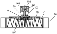
次に、図3、図4A、図4Bおよび図4Cに基づいて、フィルタ40および除塵部45の構成について詳細に説明する。
円盤状のフィルタ40の下流側(上部)に、フィルタ40と平行に、除塵部45が配置されている。
フィルタ40としては、不織布、パルプ、ガラス繊維、または、HEPA(High Efficiency Particulate Air)フィルタ等を用いることができる。本実施の形態では、塵離れ性に優れた、PTFE(PolyTetraFluoroEthylene)膜を不織布に積層した濾膜を、波状にひだを構成するように折って形成した膜体50を、円筒状の枠体51の内側に樹脂で一体成型している。
除塵部45は、駆動部54、除塵子55、レール61および弾性部56を有している。駆動部54は、電動モータ52および規制部53を有している。規制部53は、電動モータ52の回転を往復直線駆動に変換する。規制部53は、偏芯カム62、可動子63、ガイドピン64およびガイド穴65を有している。除塵子55は、骨部57、爪部58、溝部59およびガイド羽根部60を有している。
除塵子55は、その長手方向が、フィルタ40の、ひだの稜線方向と直交するように配置されている。弾性部56は、駆動部54の往復駆動を2本の圧縮バネ(弾性体)を介して除塵子55に伝達する。
駆動部54の駆動方向に向けて配置した角棒状の骨部57の下方には、フィルタ40の各ひだの谷間に配置する複数の爪部58が配置されている(図4B参照)。除塵子55は、その上部中央に、長手方向に構成された溝部59を有し、骨部57の前後にはガイド羽根部60を有している。そして、骨部57の両側に配置したレール61に、ガイド羽根部60を摺動自在に嵌め込むことによって、レール61に沿って、除塵子55が可動自在となる。
レール61は、図2に示した内蓋46に支持されており、その両端がフィルタ40の枠体51を上から押さえて固定する役目も有している。また、電動モータ52の支持部も、レール61と同様に、内蓋46によって支持されている。
規制部53は、電動モータ52の軸心に固設した偏芯カム62と、偏芯カム62に内接して回転を往復駆動に変換する可動子63とを有している。可動子63は、下部の一端を除塵子55の溝部59内に摺動自在に配置して、前後可動方向に配置されたガイドピン64を、除塵子55の溝部59両端部に構成したガイド穴65に摺動自在に嵌め込んだものである。
弾性部56の弾性体である二本の圧縮バネは、金属製の圧縮コイルバネであり、溝部59内に設置され、可動子63を挟むように付勢している。弾性部56は、可動子63が溝部59内で駆動される際に伸縮し、圧縮バネを介して除塵子55に動きが伝達される。
圧縮バネのセット長と圧縮長との差、すなわちバネの許容変形量は、可動子63の往復ストロークよりも大きく設定することが望ましい。これは、除塵子55が何らかの障害で動かなくなった場合に、電動モータ52がロックしてモータ巻線が損傷することを防止するためである。
以上の構成において、電動モータ52を運転すると、偏芯カム62が回転する。これにより、電動モータ52と偏芯カム62との偏芯量(例えば1mm)の倍のストローク(例えば2mm)で、可動子63が溝部59に沿って往復駆動される。この可動子63の動作に伴い、圧縮バネが伸縮して、除塵子55に対する二本の圧縮バネの付勢力に差が生じ、除塵子55がレール61に沿って駆動される。そして、除塵子55の爪部58が、フィルタ40のひだの側面に接触して、ひだを振動させる。
この時、除塵子55と可動子63とは同一の直線方向に移動し、圧縮バネも同一方向に伸縮するので、駆動の方向が一致し、伝達ロスが少ない。また、爪部58の駆動方向が、フィルタ40のひだに直交するように配置されているので、フィルタ40を効率よく振動させることができる。
除塵子55の爪部58と、フィルタ40の膜体50との間には、隙間Cが形成されている。
図5は、本発明の第1の実施の形態における電気掃除機49の、除塵子55の爪部58と、フィルタ40の膜体50との隙間Cについて説明するための図である。図5に示したように、隙間Cは、フィルタ40のプリーツの谷部の中心と、爪部58の中心とを一致させた場合に、フィルタ40表面と除塵子55の爪部58との、先端における片側の隙間のことである。この隙間Cは、除塵子55が自由に可動して、フィルタ40が除塵子55の共振を妨げないための条件となる。本実施の形態では、可動子63の往復ストロークの1/2の約80%(例えば0.8mm)を隙間Cとして設定している。この隙間Cを、可動子63の往復ストロークの1/2(電動モータ52と偏芯カム62との偏芯量)の20%~150%(可動子63の往復ストロークの10%~75%)とすることにより、除塵子55が共振して、フィルタ40の除塵効果を高めることができる。なお、さらに効果を上げるには、可動子63の往復ストロークの1/2(電動モータ52と偏芯カム62との偏芯量)の50%~120%(可動子63の往復ストロークの25%~60%)とするとすることが望ましい。
この隙間Cは、除塵子55の共振条件を良くするだけでなく、爪部58が膜体50に接触する際に、この隙間Cによって生じる除塵子55の慣性力が膜体50に作用する。よって、フィルタ40に強い振動を発生させるので、除塵性能をより高めることができる。
次に、図6および図7を用いて、除塵動作について説明する。図6は、本発明の第1の実施の形態における電気掃除機49の駆動部54および除塵子55のストロークの時間変化を示す特性図であり、図7は、同電気掃除機49の除塵子55の振動特性を示す図である。
図6に示すように、駆動部54の可動子63の往復駆動のストローク70は、電動モータ52と偏芯カム62との偏芯量(本実施の形態では1mm)の2倍の振幅(2mm)で正弦波状に変化する。周期は電動モータ52の回転周期と一致する。
除塵子55の動作のストローク71は、その周期が、駆動部54の可動子63のストローク70の周期と同一である。しかしながら、圧縮バネが伸縮して除塵子55が駆動されるため、その分、位相がずれる。振幅は、圧縮バネを有することにより、共振条件が成り立ち、図7に示すように、共振周波数72に近い周波数で駆動させることによって除塵子55のストロークの振幅が増大する。よって、駆動部54の運転周波数を、除塵子55のストローク71の振幅が、駆動部54のストローク70の振幅よりも増大する共振周波数領域73に設定する。
一般的に、共振周波数72は、振動体の質量と、振動体を支えているバネの剛性で決まる。質量が大きくなると、共振周波数72は低下し、バネの剛性が大きくなると、共振周波数72は上昇する。したがって、除塵子55の重量と、圧縮バネのバネ定数によって共振周波数72が決まる。ただし、フィルタ40と除塵子55との隙間Cや、フィルタ40の剛性、除塵子55の摺動抵抗等の、共振への影響因子により共振周波数72が変化する。このため、周波数の設定にあたっては、実測による調整をすることが望ましい。
以上のように、本実施の形態においては、除塵子55の往復駆動の振幅を、弾性部56の圧縮バネによって生じる共振作用によって増大させて、フィルタ40を振動させるようにした。これにより、除塵子55のフィルタ40への除塵作用が増大し、効率のよい除塵が可能となる。
また、本実施の形態においては、駆動部54の往復駆動を、弾性部56を介して除塵子55に伝達するので、駆動部54と除塵子55との間で衝突音が発生することがない。よって、フィルタ40に付着した塵埃を低騒音でかつ高効率に除去する電気掃除機49を提供することができる。
以上、本実施の形態における電気掃除機49のフィルタ40の構成および作用について説明したが、本発明の電気掃除機は、そのフィルタ40の種類を、上述したプリーツフィルタに限定されるものではない。例えば、平板状のフィルタを用いることもでき、除塵子55の振動が伝わりさえすれば、プリーツフィルタを用いた場合と同様の効果を得ることができる。
また、本実施の形態においては、駆動部54の構成として、電動モータ52と偏芯カム62を用いた例を示したが、リニアモータ等の直線往復駆動が可能な手段を用いることも可能である。
さらに、本実施の形態においては、弾性部56の弾性体として、金属の圧縮バネを用いた例を示したが、樹脂製のバネを用いることもできるし、ガスを封入したベローズやピストン・シリンダ等のような空気バネを用いることも可能である。
また、本実施形態においては、規制部53の構成として、電動モータ52の回転を、偏芯カム62に内接する可動子63により往復駆動に変換する構成を用いた例を示した。しかしながら、本発明の電気掃除機の規制部の構成はこの例に限定されない。例えば、電動モータ52の回転を、クランクシャフトとコネクティングロッドとにより往復駆動に変換して、可動子63を動かすようにしてもよい。
また、本実施の形態においては、弾性部56が、駆動部54の駆動方向と実質的に同じ方向に伸縮する圧縮バネを弾性体として有し、駆動部54の動力を、圧縮バネを介して除塵子55に伝達している。
この構成により、弾性部56のバネ荷重やバネ定数を任意に設定できる。このため、共振周波数72も任意に設定することができるので、駆動部54や除塵子55の設計の自由度が増す。
さらに、例えばフィルタ40の、ひだ自体の共振周波数と除塵子55の周波数とを近接させて、より効率的な除塵が可能になる。
また圧縮バネ自体は、バネ定数のばらつきが少なく、経年変化もしにくいので信頼性が高く安定性も高まる。このように、除塵子55の周波数が安定するので、駆動部54の振動周波数に対して除塵子55の振幅が安定し、除塵性能を高いレベルで安定に得ることができる。
(第2の実施の形態)
次に、本発明の第2の実施の形態に係る電気掃除機における、除塵部96の構成について、図面を用いて詳細に説明する。図8は、本発明の第2の実施の形態に係る電気掃除機におけるフィルタ40および除塵部96の構成を示す部分断面図である。なお、第1の実施の形態で説明した部分と同一の部分については、同一の符号を付与してその説明を省略する。また、本実施の形態における、電気掃除機全体の構成は、図1および図2に示した電気掃除機49の構成と同様である。
次に、本発明の第2の実施の形態に係る電気掃除機における、除塵部96の構成について、図面を用いて詳細に説明する。図8は、本発明の第2の実施の形態に係る電気掃除機におけるフィルタ40および除塵部96の構成を示す部分断面図である。なお、第1の実施の形態で説明した部分と同一の部分については、同一の符号を付与してその説明を省略する。また、本実施の形態における、電気掃除機全体の構成は、図1および図2に示した電気掃除機49の構成と同様である。
図8に示すように、本実施の形態の除塵部96が、第1の実施の形態の除塵部45と異なるのは、弾性部80の弾性体として、溝部59内の隙間に配置したゴム部材を用いた点である。弾性部80の弾性体は、二個のゴム製直方体であり、溝部59内に、可動子63を挟むように配置されている。これにより、可動子63が溝部59内で駆動される際に、ゴム部材が伸縮し、弾性部80を介して除塵子55に動きが伝達される。
ゴム部材等の高分子材料は、バネ性と、振動を減衰するダンパ性との両性質を兼ね備えている。よって、弾性部80の弾性体をゴム製にすることにより、図7に示したような、弾性体として圧縮バネを用いた場合と比較して、共振周波数72における振幅のピークが緩やかになる。したがって、バネを用いた場合と比べて、振幅のピークは減少するが、共振周波数領域73は拡大するので、周波数設定可能範囲が広がり、設計の自由度が増す。また、ゴムは材料自体が伸縮するので、狭い隙間にも配置でき、配置の自由度が増す。
なお、本実施の形態では、弾性部80の弾性体の材質として、ゴムを用いた例を示したが、エラストマや発泡樹脂等の柔軟材料を用いることも可能である。また、本実施の形態においては、二つの弾性部80を用いた例を示したが、単一の弾性部80の中央に、可動子63を配置する構成としてもよい。
本実施の形態においては、作りやすさとフィルタ40の長寿命の観点から、弾性部80の弾性体を、ゴム、エラストマ等の柔軟材料により構成し、駆動部54と除塵子55との隙間に柔軟材料を配設している。
(第3の実施の形態)
次に、本発明の第3の実施の形態に係る電気掃除機における除塵部97の構成について、図面を用いて詳細に説明する。図9は、本発明の第3の実施の形態に係る電気掃除機のフィルタ40および除塵部97の構成を示す断面図であり、図10は、同電気掃除機の除塵子85の構成を示す斜視図である。なお、第1の実施の形態で説明した部分と同一の部分については、同一の符号を付与して、説明を省略する。また、本実施の形態における、電気掃除機全体の構成は、図1および図2に示した電気掃除機49の構成と同様である。
次に、本発明の第3の実施の形態に係る電気掃除機における除塵部97の構成について、図面を用いて詳細に説明する。図9は、本発明の第3の実施の形態に係る電気掃除機のフィルタ40および除塵部97の構成を示す断面図であり、図10は、同電気掃除機の除塵子85の構成を示す斜視図である。なお、第1の実施の形態で説明した部分と同一の部分については、同一の符号を付与して、説明を省略する。また、本実施の形態における、電気掃除機全体の構成は、図1および図2に示した電気掃除機49の構成と同様である。
図9および図10に示すように、本実施の形態の除塵部97が、第1の実施の形態の除塵部45の構成と異なるのは、除塵子85、弾性部86、可動子87と規制部の一部(偏芯カム62を除く部分)が、同一材料で一体に構成されている点である。
可動子87は、T字形に構成され、中心部の空隙に偏芯カム62を内接して、偏芯カム62の回転を往復駆動に変換している。T字形の両端部分は、二枚の板バネ部88によって支えられている。この板バネ部88は、下端を骨部57によって支持され、垂直方向に配置されている。板バネ部88は、上端で可動子87を支持し、可動子87が除塵子85の動作方向と同じ方向に可動となるように配置されている。板バネ部88は、除塵子85と一体に構成され、肉厚を薄く(例えば肉厚0.3mm)することによって、可動時の板バネ部88への応力を低減させている。板バネ部88が存在することによって、除塵子85の垂直方向の動きを抑制することが可能となる。
このように、偏芯カム62の回転を往復駆動に変換するための規制部の機構(偏芯カム62を除く)も、除塵子85と同一材料で一体に構成されている。
弾性部86は、蛇行状に構成されている。弾性部86は、変位させることによってバネ性を生じ、可動子87の可動方向の両側の二箇所に配置されている。弾性部86の一端を可動子87に接続し、他端を骨部57の上部に接続する。これにより、可動子87が往復駆動する際に弾性部86が伸縮し、弾性部86を介して骨部57に動きが伝達される。
以上述べたように、本実施の形態によれば、除塵子85、弾性部86および可動子87を一体に構成することにより、部品点数が減らせ、製造コスト削減(部品コスト削減、組み立て作業の削減による不良品の発生低減等)が可能となる。また、部品を一体に構成しているので、部品間の磨耗や騒音がなく、位置精度を向上させることができる。
(第4の実施の形態)
次に、本発明の第4の実施の形態に係る電気掃除機に用いるフィルタ90および除塵部110について、図面を用いて詳細に説明する。
次に、本発明の第4の実施の形態に係る電気掃除機に用いるフィルタ90および除塵部110について、図面を用いて詳細に説明する。
図11は、本発明の第4の実施の形態に係る電気掃除機のフィルタ90および除塵部110の構成を示す斜視図であり、図12Aは、同電気掃除機のフィルタ90および除塵部110の構成を示す正面図であり、図12Bは、同電気掃除機のフィルタ90および除塵部110の構成を示す断面図であり、図12Cは、同電気掃除機のフィルタ90および除塵部110の構成を示す断面図である。なお、第1の実施の形態で説明した部分と同一の部分については、同一の符号を付与してその説明を省略する。また、本実施の形態における、電気掃除機全体の構成は、図1および図2に示した電気掃除機49の構成と同様である。
図11、図12A~図12Cに示すように、第1の実施の形態と異なるのは、フィルタ90の膜体91を、平行のひだ折ではなく、ひだ折の一端を円盤状に広げて構成した点、および、除塵子92を、膜体91のひだの構成に合わせて、円状に構成した点にある。以下、その詳細を説明する。
フィルタ90は、ひだ折の一端を円盤状に広げ、ひだの稜線を放射状に構成した膜体91を、円筒状の外枠体93と内枠体94との間に挟み込むように樹脂で一体に成型したものである。内枠体94の中心には、軸受穴95が設けられている。
除塵子92は、中心に軸受穴95に嵌合させた軸部106を配置し、この軸部106を中心とした円状の骨部107を構成している。そして、その円状の骨部107の下方に、フィルタ90の、各ひだの谷間に配置する複数の爪部98を放射状に配置している。つまり、軸部106を中心として、爪部98が円弧状に回動自在に構成されている。また、骨部107上方の一箇所の、骨部107の円の接線方向に、溝部99を備えている(図11を参照)。
規制部100は、電動モータ52の軸心に固設した偏芯カム62と、この偏芯カム62に内接して、回転を往復駆動に変換する可動子101とを備えている。可動子101は、下部の一端を除塵子92の溝部99内に配置して、可動子101の駆動方向と骨部107の円の接線方向とが一致するように構成されている。
可動子101は、ガイド102により、駆動方向を水平左右方向に摺動支持されている。可動子101は、往復駆動が直線状となるような規制を受けている。このガイド102は、電動モータ52も支持し、かつ、図2に示した内蓋46に支持されている。
弾性部103は、弾性体として、ゴム製の直方体を含む。弾性部103は溝部99内に配置され、中央上方に穴を有している。可動子101の下部の一端が、この穴に挿入されている。これにより、可動子101が溝部99内で駆動する際に、弾性部103が伸縮して、除塵子92に動きが伝達される。
なお、除塵子92の、爪部98とフィルタ90の膜体91との間には、隙間Cが形成されている。この隙間Cは、除塵子92が自由に可動して、フィルタ90が除塵子92の共振を妨げないための重要な条件となる。本実施の形態では、可動子101の往復ストロークの1/2の約80%(例えば0.8mm)を隙間Cとして設定している。この隙間Cを、可動子101の往復ストロークの1/2(電動モータ52と偏芯カム62との偏芯量)の20%~150%(可動子101の往復ストロークの10%~75%)とすることにより、除塵子92が共振して、フィルタ90の除塵効果を高めることができる。なお、さらに効果を上げるには、可動子101の往復ストロークの1/2(電動モータ52と偏芯カム62との偏芯量)の50%~120%(可動子101の往復ストロークの25%~60%)とするとすることが望ましい。
この隙間Cは、除塵子92の共振条件を良くするだけでなく、爪部98が膜体91に接触する際に、この隙間Cによって生じる除塵子92の慣性力が膜体91に作用する。よって、フィルタ90に強い振動を発生させるので、除塵性能をより高めることができる。
また、本実施の形態においても、電動モータ52による往復駆動を、弾性部103を介して除塵子92に伝達するので、可動子101と除塵子55との間で衝突音が発生することがない。よって、フィルタ90に付着した塵埃を低騒音でかつ高効率に除去する電気掃除機を提供することができる。
以上述べたように、フィルタ90のひだの稜線方向が放射状であって、除塵子92の往復振動方向が円弧状であっても、可動子101の往復振動を、弾性部103を介して除塵子92に伝達できることは、他の実施の形態と同様である。したがって、除塵子92に共振条件が成り立つことになる。したがって、共振作用により、除塵子92の振幅が増大して、フィルタ90への除塵効果を向上させることができる。
なお、本実施の形態では、弾性部103の材質としてゴムを用いた例を示したが、金属のバネやエラストマ・発泡樹脂等の柔軟材料を用いることも可能である。
以上述べたように、各実施の形態の電気掃除機においては、駆動部の駆動を弾性部を介して除塵子に伝達する構成としている。これにより、主に弾性部のバネ定数と除塵子の重量とから共振条件が成立ち、この共振周波数に駆動部の周波数を近づけることにより、除塵子の振幅を増加させることができる。したがって、この除塵子に近接して設けたフィルタが大きく振動し、効率的に塵埃を除去することができる。また、駆動部の往復駆動を、弾性体を介して除塵子に伝達するので、駆動部と除塵子との間で衝突音が発生することがない。よって、フィルタに付着した塵埃を、低騒音でかつ高効率に除去する電気掃除機を提供することができる。
また、各実施の形態の電気掃除機においては、除塵子とフィルタとの間に隙間Cを設け、隙間Cを、駆動部の往復駆動振幅の1/2に対し、所定の範囲とした。
この構成とすることにより、フィルタは、除塵子の共振動作に対して減衰作用をするため、隙間Cを設けることによって、除塵子の共振動作への影響を少なくできる。
ただし、除塵子のフィルタへの接触がなくなると除塵作用がなくなるため、除塵子とフィルタとの隙間Cには適正な条件が存在する。すなわち、駆動部の往復駆動振幅の1/2の20%から150%の隙間Cにすることが必要条件であり、50%から120%が更に好ましい条件となる。これは、フィルタにより除塵子の共振が妨げられることなく、また除塵子がフィルタに接触して除塵効果を上げることができる条件となる。よって、隙間Cをこの条件に設定することにより、除塵子に共振が発生して振幅が増大し、フィルタへのインパクトが増大するので、除塵性能を高めることができる。
さらに、駆動部のモータロック防止の観点から、各実施の形態の電気掃除機においては、駆動部が、電動回転するモータと、モータの回転を往復直線駆動に変換する規制部とを備え、駆動部と除塵子との駆動偏差によって生じる弾性部の許容変形量を、規制部の往復駆動量よりも大きくすることが好ましい。
こうすることにより、弾性部の許容変形量が変換部の往復駆動量よりも大きいので、例えば、除塵子が動かなくなっても、モータはロックすることなく回転でき、モータの過電流による異常発熱が防止できる。
以上述べたように、本発明によれば、共振作用を用いて、フィルタに付着した塵埃を低騒音でかつ高効率に除去することが出来るので、塵埃を濾過するフィルタを備えた電気掃除機等として有用である。
1 掃除機本体
3 車輪
4 キャスター
5 集塵ケース
6 吸引口
7 吸引ホース
8 延長管
9 吸込具
21 電動送風機
22 通気口
26 隔壁
30 吸気口
31 集塵ボックス
32 排気口
33 集塵蓋
34 中ケース
35 フィルタ収容ケース
36 傾斜筒A
37 一次フィルタ
38 傾斜筒B
39 細塵筒
40,90 フィルタ
41 パッキン
42 庇部
43 底蓋
45,96,97,110 除塵部
46 内蓋
49 電気掃除機
50,91 膜体
51 枠体
52 電動モータ
53,100 規制部
54 駆動部
55,85,92 除塵子
56,80,86,103 弾性部
57,107 骨部
58,98 爪部
59,99 溝部
60 ガイド羽根部
61 レール
62 偏芯カム
63,87,101 可動子
64 ガイドピン
65 ガイド穴
70,71 ストローク
72 共振周波数
73 共振周波数領域
88 板バネ部
93 外枠体
94 内枠体
95 軸受穴
102 ガイド
106 軸部
Claims (8)
- 電動送風機と、
前記電動送風機によって吸引される塵埃を補足するフィルタと、
前記フィルタに付着した塵埃を除去する除塵部とを備え、
前記除塵部は、
直線駆動するための規制部を有し、往復駆動する駆動部と、
前記フィルタに近接して配置され、前記駆動部の往復駆動の方向と、実質的に同方向に可動する除塵子と、
前記駆動部の往復駆動を、弾性体を介して前記除塵子に伝達する弾性部とを有し、
前記除塵子の往復駆動の振幅を、前記弾性部によって生じる共振作用により増大させて前記フィルタを振動させる
電気掃除機。 - 前記弾性部に含まれる前記弾性体は、前記駆動部の駆動方向と実質的に同方向に伸縮するバネを含み、前記駆動部と前記除塵子とを前記バネにより付勢した
請求項1に記載の電気掃除機。 - 前記弾性部に含まれる前記弾性体は、少なくともゴムおよびエラストマの少なくとも一方を含む柔軟材料を含み、前記駆動部と前記除塵子との隙間に、前記柔軟材料が配置された
請求項1に記載の電気掃除機。 - 前記除塵子と前記弾性部とを同一材料として、一体に構成した
請求項1に記載の電気掃除機。 - 前記除塵子、前記弾性部および前記規制部を同一材料として、一体に構成した
請求項4に記載の電気掃除機。 - 前記除塵子と前記フィルタとの間に隙間を設け、
前記隙間を前記駆動部の往復駆動の振幅の、10%から75%とした
請求項1から請求項5までのいずれか1項に記載の電気掃除機。 - 前記駆動部は、電動回転するモータを含み、
前記規制部は、前記モータの回転駆動を往復直線駆動に変換し、
前記駆動部と前記除塵子との駆動偏差によって生じる前記弾性部の許容変形量を、前記規制部の往復駆動量より大きくした
請求項1から請求項5までのいずれか1項に記載の電気掃除機。 - 前記駆動部は、電動回転するモータを含み、
前記規制部は、前記モータの回転駆動を往復直線駆動に変換し、
前記駆動部と前記除塵子との駆動偏差によって生じる前記弾性部の許容変形量を、前記規制部の往復駆動量より大きくした
請求項6に記載の電気掃除機。
Priority Applications (2)
| Application Number | Priority Date | Filing Date | Title |
|---|---|---|---|
| CN2011800386228A CN103068290A (zh) | 2010-08-05 | 2011-07-13 | 电动吸尘器 |
| EP11814246.2A EP2601876B1 (en) | 2010-08-05 | 2011-07-13 | Electric vacuum cleaner |
Applications Claiming Priority (2)
| Application Number | Priority Date | Filing Date | Title |
|---|---|---|---|
| JP2010175962A JP5601076B2 (ja) | 2010-08-05 | 2010-08-05 | 電気掃除機 |
| JP2010-175962 | 2010-08-05 |
Publications (1)
| Publication Number | Publication Date |
|---|---|
| WO2012017606A1 true WO2012017606A1 (ja) | 2012-02-09 |
Family
ID=45559132
Family Applications (1)
| Application Number | Title | Priority Date | Filing Date |
|---|---|---|---|
| PCT/JP2011/003997 Ceased WO2012017606A1 (ja) | 2010-08-05 | 2011-07-13 | 電気掃除機 |
Country Status (5)
| Country | Link |
|---|---|
| EP (1) | EP2601876B1 (ja) |
| JP (1) | JP5601076B2 (ja) |
| CN (1) | CN103068290A (ja) |
| TW (1) | TW201208634A (ja) |
| WO (1) | WO2012017606A1 (ja) |
Cited By (6)
| Publication number | Priority date | Publication date | Assignee | Title |
|---|---|---|---|---|
| EP2656895A1 (en) * | 2012-04-25 | 2013-10-30 | Shop Vac Corporation | Filter shaker |
| CN113913785A (zh) * | 2021-09-22 | 2022-01-11 | 黄永钦 | 一种化学气相沉积设备的清洁装置 |
| CN115500731A (zh) * | 2019-06-18 | 2022-12-23 | 喜利得股份公司 | 除尘单元在真空吸尘设备中的布置结构和具有这种布置的真空吸尘设备 |
| CN117101290A (zh) * | 2023-10-10 | 2023-11-24 | 中元科建(北京)工程技术有限公司 | 一种医疗实验室气体过滤净化装置 |
| CN117204755A (zh) * | 2023-11-08 | 2023-12-12 | 全风环保科技股份有限公司 | 一种改进的工业用吸尘器过滤体结构 |
| CN121617755A (zh) * | 2026-02-02 | 2026-03-06 | 广州圣鑫宇科技有限公司 | 一种带有自动抖灰功能的有机复合绝缘子 |
Families Citing this family (18)
| Publication number | Priority date | Publication date | Assignee | Title |
|---|---|---|---|---|
| EP2803310A1 (de) * | 2013-05-17 | 2014-11-19 | HILTI Aktiengesellschaft | Staubabsaugvorrichtung für eine Handwerkzeugmaschine |
| CN103462563A (zh) * | 2013-09-09 | 2013-12-25 | 苏州上洋机电科技有限公司 | 一种吸尘器集尘盒 |
| JP6254436B2 (ja) * | 2013-12-13 | 2017-12-27 | 東芝ライフスタイル株式会社 | 電気掃除機 |
| WO2016090924A1 (zh) * | 2014-12-12 | 2016-06-16 | 江苏美的清洁电器股份有限公司 | 打灰装置和具有该打灰装置的吸尘器 |
| CN106137034B (zh) * | 2014-12-12 | 2019-06-07 | 江苏美的清洁电器股份有限公司 | 打灰装置和具有该打灰装置的吸尘器 |
| CA2970571A1 (en) * | 2014-12-12 | 2016-06-16 | Jiangsu Midea Cleaning Appliances Co., Ltd. | Device for beating dust and dust collector using same |
| US10327613B2 (en) | 2015-05-19 | 2019-06-25 | Jiangsu Media Cleaning Appliances Co., Ltd. | Filteration assembly for vacuum cleaner and vacuum cleaner having same |
| DE102016100780A1 (de) | 2016-01-19 | 2017-07-20 | Festool Gmbh | Sauggerät |
| CN108852151B (zh) * | 2018-07-21 | 2024-12-20 | 苏州欧圣电气股份有限公司 | 一种吸尘器 |
| CN109288450B (zh) * | 2018-09-11 | 2021-03-26 | 安克创新科技股份有限公司 | 智能自移动设备及其尘盒组件 |
| CN108888182B (zh) * | 2018-09-19 | 2021-01-12 | 江苏美的清洁电器股份有限公司 | 清洁设备 |
| DE102018221935A1 (de) * | 2018-12-17 | 2020-06-18 | Robert Bosch Gmbh | Staubauffangbehälter, Reinigungsvorrichtung sowie System |
| JP7240206B2 (ja) * | 2019-03-05 | 2023-03-15 | 株式会社マキタ | 背負い式集じん機 |
| CN111252417A (zh) * | 2020-03-17 | 2020-06-09 | 杭州众维自动化技术有限公司 | 一种扫地车用垃圾箱 |
| GB202108714D0 (en) * | 2021-06-18 | 2021-08-04 | Grey Technology Ltd | Bagless vacuum cleaner |
| CN114699009B (zh) * | 2022-05-09 | 2023-04-21 | 江西全康智能科技有限公司 | 一种智能车载吸尘器 |
| KR102638313B1 (ko) * | 2022-09-30 | 2024-02-20 | 주식회사 센추리 | 필터유닛 및 이를 포함하는 공기정화장치 |
| EP4650030A1 (de) | 2024-05-13 | 2025-11-19 | Kemaro AG | Vorrichtung und verfahren zum reinigen eines filters |
Citations (3)
| Publication number | Priority date | Publication date | Assignee | Title |
|---|---|---|---|---|
| JPS5581630A (en) * | 1978-12-15 | 1980-06-19 | Tokyo Electric Co Ltd | Duster of vacuum cleaner |
| JP2004248898A (ja) * | 2003-02-20 | 2004-09-09 | Matsushita Electric Ind Co Ltd | 電気掃除機 |
| JP2009247769A (ja) * | 2008-04-10 | 2009-10-29 | Panasonic Corp | 電気掃除機 |
Family Cites Families (9)
| Publication number | Priority date | Publication date | Assignee | Title |
|---|---|---|---|---|
| US3708962A (en) * | 1970-03-20 | 1973-01-09 | Sanyo Electric Co | Vacuum cleaner |
| JPS55120840A (en) * | 1979-03-12 | 1980-09-17 | Hitachi Ltd | Vacuum cleaner |
| DE2965096D1 (en) * | 1979-05-31 | 1983-05-05 | Dustcontrol Ab | Dust separator |
| US4787923A (en) * | 1986-08-27 | 1988-11-29 | Tennant Company | Apparatus for cleaning an air filter |
| JPH03272724A (ja) * | 1990-03-22 | 1991-12-04 | Tokyo Electric Co Ltd | 電気掃除機の吸込口体 |
| US5829094A (en) * | 1997-02-19 | 1998-11-03 | Tennant Company | Sweeper with electromagnetic filter cleaning |
| JP2004105538A (ja) * | 2002-09-19 | 2004-04-08 | Sanyo Electric Co Ltd | 電気掃除機 |
| ITCR20030003A1 (it) * | 2003-04-02 | 2004-10-03 | Solarys S R L | Dispositivo scuotifiltro pneumatico per aspirapolvere. |
| JP2011041732A (ja) * | 2009-08-24 | 2011-03-03 | Panasonic Corp | 電気掃除機 |
-
2010
- 2010-08-05 JP JP2010175962A patent/JP5601076B2/ja not_active Expired - Fee Related
-
2011
- 2011-07-13 WO PCT/JP2011/003997 patent/WO2012017606A1/ja not_active Ceased
- 2011-07-13 CN CN2011800386228A patent/CN103068290A/zh active Pending
- 2011-07-13 EP EP11814246.2A patent/EP2601876B1/en not_active Not-in-force
- 2011-07-18 TW TW100125282A patent/TW201208634A/zh unknown
Patent Citations (3)
| Publication number | Priority date | Publication date | Assignee | Title |
|---|---|---|---|---|
| JPS5581630A (en) * | 1978-12-15 | 1980-06-19 | Tokyo Electric Co Ltd | Duster of vacuum cleaner |
| JP2004248898A (ja) * | 2003-02-20 | 2004-09-09 | Matsushita Electric Ind Co Ltd | 電気掃除機 |
| JP2009247769A (ja) * | 2008-04-10 | 2009-10-29 | Panasonic Corp | 電気掃除機 |
Non-Patent Citations (1)
| Title |
|---|
| See also references of EP2601876A4 * |
Cited By (13)
| Publication number | Priority date | Publication date | Assignee | Title |
|---|---|---|---|---|
| US9038236B2 (en) | 2012-04-25 | 2015-05-26 | Shop Vac Corporation | Filter shaker |
| AU2012204145B2 (en) * | 2012-04-25 | 2017-06-15 | Shop Vac Corporation | Filter shaker |
| AU2012204145C1 (en) * | 2012-04-25 | 2017-10-19 | Shop Vac Corporation | Filter shaker |
| EP2656895A1 (en) * | 2012-04-25 | 2013-10-30 | Shop Vac Corporation | Filter shaker |
| CN115500731A (zh) * | 2019-06-18 | 2022-12-23 | 喜利得股份公司 | 除尘单元在真空吸尘设备中的布置结构和具有这种布置的真空吸尘设备 |
| US12611080B2 (en) | 2019-06-18 | 2026-04-28 | Hilti Aktiengesellschaft | Arrangement of a de-dusting unit in a vacuuming device and vacuuming device with such an arrangement |
| CN113913785B (zh) * | 2021-09-22 | 2024-02-06 | 广东鸿浩半导体设备有限公司 | 一种化学气相沉积设备的清洁装置 |
| CN113913785A (zh) * | 2021-09-22 | 2022-01-11 | 黄永钦 | 一种化学气相沉积设备的清洁装置 |
| CN117101290A (zh) * | 2023-10-10 | 2023-11-24 | 中元科建(北京)工程技术有限公司 | 一种医疗实验室气体过滤净化装置 |
| CN117101290B (zh) * | 2023-10-10 | 2024-05-10 | 中元科建(北京)工程技术有限公司 | 一种医疗实验室气体过滤净化装置 |
| CN117204755B (zh) * | 2023-11-08 | 2024-02-23 | 全风环保科技股份有限公司 | 一种改进的工业用吸尘器过滤体结构 |
| CN117204755A (zh) * | 2023-11-08 | 2023-12-12 | 全风环保科技股份有限公司 | 一种改进的工业用吸尘器过滤体结构 |
| CN121617755A (zh) * | 2026-02-02 | 2026-03-06 | 广州圣鑫宇科技有限公司 | 一种带有自动抖灰功能的有机复合绝缘子 |
Also Published As
| Publication number | Publication date |
|---|---|
| JP5601076B2 (ja) | 2014-10-08 |
| JP2012034757A (ja) | 2012-02-23 |
| EP2601876A1 (en) | 2013-06-12 |
| EP2601876B1 (en) | 2016-12-07 |
| EP2601876A4 (en) | 2014-10-01 |
| TW201208634A (en) | 2012-03-01 |
| CN103068290A (zh) | 2013-04-24 |
Similar Documents
| Publication | Publication Date | Title |
|---|---|---|
| WO2012017606A1 (ja) | 電気掃除機 | |
| CN101278814B (zh) | 过滤器清洁机构 | |
| RU2374978C2 (ru) | Циклонное пылеотделяющее устройство пылесоса | |
| EP1574160B1 (en) | Filter device for a vacuum cleaner | |
| JP2012034759A (ja) | 電気掃除機 | |
| CN105361815B (zh) | 过滤器振动装置及其自清洁方法及吸尘器 | |
| CN211862687U (zh) | 吸尘器的尘杯组件及具有其的吸尘器 | |
| CN103202677A (zh) | 电动吸尘器 | |
| CN110537872B (zh) | 海帕自清洁装置、一种海帕清洁方法 | |
| KR101334126B1 (ko) | 산업용 진공 청소기 | |
| US4565555A (en) | Vacuum collector | |
| JP2001129340A (ja) | 集塵機用フイルター装置及びフイルター用除塵装置 | |
| WO2012147050A1 (en) | Self-cleaning device and method for air cleaner | |
| EP3113662A1 (en) | Surface cleaning apparatus | |
| RU2429777C1 (ru) | Электропылесос и способ его изготовления | |
| CN217795076U (zh) | 一种布袋除尘用振打装置 | |
| JP2011055975A (ja) | 電気掃除機 | |
| CN104265519A (zh) | 发动机的空气滤清器 | |
| TW201212869A (en) | Dust collecting apparatus and electric suction cleaner | |
| CN103252139B (zh) | 除尘装置 | |
| CN109953684B (zh) | 一种手持式清洁装置 | |
| JP5198079B2 (ja) | 電気掃除機 | |
| US20200390306A1 (en) | Dust collector, vacuum cleaner, and self-propelled vacuum cleaner | |
| JP2011041732A (ja) | 電気掃除機 | |
| JP2024151973A (ja) | 清掃具 |
Legal Events
| Date | Code | Title | Description |
|---|---|---|---|
| WWE | Wipo information: entry into national phase |
Ref document number: 201180038622.8 Country of ref document: CN |
|
| 121 | Ep: the epo has been informed by wipo that ep was designated in this application |
Ref document number: 11814246 Country of ref document: EP Kind code of ref document: A1 |
|
| REEP | Request for entry into the european phase |
Ref document number: 2011814246 Country of ref document: EP |
|
| WWE | Wipo information: entry into national phase |
Ref document number: 2011814246 Country of ref document: EP |
|
| NENP | Non-entry into the national phase |
Ref country code: DE |