WO2012017727A1 - 密閉型圧縮機 - Google Patents
密閉型圧縮機 Download PDFInfo
- Publication number
- WO2012017727A1 WO2012017727A1 PCT/JP2011/062350 JP2011062350W WO2012017727A1 WO 2012017727 A1 WO2012017727 A1 WO 2012017727A1 JP 2011062350 W JP2011062350 W JP 2011062350W WO 2012017727 A1 WO2012017727 A1 WO 2012017727A1
- Authority
- WO
- WIPO (PCT)
- Prior art keywords
- motor
- winding
- rotor
- windings
- hermetic compressor
- Prior art date
- Legal status (The legal status is an assumption and is not a legal conclusion. Google has not performed a legal analysis and makes no representation as to the accuracy of the status listed.)
- Ceased
Links
Images


Classifications
-
- F—MECHANICAL ENGINEERING; LIGHTING; HEATING; WEAPONS; BLASTING
- F04—POSITIVE - DISPLACEMENT MACHINES FOR LIQUIDS; PUMPS FOR LIQUIDS OR ELASTIC FLUIDS
- F04C—ROTARY-PISTON, OR OSCILLATING-PISTON, POSITIVE-DISPLACEMENT MACHINES FOR LIQUIDS; ROTARY-PISTON, OR OSCILLATING-PISTON, POSITIVE-DISPLACEMENT PUMPS
- F04C18/00—Rotary-piston pumps specially adapted for elastic fluids
- F04C18/08—Rotary-piston pumps specially adapted for elastic fluids of intermeshing-engagement type, i.e. with engagement of co-operating members similar to that of toothed gearing
- F04C18/12—Rotary-piston pumps specially adapted for elastic fluids of intermeshing-engagement type, i.e. with engagement of co-operating members similar to that of toothed gearing of other than internal-axis type
- F04C18/14—Rotary-piston pumps specially adapted for elastic fluids of intermeshing-engagement type, i.e. with engagement of co-operating members similar to that of toothed gearing of other than internal-axis type with toothed rotary pistons
- F04C18/16—Rotary-piston pumps specially adapted for elastic fluids of intermeshing-engagement type, i.e. with engagement of co-operating members similar to that of toothed gearing of other than internal-axis type with toothed rotary pistons with helical teeth, e.g. chevron-shaped, screw type
-
- F—MECHANICAL ENGINEERING; LIGHTING; HEATING; WEAPONS; BLASTING
- F04—POSITIVE - DISPLACEMENT MACHINES FOR LIQUIDS; PUMPS FOR LIQUIDS OR ELASTIC FLUIDS
- F04C—ROTARY-PISTON, OR OSCILLATING-PISTON, POSITIVE-DISPLACEMENT MACHINES FOR LIQUIDS; ROTARY-PISTON, OR OSCILLATING-PISTON, POSITIVE-DISPLACEMENT PUMPS
- F04C23/00—Combinations of two or more pumps, each being of rotary-piston or oscillating-piston type, specially adapted for elastic fluids; Pumping installations specially adapted for elastic fluids; Multi-stage pumps specially adapted for elastic fluids
- F04C23/008—Hermetic pumps
-
- F—MECHANICAL ENGINEERING; LIGHTING; HEATING; WEAPONS; BLASTING
- F04—POSITIVE - DISPLACEMENT MACHINES FOR LIQUIDS; PUMPS FOR LIQUIDS OR ELASTIC FLUIDS
- F04C—ROTARY-PISTON, OR OSCILLATING-PISTON, POSITIVE-DISPLACEMENT MACHINES FOR LIQUIDS; ROTARY-PISTON, OR OSCILLATING-PISTON, POSITIVE-DISPLACEMENT PUMPS
- F04C23/00—Combinations of two or more pumps, each being of rotary-piston or oscillating-piston type, specially adapted for elastic fluids; Pumping installations specially adapted for elastic fluids; Multi-stage pumps specially adapted for elastic fluids
- F04C23/02—Pumps characterised by combination with, or adaptation to, specific driving engines or motors
-
- F—MECHANICAL ENGINEERING; LIGHTING; HEATING; WEAPONS; BLASTING
- F04—POSITIVE - DISPLACEMENT MACHINES FOR LIQUIDS; PUMPS FOR LIQUIDS OR ELASTIC FLUIDS
- F04C—ROTARY-PISTON, OR OSCILLATING-PISTON, POSITIVE-DISPLACEMENT MACHINES FOR LIQUIDS; ROTARY-PISTON, OR OSCILLATING-PISTON, POSITIVE-DISPLACEMENT PUMPS
- F04C29/00—Component parts, details or accessories of pumps or pumping installations, not provided for in groups F04C18/00 - F04C28/00
-
- H—ELECTRICITY
- H02—GENERATION; CONVERSION OR DISTRIBUTION OF ELECTRIC POWER
- H02K—DYNAMO-ELECTRIC MACHINES
- H02K3/00—Details of windings
- H02K3/04—Windings characterised by the conductor shape, form or construction, e.g. with bar conductors
- H02K3/18—Windings for salient poles
-
- H—ELECTRICITY
- H02—GENERATION; CONVERSION OR DISTRIBUTION OF ELECTRIC POWER
- H02K—DYNAMO-ELECTRIC MACHINES
- H02K3/00—Details of windings
- H02K3/04—Windings characterised by the conductor shape, form or construction, e.g. with bar conductors
- H02K3/28—Layout of windings or of connections between windings
-
- H—ELECTRICITY
- H02—GENERATION; CONVERSION OR DISTRIBUTION OF ELECTRIC POWER
- H02K—DYNAMO-ELECTRIC MACHINES
- H02K3/00—Details of windings
- H02K3/30—Windings characterised by the insulating material
-
- H—ELECTRICITY
- H02—GENERATION; CONVERSION OR DISTRIBUTION OF ELECTRIC POWER
- H02K—DYNAMO-ELECTRIC MACHINES
- H02K3/00—Details of windings
- H02K3/44—Protection against moisture or chemical attack; Windings specially adapted for operation in liquid or gas
-
- H—ELECTRICITY
- H02—GENERATION; CONVERSION OR DISTRIBUTION OF ELECTRIC POWER
- H02K—DYNAMO-ELECTRIC MACHINES
- H02K3/00—Details of windings
- H02K3/46—Fastening of windings on the stator or rotor structure
- H02K3/52—Fastening salient pole windings or connections thereto
- H02K3/521—Fastening salient pole windings or connections thereto applicable to stators only
- H02K3/522—Fastening salient pole windings or connections thereto applicable to stators only for generally annular cores with salient poles
-
- H—ELECTRICITY
- H02—GENERATION; CONVERSION OR DISTRIBUTION OF ELECTRIC POWER
- H02K—DYNAMO-ELECTRIC MACHINES
- H02K5/00—Casings; Enclosures; Supports
- H02K5/04—Casings or enclosures characterised by the shape, form or construction thereof
- H02K5/22—Auxiliary parts of casings not covered by groups H02K5/06-H02K5/20, e.g. shaped to form connection boxes or terminal boxes
- H02K5/225—Terminal boxes or connection arrangements
-
- H—ELECTRICITY
- H02—GENERATION; CONVERSION OR DISTRIBUTION OF ELECTRIC POWER
- H02P—CONTROL OR REGULATION OF ELECTRIC MOTORS, ELECTRIC GENERATORS OR DYNAMO-ELECTRIC CONVERTERS; CONTROLLING TRANSFORMERS, REACTORS OR CHOKE COILS
- H02P27/00—Arrangements or methods for the control of AC motors characterised by the kind of supply voltage
- H02P27/04—Arrangements or methods for the control of AC motors characterised by the kind of supply voltage using variable-frequency supply voltage, e.g. inverter or converter supply voltage
- H02P27/06—Arrangements or methods for the control of AC motors characterised by the kind of supply voltage using variable-frequency supply voltage, e.g. inverter or converter supply voltage using DC to AC converters or inverters
-
- F—MECHANICAL ENGINEERING; LIGHTING; HEATING; WEAPONS; BLASTING
- F04—POSITIVE - DISPLACEMENT MACHINES FOR LIQUIDS; PUMPS FOR LIQUIDS OR ELASTIC FLUIDS
- F04C—ROTARY-PISTON, OR OSCILLATING-PISTON, POSITIVE-DISPLACEMENT MACHINES FOR LIQUIDS; ROTARY-PISTON, OR OSCILLATING-PISTON, POSITIVE-DISPLACEMENT PUMPS
- F04C2240/00—Components
- F04C2240/30—Casings or housings
-
- F—MECHANICAL ENGINEERING; LIGHTING; HEATING; WEAPONS; BLASTING
- F04—POSITIVE - DISPLACEMENT MACHINES FOR LIQUIDS; PUMPS FOR LIQUIDS OR ELASTIC FLUIDS
- F04C—ROTARY-PISTON, OR OSCILLATING-PISTON, POSITIVE-DISPLACEMENT MACHINES FOR LIQUIDS; ROTARY-PISTON, OR OSCILLATING-PISTON, POSITIVE-DISPLACEMENT PUMPS
- F04C2240/00—Components
- F04C2240/80—Other components
- F04C2240/803—Electric connectors or cables; Fittings therefor
Definitions
- the present invention relates to a hermetic compressor, and more particularly to a hermetic compressor for compressing corrosive gas.
- the screw compressor that compresses refrigerant integrally connects the compressor body and the motor, that is, a rotor casing that houses the screw rotor, a motor casing that houses the stator and rotor of the motor, and In many cases, a closed structure is employed in which the refrigerant leaking from the gap between the rotor shaft and the rotor casing is sealed in the motor casing.
- the winding of the stator passes through a terminal block whose end (lead wire) seals the opening of the motor casing so that power can be supplied from the outside.
- the external terminal Connected to external terminals (external terminals).
- the external terminal has a structure of a crimp terminal in which the end of the winding is inserted and crimped.
- the terminal block cannot be made so large. In general, for standardization of parts, it is desirable that the same terminal block can be used between different products. For this reason, when an aluminum wire having a diameter larger than that of the copper wire is connected to the external terminals arranged at the same pitch as that of a normal motor, the distance between the crimping portions of the external terminals is shortened. Since ammonia has a lower insulating property than air, there is a problem that when the distance between the crimping portions of the external terminals is shortened, a dielectric breakdown occurs inside the motor, causing a short circuit.
- an object of the present invention is to provide a hermetic compressor in which heat generation and dielectric breakdown are unlikely to occur at a connection portion between a lead wire of a motor and an external terminal.
- a hermetic compressor includes a rotor casing that forms a rotor chamber that houses a screw rotor, and a motor casing that forms a motor chamber that houses a stator and a rotor of a motor.
- the stator of the motor is formed by winding a plurality of independent windings in multiple layers. It is assumed that a separate external terminal is provided for each of the windings.
- the winding may be made of an aluminum wire, preferably an aluminum wire coated with a fluororesin.
- This configuration can provide a highly corrosion-resistant compressor.
- the external terminals may be divided into a plurality of terminal blocks.
- the external terminal may be a crimp terminal that inserts and crimps an end of the winding.
- This configuration facilitates connection to the external terminals of the winding.
- FIG. 1 is a cross-sectional view of a hermetic compressor according to one embodiment of the present invention.
- FIG. 2 is a circuit diagram of a motor stator of the hermetic compressor of FIG. 1.
- FIG. 3 is a schematic cross-sectional view of one pole of FIG. 2.
- FIG. 4 is a schematic cross-sectional view of an alternative pole of FIG. 3.
- FIG. 4 is a schematic cross-sectional view of a further alternative pole of FIG. 3.
- FIG. 1 shows a hermetic screw compressor 1 according to one embodiment of the present invention.
- the screw compressor 1 is designed to compress ammonia gas, and is formed by integrally connecting a compressor body 2 and a motor 3.
- the compressor main body 2 contains screw rotors (male rotor 6 and female rotor 7) that mesh with each other in a rotor chamber 5 formed in the rotor casing 4.
- the screw rotors 6 and 7 are rotated by the rotational force of the motor rotor 11, suck in and compress ammonia gas from the suction flow path 12, and discharge the compressed refrigerant from the discharge flow path 13.
- the motor 3 is a three-phase induction motor, and in a motor chamber 9 formed by a motor casing 8 hermetically connected to the rotor casing 4, a motor rotor 11 sharing a shaft with the motor stator 10 and the male rotor 6. Is housed.
- the motor chamber 9 and the suction passage 12 communicate with each other through an opening through which a shaft shared by the motor stator 10 and the male rotor 6 passes, and ammonia gas is introduced into the motor chamber 9 from the suction passage 12. Can flow in.
- the motor casing 8 has openings 14 at the end and the upper side opposite to the rotor chamber 5, respectively. Each of the openings 14 is sealed by airtightly attaching the terminal block 16 via the spacer 15. Fixed to each of the two terminal blocks 16 are rod-like external terminals 18 connected to the ends of the lead wires 17 extending from the ends of the windings of the motor stator 10.
- the winding (lead wire 17) of the motor stator 10 is made of an aluminum stranded wire having a coating made of fluororesin.
- the external terminal 18 passes through the through hole 16 a provided in the terminal block 16, and a flange 18 a provided on the motor chamber 9 side is fitted into the recess 16 b inside the terminal block 16 to seal the through hole of the terminal block 16. Stop. Further, the external terminal 18 is fitted to the inner end portion so as to cover the end portion of the lead wire 17 from which the coating has been peeled off, and has a crimping structure that is crimped to the lead wire 17 by caulking, It is fixed to the terminal block 16 with a plurality of nuts 19 that are screwed into external screws provided at the outer end.
- the motor stator 10 can be supplied with electric power by sandwiching and fixing a connection terminal of a wiring for supplying electric power from a power source between nuts 19 screwed into the external terminal 18.
- terminal block 16 is attached to the motor casing 8 by the mounting bolt 21 together with the outer box 20 covering the outer end portion of the external terminal 18 and the spacer 15.
- FIG. 2 shows a circuit diagram of the stator 10 of the motor 9.
- the motor 9 has a winding of each phase wound twice.
- Each of the windings A1, A2, B1, B2, C1, and C2 is made of an independent aluminum stranded wire.
- each of the windings A1, A2, B1, B2, C1, and C2 is shown as one coil, but in practice, each of the windings can be wound to form a plurality of poles.
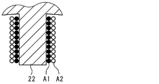
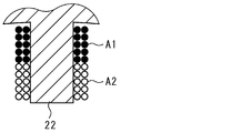
- FIGS. 3 to 5 show simplified examples of how to wind the windings A1, A2 of one pole of the stator 10.
- the windings A1 and A2 may be wound so as to form two layers around the iron core 22, as shown in FIG. 3, so that the iron core 22 is divided into two as shown in FIG. As shown in FIG. 5, they may be wound together, for example, by winding two at the same time.
- the windings A1 and A2, B1 and B2, or C1 and C2 of each layer do not form different poles, but form half of the magnetic fields of all the poles in the phase.
- Each winding A1, A2, B1, B2, C1, C2 has an impedance about twice that of the aluminum winding of each phase of the conventional equivalent motor, and the current value is about that of the conventional winding. Configured to be halved. Therefore, if the copper loss in each of the windings A1, A2, B1, B2, C1, and C2 is set to the same level as that of the conventional winding, the cross-sectional area thereof may be about one-half that of the conventional winding. However, in order to generate the same number of magnetic fluxes as before in each pole, the total length of the windings A1, A2, B1, B2, C1, and C2 is about twice that in the conventional case.
- the individual external terminals 18 are connected to the ends of the lead wires 17 at both ends of the windings A1, A2, B1, B2, C1, and C2 wound in this way.
- the wiring connected to each external terminal 18 is connected to the output terminals U, V, and W of a variable frequency power source (inverter) outside the motor 9, for example.
- the windings A1 and A2, the windings B1 and B2, and the windings C1 and C2 are connected in parallel, respectively, and the windings A1, A2, B1, B2, and C1, C2 is connected to be connected in a delta shape. Since the atmosphere outside the terminal block 16 is highly insulating and non-corrosive air, it can be wired using copper wires or other conductors, and the insulation distance between these conductors is shortened. You can also.
- the windings A1 and A2, the windings B1 and B2, and the windings C1 and C2 are connected in a star shape at the time of starting in order to suppress the starting current.
- the windings A1 and A2, the windings B1 and B2, and the windings C1 and C2 may be connected in series, respectively.
- the pitch of the external terminals 18 in the terminal block 16 is set to other than copper wires. Even if the motor is the same as that of the motor, the gap between the lead wire 17 and the external terminal 18 can be kept large, and a short circuit due to dielectric breakdown (discharge) can be prevented even in an ammonia atmosphere with low insulation.
- the winding of the stator 11 may be wound three times or four times or more, and in that case, three or more terminal blocks 16 may be provided.
- the windings A1, A2, B1, B2, C1, and C2 are each formed by winding a plurality of aluminum wires in which individual aluminum wires are covered with a fluororesin instead of one aluminum stranded wire. May be.
- the rotor casing 4 and the motor casing 8 according to the present invention should not be distinguished by structural integrity, the portion forming the rotor chamber 5 is the rotor casing 4, and the portion forming the motor chamber 9 is the motor casing.
- the portion forming the motor chamber 9 is the motor casing.
Landscapes
- Engineering & Computer Science (AREA)
- Power Engineering (AREA)
- Mechanical Engineering (AREA)
- General Engineering & Computer Science (AREA)
- Windings For Motors And Generators (AREA)
- Insulation, Fastening Of Motor, Generator Windings (AREA)
- Compressor (AREA)
- Applications Or Details Of Rotary Compressors (AREA)
- Motor Or Generator Frames (AREA)
Abstract
Description
2…圧縮機本体
3…モータ
4…ロータケーシング
5…ロータ室
6,7…スクリュロータ
8…モータケーシング
9…モータ室
10…モータ固定子
11…モータ回転子
14…開口
15…スペーサ
16…端子台
17…口出線
18…外部端子
22…鉄心
A1,A2,B1,B2,C1,C2…巻線
Claims (5)
- スクリュロータを収容するロータ室を形成するロータケーシングと、モータの固定子および回転子を収容するモータ室を形成するモータケーシングとが一体に構成されて、圧縮すべき流体の流路と前記モータ室とが連通する密閉型圧縮機において、
前記モータの固定子は、それぞれ、複数の独立した巻線を多重に巻回して形成され、
前記巻線のそれぞれについて個別の外部端子が設けられていることを特徴とする密閉型圧縮機。 - 前記巻線は、アルミニウム線からなることを特徴とする請求項1に記載の密閉型圧縮機。
- 前記巻線は、フッ素樹脂で被覆されていることを特徴とする請求項2に記載の密閉型圧縮機。
- 前記外部端子を複数の端子台に分けて配置したことを特徴とする請求項1に記載の密閉型圧縮機。
- 前記外部端子は、前記巻線の端部を挿入してかしめる圧着端子であることを特徴とする請求項1に記載の密閉型圧縮機。
Priority Applications (4)
| Application Number | Priority Date | Filing Date | Title |
|---|---|---|---|
| US13/808,174 US9062678B2 (en) | 2010-08-03 | 2011-05-30 | Hermetically sealed compressor |
| CN201180038098.4A CN103026071B (zh) | 2010-08-03 | 2011-05-30 | 密闭型压缩机 |
| KR1020137002841A KR101442436B1 (ko) | 2010-08-03 | 2011-05-30 | 밀폐형 압축기 |
| EP11814357.7A EP2602486B1 (en) | 2010-08-03 | 2011-05-30 | Hermetically sealed compressor |
Applications Claiming Priority (2)
| Application Number | Priority Date | Filing Date | Title |
|---|---|---|---|
| JP2010-174412 | 2010-08-03 | ||
| JP2010174412A JP5558961B2 (ja) | 2010-08-03 | 2010-08-03 | 密閉型圧縮機 |
Publications (1)
| Publication Number | Publication Date |
|---|---|
| WO2012017727A1 true WO2012017727A1 (ja) | 2012-02-09 |
Family
ID=45559240
Family Applications (1)
| Application Number | Title | Priority Date | Filing Date |
|---|---|---|---|
| PCT/JP2011/062350 Ceased WO2012017727A1 (ja) | 2010-08-03 | 2011-05-30 | 密閉型圧縮機 |
Country Status (6)
| Country | Link |
|---|---|
| US (1) | US9062678B2 (ja) |
| EP (1) | EP2602486B1 (ja) |
| JP (1) | JP5558961B2 (ja) |
| KR (1) | KR101442436B1 (ja) |
| CN (1) | CN103026071B (ja) |
| WO (1) | WO2012017727A1 (ja) |
Cited By (2)
| Publication number | Priority date | Publication date | Assignee | Title |
|---|---|---|---|---|
| US20140132096A1 (en) * | 2012-11-15 | 2014-05-15 | Sanyo Denki Co., Ltd. | Split-core type motor and method of manufacturing armature of split-core type motor |
| JPWO2015022718A1 (ja) * | 2013-08-12 | 2017-03-02 | 日本精工株式会社 | モータ制御装置、これを使用した電動パワーステアリング装置および車両 |
Families Citing this family (10)
| Publication number | Priority date | Publication date | Assignee | Title |
|---|---|---|---|---|
| JP5558961B2 (ja) | 2010-08-03 | 2014-07-23 | 株式会社神戸製鋼所 | 密閉型圧縮機 |
| JP2014195384A (ja) * | 2013-03-29 | 2014-10-09 | Mitsubishi Electric Corp | 圧縮機用電動機、圧縮機及び冷凍サイクル装置 |
| JP2015039283A (ja) * | 2013-04-02 | 2015-02-26 | アスモ株式会社 | 回転電機 |
| CN104295496B (zh) * | 2014-10-22 | 2018-09-11 | 广东美芝制冷设备有限公司 | 外转子式压缩机 |
| ES2680793B1 (es) * | 2017-01-24 | 2019-06-19 | Ramos Angel Gabriel Ramos | Motor eléctrico de bobina configurable |
| FR3067882B1 (fr) * | 2017-06-16 | 2019-12-06 | Valeo Equipements Electriques Moteur | Stator de machine electrique tournante |
| CN110892155B (zh) * | 2017-07-27 | 2022-01-18 | 三菱电机株式会社 | 压缩机以及空调机的室外机 |
| CN111357172A (zh) * | 2017-11-24 | 2020-06-30 | 三菱电机株式会社 | 电动机、压缩机以及制冷循环装置 |
| WO2020250383A1 (ja) * | 2019-06-13 | 2020-12-17 | 三菱電機株式会社 | 圧縮機および空気調和装置 |
| DE102022123854A1 (de) | 2022-09-16 | 2024-03-21 | ENGIRO GmbH | Stator für eine rotierende Drehfeldmaschine |
Citations (7)
| Publication number | Priority date | Publication date | Assignee | Title |
|---|---|---|---|---|
| JPH07269976A (ja) * | 1994-03-30 | 1995-10-20 | Toshiba Corp | 流体圧縮機および空気調和機 |
| JPH07288996A (ja) * | 1994-04-15 | 1995-10-31 | Meidensha Corp | 大容量インバータ駆動システム |
| JP2001095195A (ja) | 1999-09-22 | 2001-04-06 | Mayekawa Mfg Co Ltd | 密封型電動機などの貫通接続端子の内部接続方法 |
| JP2003319591A (ja) * | 2002-04-24 | 2003-11-07 | Meidensha Corp | 回転電機の巻線 |
| JP2005171943A (ja) | 2003-12-15 | 2005-06-30 | Hitachi Ltd | アンモニア冷媒用密閉形圧縮機 |
| JP2008193785A (ja) * | 2007-02-02 | 2008-08-21 | Mitsubishi Electric Corp | 三相回転電機 |
| JP2009133269A (ja) * | 2007-11-30 | 2009-06-18 | Kobe Steel Ltd | モータおよびスクリュ圧縮機 |
Family Cites Families (7)
| Publication number | Priority date | Publication date | Assignee | Title |
|---|---|---|---|---|
| CA2596635A1 (en) * | 2005-02-07 | 2006-08-17 | Carrier Corporation | Compressor terminal plate |
| JP5291285B2 (ja) * | 2006-07-11 | 2013-09-18 | サンデン株式会社 | 電動圧縮機の密封端子装置 |
| KR100784220B1 (ko) * | 2007-05-08 | 2007-12-10 | 김영국 | 전자석 코일 |
| JP2010166643A (ja) * | 2009-01-13 | 2010-07-29 | Mitsubishi Electric Corp | 密閉型圧縮機及び冷凍サイクル装置 |
| KR200459606Y1 (ko) * | 2009-01-22 | 2012-04-04 | 주식회사 에스 피 지 | 전기모터용 전기코일 |
| JP4998527B2 (ja) * | 2009-09-08 | 2012-08-15 | 株式会社豊田自動織機 | 電動圧縮機 |
| JP5558961B2 (ja) | 2010-08-03 | 2014-07-23 | 株式会社神戸製鋼所 | 密閉型圧縮機 |
-
2010
- 2010-08-03 JP JP2010174412A patent/JP5558961B2/ja active Active
-
2011
- 2011-05-30 EP EP11814357.7A patent/EP2602486B1/en active Active
- 2011-05-30 WO PCT/JP2011/062350 patent/WO2012017727A1/ja not_active Ceased
- 2011-05-30 US US13/808,174 patent/US9062678B2/en not_active Expired - Fee Related
- 2011-05-30 CN CN201180038098.4A patent/CN103026071B/zh active Active
- 2011-05-30 KR KR1020137002841A patent/KR101442436B1/ko not_active Expired - Fee Related
Patent Citations (7)
| Publication number | Priority date | Publication date | Assignee | Title |
|---|---|---|---|---|
| JPH07269976A (ja) * | 1994-03-30 | 1995-10-20 | Toshiba Corp | 流体圧縮機および空気調和機 |
| JPH07288996A (ja) * | 1994-04-15 | 1995-10-31 | Meidensha Corp | 大容量インバータ駆動システム |
| JP2001095195A (ja) | 1999-09-22 | 2001-04-06 | Mayekawa Mfg Co Ltd | 密封型電動機などの貫通接続端子の内部接続方法 |
| JP2003319591A (ja) * | 2002-04-24 | 2003-11-07 | Meidensha Corp | 回転電機の巻線 |
| JP2005171943A (ja) | 2003-12-15 | 2005-06-30 | Hitachi Ltd | アンモニア冷媒用密閉形圧縮機 |
| JP2008193785A (ja) * | 2007-02-02 | 2008-08-21 | Mitsubishi Electric Corp | 三相回転電機 |
| JP2009133269A (ja) * | 2007-11-30 | 2009-06-18 | Kobe Steel Ltd | モータおよびスクリュ圧縮機 |
Cited By (3)
| Publication number | Priority date | Publication date | Assignee | Title |
|---|---|---|---|---|
| US20140132096A1 (en) * | 2012-11-15 | 2014-05-15 | Sanyo Denki Co., Ltd. | Split-core type motor and method of manufacturing armature of split-core type motor |
| US9871421B2 (en) * | 2012-11-15 | 2018-01-16 | Sanyo Denki Co., Ltd. | Split-core type motor and method of manufacturing armature of split-core type motor |
| JPWO2015022718A1 (ja) * | 2013-08-12 | 2017-03-02 | 日本精工株式会社 | モータ制御装置、これを使用した電動パワーステアリング装置および車両 |
Also Published As
| Publication number | Publication date |
|---|---|
| EP2602486A1 (en) | 2013-06-12 |
| US20130121815A1 (en) | 2013-05-16 |
| KR20130050350A (ko) | 2013-05-15 |
| US9062678B2 (en) | 2015-06-23 |
| JP2012036733A (ja) | 2012-02-23 |
| CN103026071B (zh) | 2015-08-05 |
| CN103026071A (zh) | 2013-04-03 |
| EP2602486B1 (en) | 2019-08-07 |
| JP5558961B2 (ja) | 2014-07-23 |
| EP2602486A4 (en) | 2017-08-30 |
| KR101442436B1 (ko) | 2014-09-17 |
Similar Documents
| Publication | Publication Date | Title |
|---|---|---|
| JP5558961B2 (ja) | 密閉型圧縮機 | |
| US8274190B2 (en) | Electric machine rotor bar and method of making same | |
| JP4998527B2 (ja) | 電動圧縮機 | |
| JP7004766B2 (ja) | 絶縁装置を備える圧縮機の駆動装置 | |
| JP7004688B2 (ja) | 圧縮機駆動装置及びその製造方法 | |
| CN112564326B (zh) | 定子、电机及车辆 | |
| US20220045569A1 (en) | Motor and compressor | |
| JPWO2014156019A1 (ja) | 電動機の電線接続方法 | |
| JP2008514173A (ja) | 平角線巻線を有する永久磁石同期機 | |
| US20140210302A1 (en) | Motor for use in refrigerant environment | |
| EP2914851B1 (en) | Semi-hermetic compressor motor for ammonia service | |
| KR101550100B1 (ko) | 전동기의 고정자, 전동기, 밀폐형 압축기 및 회전 기계 | |
| US20220324298A1 (en) | Device for driving a compressor, and method for manufacturing the device | |
| JP2009133269A (ja) | モータおよびスクリュ圧縮機 | |
| US9991692B2 (en) | Method and apparatus for sealing motor terminals | |
| JP6890075B2 (ja) | 回転電機 | |
| CN209267283U (zh) | 电机定子、电机和变频压缩机 | |
| WO2023082263A1 (zh) | 电机定子、变频电机及电机定子的制造方法 | |
| TH72315B (th) | คอมเพรสเซอร์ที่ถูกปิดผนึกแบบหุ้มปิดสนิท | |
| WO2021056853A1 (zh) | 定子、电机及车辆 | |
| JP2006166553A (ja) | 回転電機 | |
| PL218725B1 (pl) | Pojedyncza fazowa puszka przyłączeniowa |
Legal Events
| Date | Code | Title | Description |
|---|---|---|---|
| WWE | Wipo information: entry into national phase |
Ref document number: 201180038098.4 Country of ref document: CN |
|
| 121 | Ep: the epo has been informed by wipo that ep was designated in this application |
Ref document number: 11814357 Country of ref document: EP Kind code of ref document: A1 |
|
| WWE | Wipo information: entry into national phase |
Ref document number: 2011814357 Country of ref document: EP |
|
| WWE | Wipo information: entry into national phase |
Ref document number: 13808174 Country of ref document: US |
|
| ENP | Entry into the national phase |
Ref document number: 20137002841 Country of ref document: KR Kind code of ref document: A |
|
| NENP | Non-entry into the national phase |
Ref country code: DE |