WO2012017903A1 - センサ付き真空断熱パネルとそのパネルを利用した断熱容器 - Google Patents
センサ付き真空断熱パネルとそのパネルを利用した断熱容器 Download PDFInfo
- Publication number
- WO2012017903A1 WO2012017903A1 PCT/JP2011/067199 JP2011067199W WO2012017903A1 WO 2012017903 A1 WO2012017903 A1 WO 2012017903A1 JP 2011067199 W JP2011067199 W JP 2011067199W WO 2012017903 A1 WO2012017903 A1 WO 2012017903A1
- Authority
- WO
- WIPO (PCT)
- Prior art keywords
- sensor
- vacuum
- insulation panel
- battery
- vacuum insulation
- Prior art date
- Legal status (The legal status is an assumption and is not a legal conclusion. Google has not performed a legal analysis and makes no representation as to the accuracy of the status listed.)
- Ceased
Links
Images



Classifications
-
- F—MECHANICAL ENGINEERING; LIGHTING; HEATING; WEAPONS; BLASTING
- F16—ENGINEERING ELEMENTS AND UNITS; GENERAL MEASURES FOR PRODUCING AND MAINTAINING EFFECTIVE FUNCTIONING OF MACHINES OR INSTALLATIONS; THERMAL INSULATION IN GENERAL
- F16L—PIPES; JOINTS OR FITTINGS FOR PIPES; SUPPORTS FOR PIPES, CABLES OR PROTECTIVE TUBING; MEANS FOR THERMAL INSULATION IN GENERAL
- F16L59/00—Thermal insulation in general
- F16L59/06—Arrangements using an air layer or vacuum
- F16L59/065—Arrangements using an air layer or vacuum using vacuum
-
- G—PHYSICS
- G01—MEASURING; TESTING
- G01K—MEASURING TEMPERATURE; MEASURING QUANTITY OF HEAT; THERMALLY-SENSITIVE ELEMENTS NOT OTHERWISE PROVIDED FOR
- G01K13/00—Thermometers specially adapted for specific purposes
- G01K13/10—Thermometers specially adapted for specific purposes for measuring temperature within piled or stacked materials
-
- F—MECHANICAL ENGINEERING; LIGHTING; HEATING; WEAPONS; BLASTING
- F25—REFRIGERATION OR COOLING; COMBINED HEATING AND REFRIGERATION SYSTEMS; HEAT PUMP SYSTEMS; MANUFACTURE OR STORAGE OF ICE; LIQUEFACTION SOLIDIFICATION OF GASES
- F25D—REFRIGERATORS; COLD ROOMS; ICE-BOXES; COOLING OR FREEZING APPARATUS NOT OTHERWISE PROVIDED FOR
- F25D2201/00—Insulation
- F25D2201/10—Insulation with respect to heat
- F25D2201/14—Insulation with respect to heat using subatmospheric pressure
Definitions
- a heat insulating core material is covered with a covering material, and various sensors such as a temperature sensor, a vacuum sensor, and an acceleration sensor inside the covering material, a storage unit capable of storing data detected by these sensors, sensors and storage
- various sensors such as a temperature sensor, a vacuum sensor, and an acceleration sensor inside the covering material
- a storage unit capable of storing data detected by these sensors, sensors and storage
- the thermal insulation container accommodates various articles that require cold storage such as food, food, cosmetics, medicine, etc. It can be used for storage and transportation.
- heat insulating materials having high heat insulating performance, including expanded polystyrene, as heat insulating materials.
- a heat insulating material is used as a core material, and the outer periphery is covered with a gas barrier material, and the inside of the material is decompressed to a high vacuum state (hereinafter referred to as "vacuum state"), and the material is covered.
- vacuum state a high vacuum state
- vacuum heat insulating material in which the opening of the material is sealed by means of heat sealing or the like to maintain a vacuum state.
- the vacuum heat insulating material improves the heat insulating performance by setting it in a vacuum state.
- the thermal conductivity of the vacuum heat insulating material is about 0.002 to 0.01 w / mk, and the heat insulating performance is remarkable as compared with 0.02 to 0.03 w / mk of expanded polystyrene and 0.02 w / mk of air.
- the thermal conductivity of expanded polystyrene is about 0.02 to 0.03 w / mk, which is almost the same as that of air, and it is not particularly excellent in heat insulation.
- the cooling capacity of dry ice and a cold-storage agent falls with time, it was not able to cool a cold-retentioned article over a long time in the conventional cold-storing container. Even when delivering by car, it may take longer than expected to complete the delivery depending on traffic conditions. For this reason, in the cold insulation container made from a heat insulating material, sufficient cold insulation was difficult.
- the subject of the present invention is excellent in heat insulation, and can detect the temperature around the panel, the degree of vacuum in the panel, the acceleration of the panel during movement, etc., and can perform temperature control around the panel, vacuum control of the panel, vibration control, etc.
- An object of the present invention is to provide a vacuum insulation panel with a sensor and an insulation container using the vacuum insulation panel with the sensor.
- the vacuum insulation panel with a sensor is a vacuum insulation panel in which a heat insulating core material is covered with a gas barrier covering material and the inside of the covering material is in a vacuum state, the battery and at least the outside temperature of the covering material.
- the temperature sensor capable of detecting the temperature
- the communication unit capable of communicating with the outside the detection data by the temperature sensor wirelessly or by wire and / or the data logger capable of storing the detection data are individually or unitized and the outside It was installed inside the material.
- the vacuum insulation panel with sensor also includes one or more of a vacuum sensor, an acceleration sensor, and a humidity sensor, and these sensors may be used individually or as temperature sensors, batteries, data loggers Unitized with any one or two or more and installed inside the cover material, and the data logger can store detection data of one or more of the temperature sensor, vacuum sensor, acceleration sensor, humidity sensor You can also.
- the detection data stored in the data logger can be communicated with the outside by a communication unit or read by an external device.
- communication includes wirelessly reading detection data stored in a data logger by an external device and transmitting it from a communication unit.
- One or more of a temperature sensor, a communication unit, a data logger, a battery, a vacuum sensor, an acceleration sensor, and a humidity sensor provided inside the outer cover material in a recess or in the core material provided in a part of the core material It can be provided on the surface.
- the covering material is formed by combining a thermally conductive material and a radio wave permeable material, and the range covering the communication section in the covering material is a radio wave permeable material, and the range covering the temperature sensor is a thermally conductive material.
- a connector which can be connected to the communication unit or the data logger by wire can be provided on the outside of the cover material.
- the battery may be rechargeable, and a charging terminal capable of connecting a charging power source to the battery may be provided on the outside of the cover material.
- the battery may be contactless rechargeable.
- the heat insulation container according to the present invention is a heat insulation container comprising a container body having a bottom and a peripheral wall and a lid, wherein any one or more of the bottom, the peripheral wall and the lid is inside or outside. Are arranged.
- the heat insulation container of the present invention is a heat insulation container having a container body having a bottom and a peripheral wall and a lid, wherein any one or more of the bottom, the peripheral wall and the lid is formed of any of the above-described vacuum insulation panels with sensors. You can also.
- the cover material of the sensor-equipped vacuum insulation panel used for any one or more of the bottom, the peripheral wall and the lid is a plate made of a hard material, and the plate-like cover is the bottom, the peripheral wall , Which are disposed toward the outside of the lid.
- the sensor-equipped vacuum insulation panel of the present invention has the following effects. (1) Since the core material is a heat insulating material and the inside of the outer covering material covering the outer periphery of the core material is in a vacuum state, a panel having a good heat insulating property is obtained. (2) Since various sensors and a communication unit are provided, detection data detected by the sensor can be transmitted / received (communicated) with a communication device of an external management center by the communication unit, and heat insulation using a vacuum insulation panel with a sensor Temperature control in the container can be performed in real time by the control center. (3) Since the data logger is provided, the detection data of various sensors stored in the data logger can be read by the reader to perform temperature management in the heat insulation container.
- the vacuum state of the sensor-equipped vacuum insulation panel can be monitored, and the vacuum state can be maintained and managed.
- two or more of various components such as a temperature sensor, a vacuum sensor, an acceleration sensor, a humidity sensor, a communication unit, a data logger, and a battery are unitized, housing in the outer cover material becomes easy.
- the battery is provided inside the cover material and in the recess of the core material, the battery will not be exposed to low temperatures even when used in a low temperature environment, and the battery will not easily deteriorate.
- the area covering the communication unit in the cover material is made of radio wave transmission material, communication with the outside becomes reliable without the communication unit being shielded.
- the area covering the temperature sensor in the outer cover material is made of a heat conductive material, temperature detection with the temperature sensor can be performed reliably.
- the connection tool capable of wired connection with the communication unit is provided on the outside of the cover material, wired communication can be performed simply by connecting the external device to the connection tool.
- the communication unit is wireless, temperature control of the heat insulation container can be performed in real time even if the heat insulation container formed of the sensor-equipped vacuum heat insulation panel of the present invention is located remotely from the control center.
- the battery is rechargeable and the charging terminal to which the charging power can be connected is provided on the outside of the cover material, the battery can be charged and used repeatedly.
- the battery is of a non-contact charge type, charging becomes easy.
- the covering material for covering the core material is waterproof, cleaning can be facilitated.
- the heat insulation container of this invention has the following effects. (1) Since the sensor-equipped vacuum insulation panel of the present invention is used, it is excellent in thermal insulation, and the amount of dry ice and cold storage agent bundled in the thermal insulation container can be made smaller than before. (2) Since detection data of various sensors can be obtained and temperature control, vacuum control, vibration control, humidity control, etc. of the heat insulation container can be carried out, quality control of a product requiring cooling in the heat insulation container can also be carried out. .
- the battery Since the battery is installed in the vacuum insulation panel with a sensor, the battery deteriorates even when used in a high humidity environment where low temperature condensation occurs, a low temperature environment, for example, in a heat insulation container containing products requiring insulation Because it is difficult to use and long-term use becomes possible, detection with various sensors, temperature control, vacuum control, acceleration control, and the like can be reliably performed over a long period of time.
- the vacuum insulation panel with a sensor is provided not only on the bottom and the peripheral wall of the container main body but also on the inner surface of the lid (top plate), the heat insulation effect is improved, and cold storage of the required products can be ensured.
- the present insulation container can be effectively used without discarding, which is economical There is no negative impact on the environment.
- the surface of the sensor-equipped vacuum insulation panel is covered with the covering material, it can be easily cleaned, and the hygiene maintenance and management in the insulation container can be facilitated.
- a sensor-equipped vacuum insulation panel equipped with an acceleration sensor it is possible to grasp the vibration state of the insulation container during transportation in a car or the like, and it is useful for quality control of products requiring cooling in the insulation container.
- FIG. 1 is a perspective view which shows an example of a heat insulation container, (b) is sectional drawing of (a).
- Sectional drawing which shows an example of the heat insulation container using the vacuum insulation panel with a sensor of this invention.
- (A) is a longitudinal cross-sectional view which shows the other example of the heat insulation container of this invention
- (b) is a cross-sectional view of a container main body.
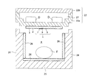
- Sectional drawing of the example which is the heat insulation container of this invention, and was made to be able to accommodate dry ice etc. in a lid
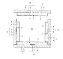
- Sectional drawing which shows the heat insulation container using the vacuum-insulation panel with a sensor which made the jacket material plate shape.
- Embodiment 1 An example of the embodiment of the sensor-equipped vacuum insulation panel 1 of the present invention will be described based on the drawings.
- the vacuum insulation panel 1 with a sensor shown in FIGS. 1 (a) to 1 (d) has a vacuum sensor 4 mounted on a substrate 11 and a temperature sensor, the outer periphery of a heat insulating plate-like core 2 being covered with a jacket 3
- various sensors 5 such as a humidity sensor and an acceleration sensor, a data logger (storage unit) 6, a communication unit (transmission / reception unit) 7, a battery 8 and an antenna 9 provided inside the cover material 3
- the inside of 3 is evacuated (reduced pressure) to a vacuum state.
- various sensors 5, the data logger 6, the communication unit 7, the battery 8 and the antenna 9, either existing ones or newly developed ones can be used.
- the substrate 11 it is possible to use a single substrate of a flexible film or a laminated substrate in which a large number of flexible films are laminated, or a rigid substrate of glass epoxy, bakelite, or the like. In the following description, the case where temperature sensors are used as the various sensors 5 will be described as an example.
- voids voids
- voids porous one having many voids, holes and the like inside is suitable, for example, one made of urethane, powdered silica, glass wool, ceramic fiber, rock wool etc. Examples include those made of fiber materials.
- styrohomes can also be used, they have the disadvantage of being fragile, so care may be required depending on the situation of use. Glass wool has the characteristic of being hard to break.
- the material, shape, size, thickness and the like of the heat insulating material are designed in accordance with the application of the vacuum insulation panel 1 with a sensor.
- the jacket material 3 is made of a material having a high gas barrier property in order to keep the inside of the casing in a vacuum state.
- materials having high gas barrier properties stainless steel, aluminum, metals such as iron, single materials such as plastics (resins), composite materials obtained by laminating metal foil and plastic film, composite materials obtained by vapor depositing metal on plastic, metal sheet Composite material of laminated structure in which resin sheets are laminated, composite material made of resin fiber or natural fiber cloth such as woven fabric or non-woven fabric and gas barrier resin or metal foil film or sheet etc. Etc. can be used.
- the material, thickness, shape, size, composite structure, strength and the like of the cover material 3 are designed in accordance with the application of the vacuum insulation panel 1 with a sensor.
- the covering material 3 may be a film or a sheet, and the covering material 3 may cover the outer periphery of the core 2 as shown in FIGS. 1 (a) to 1 (c). Can be coated with a film-like covering material 3 and the opposite side can be covered with a sheet-like covering material 3.
- a plate-like covering material 3 having gas barrier properties such as a metal plate or a resin plate is disposed on one side of the core 2 (the lower surface in FIG. 1D).
- the outer periphery of the core material 2 can also be covered by covering the film-like outer covering material 3 on the outer peripheral surface (the upper surface and the side surface in FIG. 1D).
- a plate-like outer covering material 3 as shown in FIG. 1D is disposed on both sides of the core material 2, and the sheet-like or film-like outer covering material 3 It can also be coated. In either case, the inside of the jacket material 3 is vacuumed to a vacuum.
- the outer covering material 3 may be made of a double material having the same material or different structure (or having different gas barrier properties). By double coating, even if one of the outer covering materials 3 is damaged, the vacuum state inside the other outer covering material 3 is secured.
- the outer covering material 3 using a metal material such as aluminum has a characteristic of high thermal conductivity, but also has shielding properties (radio wave shielding properties). If the thermal conductivity is high, it is suitable for temperature detection with a temperature sensor provided on the inside of the sheath material 3. However, if the shield characteristics are good, data detected by various sensors are communicated with the outside through the communication unit 7 or an external device Since it is not suitable for reading at this time, it is desirable that the outside portion of the communication unit 7 and the antenna 9 in the covering material 3 be made of a radio wave transmitting material having gas barrier properties but no shielding properties.
- the outer cover material 3 may be made of resin.
- the resin not only has gas barrier properties but is not suitable for communication and data reading because it has no radio wave shielding properties, but it has low thermal conductivity and measures the ambient temperature with the temperature sensor 5 provided in the outer cover material 3 Not suitable for
- a metal with high thermal conductivity, such as aluminum in the range covering the temperature sensor 5 in the outer covering material 3 and use a resin without radio wave shielding in the range covering the communication unit 7 .
- the jacket material 3 can be maintained in a vacuum state by evacuating the inside (including the inside of the core material 2) to a vacuum state and then sealing (for example, heat sealing) the vacuumed opening, so
- the material 3 is easily heat-sealed in combination with a heat-sealable material.
- a combination of metal sheets such as aluminum, a plate, a film, a sheet, etc. by laminating or depositing PET (Polyethylene Terephthalate) is suitable. PET materials are heat-welded at about 90 ° C., and various sensors do not usually melt up to about 200 ° C., which is suitable for the sensors.
- the core material 2 and the sheath material 3 are not limited to those described above, and materials of other materials conventionally used as vacuum heat insulating materials can be used, and in particular, the materials can be made larger in size and can be further bent. When designed to have a thickness, it is possible to fold the single sensor-equipped vacuum insulation panel 1 to produce an insulation container 20 having a container body 21 and a lid 22.
- the sensor-equipped vacuum heat insulation panel 1 has excellent heat insulation performance by making the inside of the outer cover material 3 in a vacuum state.
- the thermal conductivity of the sensor-equipped vacuum insulation panel 1 is 0.002 to 0.01 w / mk, compared with 0.02 to 0.03 w / mk of polystyrene foam and 0.02 w / mk of air. It turns out that the heat insulation performance is remarkable.
- vacuum sensor There are various types of vacuum sensors 4 such as Pirani vacuum gauge, diaphragm vacuum gauge, capacitance type vacuum sensor, micro mechanical vacuum sensor and so on.
- various vacuum sensors can be used as long as they can detect the vacuum state inside the outer cover material 3.
- the vacuum sensor 4 is preferably as small and thin as possible in order to be housed in the core material 2 or in the jacket material 3. Since a vacuum state means a reduced pressure state, for example, a pressure sensor can be used.
- the vacuum sensor 4 is operated by the power supplied from the battery B, the pressure inside the jacket material 3 is detected by the vacuum sensor 4, and the detected current (voltage) is amplified by the amplifier A.
- the output voltage By comparing the output voltage with the appropriate vacuum state (appropriate pressure in the jacket material 3: reference pressure) Pa required by the sensor-equipped vacuum insulation panel 1 of the present invention in the comparator C, It can be determined whether or not the inside is maintained at an appropriate vacuum state.
- the detected pressure is displayed on the digital meter M so that the vacuum state inside the outer cover material 3 can be confirmed.
- the solenoid valve of the vacuum pump P can be opened by the relay R, and the inside of the envelope material 3 can be depressurized by the vacuum pump P.
- the entire vacuum sensor 4 may be provided in the outer covering material 3, but may be partially protruded to the outside of the outer covering material 3 and attached. In either case, it is attached so that the vacuum state in the sheath material 3 is not impaired.
- the battery B of FIG. 3 is outside the cover material 3, the battery B always uses the battery 8 in the sensor-equipped vacuum insulation panel 1 shown in FIG. Can also detect the degree of vacuum.
- the vacuum data detected by the vacuum sensor 4 is wirelessly communicated from the communication unit 7 inside the cover material 3 to the external control center, data processing is performed in the control center, and the vacuum condition is confirmed. Can manage the vacuum state of The communication can also be performed by wire.
- the antenna 9 shown in FIG. 1 (a) can be used.
- a connector that can be electrically connected to an external device or other connecting device (connector) is provided outside the covering material 3 and wired communication is performed with the external device connected thereto. be able to.
- the various sensors 5 used in the present invention may be separately prepared as dedicated ones, but commercially available ones may also be used.
- the temperature sensor 5 can detect at least the ambient temperature outside the sensor-equipped vacuum insulation panel 1, and can also detect the temperature in the sensor-equipped vacuum insulation panel 1, if necessary.
- the acceleration sensor detects the vibration of the sensor-equipped vacuum insulation panel 1, and the sensor-equipped vacuum insulation panel 1 is used, for example, for the thermal insulation container 20, and the required insulation item F is accommodated in the thermal insulation container 20 to use When transporting, it is possible to grasp the vibration state of the item requiring cooling F in the heat insulating container 20 and use it for the quality control of the item requiring cooling F.
- the humidity sensor can detect the moisture when the moisture intrudes into the jacket material 3 from the outside due to deterioration or breakage of the gas barrier properties of the jacket material 3.
- the vacuum state of the covering material 3 can also be managed by detecting this humidity.
- the communication unit 7 provided inside the outer covering material 3 can transmit and receive (communicate) various data detected by the sensor at any time or in real time with the external management center or other external devices.
- the data stored in the memory may be transmitted and received (communicated) as needed, and a general-purpose compact transmitter-receiver can be used. If the data logger 6 can store detection data of various sensors and can read the data by a personal computer or the like, the data logger 6 can be used as the communication unit 7. In that case, the dedicated communication unit 7 It becomes unnecessary.
- the data logger 6 of the present invention can use a specially developed data logger or a general-purpose data logger.
- General-purpose data loggers include temperature data loggers, humidity data loggers, temperature and humidity data loggers, vibration data loggers, and GPS (global positioning system) data loggers.
- the data logger 6 can not only store data detected by other sensors, but also can detect its own temperature and humidity and store its detected data, and can store data detected by other sensors. In addition, there are some that can detect two or more data, such as temperature and humidity, and store those data.
- vacuum data for example, pressure data
- temperature data detected by the temperature sensor 5 are stored in the data logger 6 provided inside the cover material 3 and stored data Are transmitted to an external management center by the communication unit 7, read by a reader (reader), read (collected) by a personal computer, etc., and the vacuum state, temperature, etc. are confirmed. It is also possible to manage the cold storage condition of the item F requiring insulation in the heat insulation container 20 using 1.
- a battery 8 is provided as a power source for operating the vacuum sensor 4, various sensors 5 such as a temperature sensor and a humidity sensor, the data logger 6, the communication unit 7 and the like.
- various sensors 5 such as a temperature sensor and a humidity sensor, the data logger 6, the communication unit 7 and the like.
- a lithium battery or other long-life battery can be used.
- the battery may be rechargeable or non-rechargeable.
- a charging power supply connector for example, an outlet
- charging is provided outside the covering material 3 and charging can be performed by connecting a power supply thereto.
- non-contact charging for example, a charging method using electromagnetic waves for charging has also been studied, and is expected to be put to practical use, it is possible to use non-contact rechargeable batteries.
- the present invention relates to a core material 2 and a sheath material having heat insulating properties of the battery. By providing the inside of 3, it can be isolated from a low temperature environment or a high humidity environment.
- the vacuum sensor 4, the temperature sensor 5, the data logger 6, the humidity sensor, the acceleration sensor, the communication unit 7, the battery 8, etc. used in the present invention can be individually provided inside the core 2 or the jacket 3 It is easy to accommodate the inside of the core material 2 and the outer covering material 3 when it is united into one.
- FIGS. 4A and 4B show an example of the unit 10, and the vacuum sensor 4, the temperature sensor 5, the data logger 6, and the communication unit 7 are mounted on one side of the substrate 11 on which the electrical wiring and the antenna 9 are displayed.
- a battery holder 14 is provided on the opposite side of the substrate 11, and the battery holder 14 accommodates a button-type battery 8.
- the substrate 11 is a hard substrate.
- FIG. 4C shows another example of the unit 10, in which the temperature sensor 5 is provided on the front end side (upper side of FIG. 4C) of the flexible film substrate 11, and the communication unit 7 is provided on the other end side of the flexible film substrate 11.
- a button type battery 8 is provided at the end of the flexible film substrate 11.
- components for communication such as the temperature sensor 5, the communication unit 7, the antenna 9 and the like have been miniaturized. It is desirable that the sensor used in the sensor-equipped vacuum insulation panel 1 of the present invention is also compact.
- the combination of parts to be unitized can be appropriately selected, and can be a combination other than the combination of the parts.
- FIG. 1A shows a recess in which a core 10 is provided with a unit 10 in which a vacuum sensor 4, a temperature sensor 5, a data logger 6 and a communication unit 7 are provided on the upper surface of a substrate 11 and a battery 8 is provided on the lower surface of the substrate 11. It is a case where it is accommodated and fixed within 15.
- the unit 10 is accommodated in the recess 15 provided in the core material 2 and thereafter the outer periphery of the core material 2 is covered with the covering material 3 and the inside of the covering material 3 is evacuated to a predetermined degree of vacuum (reference pressure ).
- a filler with high thermal conductivity can be injected into the space in the recess 15 containing the unit 10 before covering the covering material 3 or it can be left as a space as it is.
- the battery 8 is disposed substantially at the center in the thickness direction of the core material 2 so as to be less affected by the external low temperature and high humidity environment.
- the vacuum sensor 4, the data logger 6, the communication unit 7 and the battery 8 are provided on the lower surface of the substrate 11, and the unit 10 provided with the temperature sensor 5 on the upper surface is the core material 2 with the temperature sensor 5 facing upward. It arrange
- FIG. By arranging in this manner, the external temperature can be easily detected by the temperature sensor 5, and the vacuum sensor 4, the data logger 6, the communication unit 7, and the battery 8 are less likely to be damaged. In this case, since the unit 10 is covered only with the covering material 3, it is preferable in terms of temperature measurement and communication. Further, since the battery 8 is disposed in the core material 2, it is protected from the external low temperature and high humidity environment.
- the vacuum sensor 4, the data logger 6, the communication unit 7, and the battery 8 are disposed in the core 2 with the substrate 11 up, and the substrate 11 is provided in the core 2.
- the temperature sensor 5 attached to the lead-out portion is disposed on the back surface side of the core material 2 and is led out to the opposite side in the thickness direction of the core material 2 (the lower side in FIG. 1C).
- the plate-like outer covering material 3 is disposed, and the outer covering material 3 of the resin sheet is covered from the upper surface of the core material 2 to the side surface, and the outer covering material 3 is closely attached to the plate-like outer covering material 3. And the inside of the plate-like covering material 3 and the sheet-like covering material 3 is in a vacuum state.
- the plate-like covering material 3 can be a metal plate or a resin plate.
- the sheet-like covering material 3 placed on the core material 2 of FIG. 1 (d) is replaced with the plate-like covering material 3
- the space between the two outer covering materials 3 may be sealed with a sheet-like outer covering material 3 and then the inside thereof may be in a vacuum state.
- a unit 10 having a temperature sensor 5, a battery 8 and a communication unit 7 mounted on a substrate 11 is disposed and fixed on a core 2, and the core 2 is made of an outer covering 3 from outside the unit 10. And the inside of the cover material 3 is in a vacuum state.
- the temperature sensor 5, the communication unit 7, and the antenna 9 are covered only with the jacket 3, it is preferable in terms of temperature detection and communication.
- the substrate 11, the temperature sensor 5, the communication unit 7, and the antenna 9 in the unit 10 are disposed on the surface of the core 2, the battery 8 is disposed in the core 2, and the inside of the outer cover 3 is It is in a vacuum state.
- the communication unit 7 of the unit 10, the antenna 9 and the battery 8 are disposed on the upper surface of the core 2, and the through hole provided in the core 2 so as to communicate the substrate 11 with the back surface (lower surface) of the core 2.
- the temperature sensor 5 provided at the tip of the substrate 11 is disposed on the back surface of the core material 2 so as to draw the inside of the cover material 3 in a vacuum state.
- the inside of the heat insulating material is also reduced in pressure by reducing the pressure in the inside of the outer covering material 3 with a vacuum device and bringing it into a vacuum. Since it is difficult to maintain the subsequent vacuum state if the heat insulating material is moistened, it is desirable to carry out the emptying operation (decompression operation) in the outer covering material 3 in a dry environment such as carrying out dry air.
- the vacuum state is not limited to an absolute vacuum state, but refers to a state in which the degree of vacuum is high, and means a state in which the degree of vacuum is about 1 to 200 Pa, preferably about 1 to 100 Pa.
- the heat insulation container 20 shown in FIGS. 5A and 5B can store and convey the item F requiring insulation requiring storage, and includes a container body 21 and a lid 22.
- the container main body 21 and the lid 22 can be newly prepared, but the cold storage container currently used can also be used as it is.
- the container body 21 and the lid 22 of the existing cold insulation container are made of heat insulating material, and representatively, they are made of expanded polystyrene.
- the lid 22 shown in FIGS. 5A and 5B can be fitted over the container body 21 so that the container space 21 in the container body 21 is substantially sealed when the container body 21 is covered. It is possible to insulate (insulate) the product F requiring insulation (FIG. 6) stored in the space 23 from external heat.
- the sensor-equipped vacuum insulation panel 1 of the present invention is disposed on the inner side of the four circumferences (four sheets) of the peripheral wall 24 of the container body 21 and the inner side of the lid 22.
- a vacuum insulation panel (sensorless vacuum insulation panel) 26 not provided is disposed.
- the sensor-equipped vacuum insulation panel 1 and the sensorless vacuum insulation panel 26 may be fixed to the inner surface of each wall or may be disposed without being fixed.
- the temperature sensor 5 is disposed on the side of the housing space 23 and the battery 8 is on the outside, which is suitable for temperature detection by the temperature sensor 5, and the battery 8 is separated from the housing space 23 of low temperature and high humidity. The deterioration is to be suppressed.
- the inside of the housing space 23 is thermally insulated from the outside, and the temperature data detected by the temperature sensor 5 of the sensor-equipped vacuum insulation panel 1
- the temperature in the accommodation space 23 can be managed by utilizing it.
- the vacuum state of the inside of the cover material 3 is detected by the vacuum sensor 4, and the vacuum state of the sensor-equipped vacuum insulation panel 1 can be monitored and vacuum controlled. Since the battery 8 installed inside the sensor-equipped vacuum insulation panel 1 is thermally insulated from the housing space 23, the problem of deterioration (shortening of life) due to a low temperature environment and a high humidity environment can be solved.
- the heat insulating container including the temperature and humidity in the accommodation space 23 It is possible to monitor the condition at the time of movement of 20 and to control the quality of the item F requiring insulation in the heat insulation container 20.
- the fitting recess 30 of the sensor-equipped vacuum insulation panel 1 provided on the inner surface of the peripheral wall 24 and the fitting projection 31 of the sensor-less vacuum insulation panel 26 provided on the bottom 25 are fitted.
- the heat insulating panels 1 and 26 do not necessarily have to be fitted, and may simply be butted.
- the heat insulation container 20 of the present invention has a sensor-equipped vacuum insulation panel 1 or a sensor-less vacuum insulation panel 26 on the inner surface side of the container body 21 and lid 22 newly prepared.
- the heat insulation container 20 of the present invention comprises a lid 22 composed of a lid body 22 a and a cover 22 b which can be detached in a sealed state, and a lid space 27 is provided in the lid body 22 a.
- the dry ice D or the like is accommodated, and the vacuum insulation panel 1 with a sensor is attached to the inner surface of the lid body 22a.
- the sensorless vacuum heat insulation panel 26 can be attached to the inner surface of the lid body 22a.
- the heat insulating container 20 of the present invention does not use a container made of a heat insulating material as shown in FIG. 6, but as shown in FIG. 9, the vacuum heat insulating panel with sensor of FIG. It can also consist of only one.
- the sensor-equipped vacuum insulation panel 1 shown in FIG. 1 (d) is used for the bottom 25, the peripheral wall 24, and the lid 22, and the thick plate-like outer covering material 3 is disposed outside.
- the plate-like outer covering material 3 can be placed inside.
- all of the bottom 25, the peripheral wall 24, and the lid 22 can be used as the sensor-equipped vacuum insulation panel 1 of FIG. It is also possible to make it the panel 26, and its arrangement and combination can be designed arbitrarily.
- the sensor-equipped vacuum insulation panel 1 of the present invention can also be used as a building material such as a floor material or an outer wall material of a house.
- the heat insulation container 20 according to the present invention can be applied to home delivery of food and the like, as well as for transportation of all the products F requiring cosmetics such as cosmetics, medicines, electronic parts, precision instruments, organs and the like.
- Vacuum insulation panel with sensor 2: core material, 3: jacket material, 4: Vacuum sensor, 5: Various sensors (temperature sensor), 6: Data logger (storage unit), 7: communication unit (transmission / reception unit), 8: battery, 9: antenna, 10: unit, 11: substrate, 14: battery holder, 15: recess, 20: heat insulation container, 21: container body, 22: lid, 22a: lid body, 22b: cover, 23: accommodation space 24: peripheral wall 25: bottom 26: sensorless vacuum insulation panel, 27: lid space, 30: fitting recess, 31: fitting protrusion, A: Amplifier, B: Battery, C: Comparator, D: Dry ice, F: Cold storage required, M: Digital meter, P: Vacuum pump, Pa: Reference pressure (reference value), R: Relay
Landscapes
- Engineering & Computer Science (AREA)
- General Engineering & Computer Science (AREA)
- Mechanical Engineering (AREA)
- Physics & Mathematics (AREA)
- General Physics & Mathematics (AREA)
- Packages (AREA)
- Details Of Rigid Or Semi-Rigid Containers (AREA)
Abstract
【課題】 断熱性に優れ、パネル周辺温度、パネル内湿度、搬送される断熱容器の加速度等を検知でき、検知データを読み取り可能又は管理センタなどに送信可能なセンサ付き真空断熱パネルとそのパネルを利用した断熱容器を提供する。 【解決手段】 センサ付き真空断熱パネルは、断熱性の心材をガスバリア性のある外被材で被覆し、外被材の内側にバッテリと温度センサを設け、必要に応じて真空センサ、加速度センサ、湿度センサ、それらセンサによる検知データを記憶できるデータロガー、それらセンサでの検知データを外部に送信可能な通信部を設け、外被材の内側を真空状態にした。バッテリ、通信部、データロガー、各種センサを個別に又は、二以上の部品をユニット化して外被材の内側に設けた。断熱容器は、容器本体の底、周壁、蓋の一部又は全部に前記センサ付き真空断熱パネルを使用した。
Description
本願発明は、断熱性のある心材が外被材で被覆され、外被材の内側に温度センサ、真空センサ、加速度センサといった各種センサ、それらセンサで検知したデータを記憶できる記憶部、センサや記憶部に電源供給可能なバッテリ等を備えたセンサ付き真空断熱パネルと、その真空断熱パネルを利用した断熱容器に関し、断熱容器は食材、食品、化粧品、薬品等の保冷を必要とする各種物品を収容して保管したり、搬送したりするのに使用できるものである。
断熱材には発泡スチロールをはじめとして、断熱性能の高い断熱材が各種ある。近年は、断熱材を心材とし、その外周をガスバリア性のある外被材で被覆し、外被材の内側を減圧して真空度の高い状態(以下「真空状態」という。)にし、外被材の開口部を熱溶着(ヒートシール)等の手段で密封して、真空状態を維持できるようにした真空断熱材もある。真空断熱材は真空状態とすることで断熱性能を高めたものである。真空断熱材の熱伝導率は0.002~0.01w/mk程度であり、発泡スチロールの0.02~0.03w/mk、空気の0.02w/mkに比べると断熱性能が顕著である。
近年は、就業主婦の増加、高齢者世帯の増加等に伴い、食材や食品(以下「食品類」という。)の宅配サービスの需要が拡大している。宅配される食品類には、常温管理できるものに限らず、要冷蔵の食品類や要冷凍の食品類もあるため、発泡スチロールなどの断熱材を使用した保冷容器に収容して宅配している。化粧品や医薬品等をはじめとする他の分野においても、保冷を必要とする物品を保冷容器や保冷室(以下まとめて「保冷容器」という。)に収容している。要冷凍食品類を宅配する場合にはドライアイスを保冷容器内に同梱し、要冷蔵食品類を宅配する場合は蓄冷剤を同梱している。特許文献1では、保冷容器の蓋内に空間を設け、この空間内にドライアイスや蓄冷剤を格納できる宅配用保冷容器を提案している。
発泡スチロールの熱伝導率は空気とほぼ同じ0.02~0.03w/mk程度であり、格別、断熱性に優れるものではない。また、ドライアイスや蓄冷剤の冷却能力は時間とともに低下するので、従来の保冷容器では長時間にわたって要保冷品を保冷することはできなかった。自動車で宅配する場合でも、交通事情によっては宅配完了までに予想よりも時間がかかることがある。このため、断熱材製の保冷容器では十分な保冷は困難であった。
真空断熱材は真空状態が確保されないと断熱性が低減し、保冷容器内を低温に保持することが難しくなる。昨今は、保冷容器内を温度管理して、その内部に収容されている要保冷品を品質管理するという要請もある。その要請に応えるべく、昨今は、真空断熱材とは別に用意した温度センサで保冷容器内の温度を検知し、その検知データに基づいて保冷容器内を温度管理する保冷庫管理システムが開発されている(特許文献2)。
本願発明の課題は、断熱性に優れ、パネル周辺の温度、パネル内の真空度、移動中のパネルの加速度等を検知でき、パネル周辺の温度管理、パネルの真空管理、振動管理等が可能なセンサ付き真空断熱パネルと、そのセンサ付き真空断熱パネルを利用した断熱容器を提供することにある。
本願発明のセンサ付真空断熱パネルは、断熱性のある心材がガスバリア性の外被材で被覆され、外被材の内側が真空状態の真空断熱パネルにおいて、バッテリと、少なくとも外被材の外側温度を検知可能な温度センサと、温度センサによる検知データを無線又は有線で外部と通信可能な通信部と検知データを記憶できるデータロガーの双方又はいずれか一方が、個別に又はユニット化されて前記外被材の内側に設置されたものである。
前記センサ付真空断熱パネルは、前記温度センサの他に、真空センサ、加速度センサ、湿度センサのいずれか一又は二以上のセンサをも設け、これらセンサは個別に、又は温度センサ、バッテリ、データロガーのいずれか一又は二以上とユニット化して外被材の内側に設置し、データロガーは前記温度センサ、真空センサ、加速度センサ、湿度センサの一以上のセンサの検知データを記憶できるものとすることもできる。
前記データロガーに記憶された検知データは、通信部により外部と通信することも、外部機器で読み取ることもできる。ここでいう、通信とは、データロガーに記憶されている検知データを外部機器により無線で読み込むこと、通信部から送信することを含む。
前記外被材の内側に設けられる温度センサ、通信部、データロガー、バッテリ、真空センサ、加速度センサ、湿度センサのうちの一又は二以上を、心材の一部に設けられた凹部内又は心材の表面に設けることができる。
前記外被材が熱伝導性素材と電波透過性素材を組み合わせて形成され、外被材のうち通信部を覆う範囲を電波透過性素材とし、温度センサを覆う範囲を熱伝導性素材とすることができる。
前記外被材の外側に、通信部又はデータロガーと有線で接続可能な接続具を設けることができる。
前記バッテリは充電式とし、バッテリに充電電源を接続可能な充電端子を外被材の外側に設けることもできる。
前記バッテリは非接触の充電式とすることができる。
本願発明の断熱容器は、底と周壁を有する容器本体と蓋を備えた断熱容器において、底と周壁と蓋のいずれか一又は二以上の内側又は外側に、前記いずれかのセンサ付き真空断熱パネルを配置したものである。
本願発明の断熱容器は、底と周壁を有する容器本体と蓋を備えた断熱容器において、底と周壁と蓋のいずれか一又は二以上を、前記いずれかのセンサ付き真空断熱パネルで形成することもできる。
前記断熱容器は、底と周壁と蓋のいずれか一又は二以上に使用されたセンサ付き真空断熱パネルの外被材が硬質材製の板状であり、板状の外被材が底、周壁、蓋の外側に向けて配置されたものである。
本願発明のセンサ付き真空断熱パネルは次のような効果がある。
(1)心材が断熱材であり、心材の外周を被覆した外被材の内側が真空状態であるため断熱性の良好なパネルとなる。
(2)各種センサと通信部を備えているため、センサで検知した検知データを通信部により外部の管理センタの通信機器と送受信(通信)することができ、センサ付き真空断熱パネルを使用した断熱容器内の温度管理を、管理センタでリアルタイムに行うことができる。
(3)データロガーを備えたので、データロガーに記憶されている各種センサの検知データを読み取り器で読み取って断熱容器内の温度管理を行うことができる。
(4)真空センサを設けた場合は、センサ付き真空断熱パネルの真空状態を監視することができ、真空状態の維持管理ができる。
(5)温度センサ、真空センサ、加速度センサ、湿度センサ、通信部、データロガー及びバッテリ等の各種部品の二以上をユニット化すれば外被材内への収容が容易になる。
(6)バッテリを外被材の内側であって、心材の凹部内に設ければ、低温環境で使用してもバッテリが低温に曝されることがなく、バッテリが劣化し難くなる。
(7)外被材のうち通信部を被覆する領域を電波透過材製とすれば、通信部がシールドされることなく、外部との通信が確実になる。
(8)外被材のうち温度センサを被覆する領域を熱伝導性材製とすると、温度センサでの温度検知が確実にできる。
(9)外被材の外側に、通信部と有線接続可能な接続具を設ければ、接続具に外部機器を接続するだけで有線通信もできる。
(10)通信部を無線式にすれば、本願発明のセンサ付き真空断熱パネルで形成した断熱容器が管理センタから遠隔地にあっても、断熱容器の温度管理をリアルタイムに行うことができる。
(11)バッテリを充電式にし、充電電源を接続可能な充電端子を外被材の外側に設ければ、バッテリを充電して繰り返し使用できる。
(12)バッテリを非接触の充電式にすれば充電も容易になる。
(13)心材を被覆する外被材を防水性にすれば洗浄が容易にできる。
(1)心材が断熱材であり、心材の外周を被覆した外被材の内側が真空状態であるため断熱性の良好なパネルとなる。
(2)各種センサと通信部を備えているため、センサで検知した検知データを通信部により外部の管理センタの通信機器と送受信(通信)することができ、センサ付き真空断熱パネルを使用した断熱容器内の温度管理を、管理センタでリアルタイムに行うことができる。
(3)データロガーを備えたので、データロガーに記憶されている各種センサの検知データを読み取り器で読み取って断熱容器内の温度管理を行うことができる。
(4)真空センサを設けた場合は、センサ付き真空断熱パネルの真空状態を監視することができ、真空状態の維持管理ができる。
(5)温度センサ、真空センサ、加速度センサ、湿度センサ、通信部、データロガー及びバッテリ等の各種部品の二以上をユニット化すれば外被材内への収容が容易になる。
(6)バッテリを外被材の内側であって、心材の凹部内に設ければ、低温環境で使用してもバッテリが低温に曝されることがなく、バッテリが劣化し難くなる。
(7)外被材のうち通信部を被覆する領域を電波透過材製とすれば、通信部がシールドされることなく、外部との通信が確実になる。
(8)外被材のうち温度センサを被覆する領域を熱伝導性材製とすると、温度センサでの温度検知が確実にできる。
(9)外被材の外側に、通信部と有線接続可能な接続具を設ければ、接続具に外部機器を接続するだけで有線通信もできる。
(10)通信部を無線式にすれば、本願発明のセンサ付き真空断熱パネルで形成した断熱容器が管理センタから遠隔地にあっても、断熱容器の温度管理をリアルタイムに行うことができる。
(11)バッテリを充電式にし、充電電源を接続可能な充電端子を外被材の外側に設ければ、バッテリを充電して繰り返し使用できる。
(12)バッテリを非接触の充電式にすれば充電も容易になる。
(13)心材を被覆する外被材を防水性にすれば洗浄が容易にできる。
本願発明の断熱容器は次のような効果がある。
(1)本願発明のセンサ付き真空断熱パネルを使用しているので断熱性に優れ、断熱容器内に同梱するドライアイスや蓄冷剤の量を従来よりも少量とすることができる。
(2)各種センサの検知データを入手して、断熱容器の温度管理、真空管理、振動管理、湿度管理等を行うことができるので、断熱容器内の要保冷品の品質管理を行うこともできる。
(3)バッテリがセンサ付き真空断熱パネル内に設置されているので、結露が生ずるような高湿環境、低温環境、例えば、要保冷品を収容した断熱容器内で使用しても、バッテリが劣化しにくく、長期使用が可能となるので、各種センサでの検知、温度管理、真空管理、加速度管理等を長期にわたって確実に行うことができる。
(4)容器本体の底や周壁だけでなく、蓋(天板)の内面にもセンサ付き真空断熱パネルを設けたので断熱効果が向上し、要保冷品の保冷が確実にできる。
(5)現在使用されている発泡樹脂製の断熱容器の内側又は外側に本願発明のセンサ付き真空断熱パネルを配置することができるので、現状の断熱容器を廃棄せずに有効活用でき、経済的であり、環境への悪影響もない。
(6)センサ付き真空断熱パネルの表面が外被材で被覆されているため手軽に洗浄でき、断熱容器内の衛生維持、管理も容易にできる。
(7)加速度センサを備えたセンサ付き真空断熱パネルを採用すると、自動車等での輸送中の断熱容器の振動状況を把握することができ、断熱容器内の要保冷品の品質管理に役立つ。
(1)本願発明のセンサ付き真空断熱パネルを使用しているので断熱性に優れ、断熱容器内に同梱するドライアイスや蓄冷剤の量を従来よりも少量とすることができる。
(2)各種センサの検知データを入手して、断熱容器の温度管理、真空管理、振動管理、湿度管理等を行うことができるので、断熱容器内の要保冷品の品質管理を行うこともできる。
(3)バッテリがセンサ付き真空断熱パネル内に設置されているので、結露が生ずるような高湿環境、低温環境、例えば、要保冷品を収容した断熱容器内で使用しても、バッテリが劣化しにくく、長期使用が可能となるので、各種センサでの検知、温度管理、真空管理、加速度管理等を長期にわたって確実に行うことができる。
(4)容器本体の底や周壁だけでなく、蓋(天板)の内面にもセンサ付き真空断熱パネルを設けたので断熱効果が向上し、要保冷品の保冷が確実にできる。
(5)現在使用されている発泡樹脂製の断熱容器の内側又は外側に本願発明のセンサ付き真空断熱パネルを配置することができるので、現状の断熱容器を廃棄せずに有効活用でき、経済的であり、環境への悪影響もない。
(6)センサ付き真空断熱パネルの表面が外被材で被覆されているため手軽に洗浄でき、断熱容器内の衛生維持、管理も容易にできる。
(7)加速度センサを備えたセンサ付き真空断熱パネルを採用すると、自動車等での輸送中の断熱容器の振動状況を把握することができ、断熱容器内の要保冷品の品質管理に役立つ。
[実施形態1]
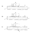
本願発明のセンサ付き真空断熱パネル1の実施形態の一例を図面に基づいて説明する。図1(a)~(d)に示すセンサ付き真空断熱パネル1は、断熱性のある板状の心材2の外周を外被材3で被覆し、基板11に取付けた真空センサ4、温度センサ、湿度センサ、加速度センサ等の各種センサ5と、データロガー(記憶部)6と、通信部(送受信部)7と、バッテリ8と、アンテナ9を外被材3の内側に設け、外被材3の内側を真空引きして(減圧して)真空状態にしたものである。真空センサ4、各種センサ5、データロガー6、通信部7、バッテリ8、アンテナ9には既存のものでも新規に開発されるものでも使用可能である。基板11にはフレキシブルフィルムの単一基板又はフレキシブルフィルムを多数枚積層した積層基板、ガラスエポキシ製、ベークライト製等のの硬質基板を使用することができる。以下の説明では、各種センサ5として温度センサを用いた場合を一例として説明する。
本願発明のセンサ付き真空断熱パネル1の実施形態の一例を図面に基づいて説明する。図1(a)~(d)に示すセンサ付き真空断熱パネル1は、断熱性のある板状の心材2の外周を外被材3で被覆し、基板11に取付けた真空センサ4、温度センサ、湿度センサ、加速度センサ等の各種センサ5と、データロガー(記憶部)6と、通信部(送受信部)7と、バッテリ8と、アンテナ9を外被材3の内側に設け、外被材3の内側を真空引きして(減圧して)真空状態にしたものである。真空センサ4、各種センサ5、データロガー6、通信部7、バッテリ8、アンテナ9には既存のものでも新規に開発されるものでも使用可能である。基板11にはフレキシブルフィルムの単一基板又はフレキシブルフィルムを多数枚積層した積層基板、ガラスエポキシ製、ベークライト製等のの硬質基板を使用することができる。以下の説明では、各種センサ5として温度センサを用いた場合を一例として説明する。
(心材)
本願発明において、心材2には発泡スチロールやFRP等を使用することもできるが、真空度の高い真空断熱材を得るためには、空気を排出し易い断熱材を使用するのが望ましい。その材質としては内部に多くの空隙や孔等(以下「空隙」という。)をもつ多孔質のものが適し、例えば、ウレタンや粉末シリカ、グラスウールを素材とするもの、セラミックファイバー、ロックウールなどの繊維材からなるものなどが挙げられる。スタイロホームも利用できるが割れやすいという難点があるので使用状況によっては注意を要する。ガラスウールは割れ難いという特性が有る。断熱材の材質、形状、サイズ、厚さ等はセンサ付き真空断熱パネル1の用途に合わせて設計される。
本願発明において、心材2には発泡スチロールやFRP等を使用することもできるが、真空度の高い真空断熱材を得るためには、空気を排出し易い断熱材を使用するのが望ましい。その材質としては内部に多くの空隙や孔等(以下「空隙」という。)をもつ多孔質のものが適し、例えば、ウレタンや粉末シリカ、グラスウールを素材とするもの、セラミックファイバー、ロックウールなどの繊維材からなるものなどが挙げられる。スタイロホームも利用できるが割れやすいという難点があるので使用状況によっては注意を要する。ガラスウールは割れ難いという特性が有る。断熱材の材質、形状、サイズ、厚さ等はセンサ付き真空断熱パネル1の用途に合わせて設計される。
(外被材)
外被材3には、フィルム状、シート状、板状のものを使用することができる。外被材3はその内部を真空状態に保つためにガスバリア性に富む材料とする。ガスバリア性に富む材料としてはステンレススチール、アルミニウム、鉄といった金属、プラスチック(樹脂)等の単一材、金属箔とプラスチックフィルムとをラミネートした複合材、プラスチックに金属を蒸着した複合材、金属シートと樹脂シートを貼り合わせた積層構造の複合材、樹脂繊維製或いは天然繊維製の織布や不織布等の布とガスバリア性のある樹脂製、金属箔製等のフィルムやシート等とを積層した複合材等を使用できる。これら外被材3の材質、厚さ、形状、サイズ、複合構造、強度等はセンサ付き真空断熱パネル1の用途に合わせて設計される。
外被材3には、フィルム状、シート状、板状のものを使用することができる。外被材3はその内部を真空状態に保つためにガスバリア性に富む材料とする。ガスバリア性に富む材料としてはステンレススチール、アルミニウム、鉄といった金属、プラスチック(樹脂)等の単一材、金属箔とプラスチックフィルムとをラミネートした複合材、プラスチックに金属を蒸着した複合材、金属シートと樹脂シートを貼り合わせた積層構造の複合材、樹脂繊維製或いは天然繊維製の織布や不織布等の布とガスバリア性のある樹脂製、金属箔製等のフィルムやシート等とを積層した複合材等を使用できる。これら外被材3の材質、厚さ、形状、サイズ、複合構造、強度等はセンサ付き真空断熱パネル1の用途に合わせて設計される。
外被材3はフィルム状、シート状のものを単独で使用し、それら外被材3で図1(a)~(c)のように心材2の外周を被覆することも、心材2の片面をフィルム状の外被材3で被覆し反対側面をシート状の外被材3で被覆することもできる。図1(d)のように心材2の片面(図1(d)では下面)に金属板、樹脂板等のガスバリア性のある板状の外被材3を配置し、心材2の他の片面及び外周面(図1(d)では上面及び側面)にフィルム状の外被材3を被せて心材2の外周を被覆することもできる。場合によっては心材2の両面に図1(d)に示すような板状の外被材3を配置し、板状の両外被材3の外側をシート状或いはフィルム状の外被材3で被覆することもできる。いずれの場合も外被材3の内側を真空引きして真空状態にする。
外被材3は材質、構造が同じもの或いは異なるもの(いずれもガスバリア性のあるもの)を二重にしたものであってもよい。二重に被覆することにより、いずれか一方の外被材3が損傷しても他方の外被材3でその内側の真空状態は確保される。
アルミニウムをはじめとする金属材を用いた外被材3は、熱伝導性が高いという特性がある半面、シールド特性(電波遮蔽性)もある。熱伝導性が高いと外被材3の内側に設けた温度センサでの温度検知には適するが、シールド特性が良いと各種センサで検知したデータを通信部7により外部と通信したり、外部機器で読み取ったりするのには適さないので、外被材3のうち通信部7やアンテナ9の外側部分は、ガスバリア性はあるがシールド特性のない電波透過性の材質とするのが望ましい。
外被材3には樹脂製のものを用いることもできる。樹脂はガスバリア性があるだけでなく、電波シールド性がないため通信面やデータの読み取り面では適するが、熱伝導性が低いため外被材3内に設けた温度センサ5での周辺温度の計測には適さない。これら全ての特性を生かすためには、金属製と樹脂製の外被材3を組み合わせて使用することもできる。一例として、外被材3のうち、温度センサ5を覆う範囲には熱伝導性の高い金属、例えばアルミニウムを使用し、通信部7を覆う範囲には電波シールド性のない樹脂を用いるのが望ましい。
外被材3はその内部(心材2内を含む)を真空引きして真空状態にしてから、真空引きした開口部をシール(例えば、ヒートシール)すると真空状態に維持することができるので、外被材3は熱溶着可能な材料と組み合わせると熱溶着し易い。例えば、アルミウムをはじめとする金属製の板、フィルム、シート等にPET(Polyethylene Terephthalate)を貼り合わせたり蒸着したりして組み合わせたものが適する。PET素材は90℃程度で熱溶着され、各種センサは通常200℃程度までは溶けることがないのでセンサにとっては好適である。
心材2や外被材3は、前記したものに限らず、従来から真空断熱材として用いられている他の材質の材料を使用することができ、特にサイズを大きめにし、更に折り曲げ可能な材質、厚さに設計すると、一枚のセンサ付き真空断熱パネル1を折り曲げて、容器本体21と蓋22を備えた断熱容器20を製作することができる。
(断熱性能)
センサ付き真空断熱パネル1は、外被材3の内部を真空状態とすることで優れた断熱性能を有する。一例としてはセンサ付き真空断熱パネル1の熱伝導率は0.002~0.01w/mkであり、発泡スチロールの0.02~0.03w/mk、空気の0.02w/mkに比べると、その断熱性能が顕著であることがわかる。
センサ付き真空断熱パネル1は、外被材3の内部を真空状態とすることで優れた断熱性能を有する。一例としてはセンサ付き真空断熱パネル1の熱伝導率は0.002~0.01w/mkであり、発泡スチロールの0.02~0.03w/mk、空気の0.02w/mkに比べると、その断熱性能が顕著であることがわかる。
(真空センサ)
真空センサ4にはピラニ真空計、隔膜真空計、静電容量型真空センサ、マイクロメカニカル真空センサ等々各種のものがある。本願発明のセンサ付き真空断熱パネル1で使用できる真空センサ4は外被材3の内側の真空状態を検知できるものであれば各種真空センサを使用可能である。真空センサ4は心材2内又は外被材3内に収容するためにはできるだけ小型、薄型のものが望ましい。真空状態は減圧状態を意味するので、例えば圧力センサを使用することができる。
真空センサ4にはピラニ真空計、隔膜真空計、静電容量型真空センサ、マイクロメカニカル真空センサ等々各種のものがある。本願発明のセンサ付き真空断熱パネル1で使用できる真空センサ4は外被材3の内側の真空状態を検知できるものであれば各種真空センサを使用可能である。真空センサ4は心材2内又は外被材3内に収容するためにはできるだけ小型、薄型のものが望ましい。真空状態は減圧状態を意味するので、例えば圧力センサを使用することができる。
(真空状態の判別)
図3ではバッテリBから供給される電源で真空センサ4を作動させ、真空センサ4で外被材3の内側の圧力を検知し、検知した電流(電圧)を増幅器Aで増幅し、増幅器Aの出力電圧を、比較器Cにおいて本願発明のセンサ付き真空断熱パネル1が必要とする適正な真空状態(外被材3内の適正圧力:基準圧力)Paと比較することにより、外被材3の内部が適正な真空状態に維持されているか否かを判別することができる。図3では検知した圧力をデジタルメータMに表示して、外被材3の内部の真空状態を確認できるようにしてある。比較器Cの出力が前記基準圧力Paよりも高い場合は、リレーRにより真空ポンプPの電磁弁を開いて、真空ポンプPで外被材3内を減圧することもできる。真空センサ4は全部を外被材3内に設けてもよいが、部分的に外被材3の外部に突出して取付けてもよい。いずれの場合も外被材3内の真空状態が損なわれないように取付ける。図3のバッテリBは外被材3の外にあるが、バッテリBは図1(a)に示すセンサ付き真空断熱パネル1内のバッテリ8を使用して、常時、センサ付き真空断熱パネル1内の真空度を検知することもできる。
図3ではバッテリBから供給される電源で真空センサ4を作動させ、真空センサ4で外被材3の内側の圧力を検知し、検知した電流(電圧)を増幅器Aで増幅し、増幅器Aの出力電圧を、比較器Cにおいて本願発明のセンサ付き真空断熱パネル1が必要とする適正な真空状態(外被材3内の適正圧力:基準圧力)Paと比較することにより、外被材3の内部が適正な真空状態に維持されているか否かを判別することができる。図3では検知した圧力をデジタルメータMに表示して、外被材3の内部の真空状態を確認できるようにしてある。比較器Cの出力が前記基準圧力Paよりも高い場合は、リレーRにより真空ポンプPの電磁弁を開いて、真空ポンプPで外被材3内を減圧することもできる。真空センサ4は全部を外被材3内に設けてもよいが、部分的に外被材3の外部に突出して取付けてもよい。いずれの場合も外被材3内の真空状態が損なわれないように取付ける。図3のバッテリBは外被材3の外にあるが、バッテリBは図1(a)に示すセンサ付き真空断熱パネル1内のバッテリ8を使用して、常時、センサ付き真空断熱パネル1内の真空度を検知することもできる。
(真空状態の管理)
真空センサ4で検知した真空データは外被材3の内側の通信部7から外部の管理センタと無線通信し、管理センタでデータ処理して真空状態の異常を確認し、センサ付き真空断熱パネル1の真空状態を管理することができる。前記通信は有線で行うこともできる。無線式の場合は図1(a)に示すアンテナ9を使用することができる。有線式の場合は、外被材3の外に外部機器と電気的に接続可能なコネクタとか他の接続機器(接続具)を設けておき、それに接続された外部機器との間で有線通信することができる。
真空センサ4で検知した真空データは外被材3の内側の通信部7から外部の管理センタと無線通信し、管理センタでデータ処理して真空状態の異常を確認し、センサ付き真空断熱パネル1の真空状態を管理することができる。前記通信は有線で行うこともできる。無線式の場合は図1(a)に示すアンテナ9を使用することができる。有線式の場合は、外被材3の外に外部機器と電気的に接続可能なコネクタとか他の接続機器(接続具)を設けておき、それに接続された外部機器との間で有線通信することができる。
(各種センサ)
本願発明で使用する前記した各種センサ5は、専用のものとして別途作成してもよいが、市販されているものを使用することもできる。
本願発明で使用する前記した各種センサ5は、専用のものとして別途作成してもよいが、市販されているものを使用することもできる。
温度センサ5は、少なくともセンサ付き真空断熱パネル1の外部の周辺温度を検知できるものであり、必要であればセンサ付き真空断熱パネル1内の温度も検知できるものである。
加速度センサはセンサ付き真空断熱パネル1の振動を検知するものであり、センサ付き真空断熱パネル1を例えば断熱容器20に使用し、その断熱容器20内に要保冷品Fを収容して自動車等で搬送する際に、断熱容器20内の要保冷品Fの振動状況を把握して要保冷品Fの品質管理に利用することができる。
湿度センサは外被材3のガスバリア性が劣化又は破損することにより外部から外被材3内に湿気が侵入した場合に、その湿気を検知することができる。この湿度を検知することにより外被材3の真空状態を管理することもできる。
(通信部)
外被材3の内側に設ける通信部7は、外部の管理センタとか他の外部機器との間で、センサが検知した各種データを随時、又はリアルタイムに送受信(通信)できるものでも、データロガー6に記憶されているデータを随時に送受信(通信)できるものでもよく、汎用の小型送受信器を使用することができる。データロガー6が各種センサの検知データを記憶でき、そのデータをパソコン等で読み取りできるものであれば、データロガー6を通信部7として使用することもでき、その場合は、専用の通信部7は不要となる。
外被材3の内側に設ける通信部7は、外部の管理センタとか他の外部機器との間で、センサが検知した各種データを随時、又はリアルタイムに送受信(通信)できるものでも、データロガー6に記憶されているデータを随時に送受信(通信)できるものでもよく、汎用の小型送受信器を使用することができる。データロガー6が各種センサの検知データを記憶でき、そのデータをパソコン等で読み取りできるものであれば、データロガー6を通信部7として使用することもでき、その場合は、専用の通信部7は不要となる。
(データロガー)
本願発明のデータロガー6には専用に開発したもの或いは汎用のデータロガーを使用することができる。汎用のデータロガーには温度データロガー、湿度データロガー、温・湿度データロガー、振動データロガー、GPS(グローバル・ポジショニング・システム)データロガー等がある。データロガー6は他のセンサで検知したデータを記憶できるだけでなく、自らが温度や湿度を検知し、その検知データを記憶できるもの、他のセンサで検知したデータを記憶できるもの等がある。また、一つで二以上のデータ、例えば温度と湿度を検知して、それらデータを記憶できるものもある。釦電池型が内蔵された温度データロガーもある。本願発明ではこれらのいずれのデータロガーでも使用可能である。データ検知と記憶の双方ができるものを使用すれば、検知用のセンサは不要であり、バッテリ内蔵型のものを使用すれば、データロガー用のバッテリを別途設ける必要もない。
本願発明のデータロガー6には専用に開発したもの或いは汎用のデータロガーを使用することができる。汎用のデータロガーには温度データロガー、湿度データロガー、温・湿度データロガー、振動データロガー、GPS(グローバル・ポジショニング・システム)データロガー等がある。データロガー6は他のセンサで検知したデータを記憶できるだけでなく、自らが温度や湿度を検知し、その検知データを記憶できるもの、他のセンサで検知したデータを記憶できるもの等がある。また、一つで二以上のデータ、例えば温度と湿度を検知して、それらデータを記憶できるものもある。釦電池型が内蔵された温度データロガーもある。本願発明ではこれらのいずれのデータロガーでも使用可能である。データ検知と記憶の双方ができるものを使用すれば、検知用のセンサは不要であり、バッテリ内蔵型のものを使用すれば、データロガー用のバッテリを別途設ける必要もない。
本願発明では真空センサ4で検知した真空データ(例えば、圧力データ)、温度センサ5で検知した温度データを、外被材3の内側に設けたデータロガー6に記憶させておき、記憶されたデータを例えば通信部7により外部の管理センタに送信するとか、読み取り機(リーダー)で読み取るとかパソコンンで読み取る(回収する)等して、真空状態や温度等を確認して、センサ付き真空断熱パネル1を使用した断熱容器20内の要保冷品Fの保冷状況を管理することもできる。
(バッテリ)
本願発明では、真空センサ4、温度センサ、湿度センサ等の各種センサ5、データロガー6、通信部7等を作動させる電源としてバッテリ8を設けてある。バッテリ8にはリチウム電池とか他の長寿命の電池を使用することができる。電池は充電式のものでも非充電式のものでも使用可能である。充電式の場合は外被材3の外に充電用電源接続器(例えば、コンセント)を設けておき、それに電源を接続することにより充電することができる。近年は、非接触式の充電、例えば、電磁波を充電に利用する充電方法も研究され、実用化の目途が立っているので、非接触式で充電が可能な電池を使用することもできる。
本願発明では、真空センサ4、温度センサ、湿度センサ等の各種センサ5、データロガー6、通信部7等を作動させる電源としてバッテリ8を設けてある。バッテリ8にはリチウム電池とか他の長寿命の電池を使用することができる。電池は充電式のものでも非充電式のものでも使用可能である。充電式の場合は外被材3の外に充電用電源接続器(例えば、コンセント)を設けておき、それに電源を接続することにより充電することができる。近年は、非接触式の充電、例えば、電磁波を充電に利用する充電方法も研究され、実用化の目途が立っているので、非接触式で充電が可能な電池を使用することもできる。
リチウム電池をはじめとする各種電池は一般に低温環境や高湿環境では劣化が進み易く極端に寿命が短くなることが知られているが、本願発明は電池を断熱性のある心材2や外被材3の内側に設けることにより低温環境や高湿環境から隔離することができる。
(ユニット)
本願発明で使用する真空センサ4、温度センサ5、データロガー6、湿度センサ、加速度センサ、通信部7、バッテリ8等は個別に心材2や外被材3の内部に設けることもできるが、一つにまとめてユニット化すると心材2や外被材3の内部に収容し易い。
本願発明で使用する真空センサ4、温度センサ5、データロガー6、湿度センサ、加速度センサ、通信部7、バッテリ8等は個別に心材2や外被材3の内部に設けることもできるが、一つにまとめてユニット化すると心材2や外被材3の内部に収容し易い。
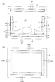
図4(a)、(b)はユニット10の一例であり、電気配線やアンテナ9が表示された基板11の片面に真空センサ4、温度センサ5、データロガー6、通信部7を搭載し、基板11の反対側面にバッテリホルダ14を設け、そのバッテリホルダ14に釦型のバッテリ8を収容してある。この基板11は硬質基板である。
図4(c)はユニット10の他例であり、フレキシブルフィルム基板11の先端側(図4(c)の上側)に温度センサ5を設け、フレキシブルフィルム基板11の他端側に通信部7を設け、その先にアンテナ9を設け、フレキシブルフィルム基板11の中央部に釦型のバッテリ8を設けてある。近年、温度センサ5、通信部7、アンテナ9等の通信用の部品は小型化が進んでいる。本願発明のセンサ付真空断熱パネル1に用いられるセンサも小型の方が望ましい。本願発明ではユニット化する部品の組み合わせは適宜選択することができ、前記部品の組み合わせ以外の組み合わせとすることもできる。
(センサ付真空断熱パネルの例)
本願発明のセンサ付き真空断熱パネル1における外被材3内へのユニット10の配置位置、配置構造は種々考えられる。その主な例を図1(a)~(d)に示す。
本願発明のセンサ付き真空断熱パネル1における外被材3内へのユニット10の配置位置、配置構造は種々考えられる。その主な例を図1(a)~(d)に示す。
図1(a)は、基板11の上面に真空センサ4、温度センサ5、データロガー6、通信部7を設け、基板11の下面にバッテリ8を設けたユニット10を、心材2に設けた凹部15内に収容固定した場合である。この場合、心材2に設けた凹部15にユニット10を収容し、その後に心材2の外周を外被材3で被覆し、外被材3の内部を真空引きして所定の真空度(基準圧力)にしてある。ユニット10を収容した凹部15内の空間には外被材3を被せる前に熱伝導性の高い充填剤を注入しておくことも、そのまま空隙として残しておくこともできる。バッテリ8は心材2の肉厚方向略中心部に配置して、外部の低温・高湿度環境の影響を受けにくくしてある。
図1(b)は基板11の下面に真空センサ4、データロガー6、通信部7、バッテリ8を設け、上面に温度センサ5を設けたユニット10を、温度センサ5を上向きにして心材2の上に配置し、真空センサ4、データロガー6、通信部7、バッテリ8を心材2内に配置したものである。このように配置することにより、温度センサ5で外部温度を検知し易くし、真空センサ4、データロガー6、通信部7、バッテリ8を破損しにくくしてある。この場合はユニット10が外被材3のみで覆われているので、温度計測や通信という点で好適である。また、バッテリ8は心材2内に配置されているので、外部の低温・高湿環境から守られる。
図1(c)は、基板11を上にして真空センサ4、データロガー6、通信部7、バッテリ8を心材2内に配置し、基板11を心材2に設けた貫通孔や貫通溝の中を通して心材2の肉厚方向反対側(図1(c)の下側)に導出し、その導出部に取付けてある温度センサ5を心材2の裏面側に配置したものである。
図1(d)は、基板11とその上に配置した真空センサ4、温度センサ5、データロガー6、通信部7、バッテリ8を心材2内に設けた凹部15に収容し、心材2の裏面に板状の外被材3を配置し、その心材2の上面から側面に樹脂シートの外被材3を被せ、その外被材3を前記板状の外被材3に密着させて心材2を被覆し、板状の外被材3とシート状の外被材3の内側を真空状態にしたものである。板状の外被材3は金属板とか樹脂板とすることができる。
本願発明のセンサ付き真空断熱パネル1は、図1(d)の心材2の上に被せたシート状の外被材3を板状の外被材3に代えて、心材2を上下から板状の外被材3で挟み、両外被材3の間をシート状の外被材3で密封してから、その内側を真空状態にすることもできる。
図2(a)は、基板11の上に温度センサ5とバッテリ8と通信部7とを搭載したユニット10を心材2の上に配置固定し、ユニット10の外から外被材3で心材2を被覆し、外被材3の内側を真空状態にしたものである。この場合、温度センサ5、通信部7、アンテナ9は外被材3のみで覆われているので、温度検知や通信という点では好適である。
図2(b)は、ユニット10のうち基板11、温度センサ5、通信部7、アンテナ9を心材2の表面に配置し、バッテリ8を心材2内に配置し、外被材3の内側を真空状態にしてある。
図2(c)は、ユニット10の通信部7とアンテナ9とバッテリ8を心材2の上面に配置し、基板11を心材2の裏面(下面)に通じるように心材2に設けた貫通孔や溝に沿って心材2の裏面に引き出し、基板11の先端に設けた温度センサ5を心材2の裏面に配置し、外被材3の内側を真空状態にしてある。
(センサ付き真空断熱パネルの製造方法)
本願発明のセンサ付き真空断熱パネル1は、心材2の外周を外被材3で被覆した状態で、外被材3の内部を真空ポンプ等で減圧し、外被材3の開口部を密封して、外被材3の内部を真空状態に保持する。密封は熱溶着(ヒートシール)、接着剤による密着等、各種方法で行うことができる。心材2として使用する断熱材には、内部に多くの空隙があり、吸引機による抜気等により空隙内の空気を排出することができるものもある。このような断熱材は外被材3の内部を真空装置で減圧して真空状態にすることにより断熱材の内部も減圧される。断熱材が湿気を帯びているとその後の真空状態が保持され難いので、外被材3内の抜空作業(減圧作業)は乾燥空気を送りながら行うなど乾燥環境下で実施するのが望ましい。前記真空状態とは、必ずしも絶対真空状態に限らず、真空度の高い状態を指すもので、1~200Pa、望ましくは1~100Pa程度の真空度となる状態を意味する。
本願発明のセンサ付き真空断熱パネル1は、心材2の外周を外被材3で被覆した状態で、外被材3の内部を真空ポンプ等で減圧し、外被材3の開口部を密封して、外被材3の内部を真空状態に保持する。密封は熱溶着(ヒートシール)、接着剤による密着等、各種方法で行うことができる。心材2として使用する断熱材には、内部に多くの空隙があり、吸引機による抜気等により空隙内の空気を排出することができるものもある。このような断熱材は外被材3の内部を真空装置で減圧して真空状態にすることにより断熱材の内部も減圧される。断熱材が湿気を帯びているとその後の真空状態が保持され難いので、外被材3内の抜空作業(減圧作業)は乾燥空気を送りながら行うなど乾燥環境下で実施するのが望ましい。前記真空状態とは、必ずしも絶対真空状態に限らず、真空度の高い状態を指すもので、1~200Pa、望ましくは1~100Pa程度の真空度となる状態を意味する。
(断熱容器)
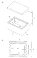
本願発明の断熱容器20の実施形態の一例を図に基づいて説明する。図5(a)、(b)の断熱容器20は保冷を必要とする要保冷品Fを収容して搬送できるものであり、容器本体21と蓋22を備えている。容器本体21及び蓋22は新規に作成することもできるが、現在利用されている保冷容器をそのまま利用することもできる。既存の保冷容器の容器本体21及び蓋22は断熱材製であり、代表的なものとしては発泡スチロール製である。
本願発明の断熱容器20の実施形態の一例を図に基づいて説明する。図5(a)、(b)の断熱容器20は保冷を必要とする要保冷品Fを収容して搬送できるものであり、容器本体21と蓋22を備えている。容器本体21及び蓋22は新規に作成することもできるが、現在利用されている保冷容器をそのまま利用することもできる。既存の保冷容器の容器本体21及び蓋22は断熱材製であり、代表的なものとしては発泡スチロール製である。
図5(a)、(b)の蓋22は、容器本体21の上から被せて嵌合できるものであり、容器本体21に被せると容器本体21内の収容空間23が略密閉されて、収容空間23内に収められた要保冷品F(図6)を外部の熱から遮断する(断熱する)ことができる。
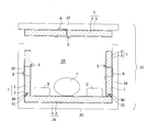
図6に示すように、容器本体21の四周(四枚)の周壁24の内側と、蓋22の内側には本願発明のセンサ付き真空断熱パネル1が配置され、底25の内面にはセンサを備えない真空断熱パネル(センサ無し真空断熱パネル)26が配置されている。これらセンサ付き真空断熱パネル1、センサ無し真空断熱パネル26は各壁の内面に固定することも、固定せずに配置するだけとすることもできる。
図6では温度センサ5を収容空間23側にし、バッテリ8を外側にして配置して、温度センサ5での温度検知に好適であり、バッテリ8が低温・高湿の収容空間23から離れて品質劣化が抑制されるようにしてある。
図6のようにセンサ付き真空断熱パネル1、センサ無し真空断熱パネル26を配置することによって、収容空間23内を外部から断熱し、センサ付き真空断熱パネル1の温度センサ5で検知した温度データを利用して収容空間23内の温度を管理することができる。この場合も、真空センサ4によって外被材3の内側の真空状態を検知してセンサ付き真空断熱パネル1の真空状態を監視し、真空管理することができる。センサ付真空断熱パネル1の内部に設置されたバッテリ8は収容空間23から断熱されているため低温環境・高湿環境による劣化(短寿命化)の問題を解消できる。また、各種センサ5で得られた温度データ、真空データ、湿度データ、加速度データ等の各種データを通信部7によって外部に送信できるので、収容空間23内の温度、湿度等をはじめとして、断熱容器20の移動時の状態を監視して、断熱容器20内の要保冷品Fを品質管理することができる。
図6では周壁24の内面に設けたセンサ付き真空断熱パネル1の嵌合凹部30と、底25に設けたセンサ無し真空断熱パネル26の嵌合凸部31を嵌合させてあるが、両真空断熱パネル1、26は必ずしも嵌合させる必要はなく、単に突き合わせるだけでもよい。
本願発明の断熱容器20は図7(a)、(b)に示すように、新規に作成される容器本体21及び蓋22の内面側に、センサ付真空断熱パネル1又はセンサ無し真空断熱パネル26を作成時に埋め込んでおく(内蔵しておく)こともできる。この場合、どの部材にセンサ付真空断熱パネル1を内蔵させて、どの部材にセンサ無し真空断熱パネル26を内蔵させるかは任意に設計することができる。
本願発明の断熱容器20は図8に示すように、蓋22を蓋本体22aとそれに密閉状態に脱着可能なカバー22bで構成し、蓋本体22a内に蓋空間27を設け、蓋空間27内にドライアイスD等を収容し、蓋本体22aの内面にセンサ付き真空断熱パネル1を貼り付けてある。蓋本体22aの内面にはセンサ無し真空断熱パネル26を貼り付けることもできる。
本願発明の断熱容器20は図6のような断熱材製の容器を使用せず、図9のように、外側の外被材3が厚板である図1(d)のセンサ付き真空断熱パネル1だけで構成することもできる。図9では図1(d)に示すセンサ付き真空断熱パネル1を底25、周壁24、蓋22に使用し、肉厚板状の外被材3を外側にして配置してある。この場合、板状の外被材3を内側にして配置することもできる。この場合、底25、周壁24、蓋22の全てを図1(d)のセンサ付真空断熱パネル1とすることもできるし、一部のみをセンサ付真空断熱パネル1として他をセンサ無し真空断熱パネル26とすることも可能であり、その配置、組合せは任意に設計できる。
本願発明のセンサ付き真空断熱パネル1は、家屋の床材や外壁材といった建材としても利用することができる。本願発明の断熱容器20は食品類の宅配用のほか化粧品、薬品、電子部品、精密機器、臓器等々のあらゆる要保冷品Fの搬送用としても応用することができる。
1:センサ付き真空断熱パネル、2:心材、3:外被材、
4:真空センサ、5:各種センサ(温度センサ)、6:データロガー(記憶部)、
7:通信部(送受信部)、8:バッテリ、9:アンテナ、10:ユニット、
11:基板、14:バッテリホルダ、15:凹部、20:断熱容器、
21:容器本体、22:蓋、22a:蓋本体、22b:カバー、
23:収容空間、24:周壁、25:底、26:センサ無し真空断熱パネル、
27:蓋空間、30:嵌合凹部、31:嵌合凸部、
A:増幅器、B:バッテリ、C:比較器、D:ドライアイス、F:要保冷品、
M:デジタルメータ、P:真空ポンプ、Pa:基準圧力(基準値)、R:リレー
4:真空センサ、5:各種センサ(温度センサ)、6:データロガー(記憶部)、
7:通信部(送受信部)、8:バッテリ、9:アンテナ、10:ユニット、
11:基板、14:バッテリホルダ、15:凹部、20:断熱容器、
21:容器本体、22:蓋、22a:蓋本体、22b:カバー、
23:収容空間、24:周壁、25:底、26:センサ無し真空断熱パネル、
27:蓋空間、30:嵌合凹部、31:嵌合凸部、
A:増幅器、B:バッテリ、C:比較器、D:ドライアイス、F:要保冷品、
M:デジタルメータ、P:真空ポンプ、Pa:基準圧力(基準値)、R:リレー
Claims (11)
- 断熱性のある心材がガスバリア性の外被材で被覆され、外被材の内側が真空状態である真空断熱パネルにおいて、バッテリと、少なくとも外被材の外側温度を検知可能な温度センサと、温度センサによる検知データを無線又は有線で外部と通信可能な通信部と検知データを記憶できるデータロガーの双方又はいずれか一方が、個別に又はユニット化されて前記外被材の内側に設置されたことを特徴とするセンサ付真空断熱パネル。
- 請求項1記載のセンサ付真空断熱パネルにおいて、温度センサの他に、真空センサ、加速度センサ、湿度センサのいずれか一又は二以上のセンサをも設け、これらセンサは個別に、又は温度センサ、バッテリ、データロガーのいずれか一又は二以上とユニット化して外被材の内側に設置し、データロガーは前記温度センサ、真空センサ、加速度センサ、湿度センサの一以上のセンサの検知データをも記憶できることを特徴とするセンサ付真空断熱パネル。
- 請求項1又は請求項2記載のセンサ付真空断熱パネルにおいて、データロガーに記憶された検知データは、通信部により外部と通信することも、外部機器で読み取ることもできることを特徴とするセンサ付真空断熱パネル。
- 請求項1ないし請求項3のいずれか1項記載のセンサ付真空断熱パネルにおいて、外被材の内側に設けられる温度センサ、通信部、データロガー、バッテリ、真空センサ、加速度センサ、湿度センサのうち一又は二以上を、心材の一部に設けられた凹部内又は心材の表面に設けたことを特徴とするセンサ付真空断熱パネル。
- 請求項1ないし請求項4のいずれか1項記載のセンサ付真空断熱パネルにおいて、外被材が熱伝導性素材と電波透過性素材を組み合わせて形成され、外被材のうち通信部を覆う範囲が電波透過性素材であり、温度センサを覆う範囲が熱伝導性素材であることを特徴とするセンサ付真空断熱パネル。
- 請求項1ないし請求項5のいずれか1項記載のセンサ付真空断熱パネルにおいて、通信部又はデータロガーと有線で接続可能な接続具が、外被材の外側に設けられたことを特徴とするセンサ付真空断熱パネル。
- 請求項1ないし請求項6のいずれか1項記載のセンサ付真空断熱パネルにおいて、バッテリが充電式であり、バッテリに充電電源を接続可能な充電端子が、外被材の外側に設けられたことを特徴とするセンサ付真空断熱パネル。
- 請求項1ないし請求項7のいずれか1項記載のセンサ付真空断熱パネルにおいて、バッテリが非接触の充電式であることを特徴とするセンサ付真空断熱パネル。
- 底と周壁を有する容器本体と蓋を備えた断熱容器において、底と周壁と蓋のいずれか一又は二以上の内側又は外側に、請求項1ないし請求項8のいずれか1項記載のセンサ付き真空断熱パネルが配置されたことを特徴とする真空断熱容器。
- 底と周壁を有する容器本体と蓋を備えた断熱容器において、底と周壁と蓋のいずれか一又は二以上が、請求項1ないし乃至請求項8のいずれか1項記載のセンサ付き真空断熱パネルで形成されたことを特徴とする断熱容器。
- 請求項10記載の断熱容器において、センサ付き真空断熱パネルの外被材が硬質材製の板状であり、板状の外被材が底、周壁、蓋の外側に配置されたことを特徴とする断熱容器。
Applications Claiming Priority (6)
| Application Number | Priority Date | Filing Date | Title |
|---|---|---|---|
| JP2010173919A JP4641565B1 (ja) | 2010-08-02 | 2010-08-02 | センサ付真空断熱パネル |
| JP2010-173919 | 2010-08-02 | ||
| JP2010-289737 | 2010-12-27 | ||
| JP2010289737A JP2012136254A (ja) | 2010-12-27 | 2010-12-27 | センサ付き真空断熱パネルとそれを利用した断熱容器 |
| JP2011-034444 | 2011-02-21 | ||
| JP2011034444A JP2012051647A (ja) | 2010-08-02 | 2011-02-21 | 保冷容器とセンサ付真空断熱パネル |
Publications (1)
| Publication Number | Publication Date |
|---|---|
| WO2012017903A1 true WO2012017903A1 (ja) | 2012-02-09 |
Family
ID=45559404
Family Applications (1)
| Application Number | Title | Priority Date | Filing Date |
|---|---|---|---|
| PCT/JP2011/067199 Ceased WO2012017903A1 (ja) | 2010-08-02 | 2011-07-28 | センサ付き真空断熱パネルとそのパネルを利用した断熱容器 |
Country Status (1)
| Country | Link |
|---|---|
| WO (1) | WO2012017903A1 (ja) |
Cited By (18)
| Publication number | Priority date | Publication date | Assignee | Title |
|---|---|---|---|---|
| JP2014062645A (ja) * | 2012-08-31 | 2014-04-10 | Nichias Corp | 断熱ユニット、断熱ユニットの製造方法および加熱炉 |
| JP2016017635A (ja) * | 2014-07-03 | 2016-02-01 | ケーニヒ メタル ゲゼルシャフト ミット ベシュレンクテル ハフツング ウント コンパニー コマンディートゲゼルシャフトKoenig Metall GmbH & Co. KG | 絶縁ハウジング及び該絶縁ハウジングを製造する方法 |
| WO2016074658A1 (de) * | 2014-11-13 | 2016-05-19 | Fkn-Fassaden Gmbh+Co.Kg | Fassadensystem zur renovierung von altbauten mit feuerfesten fassadenelementen hoher wärme-dämmwirkung bei unebenem untergrund der gebäudewand und verfahren zu dessen herstellung |
| JP6341588B1 (ja) * | 2017-02-28 | 2018-06-13 | 株式会社イージステクノロジーズ | 収容箱、データロギング装置、および収容箱の製造方法 |
| WO2018158323A1 (de) * | 2017-03-01 | 2018-09-07 | Va-Q-Tec Ag | Verfahren zur überprüfung der funktionstüchtigkeit der wärmeisolation eines transportbehälters |
| CN108572356A (zh) * | 2018-06-08 | 2018-09-25 | 无锡华测电子系统有限公司 | 一种低温测试盒 |
| US10676267B2 (en) | 2015-11-25 | 2020-06-09 | Yeti Coolers, Llc | Insulating container having vacuum insulated panels and method |
| USD910382S1 (en) | 2017-05-16 | 2021-02-16 | Yeti Coolers, Llc | Insulating device |
| EP3798554A1 (en) * | 2019-09-25 | 2021-03-31 | Whirlpool Corporation | Feature in vacuum insulated structure to allow pressure monitoring |
| EP3693649A4 (en) * | 2017-10-03 | 2021-05-05 | Asahi Fiber Glass Co., Ltd. | VACUUM THERMAL INSULATION MATERIAL |
| WO2021171648A1 (ja) * | 2020-02-28 | 2021-09-02 | パナソニックIpマネジメント株式会社 | 真空断熱体及びこの検査システム |
| JPWO2021205785A1 (ja) * | 2020-04-06 | 2021-10-14 | ||
| WO2023042495A1 (ja) | 2021-09-14 | 2023-03-23 | パナソニックIpマネジメント株式会社 | 保冷材の検査装置及び検査システム |
| US20230175912A1 (en) * | 2021-12-06 | 2023-06-08 | Whirlpool Corporation | Insulated structure for an appliance |
| EP4198422A1 (en) * | 2021-12-16 | 2023-06-21 | Whirlpool Corporation | Door assembly |
| CN116670046A (zh) * | 2021-03-26 | 2023-08-29 | 松下知识产权经营株式会社 | 真空隔热容器 |
| EP4184141A4 (en) * | 2020-07-17 | 2024-01-03 | Panasonic Intellectual Property Management Co., Ltd. | VACUUM HEAT INSULATOR MANAGEMENT SYSTEM |
| US12385797B2 (en) | 2023-02-17 | 2025-08-12 | Whirlpool Corporation | Pressure sensor hub for a vacuum-insulated structure |
Citations (11)
| Publication number | Priority date | Publication date | Assignee | Title |
|---|---|---|---|---|
| JPS6171895U (ja) * | 1984-10-17 | 1986-05-16 | ||
| JPH10239199A (ja) * | 1997-02-28 | 1998-09-11 | Toshiba Corp | 真空度測定装置 |
| JP2006078190A (ja) * | 2004-09-07 | 2006-03-23 | Sumitomo Electric Ind Ltd | 真空断熱構造の真空度低下の監視装置および方法 |
| JP2006118559A (ja) * | 2004-10-20 | 2006-05-11 | Matsushita Electric Ind Co Ltd | 真空断熱材、真空断熱材の断熱性能確認方法、断熱容器、並びに、断熱容器利用システム |
| JP2007022598A (ja) * | 2005-07-15 | 2007-02-01 | Sekisui Plastics Co Ltd | 温度検出器付き保温保冷容器 |
| JP2009509109A (ja) * | 2005-09-23 | 2009-03-05 | ヴァ−クー−テック アーゲー | フィルムで被覆され、粉末が充填された真空断熱材の製造方法 |
| JP2009075076A (ja) * | 2007-08-28 | 2009-04-09 | Yamari Sangyo Kk | 温度計測器の耐熱保護ボックス及びこれを用いた温度計測装置、並びに温度計測方法 |
| JP2009074848A (ja) * | 2007-09-19 | 2009-04-09 | Citizen Holdings Co Ltd | 体温測定装置 |
| JP2009222543A (ja) * | 2008-03-17 | 2009-10-01 | Citizen Holdings Co Ltd | 体温計 |
| JP2009250530A (ja) * | 2008-04-07 | 2009-10-29 | Mitsubishi Electric Corp | 貯湯式給湯器 |
| JP4641565B1 (ja) * | 2010-08-02 | 2011-03-02 | 株式会社本宏製作所 | センサ付真空断熱パネル |
-
2011
- 2011-07-28 WO PCT/JP2011/067199 patent/WO2012017903A1/ja not_active Ceased
Patent Citations (11)
| Publication number | Priority date | Publication date | Assignee | Title |
|---|---|---|---|---|
| JPS6171895U (ja) * | 1984-10-17 | 1986-05-16 | ||
| JPH10239199A (ja) * | 1997-02-28 | 1998-09-11 | Toshiba Corp | 真空度測定装置 |
| JP2006078190A (ja) * | 2004-09-07 | 2006-03-23 | Sumitomo Electric Ind Ltd | 真空断熱構造の真空度低下の監視装置および方法 |
| JP2006118559A (ja) * | 2004-10-20 | 2006-05-11 | Matsushita Electric Ind Co Ltd | 真空断熱材、真空断熱材の断熱性能確認方法、断熱容器、並びに、断熱容器利用システム |
| JP2007022598A (ja) * | 2005-07-15 | 2007-02-01 | Sekisui Plastics Co Ltd | 温度検出器付き保温保冷容器 |
| JP2009509109A (ja) * | 2005-09-23 | 2009-03-05 | ヴァ−クー−テック アーゲー | フィルムで被覆され、粉末が充填された真空断熱材の製造方法 |
| JP2009075076A (ja) * | 2007-08-28 | 2009-04-09 | Yamari Sangyo Kk | 温度計測器の耐熱保護ボックス及びこれを用いた温度計測装置、並びに温度計測方法 |
| JP2009074848A (ja) * | 2007-09-19 | 2009-04-09 | Citizen Holdings Co Ltd | 体温測定装置 |
| JP2009222543A (ja) * | 2008-03-17 | 2009-10-01 | Citizen Holdings Co Ltd | 体温計 |
| JP2009250530A (ja) * | 2008-04-07 | 2009-10-29 | Mitsubishi Electric Corp | 貯湯式給湯器 |
| JP4641565B1 (ja) * | 2010-08-02 | 2011-03-02 | 株式会社本宏製作所 | センサ付真空断熱パネル |
Cited By (41)
| Publication number | Priority date | Publication date | Assignee | Title |
|---|---|---|---|---|
| JP2014062645A (ja) * | 2012-08-31 | 2014-04-10 | Nichias Corp | 断熱ユニット、断熱ユニットの製造方法および加熱炉 |
| JP2016017635A (ja) * | 2014-07-03 | 2016-02-01 | ケーニヒ メタル ゲゼルシャフト ミット ベシュレンクテル ハフツング ウント コンパニー コマンディートゲゼルシャフトKoenig Metall GmbH & Co. KG | 絶縁ハウジング及び該絶縁ハウジングを製造する方法 |
| CN105352252A (zh) * | 2014-07-03 | 2016-02-24 | 柯尼希金属有限两合公司 | 隔绝外壳和用于制造该隔绝外壳的方法 |
| US9527653B2 (en) | 2014-07-03 | 2016-12-27 | Koenig Metall Gmbh & Co. Kg | Insulation housing and method for the production of an insulation housing |
| CN105352252B (zh) * | 2014-07-03 | 2018-05-04 | 柯尼希金属有限两合公司 | 隔绝外壳和用于制造该隔绝外壳的方法 |
| WO2016074658A1 (de) * | 2014-11-13 | 2016-05-19 | Fkn-Fassaden Gmbh+Co.Kg | Fassadensystem zur renovierung von altbauten mit feuerfesten fassadenelementen hoher wärme-dämmwirkung bei unebenem untergrund der gebäudewand und verfahren zu dessen herstellung |
| US10676267B2 (en) | 2015-11-25 | 2020-06-09 | Yeti Coolers, Llc | Insulating container having vacuum insulated panels and method |
| US12378058B2 (en) | 2015-11-25 | 2025-08-05 | Yeti Coolers, Llc | US CIP: insulating container having vacuum insulated panels and method |
| US11279546B2 (en) | 2015-11-25 | 2022-03-22 | Yeti Coolers, Llc | Insulating container having vacuum insulated panels and method |
| JP6341588B1 (ja) * | 2017-02-28 | 2018-06-13 | 株式会社イージステクノロジーズ | 収容箱、データロギング装置、および収容箱の製造方法 |
| WO2018158861A1 (ja) * | 2017-02-28 | 2018-09-07 | 株式会社イージステクノロジーズ | 収容箱、データロギング装置、および収容箱の製造方法 |
| JP2020509382A (ja) * | 2017-03-01 | 2020-03-26 | ヴァクテック アクチェンゲゼルシャフト | 輸送コンテナの断熱部の機能的能力を点検する方法 |
| WO2018158323A1 (de) * | 2017-03-01 | 2018-09-07 | Va-Q-Tec Ag | Verfahren zur überprüfung der funktionstüchtigkeit der wärmeisolation eines transportbehälters |
| USD910382S1 (en) | 2017-05-16 | 2021-02-16 | Yeti Coolers, Llc | Insulating device |
| USD1088752S1 (en) | 2017-05-16 | 2025-08-19 | Yeti Coolers, Llc | Insulating device |
| USD992359S1 (en) | 2017-05-16 | 2023-07-18 | Yeti Coolers, Llc | Insulating device |
| EP3693649A4 (en) * | 2017-10-03 | 2021-05-05 | Asahi Fiber Glass Co., Ltd. | VACUUM THERMAL INSULATION MATERIAL |
| CN108572356A (zh) * | 2018-06-08 | 2018-09-25 | 无锡华测电子系统有限公司 | 一种低温测试盒 |
| US11248979B2 (en) | 2019-09-25 | 2022-02-15 | Whirlpool Corporation | Feature in vacuum insulated structure to allow pressure monitoring |
| US11761839B2 (en) | 2019-09-25 | 2023-09-19 | Whirlpool Corporation | Feature in vacuum insulated structure to allow pressure monitoring |
| US12480830B2 (en) | 2019-09-25 | 2025-11-25 | Whirlpool Corporation | Feature in vacuum insulated structure to allow pressure monitoring |
| EP3798554A1 (en) * | 2019-09-25 | 2021-03-31 | Whirlpool Corporation | Feature in vacuum insulated structure to allow pressure monitoring |
| US12085463B2 (en) | 2020-02-28 | 2024-09-10 | Panasonic Intellectual Property Management Co., Ltd. | Vacuum insulator and system for testing the same |
| CN113677602A (zh) * | 2020-02-28 | 2021-11-19 | 松下知识产权经营株式会社 | 真空隔热体及其检查系统 |
| CN113677602B (zh) * | 2020-02-28 | 2023-07-14 | 松下知识产权经营株式会社 | 真空隔热体及其检查系统 |
| JP2021134891A (ja) * | 2020-02-28 | 2021-09-13 | パナソニックIpマネジメント株式会社 | 真空断熱体及びこの検査システム |
| JP7194899B2 (ja) | 2020-02-28 | 2022-12-23 | パナソニックIpマネジメント株式会社 | 真空断熱体及びこの検査システム |
| WO2021171648A1 (ja) * | 2020-02-28 | 2021-09-02 | パナソニックIpマネジメント株式会社 | 真空断熱体及びこの検査システム |
| EP4113088A4 (en) * | 2020-02-28 | 2023-10-11 | Panasonic Intellectual Property Management Co., Ltd. | VACUUM HEAT INSULATOR AND METHOD FOR INSPECTING THE SAME |
| JPWO2021205785A1 (ja) * | 2020-04-06 | 2021-10-14 | ||
| JP7340094B2 (ja) | 2020-04-06 | 2023-09-06 | Phcホールディングス株式会社 | 薬品収納ボックス |
| EP4184141A4 (en) * | 2020-07-17 | 2024-01-03 | Panasonic Intellectual Property Management Co., Ltd. | VACUUM HEAT INSULATOR MANAGEMENT SYSTEM |
| CN116670046A (zh) * | 2021-03-26 | 2023-08-29 | 松下知识产权经营株式会社 | 真空隔热容器 |
| US12623829B2 (en) * | 2021-03-26 | 2026-05-12 | Panasonic Intellectual Property Management Co., Ltd. | Vacuum heat insulating container |
| WO2023042495A1 (ja) | 2021-09-14 | 2023-03-23 | パナソニックIpマネジメント株式会社 | 保冷材の検査装置及び検査システム |
| US11906379B2 (en) * | 2021-12-06 | 2024-02-20 | Whirlpool Corporation | Insulated structure for an appliance |
| US12281950B2 (en) | 2021-12-06 | 2025-04-22 | Whirlpool Corporation | Insulated structure for an appliance |
| US20230175912A1 (en) * | 2021-12-06 | 2023-06-08 | Whirlpool Corporation | Insulated structure for an appliance |
| US12038340B2 (en) | 2021-12-16 | 2024-07-16 | Whirlpool Corporation | Sensor assembly for vacuum insulated structure |
| EP4198422A1 (en) * | 2021-12-16 | 2023-06-21 | Whirlpool Corporation | Door assembly |
| US12385797B2 (en) | 2023-02-17 | 2025-08-12 | Whirlpool Corporation | Pressure sensor hub for a vacuum-insulated structure |
Similar Documents
| Publication | Publication Date | Title |
|---|---|---|
| JP2012180904A (ja) | 断熱センサ類 | |
| JP2012051647A (ja) | 保冷容器とセンサ付真空断熱パネル | |
| EP3693649B1 (en) | Vacuum heat-insulating material | |
| JP2012136254A (ja) | センサ付き真空断熱パネルとそれを利用した断熱容器 | |
| US8152367B2 (en) | Insulated container having a temperature monitoring device | |
| JP2012172906A (ja) | 冷却機器付き断熱容器とその断熱容器を搭載した自動車 | |
| JP2012171733A (ja) | 物品配送システム | |
| JP6108180B2 (ja) | 真空断熱材およびこれを用いた断熱筐体 | |
| US10589919B2 (en) | Thermally insulated transport container comprising thermal insulation resting against the walls, and wall structure of a container of said type | |
| CN108368963A (zh) | 真空隔热体、具有其的隔热设备、和真空隔热体的制造方法 | |
| KR20080011272A (ko) | 비워지는 열 절연 패널 | |
| JP7394326B2 (ja) | 真空断熱容器 | |
| WO2002002433A2 (en) | Thermal container with data monitoring system | |
| JP2012180903A (ja) | 折り曲げ断熱パネルとそれを使用した断熱容器 | |
| JP4641565B1 (ja) | センサ付真空断熱パネル | |
| WO2020046385A1 (en) | A temperature stabilizing cargo compartment comprised of a plurality of layers | |
| JP7194899B2 (ja) | 真空断熱体及びこの検査システム | |
| KR20120035491A (ko) | 진공 단열재의 진공상태 모니터링 방법 및 진공 단열재 | |
| EP4184141B1 (en) | Management system for vacuum heat insulating body | |
| JP2012031987A (ja) | センサ付真空断熱パネル | |
| WO2025075184A1 (ja) | 容器及び方法 | |
| AU2023373364A1 (en) | Cooled storage system and method of its monitoring |
Legal Events
| Date | Code | Title | Description |
|---|---|---|---|
| 121 | Ep: the epo has been informed by wipo that ep was designated in this application |
Ref document number: 11814530 Country of ref document: EP Kind code of ref document: A1 |
|
| NENP | Non-entry into the national phase |
Ref country code: DE |
|
| 122 | Ep: pct application non-entry in european phase |
Ref document number: 11814530 Country of ref document: EP Kind code of ref document: A1 |