WO2012017942A1 - 電力供給システム - Google Patents
電力供給システム Download PDFInfo
- Publication number
- WO2012017942A1 WO2012017942A1 PCT/JP2011/067448 JP2011067448W WO2012017942A1 WO 2012017942 A1 WO2012017942 A1 WO 2012017942A1 JP 2011067448 W JP2011067448 W JP 2011067448W WO 2012017942 A1 WO2012017942 A1 WO 2012017942A1
- Authority
- WO
- WIPO (PCT)
- Prior art keywords
- power
- unit
- storage unit
- load
- power storage
- Prior art date
- Legal status (The legal status is an assumption and is not a legal conclusion. Google has not performed a legal analysis and makes no representation as to the accuracy of the status listed.)
- Ceased
Links
Images


Classifications
-
- H—ELECTRICITY
- H01—ELECTRIC ELEMENTS
- H01M—PROCESSES OR MEANS, e.g. BATTERIES, FOR THE DIRECT CONVERSION OF CHEMICAL ENERGY INTO ELECTRICAL ENERGY
- H01M10/00—Secondary cells; Manufacture thereof
- H01M10/42—Methods or arrangements for servicing or maintenance of secondary cells or secondary half-cells
-
- G—PHYSICS
- G01—MEASURING; TESTING
- G01R—MEASURING ELECTRIC VARIABLES; MEASURING MAGNETIC VARIABLES
- G01R31/00—Arrangements for testing electric properties; Arrangements for locating electric faults; Arrangements for electrical testing characterised by what is being tested not provided for elsewhere
- G01R31/36—Arrangements for testing, measuring or monitoring the electrical condition of accumulators or electric batteries, e.g. capacity or state of charge [SoC]
- G01R31/382—Arrangements for monitoring battery or accumulator variables, e.g. SoC
-
- H—ELECTRICITY
- H01—ELECTRIC ELEMENTS
- H01M—PROCESSES OR MEANS, e.g. BATTERIES, FOR THE DIRECT CONVERSION OF CHEMICAL ENERGY INTO ELECTRICAL ENERGY
- H01M10/00—Secondary cells; Manufacture thereof
- H01M10/42—Methods or arrangements for servicing or maintenance of secondary cells or secondary half-cells
- H01M10/44—Methods for charging or discharging
-
- H—ELECTRICITY
- H02—GENERATION; CONVERSION OR DISTRIBUTION OF ELECTRIC POWER
- H02J—ELECTRIC POWER NETWORKS; CIRCUIT ARRANGEMENTS OR SYSTEMS FOR SUPPLYING OR DISTRIBUTING ELECTRIC POWER; SYSTEMS FOR STORING ELECTRIC ENERGY
- H02J3/00—Circuit arrangements for AC mains or AC distribution networks
- H02J3/28—Arrangements for balancing of the load in networks by storage of energy
- H02J3/32—Arrangements for balancing of the load in networks by storage of energy using batteries or super capacitors with converting means
-
- Y—GENERAL TAGGING OF NEW TECHNOLOGICAL DEVELOPMENTS; GENERAL TAGGING OF CROSS-SECTIONAL TECHNOLOGIES SPANNING OVER SEVERAL SECTIONS OF THE IPC; TECHNICAL SUBJECTS COVERED BY FORMER USPC CROSS-REFERENCE ART COLLECTIONS [XRACs] AND DIGESTS
- Y02—TECHNOLOGIES OR APPLICATIONS FOR MITIGATION OR ADAPTATION AGAINST CLIMATE CHANGE
- Y02E—REDUCTION OF GREENHOUSE GAS [GHG] EMISSIONS, RELATED TO ENERGY GENERATION, TRANSMISSION OR DISTRIBUTION
- Y02E60/00—Enabling technologies; Technologies with a potential or indirect contribution to GHG emissions mitigation
- Y02E60/10—Energy storage using batteries
Definitions
- the present invention relates to a power supply system that supplies power.
- Such a storage battery can be discharged (supplied with electric power) at an arbitrary timing by being charged in advance (consuming electric power). That is, by controlling the timing of charging and discharging the storage battery, it is possible to control the timing of consuming grid power (power supplied from an electric power company; the same applies hereinafter).
- the electricity charge for grid power includes a fixed basic charge and a usage-based charge.
- the electric power company is setting so that a basic charge may become cheap, so that the maximum value of the electric energy of the system electric power consumed per unit time becomes small.
- the price per unit power of the usage fee is set to be lower at night when the power consumption can be smaller than during the daytime when the power consumption can be increased. Therefore, the system power consumer can lower the power rate as the power consumption is leveled.
- the power company can efficiently generate power (especially thermal power generation), so that it is possible to reduce carbon dioxide emissions associated with power generation.
- the leveling of power consumption is, for example, by discharging the storage battery when the amount of power consumed per unit time increases momentarily, or by charging the storage battery at night and discharging the storage battery during the day, Can be planned.
- the leveling of power consumption is, for example, by discharging the storage battery when the amount of power consumed per unit time increases momentarily, or by charging the storage battery at night and discharging the storage battery during the day, Can be planned.
- a method for grasping the remaining capacity of the storage battery for example, a method for estimating the remaining capacity based on the voltage value of the storage battery or a certain state (for example, a sufficiently charged state), and charging and discharging are performed.
- these methods are problematic because the estimation accuracy deteriorates with the use of the storage battery and the passage of time, and an accurate remaining capacity cannot be obtained.
- capacity learning As a method for solving this problem, there is a method (hereinafter referred to as capacity learning) in which the storage battery is fully charged and discharged, and the capacity of the storage battery is obtained again by actual measurement.
- Patent Literature 1 proposes a capacity learning method for quickly discharging a storage battery quickly by maximizing power consumption of a system provided with the storage battery when a user instructs to perform capacity learning. Yes.
- capacity learning can be performed quickly at an arbitrary timing.
- there is a problem because it may be necessary to consume power unnecessarily in order to perform complete discharge of the storage battery quickly.
- this complete discharge is performed immediately before the timing at which the storage battery needs to be discharged, it becomes difficult to discharge the storage battery as scheduled at the timing. This hinders leveling of power consumption, and it becomes difficult to reduce power charges and carbon dioxide emissions, which is a problem.
- an object of the present invention is to provide a power supply system that optimizes the timing of performing capacity learning of a power storage unit.
- the power supply system is a power supply system that supplies power to a load provided in a facility, and stores the power by charging and supplies the power by discharging,
- a capacity measuring unit that measures the capacity of the power storage unit by sequentially performing a full charge and a complete discharge of the power storage unit, and the capacity measurement unit obtains an operation schedule of the facility and sets the operation schedule The timing for performing full charge and complete discharge of the power storage unit is determined based on the above.
- the charge / discharge control unit, the charge / discharge processing unit, the charge / discharge measurement unit, and the capacity learning unit are described as examples of the capacity measurement unit.
- the power supply system having the above-described configuration may further include a facility information providing unit that provides an operation schedule of the facility to the capacity measuring unit.
- the capacity measuring unit measures at least one of electric power and current discharged from when the power storage unit is fully charged to when it is fully discharged, or You may measure the capacity
- the facility has an operation period in which the amount of power consumed by the load per unit period is large, and a non-operation period in which the amount of power consumed by the load per unit period is small.
- the non-operating period may be prioritized as a timing at which the capacity measuring unit performs complete discharge of the power storage unit.
- the power supply system configured as described above further includes a load demand amount prediction unit that predicts an amount of power consumed by the load, and is consumed by the load during one non-operation period by the load demand amount prediction unit.
- the capacity measuring unit is at least one of the non-operation period, another non-operation period, and the operation period. In such a case, the power storage unit may be completely discharged.
- This configuration makes it possible to perform complete discharge even when the load demand during the non-operating period is small and complete discharge is difficult during that period.
- the capacity measurement unit starts and ends full charge and complete discharge of the power storage unit within one non-operation period or a plurality of continuous non-operation periods. It doesn't matter.
- capacity learning can be completed in a non-operation period. Therefore, it is possible to perform capacity learning without hindering charging and discharging of the power storage unit for leveling power consumption during the operation period.
- the power supply system having the above-described configuration further includes a load demand amount prediction unit that predicts the amount of power consumed by the load, and the capacity measurement unit performs complete discharge after full charge of the power storage unit. Yes, after the complete discharge, and within the operation period immediately after the time period in which the load demand amount prediction unit predicts that the amount of power consumed per unit time by the load is larger than the others. Before that, the power storage unit may be charged.
- the power storage unit can be discharged before a time period when there is a high possibility that discharge is required.
- the capacity measuring unit performs full charge, complete discharge, and charge of the power storage unit in this order within one non-operation period or a plurality of continuous non-operation periods. And each may start and end within the period.
- the power supply system having the above configuration further includes a load demand amount prediction unit that predicts the amount of power consumed by the load, and the capacity measurement unit is a unit consumed by the load by the load demand amount prediction unit.
- the power storage unit may be completely discharged in the band.
- This configuration can achieve leveling of power consumption. For this reason, it is possible to reduce the electricity rate and reduce the amount of carbon dioxide emissions.
- the power storage unit is fully charged and discharged in accordance with the planned operation of the facility. Therefore, it is possible to optimize the timing for performing the capacity learning of the power storage unit.
- FIGS. 1-10 These are block diagrams which show the structural example of the electric power supply system which is one Embodiment of this invention. These are the graphs which show the load demand amount of the load part with which a facility is equipped. These are the graphs shown for the first operation example of capacity learning. These are the graphs shown for the second operation example of capacity learning. These are the graphs shown about another example of the 2nd operation example of capacity learning. These are the graphs shown for the third operation example of capacity learning. These are the graphs shown about another example of the 3rd operation example of capacity learning. These are the graphs shown for the fourth operation example of capacity learning.
- FIG. 1 is a block diagram illustrating a configuration example of a power supply system according to an embodiment of the present invention.
- the solid line arrow which connects each block in a figure shows exchange of electric power
- the broken line arrow has shown exchange of information.
- a power supply system 1 illustrated in FIG. 1 includes a power storage related unit 10 including a power storage unit 11 that stores supplied power by charging and supplies power by discharging, and a solar power generation unit 20 that supplies power by solar power generation.
- a load-related unit 30 including a load unit 31 that consumes power, a power conditioner (hereinafter referred to as a power conditioner) 40 that adjusts transmission and reception of power, a control unit 50 that controls the operation of each unit, and a control unit 50
- a database 60 for recording various types of information that can be acquired, and facility information indicating the operation schedule and current time of facilities (for example, stores, buildings, factories, etc. that can consume power as a whole) provided with the load unit 31
- a facility information providing unit 70 for inputting to the control unit 50.
- the power storage related unit 10 measures the power storage unit 11, the charge / discharge processing unit 12 that charges and discharges the power storage unit 11, and the power or current charged in the power storage unit 11 or the power or current discharged from the power storage unit 11.
- the charging / discharging measuring unit 13 the capacity learning unit 14 for obtaining the capacity of the power storage unit 11 by capacity learning, the capacity of the power storage unit 11 obtained by the capacity learning unit 14 and the measurement result of the charging / discharging measuring unit 13.
- a remaining capacity estimating unit 15 for estimating the remaining capacity.
- the power storage unit 11 is made of, for example, a large-capacity storage battery, and is charged and discharged by the charge / discharge processing unit 12.
- the charge / discharge measurement unit 13 calculates the amount of power or current charged in the power storage unit 11 per unit time (for example, 1 minute) or the amount of power or current discharged from the power storage unit 11 per unit time. taking measurement.
- Information indicating the result measured by the charge / discharge measurement unit 13 (hereinafter referred to as charge / discharge information) can be input to the control unit 50.
- the capacity learning unit 14 is in a state in which the power storage unit 11 is fully charged (for example, a state immediately before an overcharged state in which an irreversible reaction occurs or a state having a predetermined margin with respect to the state. The same applies hereinafter. ) To a fully discharged state (for example, a state immediately before an overdischarge state in which an irreversible reaction occurs or a state having a predetermined margin with respect to the state, the same applies hereinafter).
- the capacity of the power storage unit 11 is obtained from the integrated value of the electric power or current. This integral value can be obtained from the measurement result of the charge / discharge measurement unit 13.
- the complete charging and discharging of the power storage unit 11 are performed in order. Contrary to the order of the above calculation, the power storage unit 14 calculates from the integrated value of the power or current charged until the capacity learning unit 14 reaches the fully charged state from the fully discharged state of the power storage unit 11. 11 capacity may be obtained. In addition, the power storage unit 11 may be in a fully charged or fully discharged state by performing at least one of full charge and complete discharge of the power storage unit 11 in a plurality of times. However, when full charge and complete discharge are performed in multiple times, the opposite operation is performed between the divided operations (complete charge is performed later and divided into multiple times).
- capacity information Information indicating the capacity obtained by the capacity learning unit 14 (hereinafter referred to as capacity information) can be input to the control unit 50.
- the remaining capacity estimation unit 15 adds (during charging) or subtracts (during discharging) an integrated value of power or current measured by the charge / discharge measurement unit 13 with the capacity of the power storage unit 11 obtained from the capacity learning unit 14 as a reference. ) To estimate the remaining capacity of the power storage unit 11.
- the remaining capacity estimation unit 15 includes a table indicating the relationship between the voltage value of the power storage unit 11 and the remaining capacity of the power storage unit 11, measures the voltage value of the power storage unit 11, and refers to the table to store the power
- the remaining capacity of the unit 11 may be estimated. In this case, the capacity of the power storage unit 11 obtained from the capacity learning unit 14 may be reflected in the value of the table.
- Information indicating the remaining capacity estimated by the remaining capacity estimation unit 15 (hereinafter referred to as remaining capacity information) can be input to the control unit 50.
- the solar power generation unit 20 includes, for example, a solar power generation panel installed outdoors, and generates electric power by converting irradiated light (sunlight) into electric power.
- the load related unit 30 includes a load unit 31 and a power distribution unit 32 that supplies the supplied power to the load unit 31 as necessary. At least one of the load unit 31 and the power distribution unit 32 can measure the amount of power or current per unit time (for example, 1 minute) supplied to the load unit 31 and consumed. Information indicating the result of measurement by at least one of the load unit 31 and the power distribution unit 32 (hereinafter referred to as load demand information) can be input to the control unit 50.
- load demand information Information indicating the result of measurement by at least one of the load unit 31 and the power distribution unit 32
- the load unit 31 includes a plurality of devices (loads) that consume the supplied power.
- loads may include an illuminating device such as an electric lamp, an air conditioner, a cooler and a warmer, an EV charger that charges a battery for driving an electric vehicle.
- the power distribution unit 32 selectively supplies the power supplied from the system power or the power conditioner 40 to each load constituting the load unit 31.
- the power converter 40 converts the input DC power into a predetermined DC power and outputs it, and converts the input AC power or DC power into the predetermined DC power or AC power and outputs it.
- the solar power generation unit converter 41 converts the DC power supplied from the solar power generation unit 20 into DC power suitable for processing in the inverter 42 and the power storage unit converter 43 and outputs the DC power.
- the inverter 42 converts the AC system power input through the power distribution unit 32 into DC power suitable for processing in the power storage unit converter 43 and outputs the DC power. Further, the inverter 42 converts the DC power output from the photovoltaic power generation unit converter 41 and the DC power output from the power storage unit converter 43 into AC power suitable for processing in the power distribution unit 32 and the load unit 31. And output to the power distribution unit 32.
- the power storage unit converter 43 converts the DC power output from the solar power generation unit converter 41 or the DC power output from the inverter 42 into DC power suitable for charging the power storage unit 11, and stores the power storage unit 11. Output to.
- the power storage unit converter 43 converts the DC power supplied by the discharge of the power storage unit 11 into DC power suitable for processing in the inverter 42 and outputs the DC power.
- the power generation measurement unit 44 measures the amount of electric power or the amount of current per unit time (for example, 1 minute) of DC power output from the solar power generation unit 20 and input to the solar power generation unit converter 41. Information indicating the result measured by the power generation measurement unit 44 (hereinafter referred to as power generation amount information) can be input to the control unit 50.
- the control unit 50 is supplied to the charge / discharge control unit 51 that controls the operation of the charge / discharge processing unit 12, the power generation amount prediction unit 52 that predicts the amount of power generated by the solar power generation unit 20, and the load unit 31.
- a load demand prediction unit 53 that predicts the amount of power consumed.
- Part or all of the control unit 50 may be installed in the power conditioner 40 or may be installed independently of the power conditioner 40.
- control unit 50 records each piece of information input as described above in the database 60 as necessary. Moreover, the control part 50 reads the information recorded on the database 60 as needed.
- the database 60 may be capable of recording each piece of information generated outside such as another power supply system.
- the charge / discharge control unit 51 includes the amount of power generated by the solar power generation unit 20 predicted by the power generation amount prediction unit 52 (hereinafter referred to as power generation amount) and the load unit 31 predicted by the load demand amount prediction unit 53. Based on the amount of power consumed (hereinafter referred to as load demand), the timing for charging and discharging the power storage unit 11 is determined, and the charge / discharge processing unit 12 is controlled. As a result, the power storage unit 11 is charged and discharged for leveling power consumption.
- the charge / discharge control unit 51 performs capacity learning based on the load demand predicted by the load demand prediction unit 53 and the facility information acquired from the facility information providing unit 70. The timing (timing for fully charging and discharging the power storage unit 11 and the like) is determined.
- the power generation amount prediction unit 52 and the load demand amount prediction unit 53 include not only the power generation amount information and the load demand amount information acquired at the time of prediction, but also information recorded in the database 60 (for example, the power generation amount acquired and recorded in the past). Information and load demand information, and information obtained by statistically processing them (for example, information obtained by averaging for a predetermined period such as one week or one month) may be referred to. And the power generation amount and the load demand amount are predicted by referring to these pieces of information.
- the configuration of the power supply system 1 shown in FIG. 1 is only an example, and other configurations may be used.
- the DC power output from the solar power generation unit converter 41 is converted into AC power and input to the power distribution unit 32, and the output from the power storage unit converter 43 is output.
- the storage unit inverter that converts the DC power to be converted into AC power and inputs the AC power to the power distribution unit 32 and converts the AC power input through the power distribution unit 32 into DC power and inputs the DC power to the power storage unit converter 43 And a configuration including each of the above.
- the DC power output from the power storage unit converter 43 is converted into AC power and input to the power distribution unit 32 and input via the power distribution unit 32.
- Each of the charging inverters that convert the alternating current power into direct current power and input the converted power to the power storage unit converter 43 may be used.
- each block is merely an example for convenience of explanation, and other relationships may be used.
- the charge / discharge measuring unit 13 and the charge / discharge processing unit 12 may be included in the power conditioner 40 (not included in the power storage related unit 10).
- the power storage unit converter 43 may be included in the power storage related unit 10 (not included in the power conditioner 40).
- the power generation measurement unit 44 may be included on the solar power generation unit 20 side (not included in the power conditioner 40).
- the capacity learning unit 14 and the remaining capacity estimation unit 15 may be included in the control unit 50 (not included in the power storage related unit 10).
- control unit 50 may acquire information on the current or future weather (for example, presence or absence of sunlight, temperature, humidity, precipitation, etc.) via a network or the like, and an observation device that generates information on weather And information about the weather may be acquired from the observation device. Further, the control unit 50 may record the acquired information related to the weather in the database 60. Further, the control unit 50 may generate information related to time or acquire it from the facility information providing unit 70, and may record information related to the generated or acquired time in the database 60. If comprised in this way, it will become possible for the electric power generation amount prediction part 52 and the load demand amount prediction part 53 to also perform prediction based on weather and time. Therefore, it becomes possible to predict with higher accuracy.
- the electric power generation amount prediction part 52 and the load demand amount prediction part 53 may also perform prediction based on weather and time. Therefore, it becomes possible to predict with higher accuracy.
- a power generation unit for example, a fuel cell or a generator
- a temperature adjustment unit including an air cooling fan or an air conditioner that adjusts the temperature of a space in which the power storage unit 11 is disposed, and a temperature sensor including a thermistor or a thermocouple that detects the temperature of the space The temperature of the power storage unit 11 may be adjusted in the unit 10.
- the facility information providing unit 70 may be a recording device in which an operation schedule input in advance by a user is recorded. Further, it may be an operating device in which the user inputs an operation schedule when necessary, for example, when determining the timing for complete charge and complete discharge.
- Capacity learning >> Next, an operation example of capacity learning by the power supply system 1 shown in FIG. 1 will be described with reference to the drawings. Initially, the load demand amount of the load part 31 with which a facility is equipped is demonstrated with reference to drawings.
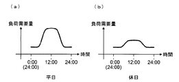
- FIG. 2 is a graph showing the load demand of the load unit provided in the facility, with the horizontal axis representing time and the vertical axis representing the load demand.
- FIG. 2A is a graph showing the load demand on a weekday (working day) of the facility
- FIG. 2B is a graph showing the load demand on a holiday (non-working day) of the facility. .
- the load demand during the daytime (around 12:00) is large on both weekdays and holidays, and the load demand during nighttime (around 24:00) is small.
- the load demand per day is larger on weekdays than on holidays.
- the maximum (peak) load demand amount per unit time and the magnitude of the fluctuation of the load demand amount are larger on weekdays than on holidays. Therefore, the necessity of charging and discharging the power storage unit 11 for leveling power consumption (hereinafter referred to as normal charging / discharging) may be higher on weekdays than on holidays.
- the effect obtained when power consumption is leveled can be greater on weekdays than on holidays.
- FIG. 2 is only an example, and the present invention is applicable regardless of the load demand (for example, even if the peak position is different from that in FIG. 2).
- the capacity learning operation examples described below can be combined and executed as long as no contradiction occurs.
- the facility operation period (period in which the load demand amount per unit period is large) and the non-operation period (period in which the load demand amount per unit period is small)
- the unit period is one day from 0:00 to 24:00
- the weekday shown in FIG. 2A corresponds to the operating period
- the holiday shown in FIG. 2B corresponds to the non-operating period.
- the unit period setting method is not limited to this example.
- the unit period may be one day from 5:00 to 29:00 (next day at 5:00), or may be several hours or several days.
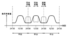
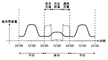
- FIG. 3 is a graph showing a first operation example of capacity learning.
- the vertical axis and horizontal axis of the graph shown in FIG. 3 are the same as those of the graph shown in FIG.
- the solid line in the graph shown in FIG. 3 indicates the load demand similar to that in FIG. 2, and the broken line in the graph shown in FIG. 3 indicates the electric power that is necessary (when above the solid line) due to capacity learning.
- the amount of power is added to the load demand amount, or the amount of electric power that becomes unnecessary (in the case of being below the solid line) is subtracted from the load demand amount, and each is displayed.
- the operation example shown in FIG. 3 is for a case where there is no holiday in the facility.
- the power storage unit 11 is completely discharged during the daytime of a weekday when the load demand is predicted to increase.
- full charge is performed at night just before the day when full discharge is performed.
- the power storage unit 11 is charged (hereinafter referred to as normal charge) in preparation for the discharge of the next weekday.
- normal charge the power storage unit 11 is discharged before the time zone in which the discharge is highly likely to be required. Since it can be made possible, it is preferable.
- the complete charge and complete discharge of the electrical storage part 11 will be performed according to the operation schedule of a plant
- leveling of power consumption can be achieved by performing complete discharge at the above timing. For this reason, it is possible to reduce the electricity rate and reduce the amount of carbon dioxide emissions.
- full charging and normal charging at the above timing it is possible to use nighttime grid power at a low price per unit power.
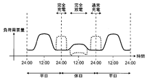
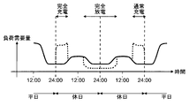
- FIG. 4 is a graph showing a second operation example of capacity learning, which is the same as FIG. 3 showing the first operation example. In the description of FIG. 4 and this operation example, the description of the same parts as those in FIG. 3 and the first operation example is omitted.
- the second operation example shown in FIG. 4 is a case where there is a holiday in the facility.
- the charge / discharge control unit 51 gives priority to holidays as the timing of complete discharge of the power storage unit 11. Therefore, in this operation example, it is assumed that the power storage unit 11 is completely discharged during the holiday. Also, the load demand during the day on holidays is smaller than the load demand during the day on weekdays. Therefore, in this operation example, the amount of electric power discharged per unit time during complete discharge is smaller than that in the first operation example, and the discharge time is longer than that in the first operation example. In this operation example, as in the first operation example, full charging and normal charging are performed at night.
- the complete charge and complete discharge of the electrical storage part 11 will be performed according to the operation plan of a facility similarly to the 1st operation example. Therefore, it is possible to optimize the timing for performing the capacity learning of the power storage unit 11.
- the amount of power discharged per unit time during complete discharge is smaller than that in the first operation example, and the discharge time is longer than that in the first operation example.
- a complete discharge may be performed with the same amount of power and time as in one operation example.
- FIG. 5 is a graph showing another example of the second operation example of capacity learning, which is the same as FIG. In the description of FIG. 5 and this example, the description of the same parts as those in FIG. 4 and the description thereof will be omitted.
- complete discharge is performed during each day of two consecutive holidays. Thereby, it becomes possible to divide the electric energy which must be discharged in order to perform complete discharge into two days. That is, the amount of power per day discharged for complete discharge can be made smaller than when full discharge is performed in one day. However, it is assumed that the power or current discharged on each of the two days off is large enough to be measured by the charge / discharge measurement unit 13.
- This configuration makes it possible to perform complete discharge even when holiday load demand is small and complete discharge is difficult in one day. Moreover, since the necessity of charge / discharge during normal times can be reduced during holidays, complete discharge for capacity learning can be performed flexibly.
- the charge / discharge control unit 51 may determine whether to perform a complete discharge on a day holiday or a complete discharge on a holiday of two days or more based on facility information and load demand information. . For example, when the charge / discharge control unit 51 determines that the holiday load demand is sufficiently large and complete discharge can be performed in one day, the charge / discharge control unit 51 may determine to perform complete discharge in one day holiday. .
- FIG. 6 is a graph showing a third operation example of capacity learning, which is the same as FIG. 4 showing the second operation example. In the description of FIG. 6 and the present operation example, the description of the same parts as those in the description of FIG. 4 and the second operation example will be omitted.
- the charge / discharge control unit 51 gives priority to holidays as the timing of complete discharge of the power storage unit 11, performs complete discharge during holidays, and performs full charge and normal charge.
- the points performed at night are the same as in the second operation example. However, it differs from the second operation example in that full charging and normal charging start and end within the holiday.
- the complete charge and complete discharge of the electrical storage part 11 will be performed according to the operation plan of a facility similarly to the 1st operation example and the 2nd operation example. Therefore, it is possible to optimize the timing for performing the capacity learning of the power storage unit 11.
- capacity learning and post-processing can be completed on a holiday. Therefore, it becomes possible to execute capacity learning without hindering normal charging / discharging on weekdays (particularly, the next day or the day before a holiday on which capacity learning is performed).
- FIG. 7 is a graph showing another example of the third operation example of capacity learning, which is the same as FIG. In the description of FIG. 7 and this example, the description of the same parts as those in FIG. 6 and the description thereof will be omitted.
- complete discharge is performed over two consecutive holidays. Thereby, it becomes possible to divide the electric energy which must be discharged in order to perform complete discharge into two days. That is, the amount of power per day discharged for complete discharge can be made smaller than when full discharge is performed in one day. However, it is assumed that the power or current discharged on each of the two days off is large enough to be measured by the charge / discharge measurement unit 13.
- This configuration makes it possible to perform complete discharge even when holiday load demand is small and complete discharge is difficult in one day. Moreover, since the necessity of charge / discharge during normal times can be reduced during holidays, complete discharge for capacity learning can be performed flexibly.
- the charge / discharge control unit 51 may determine whether to perform a complete discharge on a day holiday or a complete discharge on a holiday of two days or more based on facility information and load demand information. . For example, when the charge / discharge control unit 51 determines that the holiday load demand is sufficiently large and complete discharge can be performed in one day, the charge / discharge control unit 51 may determine to perform complete discharge in one day holiday. .
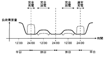
- FIG. 8 is a graph showing a fourth operation example of capacity learning, which is the same as FIG. 4 showing the second operation example. In the description of FIG. 8 and this operation example, the description of the same portions as those in FIG. 4 and the second operation example will be omitted.
- the holiday is given priority as the timing at which the charge / discharge control unit 51 completely discharges the power storage unit 11, as in the second operation example and the third operation example.
- complete discharge is performed by performing discharge separately during the day of the holiday and during the day of the weekday that is the day before the holiday.
- full charge is performed at night just before the daytime on weekdays during which discharge is part of complete discharge.
- the battery is normally charged at night immediately after a holiday on which a discharge that forms part of the complete discharge is performed.
- the power storage unit 11 When configured as described above, as in the first to third operation examples, the power storage unit 11 is fully charged and fully discharged according to the planned operation of the facility. Therefore, it is possible to optimize the timing for performing the capacity learning of the power storage unit 11.
- complete charging and normal charging may be started and ended on weekdays and holidays when complete discharging is performed. If comprised in this way, in the example shown in FIG. 8, the electric storage part 11 of the electrical storage part 11 in the weekday (The day before the weekday when the discharge which forms a part of complete discharge is performed, the day after the holiday when the discharge which forms a part of complete discharge is performed) Capacitance learning can be performed without hindering charging and discharging operations.
- the charge / discharge control unit 51 may determine whether or not to perform this operation example based on the facility information and the load demand information. For example, when the charge / discharge control unit 51 determines that the holiday load demand is not sufficiently large and it is difficult to perform a complete discharge in one day, and the continuous holiday for two days or more cannot be confirmed, It may be decided to perform an operation example.
- complete discharge may be performed by discharging in the order of holidays and weekdays.
- the weekday discharge is performed first as in the former case, the remaining capacity of the power storage unit 11 can be secured after the weekday discharge. For this reason, it is possible to discharge the power storage unit 11 in response to a sudden discharge required on the weekday or in an emergency such as the stop of the supply of system power.
- complete discharge may be performed over weekdays and holidays.
- a complete discharge may be performed on a weekday of two or more days as in this operation example (see FIG. 7 and FIG. 7). (See FIG. 8).
- ⁇ Modification >>
- the capacity learning can be performed even when the power storage unit 11 is fully charged after the complete discharge. it can.
- the full charge in each of the above-described operation examples may not be performed, and the full charge may be performed instead of the normal charge in each of the above-described operation examples.
- the full charge may be performed in two days or more as in the case of the complete discharge in each of the above-described operation examples (see FIGS. 5 and 7). However, as in the above-described operation examples, it is preferable to perform full charging at night.
- a part or all of the operations of the power storage related unit 10 and the control unit 50 may be performed by a control device such as a microcomputer. Further, all or part of the functions realized by such a control device is described as a program, and the program is executed on a program execution device (for example, a computer) to realize all or part of the functions. It doesn't matter if you do.
- the power supply system 1 shown in FIG. 1 is not limited to the above-described case, and can be realized by hardware or a combination of hardware and software. Moreover, when comprising a part of charging system using software, the block about the site
- the present invention can be used in a power supply system that supplies power.
Landscapes
- Engineering & Computer Science (AREA)
- Manufacturing & Machinery (AREA)
- Chemical & Material Sciences (AREA)
- Chemical Kinetics & Catalysis (AREA)
- Electrochemistry (AREA)
- General Chemical & Material Sciences (AREA)
- Power Engineering (AREA)
- Physics & Mathematics (AREA)
- General Physics & Mathematics (AREA)
- Supply And Distribution Of Alternating Current (AREA)
- Charge And Discharge Circuits For Batteries Or The Like (AREA)
- Secondary Cells (AREA)
Abstract
【課題】蓄電部の容量学習を行うタイミングを適切化する電力供給システムを提供する。 【解決手段】電力供給システムは、施設に備えられる負荷に電力を供給するものであり、充電により電力を蓄え放電により電力を供給する蓄電部と、蓄電部の完全充電及び完全放電を順番に行うことで蓄電部の容量を測定する容量測定部と、を備える。容量測定部は、施設の稼働予定を取得し、当該稼働予定に基づいて蓄電部の完全充電及び完全放電を行うタイミングを決定する。
Description
本発明は、電力を供給する電力供給システムに関する。
近年、蓄電池の大容量化が進み、家庭や店舗、ビルなどで消費される電力の貯蔵用としての利用が検討されている。このような蓄電池は、事前に充電する(電力を消費する)ことで、任意のタイミングで放電する(電力を供給する)ことができる。即ち、蓄電池の充電及び放電を行うタイミングを制御することで、系統電力(電力会社から供給される電力。以下同じ。)を消費するタイミングを制御することが可能になる。
一般的に、系統電力の電力料金には、固定性の基本料金と、従量制の使用料金とが含まれる。そして、電力会社は、単位時間に消費する系統電力の電力量の最大値が小さくなるほど、基本料金が安くなるように設定している。また、消費電力が大きくなり得る日中よりも、消費電力が小さくなり得る夜間の方が、使用料金の単位電力当たりの価格が安くなるように設定している。そのため、系統電力の消費者は、電力消費を平準化するほど、電力料金を安くすることができる。そして、電力消費が平準化されると、電力会社が効率良く発電(特に、火力発電)することができるようになるため、発電に伴う二酸化炭素の排出量を削減することが可能になる。
電力消費の平準化は、例えば、単位時間当たりに消費する電力量が瞬間的に大きくなる場合に蓄電池を放電したり、夜間に蓄電池を充電して日中に蓄電池を放電したりすることで、図ることができる。このような蓄電池の充電及び放電の制御を行う場合、蓄電池の残容量を正確に把握して、充電及び放電を行うタイミングや、充電及び放電される電力量を決定すると、効果的に電力消費の平準化を図ることができるため、好ましい。
蓄電池の残容量を把握する方法として、例えば、蓄電池の電圧値に基づいて残容量を推定する方法や、ある状態(例えば、十分に充電された状態)を基準にするとともに、充電及び放電された電流量を積算することで、蓄電池の残容量を推定する方法がある。しかしながら、これらの方法では、蓄電池の使用や時間の経過とともに推定精度が劣化して、正確な残容量が求められなくなるため、問題となる。
この問題を解決する方法として、蓄電池の完全充電及び完全放電を行い、蓄電池の容量を実測により求め直す方法(以下、容量学習とする)がある。この容量学習により蓄電池の容量を定期的に求め直し、求めた蓄電池の容量を上述した蓄電池の残容量の推定方法に反映させることで、蓄電池の残容量を精度良く求めることが可能になる。
例えば、特許文献1では、ユーザによって容量学習を行うことが指示されると、蓄電池が備えられるシステムの消費電力を最大化することで、蓄電池の完全放電を迅速に行う容量学習方法が提案されている。
特許文献1で提案されている容量学習方法によれば、任意のタイミングで迅速に容量学習を行うことができる。しかしながら、蓄電池の完全放電を迅速に行うために、無用に電力を消費せざるを得ない場合があるため、問題となる。さらに、この完全放電が、蓄電池の放電が必要になるタイミングの直前に行われると、当該タイミングで予定通りに蓄電池を放電させることが困難になる。そのため、電力消費の平準化を阻害し、電力料金の低減化や二酸化炭素の排出量の削減を図ることが困難になるため、問題となる。
そこで本発明は、蓄電部の容量学習を行うタイミングを適切化する電力供給システムを提供することを目的とする。
上記目的を達成するために、本発明における電力供給システムは、施設に備えられる負荷に電力を供給する電力供給システムであって、充電により電力を蓄え、放電により電力を供給する蓄電部と、前記蓄電部の完全充電及び完全放電を順番に行うことで、前記蓄電部の容量を測定する容量測定部と、を備え、前記容量測定部が、前記施設の稼働予定を取得し、当該稼働予定に基づいて前記蓄電部の完全充電及び完全放電を行うタイミングを決定することを特徴とする。
以下の実施の形態では、容量測定部として、充放電制御部、充放電処理部、充放電測定部及び容量学習部を例に挙げて説明している。
また、上記構成の電力供給システムにおいて、前記施設の稼働予定を前記容量測定部に提供する施設情報提供部をさらに備えても構わない。また、上記構成の電力供給システムにおいて、前記容量測定部が、前記蓄電部が完全充電されてから完全放電されるまでに放電される電力及び電流の少なくとも一方を測定する、または、前記蓄電部が完全放電されてから完全充電されるまでに充電される電力及び電流の少なくとも一方を測定することで、前記蓄電部の容量を測定しても構わない。
また、上記構成の電力供給システムにおいて、前記施設に、単位期間当たりに前記負荷が消費する電力量が大きい稼働期間と、単位期間当たりに前記負荷が消費する電力量が小さい非稼働期間と、があり、前記容量測定部が、前記蓄電部の完全放電を行うタイミングとして、非稼働期間を優先しても構わない。
このように構成すると、電力消費の平準化を図るための蓄電部の充電及び放電の必要性が低くなり得る非稼働期間に、完全放電を行うこととなる。そのため、容量学習を行うことによって、電力消費の平準化を図るための蓄電部の充電及び放電の必要性が高くなり得る稼働期間に、当該充電及び放電の実行が困難になる(例えば、蓄電部の放電が制限される)ことを、抑制することが可能となる。
また、上記構成の電力供給システムにおいて、前記負荷で消費される電力量を予測する負荷需要量予測部をさらに備え、前記負荷需要量予測部により、1つの非稼働期間に前記負荷で消費される電力量が、前記蓄電部の完全放電により供給される電力量よりも小さくなることが予測される場合、前記容量測定部は、当該非稼働期間と、他の非稼働期間及び稼働期間の少なくとも1つと、で前記蓄電部の完全放電を行っても構わない。
このように構成すると、非稼働期間の負荷需要量が小さく、当該期間では完全放電が困難である場合などでも、完全放電を行うことが可能になる。
また、上記構成の電力供給システムにおいて、前記容量測定部は、1つの非稼働期間内、または、連続する複数の非稼働期間内で、前記蓄電部の完全充電及び完全放電を開始しかつ終了しても構わない。
このように構成すると、容量学習を非稼働期間で完結することができる。そのため、稼働期間における、電力消費の平準化を図るための蓄電部の充電及び放電を妨げることなく、容量学習を実行することが可能になる。
また、上記構成の電力供給システムにおいて、前記負荷で消費される電力量を予測する負荷需要量予測部をさらに備え、前記容量測定部は、前記蓄電部の完全充電の後に完全放電を行うものであり、当該完全放電の後であり、かつ、直後の稼働期間内で、前記負荷需要量予測部により前記負荷で消費される単位時間当たりの電力量が他よりも大きくなると予測される時間帯よりも前に、前記蓄電部が充電されることとしても構わない。
このように構成すると、放電が必要とされる可能性が高い時間帯よりも前に、蓄電部を放電可能な状態にすることができる。
また、上記構成の電力供給システムにおいて、前記容量測定部は、1つの非稼働期間内、または、連続する複数の非稼働期間内に、前記蓄電部の完全充電、完全放電及び充電をこの順で行い、それぞれを当該期間内で開始しかつ終了しても構わない。
このように構成すると、容量学習やその事後処理を、非稼働期間で完結することができる。そのため、稼働期間における、電力消費の平準化を図るための蓄電部の充電及び放電を妨げることなく、容量学習を実行することが可能になる。
また、上記構成の電力供給システムにおいて、前記負荷で消費される電力量を予測する負荷需要量予測部をさらに備え、前記容量測定部が、前記負荷需要量予測部により前記負荷で消費される単位時間当たりの電力量が小さくなると予測される時間帯に、前記蓄電部の完全充電を行い、前記負荷需要量予測部により前記負荷で消費される単位時間当たりの電力量が大きくなると予測される時間帯に、前記蓄電部の完全放電を行っても構わない。
このように構成すると、電力消費の平準化を図ることができる。そのため、電力料金の低減化及び二酸化炭素の排出量の削減を図ることが可能となる。
本発明の構成とすると、施設の稼働予定に合わせて蓄電部の完全充電及び完全放電が行われる。そのため、蓄電部の容量学習を行うタイミングを適切化することが可能となる。
本発明の意義ないし効果は、以下に示す実施の形態の説明によりさらに明らかとなろう。ただし、以下の実施の形態は、あくまでも本発明の実施の形態の一つであって、本発明ないし各構成要件の用語の意義は、以下の実施の形態に記載されたものに制限されるものではない。
本発明の実施の一形態である電力供給システムについて、以下図面を参照して説明する。
<<電力供給システムの構成>>
まず、本発明の実施の一形態である電力供給システムの構成の一例について、図面を参照して説明する。図1は、本発明の実施の一形態である電力供給システムの構成例を示すブロック図である。なお、図中の各ブロックを接続する実線の矢印は電力のやり取りを示し、破線の矢印は情報のやり取りを示している。
<<電力供給システムの構成>>
まず、本発明の実施の一形態である電力供給システムの構成の一例について、図面を参照して説明する。図1は、本発明の実施の一形態である電力供給システムの構成例を示すブロック図である。なお、図中の各ブロックを接続する実線の矢印は電力のやり取りを示し、破線の矢印は情報のやり取りを示している。
図1に示す電力供給システム1は、供給される電力を充電により蓄えるとともに放電により電力を供給する蓄電部11を備える蓄電関連部10と、太陽光発電により電力を供給する太陽光発電部20と、電力を消費する負荷部31を備える負荷関連部30と、電力の授受を調整するパワーコンディショナ(以下、パワコンとする)40と、各部の動作を制御する制御部50と、制御部50が取得し得る各種情報を記録するデータベース60と、負荷部31が備えられる施設(例えば、店舗、ビル、工場など、全体として電力を消費し得るもの)の稼働予定や現在時刻などを示す施設情報を制御部50に入力する施設情報提供部70と、を備える。
蓄電関連部10は、蓄電部11と、蓄電部11の充電及び放電を行う充放電処理部12と、蓄電部11に充電される電力または電流や蓄電部11から放電される電力または電流を測定する充放電測定部13と、容量学習により蓄電部11の容量を求める容量学習部14と、容量学習部14で求められる蓄電部11の容量と充放電測定部13の測定結果とから蓄電部11の残容量を推定する残容量推定部15と、を備える。
蓄電部11は、例えば大容量の蓄電池から成り、充放電処理部12により充電及び放電が行われる。充放電測定部13は、例えば、単位時間(例えば、1分)当たりに蓄電部11に充電される電力量または電流量や、単位時間当たりに蓄電部11から放電される電力量または電流量を測定する。なお、充放電測定部13が測定した結果を示す情報(以下、充放電情報とする)は、制御部50に入力され得る。
容量学習部14は、蓄電部11が完全充電された状態(例えば、不可逆反応が生じる過充電状態の直前の状態、または、当該状態に対して所定の余裕を有する状態まで充電した状態。以下同じ。)から完全放電された状態(例えば、不可逆反応が生じる過放電状態の直前の状態、または、当該状態に対して所定の余裕を有する状態まで放電した状態。以下同じ。)に至るまでに放電した電力または電流の積分値から、蓄電部11の容量を求める。この積分値は、充放電測定部13の測定結果から得ることができる。
蓄電部11の完全充電及び完全放電は、順番に行われる。なお、上記の求め方の順番とは逆に、容量学習部14が、蓄電部11が完全放電された状態から完全充電された状態に至るまでに充電した電力または電流の積分値から、蓄電部11の容量を求めても構わない。また、蓄電部11の完全充電及び完全放電の少なくとも一方が複数回に分けて行われることで、蓄電部11が完全充電または完全放電された状態になることとしても構わない。ただし、完全充電及び完全放電のうち、後に行われる方が複数回に分けて行われる場合、分けられたそれぞれの動作の間で反対の動作(完全充電が後かつ複数回に分けられて行われる場合は放電、完全放電が後かつ複数回に分けられて行われる場合は充電)が行われないようにすると、蓄電部11の容量を精度よく求めることができるため、好ましい。また、容量学習部14が求めた容量を示す情報(以下、容量情報とする)は、制御部50に入力され得る。
残容量推定部15は、容量学習部14から得られる蓄電部11の容量を基準として、充放電測定部13で測定される電力または電流の積分値を、加算(充電時)または減算(放電時)することで、蓄電部11の残容量を推定する。なお、残容量推定部15が、蓄電部11の電圧値と蓄電部11の残容量との関係を示すテーブルを備え、蓄電部11の電圧値を測定するとともに当該テーブルを参照することで、蓄電部11の残容量を推定しても構わない。この場合、容量学習部14から得られる蓄電部11の容量を、テーブルの値に反映させても構わない。また、残容量推定部15が推定した残容量を示す情報(以下、残容量情報とする)は、制御部50に入力され得る。
太陽光発電部20は、例えば屋外に設置される太陽光発電パネルから成り、照射される光(日光)を電力に変換することで発電する。
負荷関連部30は、負荷部31と、供給される電力を必要に応じて負荷部31に供給する分電部32と、を備える。なお、負荷部31及び分電部32の少なくとも一方は、負荷部31に供給されて消費される単位時間(例えば、1分)当たりの電力量または電流量を測定可能である。なお、負荷部31及び分電部32の少なくとも一方が測定した結果を示す情報(以下、負荷需要量情報とする)は、制御部50に入力され得る。
負荷部31は、供給される電力を消費する複数の機器(負荷)から成る。例えば、電灯などの照明装置や、空調装置、冷機及び暖機、電動車両(Electric Vehicle)の駆動用のバッテリを充電するEV充電装置などが含まれ得る。分電部32は、系統電力やパワコン40から供給される電力を、負荷部31を構成するそれぞれの負荷に対して選択的に供給する。
パワコン40は、入力される直流電力を所定の直流電力に変換して出力する太陽光発電部用コンバータ41と、入力される交流電力または直流電力を所定の直流電力または交流電力に変換して出力するインバータ42と、入力される直流電力を所定の直流電力に変換して出力する蓄電部用コンバータ43と、太陽光発電部20の発電により供給される電力または電流を測定する発電測定部44と、を備える。
太陽光発電部用コンバータ41は、太陽光発電部20が供給する直流電力を、インバータ42や蓄電部用コンバータ43での処理に適した直流電力に変換して出力する。インバータ42は、分電部32を介して入力される交流の系統電力を、蓄電部用コンバータ43での処理に適した直流電力に変換して出力する。また、インバータ42は、太陽光発電部用コンバータ41から出力される直流電力や、蓄電部用コンバータ43から出力される直流電力を、分電部32や負荷部31での処理に適した交流電力に変換して、分電部32に出力する。蓄電部用コンバータ43は、太陽光発電部用コンバータ41から出力される直流電力や、インバータ42から出力される直流電力を、蓄電部11の充電に適した直流電力に変換して、蓄電部11に出力する。また、蓄電部用コンバータ43は、蓄電部11の放電により供給される直流電力を、インバータ42での処理に適した直流電力に変換して出力する。発電測定部44は、太陽光発電部20から出力されて太陽光発電部用コンバータ41に入力される直流電力の、単位時間(例えば、1分)当たりの電力量または電流量を測定する。なお、発電測定部44が測定した結果を示す情報(以下、発電量情報とする)は、制御部50に入力され得る。
制御部50は、充放電処理部12の動作を制御する充放電制御部51と、太陽光発電部20で発電される電力量を予測する発電量予測部52と、負荷部31に供給されて消費される電力量を予測する負荷需要量予測部53と、を備える。なお、制御部50の一部または全部は、パワコン40内に設置されても構わないし、パワコン40と独立して設置されても構わない。
また、制御部50は、上述のように入力される各情報を、必要に応じてデータベース60に記録する。また、制御部50は、データベース60に記録された情報を、必要に応じて読み出す。なお、データベース60が、他の電力供給システムなど外部で生成された各情報を、記録可能であっても構わない。
充放電制御部51は、発電量予測部52で予測される太陽光発電部20が発電する電力量(以下、発電量とする)や、負荷需要量予測部53で予測される負荷部31が消費する電力量(以下、負荷需要量とする)に基づいて、蓄電部11を充電及び放電するタイミングを決定し、充放電処理部12を制御する。これにより、電力消費の平準化を図るための蓄電部11の充電及び放電が行われる。
また、具体例については後述するが、充放電制御部51は、負荷需要量予測部53で予測される負荷需要量や、施設情報提供部70から取得する施設情報に基づいて、容量学習を行うタイミング(蓄電部11の完全充電及び完全放電を行うタイミングなど)を決定する。
発電量予測部52及び負荷需要量予測部53は、予測時に取得した発電量情報や負荷需要量情報だけでなく、データベース60に記録されている情報(例えば、過去に取得及び記録された発電量情報及び負荷需要量情報や、これらを統計的に処理(例えば、1週間や1ヶ月などの所定の期間で平均化)した情報など)をも参照し得る。そして、これらの情報を参照することで、発電量や負荷需要量を予測する。
なお、図1に示す電力供給システム1の構成は一例に過ぎず、他の構成としても構わない。例えば、インバータ42の代わりに、太陽光発電部用コンバータ41から出力される直流電力を交流電力に変換して分電部32に入力する太陽光発電部用インバータと、蓄電部用コンバータ43から出力される直流電力を交流電力に変換して分電部32に入力するとともに分電部32を介して入力される交流電力を直流電力に変換して蓄電部用コンバータ43に入力する蓄電部用インバータと、のそれぞれを備える構成としても構わない。さらに、この蓄電部用インバータの代わりに、蓄電部用コンバータ43から出力される直流電力を交流電力に変換して分電部32に入力する放電用インバータと、分電部32を介して入力される交流電力を直流電力に変換して蓄電部用コンバータ43に入力する充電用インバータと、のそれぞれを備える構成としても構わない。
また、各ブロックの包含関係は、説明の便宜のための一例に過ぎず、これ以外の関係であっても構わない。例えば、充放電測定部13や充放電処理部12が、パワコン40に含まれても(蓄電関連部10に含まれなくても)構わない。また例えば、蓄電部用コンバータ43が、蓄電関連部10に含まれても(パワコン40に含まれなくても)構わない。また例えば、発電測定部44が、太陽光発電部20側に含まれても(パワコン40に含まれなくても)構わない。また例えば、容量学習部14や残容量推定部15が、制御部50に含まれても(蓄電関連部10に含まれなくても)構わない。
また、制御部50が、ネットワークなどを介して現在または将来の天気に関する情報(例えば、日照の有無や気温、湿度、降水量など)を取得しても構わないし、天気に関する情報を生成する観測機器を備え、当該観測機器から天気に関する情報を取得しても構わない。また、制御部50が、取得した天気に関する情報をデータベース60に記録しても構わない。また、制御部50が、時間に関する情報を生成したり施設情報提供部70から取得したりしても構わないし、生成または取得した時間に関する情報をデータベース60に記録しても構わない。このように構成すると、発電量予測部52や負荷需要量予測部53が、天気や時間に基づいた予測をも行うことが可能となる。そのため、さらに精度良く予測をすることが可能となる。
また、太陽光発電により電力を供給する太陽光発電部20に代えて(または、加えて)、他の方法で電力を供給する発電部(例えば、燃料電池や発電機など)を備えても構わないし、これらの発電部や太陽光発電部20を備えない構成としても構わない。また、蓄電部11が配置される空間の温度を調整する空冷ファンやエアコンディショナなどから成る温度調整部と、当該空間の温度を検出するサーミスタや熱電対などから成る温度センサと、を蓄電関連部10に備え、蓄電部11の温度調整を行っても構わない。
また、施設情報提供部70は、事前にユーザによって入力された稼働予定が記録された記録装置のようなものであっても構わない。また、完全充電及び完全放電を行うタイミングの決定時など、必要時にユーザが稼働予定を入力する操作装置のようなものであっても構わない。
<<容量学習>>
次に、図1に示した電力供給システム1による、容量学習の動作例について、図面を参照して説明する。最初に、施設に備えられる負荷部31の負荷需要量について、図面を参照して説明する。図2は、施設に備えられる負荷部の負荷需要量を示すグラフであり、横軸が時間、縦軸が負荷需要量をそれぞれ示している。また、図2(a)は、施設の平日(稼働日)における負荷需要量を示すグラフであり、図2(b)は、施設の休日(非稼働日)における負荷需要量を示すグラフである。
<<容量学習>>
次に、図1に示した電力供給システム1による、容量学習の動作例について、図面を参照して説明する。最初に、施設に備えられる負荷部31の負荷需要量について、図面を参照して説明する。図2は、施設に備えられる負荷部の負荷需要量を示すグラフであり、横軸が時間、縦軸が負荷需要量をそれぞれ示している。また、図2(a)は、施設の平日(稼働日)における負荷需要量を示すグラフであり、図2(b)は、施設の休日(非稼働日)における負荷需要量を示すグラフである。
図2(a),(b)に示すように、平日及び休日ともに、日中(12時前後)の負荷需要量が大きく、夜間(24時前後)の負荷需要量が小さい。ただし、一日当たりの負荷需要量は、休日よりも平日の方が大きい。また、単位時間当たり最大の(ピークの)負荷需要量や負荷需要量の変動の大きさについても、休日よりも平日の方が大きい。そのため、休日よりも平日の方が、電力消費の平準化を図るための蓄電部11の充電及び放電(以下、通常時充放電とする)の必要性が、高くなり得る。また、休日よりも平日の方が、電力消費の平準化を行った場合に得られる効果が、大きくなり得る。
以下では、施設に備えられる負荷部31の負荷需要量が図2に示すものであるとして、電力供給システム1の容量学習の各動作例を具体化して説明する。しかし、図2は一例に過ぎず、負荷需要量がどのようなものであっても(例えば、ピークの位置が図2と異なるものであっても)、本発明は適用可能である。また、以下説明する容量学習の各動作例は、矛盾無き限り組み合わせて実行可能である。
また、以下説明する容量学習の各動作例の中には、施設の稼働期間(単位期間当たりの負荷需要量が大きい期間)と、非稼働期間(単位期間当たりの負荷需要量が小さい期間)とに基づいて、容量学習を行うタイミングを決定するものがある。そのような動作例については、単位期間が0時~24時の一日であり、図2(a)に示す平日が稼働期間、図2(b)に示す休日が非稼働期間にそれぞれ相当するものとして、具体的に説明する。しかし、単位期間の設定方法はこの例に限られるものではない。例えば、単位期間を5時~29時(翌日5時)の一日としても構わないし、数時間や数日としても構わない。ただし、図2(a),(b)に示すように、稼働期間及び非稼働期間の負荷需要量が対照的になるように単位期間を設定すると、好ましい。また、多くの施設は一日単位で稼働の有無が管理されるため、単位期間を一日にすると好ましい。
<第1動作例>
容量学習の第1動作例について、図面を参照して説明する。図3は、容量学習の第1動作例について示したグラフである。図3に示すグラフの縦軸及び横軸は、図2に示すグラフと同様である。また、図3に示すグラフの実線は、図2と同様の負荷需要量を示すものであり、図3に示すグラフの破線は、容量学習によって必要(実線よりも上側になる場合)になる電力量を負荷需要量に加算して、または、不要(実線よりも下側になる場合)になる電力量を負荷需要量から減算して、それぞれ表示したものである。
<第1動作例>
容量学習の第1動作例について、図面を参照して説明する。図3は、容量学習の第1動作例について示したグラフである。図3に示すグラフの縦軸及び横軸は、図2に示すグラフと同様である。また、図3に示すグラフの実線は、図2と同様の負荷需要量を示すものであり、図3に示すグラフの破線は、容量学習によって必要(実線よりも上側になる場合)になる電力量を負荷需要量に加算して、または、不要(実線よりも下側になる場合)になる電力量を負荷需要量から減算して、それぞれ表示したものである。
図3に示す動作例は、施設に休日が無い場合のものである。この場合、負荷需要量が大きくなると予測される平日の日中に、蓄電部11の完全放電を行う。また、完全放電を行う日中の直前の夜間に、完全充電を行う。
また、完全放電を行う日中の直後の夜間に、翌日である平日の放電に備え、蓄電部11の充電(以下、通常充電とする)を行う。このように、蓄電部11の完全放電後であり、直後の平日の日中までに通常充電を行うと、放電が必要とされる可能性が高い時間帯よりも前に、蓄電部11を放電可能な状態にすることができるため、好ましい。
以上のように構成すると、施設の稼働予定に合わせて蓄電部11の完全充電及び完全放電が行われる。そのため、蓄電部11の容量学習を行うタイミングを適切化することが可能となる。
さらに、上記のタイミングで完全放電を行うことにより、電力消費の平準化を図ることができる。そのため、電力料金の低減化及び二酸化炭素の排出量の削減を図ることが可能となる。また、上記のタイミングで完全充電及び通常充電を行うことで、単位電力当たりの価格が安い夜間の系統電力を利用することができる。
なお、図3に示す例では、通常充電を平日の夜間に行うものとしているが、通常充電を
平日の夜間までに行う(即ち、図3に示すタイミングよりも早期に行う)こととしても構
わない。蓄電部11に充電された電力は、災害などによる系統電力の供給停止時における
非常用の電力源としても利用され得る。そのため、完全放電後かつ夜間までに通常充電を
行うことで、夜間の系統電力の供給停止時において、照明やその他の負荷に電力を供給す
ることが可能となる。
<第2動作例>
次に、容量学習の第2動作例について、図面を参照して説明する。図4は、容量学習の第2動作例について示したグラフであり、第1動作例について示した図3と同様のものである。なお、図4及び本動作例の説明において、図3及び第1動作例の説明と同様となる部分については、説明を省略する。
図4に示す第2動作例は、施設に休日がある場合のものである。本動作例では、充放電制御部51が、蓄電部11の完全放電を行うタイミングとして、休日を優先する。そのため、本動作例では、休日の日中に蓄電部11の完全放電が行われるものとしている。また、休日の日中の負荷需要量は、平日の日中の負荷需要量よりも小さい。そのため、本動作例では、完全放電時の単位時間当たりに放電する電力量が第1動作例よりも小さく、放電時間が第1動作例よりも長くなるものとしている。また、本動作例では、第1動作例と同様に、完全充電及び通常充電が夜間に行われるものとしている。
以上のように構成すると、第1動作例と同様に、施設の稼働予定に合わせて蓄電部11の完全充電及び完全放電が行われる。そのため、蓄電部11の容量学習を行うタイミングを適切化することが可能となる。
さらに、上記のタイミングで完全放電を行うことにより、通常時充放電の必要性が低くなり得る休日に、完全放電を行うこととなる。そのため、容量学習を行うことによって、通常時充放電の必要性が高くなり得る平日に、通常時充放電の実行が困難になる(例えば、蓄電部11の放電が制限される)ことを、抑制することが可能となる。また、上記のタイミングで完全充電及び通常充電を行うことで、単位電力当たりの価格が安い夜間の系統電力を利用することができる。
なお、本動作例において、完全放電時の単位時間当たりに放電する電力量が、第1動作例よりも小さく、放電時間が第1動作例よりも長くなるものとしたが、可能であれば第1動作例と同様の電力量及び時間で完全放電を行っても構わない。
また、休日が連続して二日以上ある場合、二日以上にわたって完全放電を行っても構わないし(例えば、図7参照)、二回以上に分けて放電を行うことで完全放電を行っても構わない。後者の場合の動作例を、図5を参照して説明する。図5は、容量学習の第2動作例の別例について示したグラフであり、図4と同様のものである。なお、図5及び本別例の説明において、図4及びその説明と同様となる部分については、説明を省略する。
本別例では、二日連続する休日のそれぞれの日中で、完全放電を行う。これにより、完全放電を行うために放電しなければならない電力量を、二日に分けることが可能となる。即ち、完全放電のために放電する一日当たりの電力量を、一日で完全放電を行う場合よりも、小さくすることが可能となる。ただし、二日の休日のそれぞれで放電される電力または電流は、充放電測定部13で測定可能な程度に大きいものとする。
このように構成すると、休日の負荷需要量が小さく、一日では完全放電が困難である場合などでも、完全放電を行うことが可能になる。また、休日であれば、通常時充放電の必要性が低くなり得るため、容量学習のための完全放電を柔軟に行うことができる。
また、充放電制御部51が、施設情報や負荷需要量情報に基づいて、一日の休日で完全放電を行うか、二日以上の休日で完全放電を行うか、を決定しても構わない。例えば、充放電制御部51が、休日の負荷需要量が十分大きく一日で完全放電を行うことができると判定する場合に、一日の休日で完全放電を行うことを決定しても構わない。また例えば、充放電制御部51が、休日の負荷需要量が十分大きくなく一日で完全放電を行うことが困難であると判定する場合でも、二日以上の連続した休日を確認して、当該二日以上の休日に放電すれば完全放電を行うことができると判定する場合に、当該二日以上の休日で完全放電を行うことを決定しても構わない。
<第3動作例>
次に、容量学習の第3動作例について、図面を参照して説明する。図6は、容量学習の第3動作例について示したグラフであり、第2動作例について示した図4と同様のものである。なお、図6及び本動作例の説明において、図4及び第2動作例の説明と同様となる部分については、説明を省略する。
<第3動作例>
次に、容量学習の第3動作例について、図面を参照して説明する。図6は、容量学習の第3動作例について示したグラフであり、第2動作例について示した図4と同様のものである。なお、図6及び本動作例の説明において、図4及び第2動作例の説明と同様となる部分については、説明を省略する。
図6に示す第3動作例は、充放電制御部51が、蓄電部11の完全放電を行うタイミングとして休日を優先する点や、完全放電を休日の日中に行うとともに完全充電及び通常充電を夜間に行う点については、第2動作例と同様である。しかしながら、完全充電や通常充電を、当該休日内で開始しかつ終了する点が、第2動作例と異なる。
以上のように構成すると、第1動作例及び第2動作例と同様に、施設の稼働予定に合わせて蓄電部11の完全充電及び完全放電が行われる。そのため、蓄電部11の容量学習を行うタイミングを適切化することが可能となる。
さらに、上記のタイミングで完全放電を行うことにより、通常時充放電の必要性が低くなり得る休日に、完全放電を行うこととなる。そのため、容量学習を行うことによって、通常時充放電の必要性が高くなり得る平日に、通常時充放電の実行が困難になる(例えば、蓄電部11の放電が制限される)ことを、抑制することが可能となる。また、上記のタイミングで完全充電及び通常充電を行うことで、単位電力当たりの価格が安い夜間の系統電力を利用することができる。
また、上記のタイミングで完全放電、完全充電及び通常充電を行うことで、容量学習やその事後処理を休日で完結することができる。そのため、平日(特に、容量学習を行う休日の翌日や前日)における通常時充放電を妨げることなく、容量学習を実行することが可能になる。
なお、休日が連続して二日以上ある場合、二回以上に分けて放電を行うことで完全放電を行っても構わないし(例えば、図5参照)、二日以上にわたって完全放電を行っても構わない。後者の場合の動作例を、図7を参照して説明する。図7は、容量学習の第3動作例の別例について示したグラフであり、図6と同様のものである。なお、図7及び本別例の説明において、図6及びその説明と同様となる部分については、説明を省略する。
本別例では、二日連続する休日にわたって、完全放電を行う。これにより、完全放電を行うために放電しなければならない電力量を、二日に分けることが可能となる。即ち、完全放電のために放電する一日当たりの電力量を、一日で完全放電を行う場合よりも、小さくすることが可能となる。ただし、二日の休日のそれぞれで放電される電力または電流は、充放電測定部13で測定可能な程度に大きいものとする。
このように構成すると、休日の負荷需要量が小さく、一日では完全放電が困難である場合などでも、完全放電を行うことが可能になる。また、休日であれば、通常時充放電の必要性が低くなり得るため、容量学習のための完全放電を柔軟に行うことができる。
また、充放電制御部51が、施設情報や負荷需要量情報に基づいて、一日の休日で完全放電を行うか、二日以上の休日で完全放電を行うか、を決定しても構わない。例えば、充放電制御部51が、休日の負荷需要量が十分大きく一日で完全放電を行うことができると判定する場合に、一日の休日で完全放電を行うことを決定しても構わない。また例えば、充放電制御部51が、休日の負荷需要量が十分大きくなく一日で完全放電を行うことが困難であると判定する場合でも、二日以上の連続した休日を確認して、当該二日以上の休日に放電すれば完全放電を行うことができると判定する場合に、当該二日以上の休日で完全放電を行うことを決定しても構わない。
<第4動作例>
上述の第2動作例及び第3動作例において、休日の負荷需要量が小さく一日では完全放電が困難であるが、二日以上の連続した休日がない場合の動作例について、以下図面を参照して説明する。図8は、容量学習の第4動作例について示したグラフであり、第2動作例について示した図4と同様のものである。なお、図8及び本動作例の説明において、図4及び第2動作例の説明と同様となる部分については、説明を省略する。
<第4動作例>
上述の第2動作例及び第3動作例において、休日の負荷需要量が小さく一日では完全放電が困難であるが、二日以上の連続した休日がない場合の動作例について、以下図面を参照して説明する。図8は、容量学習の第4動作例について示したグラフであり、第2動作例について示した図4と同様のものである。なお、図8及び本動作例の説明において、図4及び第2動作例の説明と同様となる部分については、説明を省略する。
図8に示す第4動作例は、第2動作例及び第3動作例と同様に、充放電制御部51が、蓄電部11の完全放電を行うタイミングとして休日を優先する。ただし、上記のように休日が1日しかなく、当該休日のみでは完全放電を行うことが困難である。そこで、本動作例では、休日の日中と、当該休日の前日である平日の日中と、に分けて放電を行うことで、完全放電を行う。
さらに、完全放電の一部を成す放電を行う平日の日中の、直前の夜間に、完全充電を行う。また、完全放電の一部を成す放電を行う休日の日中の、直後の夜間に、通常充電を行う。
以上のように構成すると、第1動作例~第3動作例と同様に、施設の稼働予定に合わせて蓄電部11の完全充電及び完全放電が行われる。そのため、蓄電部11の容量学習を行うタイミングを適切化することが可能となる。
さらに、上記のタイミングで完全放電を行うことにより、休日の負荷需要量が小さく一日では完全放電が困難である場合などでも、完全放電を行うことが可能になる。また、上記のタイミングで完全充電及び通常充電を行うことで、単位電力当たりの価格が安い夜間の系統電力を利用することができる。
なお、第3動作例と同様に、完全充電及び通常充電を、完全放電が行われる平日及び休日内で開始しかつ終了しても構わない。このように構成すると、平日(図8に示す例では、完全放電の一部を成す放電が行われる平日の前日、完全放電の一部を成す放電が行われる休日の翌日)における蓄電部11の充電及び放電動作を妨げることなく、容量学習を実行することが可能になる。
また、充放電制御部51が、施設情報や負荷需要量情報に基づいて、本動作例を行うか否かを決定しても構わない。例えば、充放電制御部51が、休日の負荷需要量が十分大きくなく一日で完全放電を行うことが困難であると判定する場合で、二日以上の連続した休日を確認できない場合に、本動作例を行うことを決定しても構わない。
また、平日、休日の順に放電を行うことで完全放電を行う場合を例示したが、休日、平日の順に放電を行うことで完全放電を行っても構わない。ただし、前者のように平日の放電を先に行うと、当該平日の放電後に蓄電部11の残容量を確保することが可能となる。そのため、当該平日に急な放電が必要となる場合や、系統電力の供給が停止するなどの非常時に、蓄電部11を放電して対応することが可能になる。
また、図7に示した動作例と同様に、平日及び休日にわたって、完全放電を行っても構わない。また、第1動作例において、一日の平日で完全放電をすることが困難である場合も、本動作例と同様に、二日以上の平日で完全放電を行っても構わない(図7及び図8参照)。
<<変形例>>
上述の各動作例では、蓄電部11の完全充電の後に完全放電を行う場合について説明したが、上述の通り、蓄電部11の完全放電の後に完全充電を行う場合でも、容量学習を行うことができる。この場合、上述の各動作例における完全充電を行わず、上述の各動作例における通常充電の代わりに完全充電を行うこととしても構わない。
<<変形例>>
上述の各動作例では、蓄電部11の完全充電の後に完全放電を行う場合について説明したが、上述の通り、蓄電部11の完全放電の後に完全充電を行う場合でも、容量学習を行うことができる。この場合、上述の各動作例における完全充電を行わず、上述の各動作例における通常充電の代わりに完全充電を行うこととしても構わない。
また、一日で完全充電を行うことが困難である場合(例えば、完全充電を行うことで、系統電力の単位時間当たりの電力量の最大値が更新される場合や、夜間だけでなく日中も充電する必要が生じる場合など)は、上述の各動作例の完全放電と同様に、二日以上で完全充電を行っても構わない(図5及び図7参照)。ただし、上述の各動作例と同様に、夜間に完全充電を行うこととすると、好ましい。
本発明の実施の一形態における電力供給システム1について、蓄電関連部10や制御部50などの一部または全部の動作を、マイコンなどの制御装置が行うこととしても構わない。さらに、このような制御装置によって実現される機能の全部または一部をプログラムとして記述し、該プログラムをプログラム実行装置(例えばコンピュータ)上で実行することによって、その機能の全部または一部を実現するようにしても構わない。
また、上述した場合に限らず、図1に示す電力供給システム1は、ハードウェア、或いは、ハードウェアとソフトウェアの組み合わせによって実現可能である。また、ソフトウェアを用いて充電システムの一部を構成する場合、ソフトウェアによって実現される部位についてのブロックは、その部位の機能ブロックを表すこととする。
以上、本発明における実施の一形態について説明したが、本発明の範囲はこれに限定されるものではなく、発明の主旨を逸脱しない範囲で種々の変更を加えて実行することができる。
本発明は、電力を供給する電力供給システムに利用可能である。
1 電力供給システム
11 蓄電部
12 充放電処理部
13 充放電測定部
14 容量学習部
15 残容量推定部
31 負荷部
51 充放電制御部
53 負荷需要量予測部
60 データベース
70 施設情報提供部
11 蓄電部
12 充放電処理部
13 充放電測定部
14 容量学習部
15 残容量推定部
31 負荷部
51 充放電制御部
53 負荷需要量予測部
60 データベース
70 施設情報提供部
Claims (6)
- 施設に備えられる負荷に電力を供給する電力供給システムであって、
充電により電力を蓄え、放電により電力を供給する蓄電部と、
前記蓄電部の完全充電及び完全放電を順番に行うことで、前記蓄電部の容量を測定する容量測定部と、を備え、
前記容量測定部が、前記施設の稼働予定を取得し、当該稼働予定に基づいて前記蓄電部の完全充電及び完全放電を行うタイミングを決定することを特徴とする電力供給システム。 - 前記施設に、単位期間当たりに前記負荷が消費する電力量が大きい稼働期間と、単位期間当たりに前記負荷が消費する電力量が小さい非稼働期間と、があり、
前記容量測定部が、前記蓄電部の完全放電を行うタイミングとして、非稼働期間を優先することを特徴とする請求項1に記載の電力供給システム。 - 前記負荷で消費される電力量を予測する負荷需要量予測部をさらに備え、
前記負荷需要量予測部により、1つの非稼働期間に前記負荷で消費される電力量が、前記蓄電部の完全放電により供給される電力量よりも小さくなることが予測される場合、
前記容量測定部は、当該非稼働期間と、他の非稼働期間及び稼働期間の少なくとも1つと、で前記蓄電部の完全放電を行うことを特徴とする請求項2に記載の電力供給システム。 - 前記負荷で消費される電力量を予測する負荷需要量予測部をさらに備え、
前記容量測定部は、前記蓄電部の完全充電の後に完全放電を行うものであり、
当該完全放電の後であり、かつ、直後の稼働期間内で、前記負荷需要量予測部により前記負荷で消費される単位時間当たりの電力量が他よりも大きくなると予測される時間帯よりも前に、前記蓄電部が充電されることを特徴とする請求項2に記載の電力供給システム。 - 前記負荷で消費される電力量を予測する負荷需要量予測部をさらに備え、
前記容量測定部が、前記負荷需要量予測部により前記負荷で消費される単位時間当たりの電力量が小さくなると予測される時間帯に、前記蓄電部の完全充電を行い、
前記負荷需要量予測部により前記負荷で消費される単位時間当たりの電力量が大きくなると予測される時間帯に、前記蓄電部の完全放電を行うことを特徴とする請求項1又は請求項2に記載の電力供給システム。 - 前記容量測定部は、1つの非稼働期間内、または、連続する複数の非稼働期間内で、前記蓄電部の完全充電及び完全放電を開始しかつ終了することを特徴とする請求項2乃至請求項5のいずれかに記載の電力供給システム。
Priority Applications (3)
| Application Number | Priority Date | Filing Date | Title |
|---|---|---|---|
| US13/700,354 US9222984B2 (en) | 2010-08-05 | 2011-07-29 | Power supplying system for supplying power to a load disposed in a facility |
| EP11814568.9A EP2602902B1 (en) | 2010-08-05 | 2011-07-29 | Power supplying system |
| CN201180027356.9A CN102959821B (zh) | 2010-08-05 | 2011-07-29 | 电力供应系统 |
Applications Claiming Priority (2)
| Application Number | Priority Date | Filing Date | Title |
|---|---|---|---|
| JP2010-175922 | 2010-08-05 | ||
| JP2010175922A JP5598914B2 (ja) | 2010-08-05 | 2010-08-05 | 電力供給システム |
Publications (1)
| Publication Number | Publication Date |
|---|---|
| WO2012017942A1 true WO2012017942A1 (ja) | 2012-02-09 |
Family
ID=45559442
Family Applications (1)
| Application Number | Title | Priority Date | Filing Date |
|---|---|---|---|
| PCT/JP2011/067448 Ceased WO2012017942A1 (ja) | 2010-08-05 | 2011-07-29 | 電力供給システム |
Country Status (5)
| Country | Link |
|---|---|
| US (1) | US9222984B2 (ja) |
| EP (1) | EP2602902B1 (ja) |
| JP (1) | JP5598914B2 (ja) |
| CN (1) | CN102959821B (ja) |
| WO (1) | WO2012017942A1 (ja) |
Families Citing this family (16)
| Publication number | Priority date | Publication date | Assignee | Title |
|---|---|---|---|---|
| EP2717422A4 (en) * | 2011-06-03 | 2014-11-12 | Sanyo Electric Co | CONTROL SYSTEM FOR MOUNTED CELLS AND POWER SUPPLY SYSTEM THEREWITH |
| JP5409737B2 (ja) * | 2011-09-22 | 2014-02-05 | 富士重工業株式会社 | 電力供給システム、電動車両、および充電アダプタ |
| JP6030365B2 (ja) * | 2012-07-23 | 2016-11-24 | シャープ株式会社 | 電力供給システム |
| JP6174410B2 (ja) * | 2013-07-29 | 2017-08-02 | 京セラ株式会社 | 電力制御装置、電力制御方法、および電力制御システム |
| US9511675B2 (en) * | 2013-09-13 | 2016-12-06 | Nissan North America, Inc. | Methods of decreasing peak energy consumption |
| WO2015047332A1 (en) | 2013-09-27 | 2015-04-02 | Hewlett-Packard Development Company, L.P. | Memory sparing on memory modules |
| JP6268633B2 (ja) * | 2013-09-30 | 2018-01-31 | パナソニックIpマネジメント株式会社 | 電力管理装置、電力管理方法、プログラム |
| JP6705118B2 (ja) * | 2015-01-06 | 2020-06-03 | 住友電気工業株式会社 | 充電制御装置、電力システム、端末装置、充電制御方法および充電制御プログラム |
| CN105117802A (zh) * | 2015-09-09 | 2015-12-02 | 东南大学 | 一种基于中央空调储能特性的电力市场优化调度策略 |
| DE102016212564A1 (de) * | 2016-07-11 | 2018-01-11 | Robert Bosch Gmbh | Verfahren zum Ausgleichen von Ladezuständen mehrerer Batteriemodule einer Batterie und entsprechende Vorrichtung |
| US20180080995A1 (en) * | 2016-09-20 | 2018-03-22 | Faraday&Future Inc. | Notification system and method for providing remaining running time of a battery |
| JP7056579B2 (ja) * | 2016-12-05 | 2022-04-19 | 日本電気株式会社 | 電力管理装置、電力管理システム、電力管理方法、及び、プログラム |
| US11186198B2 (en) * | 2019-05-31 | 2021-11-30 | Ford Global Technologies, Llc | Methods and systems for vehicle battery cell failure detection and overcharge protection |
| JP7306365B2 (ja) | 2020-11-11 | 2023-07-11 | トヨタ自動車株式会社 | 充電制御システム、充電制御装置および充電制御プログラム |
| JP7322864B2 (ja) | 2020-11-12 | 2023-08-08 | トヨタ自動車株式会社 | 充電制御システム、充電制御装置および充電制御プログラム |
| JP7283459B2 (ja) | 2020-11-12 | 2023-05-30 | トヨタ自動車株式会社 | 充電制御システム、充電制御装置および充電制御プログラム |
Citations (4)
| Publication number | Priority date | Publication date | Assignee | Title |
|---|---|---|---|---|
| JPH09285024A (ja) * | 1996-04-11 | 1997-10-31 | Nec Corp | パーソナルコンピュータのバッテリ制御方法と電源制御回路 |
| JP2000060020A (ja) | 1998-06-15 | 2000-02-25 | Samsung Electronics Co Ltd | バッテリ容量のキャリブレ―ション方法 |
| JP2001286075A (ja) * | 2000-03-30 | 2001-10-12 | Daikin Ind Ltd | 二次電池充電制御方法およびその装置 |
| JP2006287998A (ja) * | 2005-03-31 | 2006-10-19 | Meidensha Corp | 電力貯蔵装置の制御装置及びその制御運転方法 |
Family Cites Families (11)
| Publication number | Priority date | Publication date | Assignee | Title |
|---|---|---|---|---|
| US5283511A (en) * | 1992-06-08 | 1994-02-01 | Thomas Keener | Rechargeable battery manager |
| JP2979939B2 (ja) * | 1993-12-27 | 1999-11-22 | 株式会社日立製作所 | 二次電池システムの運転方法 |
| US6522031B2 (en) * | 2000-10-10 | 2003-02-18 | American Electric Power Company, Inc. | Power load-leveling system and packet electrical storage |
| JP2005278242A (ja) * | 2004-03-23 | 2005-10-06 | Nissan Motor Co Ltd | 組電池の容量調整装置および容量調整方法 |
| JP4969029B2 (ja) * | 2004-08-16 | 2012-07-04 | 株式会社日立製作所 | 電源装置及びその制御方法 |
| JP2007014066A (ja) * | 2005-06-28 | 2007-01-18 | Chugoku Electric Power Co Inc:The | 電力負荷平準化システムおよび方法 |
| JP2007295680A (ja) * | 2006-04-24 | 2007-11-08 | Matsushita Electric Ind Co Ltd | 負荷制御装置 |
| CN101682195A (zh) * | 2007-03-26 | 2010-03-24 | Vpec株式会社 | 电力系统 |
| JP2009194947A (ja) * | 2008-02-12 | 2009-08-27 | Kansai Electric Power Co Inc:The | 充放電深度管理装置及び方法、並びに、蓄電システム |
| JP5178242B2 (ja) * | 2008-02-29 | 2013-04-10 | 株式会社東芝 | エネルギー貯蔵装置の運転計画作成方法および運転計画作成装置 |
| US20110125337A1 (en) * | 2010-08-30 | 2011-05-26 | Vyacheslav Zavadsky | Household appliance adapted to work with time of use electricity rates |
-
2010
- 2010-08-05 JP JP2010175922A patent/JP5598914B2/ja active Active
-
2011
- 2011-07-29 US US13/700,354 patent/US9222984B2/en active Active
- 2011-07-29 CN CN201180027356.9A patent/CN102959821B/zh active Active
- 2011-07-29 EP EP11814568.9A patent/EP2602902B1/en active Active
- 2011-07-29 WO PCT/JP2011/067448 patent/WO2012017942A1/ja not_active Ceased
Patent Citations (4)
| Publication number | Priority date | Publication date | Assignee | Title |
|---|---|---|---|---|
| JPH09285024A (ja) * | 1996-04-11 | 1997-10-31 | Nec Corp | パーソナルコンピュータのバッテリ制御方法と電源制御回路 |
| JP2000060020A (ja) | 1998-06-15 | 2000-02-25 | Samsung Electronics Co Ltd | バッテリ容量のキャリブレ―ション方法 |
| JP2001286075A (ja) * | 2000-03-30 | 2001-10-12 | Daikin Ind Ltd | 二次電池充電制御方法およびその装置 |
| JP2006287998A (ja) * | 2005-03-31 | 2006-10-19 | Meidensha Corp | 電力貯蔵装置の制御装置及びその制御運転方法 |
Non-Patent Citations (1)
| Title |
|---|
| See also references of EP2602902A4 |
Also Published As
| Publication number | Publication date |
|---|---|
| EP2602902A1 (en) | 2013-06-12 |
| EP2602902B1 (en) | 2016-04-27 |
| CN102959821B (zh) | 2015-09-09 |
| JP2012039706A (ja) | 2012-02-23 |
| US9222984B2 (en) | 2015-12-29 |
| EP2602902A4 (en) | 2015-08-26 |
| CN102959821A (zh) | 2013-03-06 |
| US20130069659A1 (en) | 2013-03-21 |
| JP5598914B2 (ja) | 2014-10-01 |
Similar Documents
| Publication | Publication Date | Title |
|---|---|---|
| JP5598914B2 (ja) | 電力供給システム | |
| EP2571138B1 (en) | Electric power supply system | |
| JP6426922B2 (ja) | 電力システム、御装置及び充放電制御方法 | |
| JP5877479B2 (ja) | 電力管理システム、電力管理方法、プログラム | |
| JP5796189B2 (ja) | 電力供給システム | |
| JP2013143838A (ja) | 充放電制御装置 | |
| JP2003189477A (ja) | 電力制御装置 | |
| JP2011250673A (ja) | エネルギーコントローラおよび制御方法 | |
| CN102738855A (zh) | 蓄电装置、蓄电方法及程序 | |
| JP5895157B2 (ja) | 充放電制御装置 | |
| JP7443161B2 (ja) | 蓄電池管理装置、蓄電池管理方法および蓄電池管理プログラム | |
| KR20190000038A (ko) | 전기자동차를 이용한 최적수요관리 방법 및 그 장치 | |
| JPWO2018047415A1 (ja) | 蓄電装置及び電源システム | |
| US9876350B2 (en) | Power supply system | |
| JP5847599B2 (ja) | 電力供給システム、制御装置及びプログラム | |
| JPWO2016185671A1 (ja) | 蓄電池制御装置 | |
| JP2004312798A (ja) | 分散エネルギーシステムおよびその制御方法 | |
| JP6037678B2 (ja) | 蓄電池充放電制御装置及び蓄電池充放電制御システム | |
| JP6680606B2 (ja) | 電力制御システムおよび電力制御方法 | |
| JPWO2017163747A1 (ja) | 蓄電システム、充放電制御装置、その制御方法、およびプログラム | |
| JP2012060829A (ja) | 電力供給システム、及び電力供給方法 | |
| JP6178179B2 (ja) | 電力貯蔵装置 | |
| JP2012257406A (ja) | 建物用電力供給システム及び建物用電力供給方法 | |
| JP6705652B2 (ja) | 蓄電池制御方法 | |
| JP7706081B1 (ja) | 制御装置、制御方法、及び、プログラム |
Legal Events
| Date | Code | Title | Description |
|---|---|---|---|
| WWE | Wipo information: entry into national phase |
Ref document number: 201180027356.9 Country of ref document: CN |
|
| 121 | Ep: the epo has been informed by wipo that ep was designated in this application |
Ref document number: 11814568 Country of ref document: EP Kind code of ref document: A1 |
|
| WWE | Wipo information: entry into national phase |
Ref document number: 13700354 Country of ref document: US |
|
| WWE | Wipo information: entry into national phase |
Ref document number: 2011814568 Country of ref document: EP |
|
| NENP | Non-entry into the national phase |
Ref country code: DE |