WO2012026086A1 - 通信システム、該通信システムにおける情報処理装置とフェムト基地局並びにその制御方法と制御プログラム、及びフェムト基地局への情報送信方法 - Google Patents
通信システム、該通信システムにおける情報処理装置とフェムト基地局並びにその制御方法と制御プログラム、及びフェムト基地局への情報送信方法 Download PDFInfo
- Publication number
- WO2012026086A1 WO2012026086A1 PCT/JP2011/004574 JP2011004574W WO2012026086A1 WO 2012026086 A1 WO2012026086 A1 WO 2012026086A1 JP 2011004574 W JP2011004574 W JP 2011004574W WO 2012026086 A1 WO2012026086 A1 WO 2012026086A1
- Authority
- WO
- WIPO (PCT)
- Prior art keywords
- change
- user terminal
- base station
- area
- femto base
- Prior art date
- Legal status (The legal status is an assumption and is not a legal conclusion. Google has not performed a legal analysis and makes no representation as to the accuracy of the status listed.)
- Ceased
Links
Images


Classifications
-
- H—ELECTRICITY
- H04—ELECTRIC COMMUNICATION TECHNIQUE
- H04W—WIRELESS COMMUNICATION NETWORKS
- H04W36/00—Hand-off or reselection arrangements
- H04W36/34—Reselection control
- H04W36/38—Reselection control by fixed network equipment
-
- H—ELECTRICITY
- H04—ELECTRIC COMMUNICATION TECHNIQUE
- H04W—WIRELESS COMMUNICATION NETWORKS
- H04W48/00—Access restriction; Network selection; Access point selection
- H04W48/02—Access restriction performed under specific conditions
- H04W48/04—Access restriction performed under specific conditions based on user or terminal location or mobility data, e.g. moving direction, speed
-
- H—ELECTRICITY
- H04—ELECTRIC COMMUNICATION TECHNIQUE
- H04L—TRANSMISSION OF DIGITAL INFORMATION, e.g. TELEGRAPHIC COMMUNICATION
- H04L61/00—Network arrangements, protocols or services for addressing or naming
-
- H—ELECTRICITY
- H04—ELECTRIC COMMUNICATION TECHNIQUE
- H04W—WIRELESS COMMUNICATION NETWORKS
- H04W36/00—Hand-off or reselection arrangements
- H04W36/04—Reselecting a cell layer in multi-layered cells
-
- H—ELECTRICITY
- H04—ELECTRIC COMMUNICATION TECHNIQUE
- H04W—WIRELESS COMMUNICATION NETWORKS
- H04W48/00—Access restriction; Network selection; Access point selection
- H04W48/08—Access restriction or access information delivery, e.g. discovery data delivery
- H04W48/12—Access restriction or access information delivery, e.g. discovery data delivery using downlink control channel
-
- H—ELECTRICITY
- H04—ELECTRIC COMMUNICATION TECHNIQUE
- H04W—WIRELESS COMMUNICATION NETWORKS
- H04W8/00—Network data management
-
- H—ELECTRICITY
- H04—ELECTRIC COMMUNICATION TECHNIQUE
- H04W—WIRELESS COMMUNICATION NETWORKS
- H04W88/00—Devices specially adapted for wireless communication networks, e.g. terminals, base stations or access point devices
- H04W88/08—Access point devices
-
- H—ELECTRICITY
- H04—ELECTRIC COMMUNICATION TECHNIQUE
- H04L—TRANSMISSION OF DIGITAL INFORMATION, e.g. TELEGRAPHIC COMMUNICATION
- H04L2101/00—Indexing scheme associated with group H04L61/00
- H04L2101/60—Types of network addresses
- H04L2101/618—Details of network addresses
- H04L2101/654—International mobile subscriber identity [IMSI] numbers
-
- H—ELECTRICITY
- H04—ELECTRIC COMMUNICATION TECHNIQUE
- H04W—WIRELESS COMMUNICATION NETWORKS
- H04W4/00—Services specially adapted for wireless communication networks; Facilities therefor
- H04W4/50—Service provisioning or reconfiguring
-
- H—ELECTRICITY
- H04—ELECTRIC COMMUNICATION TECHNIQUE
- H04W—WIRELESS COMMUNICATION NETWORKS
- H04W84/00—Network topologies
- H04W84/02—Hierarchically pre-organised networks, e.g. paging networks, cellular networks, WLAN [Wireless Local Area Network] or WLL [Wireless Local Loop]
- H04W84/04—Large scale networks; Deep hierarchical networks
- H04W84/042—Public Land Mobile systems, e.g. cellular systems
- H04W84/045—Public Land Mobile systems, e.g. cellular systems using private Base Stations, e.g. femto Base Stations, home Node B
Definitions
- the present invention relates to a communication processing technique for providing improved in-zone control in a femtocell in a communication system that provides a femtocell.
- Patent Document 1 describes a technology in which a terminal control server controls functions of a mobile terminal in accordance with an instruction from an instruction terminal.
- Patent Document 2 describes a technology for permitting service provision by a service providing terminal that can be used in a femtocell when a mobile station is in the femtocell and restricting service provision when the mobile station is not in the femtocell.
- a mobile terminal moves from a management cell of a public radio base station to a management cell of a private base station that restricts the use of the mobile terminal to a specific user (for example, in an office or home).
- a technique for making a determination using an IMSI included in an RFID tag is disclosed.
- Patent Document 4 discloses a technique in which activation / invalidation of a service to a user device in a communication network is controlled via a device management object.
- the user terminal management server for managing user terminals is arranged on the core network side. This is the same in 3GPP TS 23.0035.17 Configuration of Home (e) NodeB entities, and there is no interface with the base station or gateway that controls the femtocell. Further, there has been no method for the base station management server that manages the base station to notify the base station of the monitoring target or the user terminal that does not need to be monitored. There is a method in which, when a user terminal is located, the base station management server sets a notification destination (a user terminal management server, a presence server, an application server, an IP-compatible device, etc.) to be notified of the presence in the base station. There wasn't. The setting of the user terminal control method can be changed only when the operator (operator) updates the firmware of the user terminal management server, and the owner of the base station changes the control method of the user terminal. I could't.
- An object of the present invention is to provide a technique for solving the above-described problems.
- a system is a communication system including a femto base station that provides a femto cell.
- the communication system includes a notification destination setting unit that sets a notification destination to be notified of a change in the location of a user terminal with respect to the femto cell in the femto base station.
- the femto base station detects a change in the area of the user terminal, the femto base station notifies the set change to the notification destination.
- the method according to the second aspect of the present invention provides a control method for a communication system that provides femtocells.
- the control method includes a notification destination setting step of setting a notification destination in the femto base station as a notification destination to be notified of a change in the area of the user terminal with respect to the femtocell, and when detecting a change in the area of the user terminal.
- an apparatus that manages user terminals in a communication system that provides femtocells.
- the information processing apparatus includes a storage unit that stores restriction or addition of a function of a user terminal in association with at least a cell ID that identifies a femto cell, and a femto base station that detects a change in the area of the user terminal with respect to the femto cell From the receiving means for receiving the change in the area notified to the notification destination representing the information processing apparatus preset in the femto base station, and if the change from outside the area of the user terminal to within the area is received, A management means for restricting or adding the function of the user terminal stored in the storage means, and for releasing the restriction or addition of the function of the user terminal if a change from within the range of the user terminal to the outside of the area is received; including.
- a method for controlling an information processing apparatus that manages user terminals in a communication system that provides femtocells.
- this control method from the femto base station that has detected a change in the area of the user terminal with respect to the femto cell, the change in the area notified to the notification destination representing the information processing apparatus preset in the femto base station is received.
- a program according to the fifth aspect of the present invention is a control program for an information processing apparatus that manages user terminals in a communication system that provides femtocells.
- the control program receives from the femto base station that has detected a change in the area of the user terminal with respect to the femto cell, the change in the area notified to the notification destination representing the information processing apparatus preset in the femto base station.
- the computer And receiving or changing the user terminal from outside the service area to the service area, at least limiting or adding the function of the user terminal stored in the storage means in association with the cell ID for identifying the femtocell, If a change from within the range of the user terminal is received, the computer is caused to execute a management step of releasing restriction or addition of the function of the user terminal.
- an apparatus that manages services to users in a communication system that provides femtocells.
- the information processing apparatus includes: a storage unit that stores a service for a user in association with at least a cell ID that identifies a femto cell; and a femto base station that detects a change in the area of the user terminal with respect to the femto cell.
- Receiving means for receiving the change in the area notified to the notification destination representing the information processing apparatus set in advance, and if the change from outside the area of the user terminal to within the area is received, the storage means stores the change.
- Management means for starting the service for the user and canceling the service for the user if a change from the service area to the service area of the user terminal is received.
- a method for transmitting information to a femto base station that controls a femto cell.
- the information transmission method includes transmitting, to the femto base station, a notification destination to be notified of a change in the area of the user terminal with respect to the femto cell as a part of transmission data compliant with a standard protocol.
- an apparatus is a femto base station that controls user terminals in the femto cell in a communication system that provides the femto cell.
- the femto base station is configured to receive a notification destination to be notified of a change in the area of the user terminal with respect to the femto cell, and when the change in the area of the user terminal is detected, the femto base station receives the change in the area.
- Notification means for notifying the notification destination.
- a method for controlling a femto base station that controls a femto cell in a communication system that provides the femto cell.
- the control method includes a receiving step of receiving a notification destination to which a change in the area of the user terminal with respect to the femtocell is to be received, and the notification that has received the change in the area when the change in the area of the user terminal is detected.
- a notification step to notify first.
- a program according to a tenth aspect of the present invention is a control program for a femto base station that controls a femto cell in a communication system that provides the femto cell.
- the control program includes a reception step of receiving a notification destination to be notified of a change in the area of the user terminal with respect to the femtocell, and the notification of the change in the area of the user terminal when the change in the area of the user terminal is detected. Causing the computer to execute a notification step to be notified first.
- the present invention it is possible to change the control of the user terminal in the femtocell according to the change in the area.
- FIG. 3 is a block diagram illustrating a configuration example of the HNB-GW in FIG. 2. It is a figure which shows an example of the transmission data memorize
- FIG. 3 is a block diagram illustrating a configuration example of an OMA-DM server in FIG. 2. It is a figure which shows an example of the process to the located user terminal memorize
- FIG. 1 shows a configuration example of a communication system that notifies a notification destination in which a femto base station (HNB, HeNB) is set of a change in the area of a user terminal (UE (User Equipment)).
- the communication system includes a femto base station 10 that provides a femto cell, and a notification destination setting unit 20 that sets a notification destination to be notified of a change in the area of the user terminal 30 with respect to the femto cell in the femto base station 10.
- the femto base station 10 detects a change in the area of the user terminal 30, the femto base station 10 notifies the set notification destination of the change in the area.
- the in-zone change refers to a case where the user terminal 30 moves and changes from outside the area of the femto cell controlled by the femto base station 10, and the user terminal 30 moves and controls the femto base station 10. This includes the case where the femtocell area changes from outside the area.
- the femto base station can transmit a change in the area of the user terminal to a predetermined notification destination instead of notifying a predetermined notification destination.
- this embodiment also has a feature as an information transmission method to the femto base station 10.
- a list of IMSI (International Mobile Subscriber Identity) to be reported in advance to the femtocell on the TR-069 base and the host name of the report destination OMA-DM server (FQDN (Fully Qualified Domain Name) format) or IP (Internet Protocol) address information is registered.
- the UE when the UE is located in the femto cell or is away from the femto cell, the UE notifies the OMA-DM server of the designated host name (FQDN format) or IP address.
- the OMA-DM server is characterized in that the device can be controlled by the OMA-DM protocol for the mobile terminal in accordance with a predetermined policy.
- femtocell is usually a small base station with a radius of tens of meters. As a use case, it is assumed to be installed in a home or a company. Mainly, femtocells (1) improve coverage, (2) increase throughput, (3) reduce data traffic within mobile operators and lower OPEX (Operating Expense) by data offload function. 4) It will be installed with the aim of reducing billing when using femtocells. Further, as a merit of the femtocell, the location of the user can be specified by the UE being located in these small base stations.
- the position of the user can be specified also by GPS (Global Positioning System), but there are the following advantages over the GPS system.
- GPS Global Positioning System
- -In the GPS measurement if the UE position measurement frequency is high, there is a concern about the battery.
- ⁇ GPS is concerned about the measurement sensitivity of satellites in buildings.
- ⁇ GPS is difficult to detect floors in buildings.
- specifying the position of the UE by the femtocell has the above-mentioned advantages compared to the case of using GPS.
- femtocell and HNB are used as synonyms indicating the same meaning.
- TR-069) TR-069 (Technical Report 069) is a technical specification of the CPE-WAN Management Protocol (CWMP) of the Broadband Forum. This technical specification defines a protocol for remote management of end-user equipment.
- TR-069 is a bidirectional protocol based on SOAP (Simple Object Access Protocol) / HTTP (Hyper Text Transfer Protocol). Therefore, communication between CPE (device that connects wide area network (WAN) and customer network) and automatic configuration servers (ACS) is defined. In the femto system, CPE corresponds to HNB or HeNB, and ACS corresponds to HMS or HeMS.
- SOAP Simple Object Access Protocol
- HTTP Hyper Text Transfer Protocol
- TR-196 A standard data model (Femto Access Point Service Data Model) for femtocells (for HNB or HeNB) defined by the Broadband Forum is defined.
- OMA-DM OMA-DM is an abbreviation of “open mobile alliance-device management” and is a device management function established by the Open Mobile Alliance that promotes standardization of mobile-related applications.
- OMA-DM performs device management using XML (Extensible Markup Language) for data exchange, and is performed by communication between a device management server and a device (client to be managed).
- OMA-DM is a wired interface (USB (Universal Serial Bus), RS (Recommended Standard) -232) and a wireless interface (GSM (Global System for Mobile Communications), W-CDMA (Wideband Code Multiple Access), IrDA (Physical Interface). Infrared Data Association), Bluetooth, LTE, etc.) support various data transfer protocols. Communication is started asynchronously by the OMA-DM server using a method such as WAP (Wireless Application Protocol) Push or SMS (Short Message Service).
- WAP Wireless Application Protocol
- SMS Short Message Service
- the OMA-DM server Utilizing the locality of the femto cell, the OMA-DM server is immediately notified when the femto cell is located or is away from the femto cell. Therefore, real-time device control (switching to manner mode / drive mode, permitting / prohibiting specific device of mobile phone) is realized.
- WEB access such as the Internet.
- HNBs (3G Home NodeBs) 101 and 102 are called femto base stations, and indicate small-sized base stations compatible with the third generation wireless system (W-CDMA).
- An HMS (Home NodeB Management System) 104 is a maintenance management server for controlling the HNBs 101 and 102.
- the HNBs 101 and 102 are gateways that are connected to an HNB-GW (3G HNB Gateway) and communicate with the core network (CN) side via the HNB-GW.
- HNB-GW 3G HNB Gateway
- the HMS uses the TR-069 protocol to provide “monitored mobile terminal information” (UE information monitored by HNB) introduced in this embodiment to the HNB.
- the HNB Based on the monitoring target mobile terminal information, the HNB monitors a UE that enters the HNB or a UE that goes out of the HNB. When the UE moves into the HNB area or moves away from the HNB area, the monitoring target mobile terminal information is confirmed.
- the IMSI of the UE is included in the monitoring target mobile terminal information, the UE is located within the range of the OMA-DM server 106 specified by the host name (FQDN format) or IP address specified by the monitoring target mobile terminal information. Notification of changes.
- the OMA-DM server identifies the HNB by the cell ID or the like, activates the OMA-DM protocol for the UE according to a predetermined action, and performs appropriate device control.
- the HNB detects that the UE to be monitored is located in an HNB such as a bookstore or an art museum
- the HNB notifies the OMA-DM server and can stop the camera device of the UE. Accordingly, it is possible to prevent the user from using the camera function of the mobile phone to take a picture of a book page that has not been purchased without permission.
- the network is not shown between the HNB and the HMS or HNB-GW. However, this is for the purpose of clarifying the data transmission procedure.
- the HNB, the HMS, and the HNB-GW Are also communicated via the network.
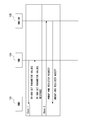
- FIG. 2 shows a part of a message signal between functional elements related to this embodiment together with an arrow indicating the direction thereof.
- Reference numeral 108 denotes a message signal for setting the OMA-DM server 106 as a notification destination when detecting a change in the area of the UE 103 from the HMS 104 to the HNB 102 in accordance with a SET PARAMETER VALUES command conforming to TR-069.
- the signal 108 is transmitted as part of CN Level Parameters defined in 3GPP TS 25.467.
- the signal 108 is transmitted as part of HNB Access Network Related Parameter Types defined in 3GPP TS 32.582.
- the signal 108 is shown as part of the parameters defined in TR-196.
- the signal 108 is referred to as case 1.
- the 109 is a message signal for setting the OMA-DM server 106 from the HNB-GW 105 to the HNB 101 as a notification destination when a change in the area of the UE 103 is detected among the parameters of the standard protocol.
- the signal 109 is transmitted as part of the HUB REGISTER ACCEPT defined in 3GPP S25.469.
- the signal 109 is referred to as case 2.
- a message signal 110 is transmitted from the HNB 102 to the HMS 104 in accordance with the INFORM command in conformity with TR-069 in order to send a notification to the OMA-DM server 106 when a change in the area of the UE 103 is detected.
- 111 is a message signal that the HMS 104 sends to the OMA-DM server 106 a notification that the UE 103 has detected a change in the area of the UE 103 received from the HNB 102 by HTTP.
- Reference numeral 112 denotes a message signal for the HNB 101 to directly send a notification to the OMA-DM server 106 by HTTP when a change in the area of the UE 103 is detected.
- notification by signals 110 and 111 is referred to as case 1
- notification by signal 112 is referred to as case 2.
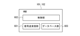
- HNBs 101 and 102 are TR-069 / SOAP / HTTP, HNBAP (HNB Application Part), RUA (RANAP (RANAP ()) with other devices (HMS, OMA-DM server, HNB-GW, etc.).
- Radio Access Network Application Part A signal transmission / reception unit 601 that performs transmission / reception of a signal such as a user application protocol.
- the HNBs 101 and 102 have a control unit 602 that monitors the target IMSI on the data model and determines to notify the HNB-GW 105 or the HMS 104.
- the HNBs 101 and 102 have a database unit 603 for the HNBs 101 and 102 to manage the mobility of the UE 103 and the like.
- the function of each component of the HNBs 101 and 102 may be realized by hardware, or by software realized by a CPU (Central Processing Unit) executing a program while using a memory. There may be.
- CPU Central Processing Unit
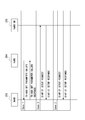
- FIG. 4 is a diagram illustrating a configuration example of the database unit 603 in FIG. Here, only data essential for realizing the characteristic part of the present embodiment is shown, and other data related to the control of the user terminal is omitted.
- 603a is an area for storing a notification destination that is set by the received message and that is notified when a change in the area is detected.
- An area 603b stores a monitoring list (Monitored ⁇ ⁇ ⁇ IMSI List), which is a list of user terminals to be monitored by the HNBs 101 and 102, set by the received message.
- Reference numeral 603c denotes an area for storing a non-monitoring list (NOT Monitored IMSI List), which is a list of user terminals that are not monitored by the HNBs 101 and 102, set by the message received as monitoring information.
- Reference numeral 603d denotes an area for storing a history in which the HNBs 101 and 102 have instructed the OMA-DM server 106 to restrict or add the function of the user terminal, and to restrict or add services to other service servers.
- Example of processing procedure of HNB 101, 102 show a flowchart of an example of the processing procedure of the HNBs 101 and 102. As described above, also in this flowchart, only relevant portions for realizing the characteristic portions of the present embodiment are illustrated.
- step S10 the HNB determines whether or not a change in the area has been detected in any user terminal. If the HNB does not detect a change in the area, the process proceeds to step S30.
- step S11 the HNB determines whether the in-zone change is a change from outside the area to the area or a change from the area to the outside area. If the change is from outside the service area to within the service area, the HNB proceeds to step S13 and determines whether the user terminal that has changed in the service area is a monitoring target according to the monitoring list 603b and / or the non-monitoring list 603c. When it is determined that the user terminal that has changed its location is the monitoring target, the HNB reads the notification destination 603a in step S14, and performs a notification process from the HNB to the OMA-DM server 106 in step S15.
- IMSI the identifier
- the notification message includes an identifier (IMSI) of a subscriber who owns a user terminal that has changed in area, an identifier (cell ID) for identifying a femtocell controlled by the HNB, and a group to which the subscriber belongs if necessary.
- CSG_ID Cell Subscriber Group ID
- the HNB performs normal location processing not described in detail here. In the case where the user terminal is not the monitoring target, the location processing is directly performed in step S16. However, as shown in the sequence diagram of FIG. 16, the RUA CONNECT procedure to the HNB-GW 105 is performed. However, it is omitted in FIG. 5A to avoid complication.
- the HNB determines whether the user terminal that has changed in range in step S17 is a monitoring target according to the monitoring list 603b and / or the non-monitoring list 603c. .
- the HNB reads the notification destination 603a in step S18, and in step S19, the notification process from the HNB to the OMA-DM server 106 is performed as in step S15. To do.
- the HNB performs a normal out-of-service transition process not described in detail here.
- step S20 In the case where the user terminal is not the monitoring target, it is illustrated that the out-of-service transition process is performed directly in step S20. However, as shown in the sequence diagram of FIG. 16, the HNB performs the RUA CONNECT procedure to the HNB-GW 105 and the like. However, it is omitted in FIG. 5A to avoid complication.
- step S30 the HNB determines whether or not each message including the notification destination has been received. Note that processing of messages that do not include a communication destination is omitted. If it is reception at the communication destination, the HNB proceeds to step S31 and extracts a notification destination from the reception data included in the message. Next, in step S32, if specified in the message, the HNB extracts information on the monitoring target (non-monitoring target). In step S33, the HNB registers or updates the extracted notification destination and monitoring target (non-monitoring target) information in the areas indicated by 603a to 603c in FIG.
- step S40 the HNB determines whether there is an instruction from the HNB to change the user terminal function of the OMA-DM server 106 or to change the service of another service server (including restriction, addition, and deletion). If it is determined that there is an instruction, the HNB proceeds to step S41 to create data for change. If the other party is the OMA-DM server 106, the HNB creates the next message.
- the message includes an identifier (cell ID) for identifying a femto cell controlled by the HNB, a CSG_ID for identifying a group to which the subscriber belongs, if necessary, an IMSI to be processed, and an action described later with reference to FIG. Including.
- step S42 the HNB reads the notification destination from 603a in FIG. 4, and transmits the creation message to the notification destination that has read the creation message in step S43.
- the HNB performs other processing in step S50.
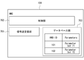
- the HMS 104 includes a signal transmission / reception unit 701 that transmits / receives a signal such as SOAP / HTTP to / from another apparatus (HNB, OMA-DM server, etc.). Further, the HMS 104 has a control unit 702 for adding, deleting, and setting parameters for the HNBs 101 and 102 including, for example, the objects / parameters described in FIG. Further, the HMS 104 has a database unit 703 for managing data for each of the HNBs 101 and 102. The function of each component of the HMS 104 may be realized by hardware, or may be realized by software that is achieved by the CPU executing a program.
- the database unit 703 stores the parameters shown in FIGS. 7 to 9 transmitted by the standard protocols for femtocell control corresponding to the HNBs 101 and 102 maintained and managed by the HMS 104. .
- the database unit 703 of FIG. 6 as an example, Parameter Set 71 for HNB 101 and Parameter Set 72 for HNB 102 are illustrated. Note that it is not necessary for all parameters to be stored for the number of HNBs, and the shared parameters and the parameters depending on each HNB including the notification of the change in the area of the present embodiment may be stored separately.
- Example of notification destination setting data by HMS 104 (Example of notification destination setting data by HMS 104)
- (1) the IMSI to be monitored or not to be monitored shown in FIGS. 7, 8, and 9 is added to TR-196 used in the interface between the HMS and the HNB.
- (2) The host name (FQDN format) and / or IP address information of the notification destination shown in FIGS. 7, 8, and 9 is added to TR-196 used in the interface between the HMS and the HNB. 7 to 9, the addition of the IMSI to be monitored or not monitored, the addition of the host name (FQDN format) of the notification destination, and the IP address information are indicated by bold lines.
- Example 1 CN Level Parameters example
- Monitored IMSI List and Destination Information for mobility related notification parameters are added to CN Level Parameters.
- Example 2 Example of HNB Access Network Related Parameter Types
- Monitored IMSI List and Destination Information for mobility related notification parameters are added to HNB Access Network Related Parameter Types.
- Example 3 Example shown with TR-196 parameters
- FAP Service ⁇ I ⁇ .PresenceMgmt. And FAPService. ⁇ I ⁇ .PresenceMgmt.MemberDetail. ⁇ I ⁇ .
- Objects and parameters are newly added in the femto data model. However, these are only examples and may be added to existing objects and parameters.
- the IMSI to be monitored can be specified, if the following is performed, all the IMSIs can be set as the monitoring targets as the IMSIs to be monitored. 1. Although the FAPService. ⁇ I ⁇ .PresenceMgmt object exists, all are monitored by not setting both Not Monitored List and Monitored List. 2. By setting only the Not monitored List without setting the Monitored List, UEs other than a specific IMSI are monitored. 3. Set Monitored List and do not set Not monitored List. As a result, in the FAPService. ⁇ I ⁇ .PresenceMgmt.MemberDetail. ⁇ I ⁇ . Object that targets a specific IMSI UE, a notification destination IP address or host name can be set for each monitored IMSI. .
- the location change notification destination of this embodiment may be added to the parameters of other groups.
- a transmission protocol, a method, and the like for notification may be added.
- the HNB-GW 105 transmits / receives signals such as SOAP / HTTP and HNBAP, RUA, or RANAP protocol to / from other devices (UE, HNB, HMS, OMA-DM server, etc.).
- a transmission / reception unit 901 is provided.
- the HNB-GW 105 has a control unit 902 that controls routing of signals from the HNB to other functional elements.
- the HNB-GW 105 has a database unit 903 that stores location management information of the UE 103 and the like.
- the HNB-GW 105 may notify the HNBs 101 and 102 of the IMSI information and the notification destination information to be monitored instead of the HMS 104.
- HNBAP 3GPP TS25.469), RUA (3GPP TS25.468), or RANAP (3GPP TS25.413) protocol is used. It should be noted that the function of each component of the HNB-GW 105 may be realized by hardware or may be realized by software that is achieved by the CPU executing a program.
- the database unit 903 stores the parameters of FIG. 11 transmitted in accordance with each standard protocol for femtocell control corresponding to the HNBs 101 and 102 to be connected.
- the database unit 903 in FIG. 10 shows a Parameter Set 91 for the HNB101 and a Parameter Set 92 for the HNB102. Note that all the parameters are not stored as many as the number of HNBs, and the shared parameters and the parameters depending on each HNB including the notification of the change in the area of the present embodiment may be stored separately.
- FIG. 11 shows a case added to the HNBAP HNB REGISTER ACCEPT message.
- the following rules apply: 1. By not setting the Monitored List and not setting the IMSI of the Not monitored List, all are monitored. 2. By setting the IMSI of the Not monitored List without setting the Monitored List, UEs other than the specific IMSI are monitored. 3. Set Monitored List and do not set Not monitored List. As a result, when a specific IMSI UE is to be monitored, and when a specific IMSI UE is to be monitored, a notification destination IP address or host name can be set for each IMSI.
- Another message of HNBAP may be the RUA protocol or the RANAP protocol.
- the HNB directly notifies the server designated by the Destination IP Address or Destination Hostname or the IP-compatible device from the HNB. .
- the OMA-DM server 106 includes a signal transmission / reception unit 801 that transmits / receives signals such as SOAP / HTTP to / from other apparatuses (UE, HNB, HNB-GW, HMS, etc.).
- the OMA-DM server 106 includes a control unit 802 that allows access from the owner of the HNB, accepts setting and changing device control contents, and performs processing.
- the OMA-DM server 106 has a database unit 803 that defines an action to be performed for an event that the UE enters or leaves the HNB range from the HNB, HMS, or HNB-GW.
- the function of each component of the OMA-DM server 106 may be realized by hardware, or may be realized by software achieved by the CPU executing a program.
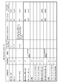
- FIG. 13 shows an example of policy setting on the OMA-DM server 106 side.
- the first row in FIG. 13 is a case of HNB (cell ID is 1000, CSG ID is 10000) installed in a bookstore. If the IMSI other than the store clerk (#A) is monitored as the IMSI, when a UE other than the store clerk (#A) is located in the HNB of the bookstore, the OMA-DM server 106 notifies the camera function of the notified UE. Stop.
- the HNB when a UE other than the clerk (#A) leaves the HNB, the HNB notifies the OMA-DM server 106 that the UE has left the HNB, thereby starting the resumption of the camera function.
- restrictions on the functions of the user terminal are registered in association with the cell ID of each femto cell and further considering CSG_ID and IMSI.
- FIG. 14 is a flowchart illustrating an example of a processing procedure of the OMA-DM server 106.
- FIG. 14 shows only the parts related to the present embodiment, and the conventional processing is omitted.
- step S60 the OMA-DM server 106 determines whether or not a message is received from the HNB or HMS. If the message is not received, the OMA-DM server 106 performs other processing in step S70. If a message has been received, the OMA-DM server 106 proceeds to step S61, and determines whether the message is a notification of a change in location.
- step S62 If it is a notification of a change in the area, the OMA-DM server 106 proceeds to step S62, and reads an action from FIG. 13 based on the above-described cell ID, CSG_ID if necessary, and IMSI to be processed.
- step S63 the OMA-DM server 106 determines whether the in-zone change is a change from outside the area to within the area. If the change is from outside the service area to within the service area, the OMA-DM server 106 proceeds to step S64 and executes an action on the target user terminal that has changed the service area. The execution of such an action is known and will not be described in detail. If there is a change in the area from within the area, the OMA-DM server 106 proceeds to step S65 and cancels the action applied to the target user terminal that has changed the area.
- step S67 the OMA-DM server 106 determines whether or not the received message is an action change (including addition and deletion). If the action is not changed, the OMA-DM server 106 performs other processing in step S80. If the action is to be changed, the OMA-DM server 106 proceeds to step S68 and changes the database corresponding to the cell ID of the femtocell. The received message includes CSG_ID and IMSI to be processed if necessary. Next, in step S69, the OMA-DM server 106 notifies the change completion to the HNB that instructed the change.
- action change including addition and deletion
- the OMA-DM server 106 prepares a database for determining the cell ID of the HNB and performing an appropriate action, and the mechanism that the owner of the HNB can easily change by accessing the Internet or the like. Is building.
- Case 1 example of setting sequence for notification of location change
- Case 2 example of setting sequence for notification of location change
- the HMS 104 sets a monitoring target list (IMSI list) and a notification destination parameter from the HMS 104.
- IMSI list monitoring target list
- the HNB 101 regulates the access of the UE 103 and activates the HNBAP: UE REGISTER procedure (3GPP TS25.469) for the HNB-GW 105 in order to register with the HNB-GW 105.
- the HNB 101 confirms whether the IMSI of the UE 103 is the IMSI to be monitored. If it is not the IMSI to be monitored, the HNB 101 activates the RUA: CONNECT procedure in order to transmit the message received from the UE 103 to the CN 107. If the IMSI is a monitoring target, the HNB 101 notifies the destination IP address or the host name notified that the UE 103 is in the service area.
- the HNB 101 activates the TR-069 INFORMATION method to the HMS 104.
- the HNB 101 notifies the IMSI of the UE 103, the cell ID of the HNB 101, and the CSG ID.
- the HMS 104 further notifies the OMA-DM server 106 of the IMSI of the UE 103, the cell ID of the HNB, and the CSG ID using the POST method or the GET method of the HTTP protocol.
- HTTP HyperText Transfer Protocol
- SOAP SOAP
- Case 2 is a case where the destination IP address or host name notified to the HNB 101 in advance is the OMA-DM server 106.
- the HNB 101 notifies the IMSI of the UE 103, the cell ID of the HNB 101, and the CSG ID using the POST method or the GET method of the HTTP protocol.
- HTTP HyperText Transfer Protocol
- SOAP Simple Object Access Protocol
- the OMA-DM server 106 may be notified of the IMSI of the UE, the cell ID of the HNB, and the CSG ID.
- the OMA-DM server 106 determines an action to be operated from the database information using the UE IMSI, the HNB cell ID, and the CSG ID as keys.
- the third embodiment is an example of a communication system in which the configuration of the communication system of the second embodiment is applied to LTE (Long Term Evolution). Therefore, the description of the second embodiment can be referred to for most processes other than the contents described below. Therefore, the description of the overlapping configuration and processing is omitted.
- LTE Long Term Evolution
- a HeNB (Home evolved NodeB) 201 indicates a small-sized base station corresponding to a radio scheme (OFDMA) defined by LTE (Long Term Evolution).
- a HeMS (Home eNodeB Management System) 104 is a maintenance management server for controlling the HeNB 201.
- the HeNB 201 is connected to a HeNB-GW (Home eNodeB Gateway), and communicates with an Evolved Packet Core (EPC) 207 side developed via the HeNB-GW.
- EPC Evolved Packet Core
- the HeNB-GW 205 is an option in 3GPP standardization (TS36.300). Therefore, communication can be performed directly between the HeNB and the CN using the S1AP (S1 Application Part) protocol (TS36.413) or the like without going through the HeNB-GW 205.
- the HeMS 204 provides the target mobile terminal information (UE information monitored ⁇ by HNB) to be introduced in this embodiment to the HeNBs 201 and 202 using the TR-069 protocol.
- the HeNBs 201 and 202 Based on the monitoring target mobile terminal information, the HeNBs 201 and 202 monitor the UE 203 that enters the HeNB area or the UE 203 that leaves the HeNB 201 and 202.
- the HeNB 201, 202 confirms the monitoring target mobile terminal information when the UE 203 moves within the range of the HeNB 201, 202 or moves away from the range of the HeNB 201, 202.
- the HeNBs 201 and 202 are OMA-DM servers specified by the host name (FQDN format) or IP address specified by the monitoring target mobile terminal information. Notification is made to 206.
- the HeNBs 201 and 202 are identified by the cell ID or the like, and the OMA-DM protocol is activated for the UE 203 in accordance with the action determined as shown in FIG. .
- FIG. 17 illustrates a part of a message signal (transmission data) between functional elements related to the present embodiment together with an arrow indicating the direction thereof.
- Reference numeral 208 denotes a message signal for setting the OMA-DM server 206 as a notification destination when detecting a change in the area of the UE 203 from the HeMS 204 to the HeNB 202 according to the SET PARAMETER VALUES command conforming to TR-069.
- the signal 208 is the same as that described with reference to FIGS. In the sequence of FIG. 19 below, the signal 208 is referred to as case 1.
- the signal 209 is a message signal for setting the OMA-DM server 206 from the HeNB-GW 205 to the HeNBs 201 and 202 as a notification destination when a change in the area of the UE 203 is detected among the parameters of the standard protocol.
- the signal 209 is an S1AP (3GPP TS36.413) S1 SETUP RESPONSE message.
- the signal 209 is referred to as case 2.
- each component The role of each basic component of the third embodiment and the format of each transmission parameter are basically the same as those of the second embodiment, and are therefore omitted to avoid duplication, and are different from the second embodiment. Is described below.
- FIG. 19 shows a setting procedure of UE information to be monitored and notification destination parameters in the case of LTE.
- the HeMS 204 notifies the HeNB 201 of the IMSI list to be monitored by the HeNB and the notification destination parameters defined in advance as in FIG. The same applies to the HeNB 202.
- FIG. 19 shows three types of cases from case 1 to case 3 as a method for setting the notification destination of the change in location.
- Case 3 is a case where the HeNB-GW 205 does not exist, and the HeNB 201 is notified directly from the MME (EPC 207 in FIG. 17) by the S1 SETUP RESPONSE message.
- the HeNB 201 activates the S1AP INITIAL UE MESSAGE procedure to transmit a NAS (Non-Access Stratum) message to the HeNB-GW 205 or the MME (EPC) from the message received from the UE 203. If the IMSI is a monitoring target, the HeNB 201 notifies that the UE 203 is present to the destination IP address or the host name notified in advance.
- NAS Non-Access Stratum
- the IP address or host name of the destination notified in advance is HeMS204.
- the HeNB 201 activates the TR-069 INFORMATION method to the HeMS 204, and notifies the IMSI of the UE, the cell ID of the HeNB, and the CSG ID.
- the HeMS 204 further notifies the OMA-DM server 206 of the IMSI of the UE, the cell ID of the HeNB, and the CSG ID using the POST method or the GET method of the HTTP protocol.
- HTTP Session Initiation Protocol
- Case 2 is a case where the destination IP address or host name notified to the HeNB 201 in advance is the OMA-DM server 206.
- the HeNB 201 notifies the IMSI of the UE 203, the cell ID of the HeNB 201, and the CSG ID using the POST method or the GET method of the HTTP protocol.
- HTTP HyperText Transfer Protocol
- SOAP Simple Object Access Protocol
- the HeNB-GW 205 may identify the IMSI of the UE when receiving INITIAL UE MESSAGE, and notify the OMA-DM server 206 of the IMSI of the UE 203, the HeNB cell ID, and the CSG ID.
- the action to be performed is determined using the database information shown in FIG. 13, as in the W-CDMA case.
- a small base station such as a femtocell detects the UE position. Therefore, not only 3G (FIG. 2) and LTE (FIG. 17) but also Wimax, LTE-Advanced, wireless LAN ( It can be applied to any wireless access system such as Local Area Network. The same applies to wireless systems other than 3G systems and LTE systems. Also, not only small base stations, but also wide coverage base stations with any cell radius such as pico base stations, micro base stations, macro base stations are possible, and furthermore, small base stations are not fixed. It can also be applied to mobile base stations that can be mounted on buses, trains, and bullet trains.
- the macro cell when detecting that a UE is located in a macro cell installed on a roadway such as an expressway or a general road, the macro cell notifies the OMA-DM server and forcibly shifts the mobile phone mode to the drive mode. It becomes possible to make it.
- the drive mode when an incoming call arrives, voice guidance is played and the situation can be communicated to the calling party. As a result, it is possible to suppress the occurrence of accidents by suppressing incoming calls to the user.
- the OMA-DM server is notified that the UE has moved into the HNB or moved away from the HNB, but the notification destination is not limited to the OMA-DM server.
- a server, an application server, or a WEB server may be used. This makes it possible to manage the start and end of service provision by various locations such as information transmission and coupon transmission by utilizing the locality of the femtocell.
- the notification destination may notify an IP compatible device in the home or company. For example, if a user with a mobile phone enters the living room by an HNB in the living room notifying that the UE is located in the femtocell to a home IP compatible device (wireless LAN router, TV, game machine, etc.) The TV can be automatically turned on. Conversely, when a user with a mobile phone comes out of the living room, the TV can be automatically turned off.
- the policy on the OMA-DM server side shown in FIG. 13 is that the HNB owner performs authentication such as HTTP digest authentication with the OMA-DM server side, and if the authentication is OK, via the WEB interface. Access rights that can be freely changed are given.
- the HNB owner can change the database on the OMA-DM server side shown in FIG. FIG. 13 shows a case where the UE to be monitored is located in the HNB.
- the HNB checks the IMSI of the UE. If the UE is the monitoring target IMSI, the event is addressed to the specified IP address or host name. Send to.
- the HNB does not receive the periodic location registration message from the UE, and therefore it can be detected that the UE is separated from the HNB.
- the HNB notifies the specified IP address or host name that the UE has left the HNB.
- the OMA-DM server operates an action according to a policy designated in advance in the database.
- HNB may perform paging etc. regularly with respect to UE, and may confirm that UE is located.
- the HNB when a user in communication moves out of the HNB range by handover, the HNB notifies the specified IP address or host name that the UE has left the HNB after the handover is completed.
- the OMA-DM server operates an action according to a policy designated in advance in the database.
- HNB may perform paging etc. regularly with respect to UE, and may confirm that UE is located.
- the HNBAP protocol used at the interface between the HNB-GW and the HNB includes the IMSI that is monitored or not monitored, the IP address of the notification destination, and the host name (FQDN format) shown in FIG. Add
- the monitored or unmonitored IMSI, the IP address of the notification destination, and the host name (FQDN format) shown in Fig. 18 are added to the S1AP protocol used in the interface between HeNB-GW and HeNB. To do.
- the OMA-DM server is notified and the device control is performed, and after the UE IMSI is determined by the HeNB as shown in FIG. It has a procedure for notifying the DM server and performing device control.
- An automatic device control service based on a location trigger which is obtained by device control using OMA-DM utilizing the locality of femtocells.
- the policy setting method in the OMA-DM server and the policy change by the HNB owner can be performed.
- the above can also be applied to radio systems other than 3G / LTE, and can also be applied to picocells, microcells, and macrocells other than femtocells, and the cells may belong to mobile base stations.
- the notification destination may be a WEB server other than the OMA-DM server, an application server, or an IP compatible device.
- the HMS notifies the HNB of the information to be monitored or not monitored, the UE information that is not monitored, the host name (FQDN format) of the notification destination, or the IP address information by the HNBAP procedure. . Therefore, the HNB can know the monitoring target or non-monitoring UE information, the notification destination host name (FQDN format), or the IP address information. Therefore, when the UE is in the area under the HNB or moves out of the area under the HNB, the event can be notified to an appropriate notification destination (such as an OMA-DM server or an IP compatible device).
- an appropriate notification destination such as an OMA-DM server or an IP compatible device.
- the present embodiment is not limited to the wireless system and the cell radius, and can be applied to a specific macro cell. Therefore, the drive mode in the macro cell installed on the roadway such as an expressway or a general road can be changed. Automatic transition is possible.
- the notification destination may notify the IP compatible device in the home or company. For example, if a user with a mobile phone enters the living room by an HNB in the living room notifying that the UE is located in the femtocell to a home IP compatible device (wireless LAN router, TV, game machine, etc.) The TV can be automatically turned on. Conversely, when a user with a mobile phone comes out of the living room, the TV can be automatically turned off.
- a home IP compatible device wireless LAN router, TV, game machine, etc.
- the HNB owner decides how to control the device. it can.
- the maintenance management server of the RNC in W-CDMA and the eNodeB in LTE can provide the IMSI to be monitored and the information of the notification destination using a protocol such as CORBA (Common Object Request Request Broker Architecture) or SOAP.
- CORBA Common Object Request Request Broker Architecture
- SOAP SOAP
- the present invention may be applied to a system composed of a plurality of devices, or may be applied to a single device. Furthermore, the present invention can also be applied to a case where an information processing program that implements the functions of the embodiments is supplied directly or remotely to a system or apparatus. Therefore, in order to realize the functions of the present invention by a computer, a control program installed in the computer, a medium storing the control program, and a WWW server that downloads the control program are also included in the scope of the present invention.
- the control program can be stored using various types of non-transitory computer readable media and supplied to the computer.
- the non-transitory computer readable medium includes various types of tangible storage media (tangible storage medium).
- Examples of non-transitory computer-readable media include magnetic recording media (eg, flexible disks, magnetic tapes, hard disk drives), magneto-optical recording media (eg, magneto-optical disks), CD-ROMs (Read Only Memory), CD- R, CD-R / W, semiconductor memory (for example, mask ROM, PROM (Programmable ROM), EPROM (Erasable ROM), flash ROM, RAM (Random Access Memory)).
- the control program may be supplied to the computer by various types of transitory computer readable media. Examples of transitory computer readable media include electrical signals, optical signals, and electromagnetic waves.
- the temporary computer-readable medium can supply the program to the computer via a wired communication path such as an electric wire and an optical fiber, or a wireless communication path.
- Appendix 1 A communication system including a femto base station providing a femto cell, A notification destination setting means for setting a notification destination to be notified of a change in the area of the user terminal to the femtocell in the femto base station; When the femto base station detects a change in the area of a user terminal, the femto base station notifies the set notification destination of the change in the area.
- Appendix 2 The communication system according to appendix 1, wherein the notification destination is included in transmission data to the femto base station that conforms to a standard protocol of the communication system that provides a femto cell.
- the notification destination is included in a parameter set by a maintenance management server that manages the femto base station, a parameter set by a gateway connected to the core network, or a parameter set by the packet core via the network.
- the communication system according to Supplementary Note 2. (Appendix 4)
- the notification destination setting means further sets monitoring information in the femto base station indicating whether each user terminal needs to be monitored by the femto base station, When the femto base station detects a change in the area of the user terminal and the monitoring information indicates that monitoring by the femto base station is necessary, the femto base station sets the change in area to the notification destination.
- the notification destination is an information processing apparatus capable of controlling the function of the user terminal,
- the information processing apparatus stores in advance in association with a cell ID for identifying a femto cell controlled by the femto base station that has notified the change in the area when the user terminal is notified of a change from outside the area to the area. Further, the function of the user terminal is restricted or added, and the function restriction or addition of the user terminal is released when a change from the user terminal to the outside of the user terminal is notified. 5.
- the communication system according to any one of 4.
- the information processing apparatus stores restriction or addition of the function of the user terminal in association with an IMSI that identifies a subscriber who owns the user terminal and / or a CSG_ID that identifies a group to which the subscriber belongs.
- the notification destination is an information processing apparatus capable of controlling service provision to a user,
- the information processing apparatus stores in advance in association with a cell ID for identifying a femto cell controlled by the femto base station that has notified the change in the area when the user terminal is notified of a change from outside the area to the area.
- An information processing apparatus that manages user terminals in a communication system that provides femtocells, Storage means for storing at least a function ID of the user terminal in association with a cell ID for identifying a femtocell; Receiving means for receiving from the femto base station that has detected a change in the area of the user terminal with respect to the femto cell, the change in the area notified to the notification destination representing the information processing apparatus preset in the femto base station; If a change from outside the service area of the user terminal to the service area is received, the function of the user terminal stored in the storage unit is limited or added, and if a change from the service area of the user terminal to the service area is received.
- An information processing apparatus comprising: management means for releasing restriction or addition of the function of the user terminal.
- the limitation or addition of the function of the user terminal is further stored in association with the IMSI for identifying the subscriber who owns the user terminal and / or the CSG_ID for identifying the group to which the subscriber belongs.
- (Appendix 12) Means for receiving from the femto base station an instruction to change, add, or delete the restriction or addition of the function of the user terminal stored in the storage means; According to appendix 10 or 11, wherein the storage means changes, adds, or deletes the restriction or addition of the function of the user terminal to the femtocell controlled by the femto base station based on the received instruction.
- An information processing apparatus control method for managing user terminals in a communication system providing femtocells A reception step of receiving the change in the area notified from the femto base station that has detected the change in the area of the user terminal to the femto cell, to the notification destination representing the information processing apparatus preset in the femto base station; If a change from the out-of-service area of the user terminal to the service area is received, the function of the user terminal stored in the storage means is limited or added in association with at least the cell ID for identifying the femto cell, and the user terminal's service area And a management step of releasing restriction or addition of the function of the user terminal when a change from the service area to the service area is received.
- An information processing apparatus that manages services to users in a communication system that provides femtocells, Storage means for storing a service for a user in association with at least a cell ID for identifying a femtocell; Receiving means for receiving from the femto base station that has detected a change in the area of the user terminal to the femto cell, the change in the area notified to the notification destination representing the information processing apparatus preset in the femto base station; If a change from outside the service area of the user terminal to the service area is received, a service for the user stored in the storage unit is started. If a change from the service area of the user terminal to the service area is received, the service to the user is received.
- An information processing apparatus comprising management means for canceling a service.
- (Appendix 16) An information transmission method for transmitting information to a femto base station that controls a femto cell, A notification destination to be notified of a change in the area of the user terminal with respect to the femtocell, As part of the transmitted data that conforms to the standard protocol, An information transmission method comprising transmitting to the femto base station.
- a femto base station for controlling a user terminal in the femtocell in a communication system providing a femtocell, Receiving means for receiving a notification destination to be notified of a change in the area of the user terminal with respect to the femtocell; A femto base station comprising: notification means for notifying the notification destination that has received the change in area when a change in the area of the user terminal is detected.
- Appendix 18 18. The femto base station according to appendix 17, wherein the notification destination is included in transmission data to the femto base station that complies with a standard protocol of a communication system that provides a femto cell.
- the notification destination is included in a parameter set by a maintenance management server that manages the femto base station, a parameter set by a gateway connected to the core network, or a parameter set by the packet core via the network.
- the femto base station according to appendix 18.
- the receiving means further receives monitoring information indicating whether or not each user terminal needs to be monitored by the femto base station,
- the notifying means has received the change in the area when the femto base station detects a change in the area of the user terminal and the monitoring information indicates that monitoring by the femto base station is necessary.
- the femto base station according to appendix 17 characterized in that a notification destination is notified.
- the femto base station When the notification destination is an information processing device that manages user terminals, The femto base station according to appendix 17 or 20, further comprising: a transmission unit that transmits an instruction to change, add, or delete the restriction or addition of the function of the user terminal to the information processing apparatus.
Landscapes
- Engineering & Computer Science (AREA)
- Computer Networks & Wireless Communication (AREA)
- Signal Processing (AREA)
- Computer Security & Cryptography (AREA)
- Databases & Information Systems (AREA)
- Mobile Radio Communication Systems (AREA)
- Telephonic Communication Services (AREA)
Abstract
Description
本発明の第1実施形態としての通信システムについて、図1を用いて説明する。図1は、ユーザ端末(UE(User Equipment))の在圏変化をフェムト基地局(HNB,HeNB)が設定された通知先に通知する通信システムの構成例を示している。図1において、本通信システムはフェムトセルを提供するフェムト基地局10を含み、フェムトセルに対するユーザ端末30の在圏変化を通知すべき通知先を、フェムト基地局10に設定する通知先設定部20を有する。フェムト基地局10は、ユーザ端末30の在圏変化を検知した場合に、設定された通知先に在圏変化を通知する。ここで、在圏変化とは、ユーザ端末30が移動してフェムト基地局10が制御するフェムトセルの圏外から圏内に変化した場合、及び、ユーザ端末30が移動してフェムト基地局10が制御するフェムトセルの圏内から圏外に変化した場合を含んでいる。かかる構成により、フェムト基地局は、ユーザ端末の在圏変化を予め指定された通知先へ通知するのではなく、設定された所望の通知先へ送信することができる。したがって、ユーザ端末の制御変更ができる送信先を選択すれば在圏変化に応じてフェムトセル内でのユーザ端末の制御変更を行なうことができる。従って、本実施形態は、フェムト基地局10への情報送信方法としての特徴も有している。
本実施形態は、フェムトセルを構成する通信システムにおいて、フェムトセルにTR-069ベースにより、予め、報告させておきたいIMSI(International Mobile Subscriber Identity)のリスト及び報告先のOMA-DMサーバのホストネーム(FQDN(Fully Qualified Domain Name)形式)あるいは、IP(Internet Protocol)アドレス情報を登録しておく。そして、フェムトセルにUEが在圏あるいはフェムトセルより離れた場合に、指定されたホストネーム(FQDN形式)、あるいはIPアドレスのOMA-DMサーバに通知を行う。これにより、OMA-DMサーバは、予め定められたポリシーに従い、移動端末に対して、OMA-DMプロトコルにより、デバイス制御可能としたことを特徴としている。
(フェムトセル)
フェムトセルは通常、数十メートルの半径をレンジとする小型基地局である。ユースケースとしては、家庭内あるいは企業内に設置することが想定される。主に、フェムトセルは、(1)カバーレッジの向上、(2)スループットの増加、(3)データオフロード機能により、移動体事業者内のトラフィックを減らし、OPEX(Operating Expense)を下げる、(4)フェムトセル使用時の課金を安くすること、を狙いとして設置される。また、フェムトセルのメリットとして、これらの小型基地局にUEが在圏することによって、ユーザの場所を特定することができる。フェムトセル以外に、よく知られた位置推定方法としては、GPS(Global Positioning System)によっても、ユーザの位置を特定することができるが、GPS方式に比べて以下の利点がある。
・GPS測定ではUEの位置測定頻度が多い場合には、バッテリーが懸念される。
・GPSは建物内での衛星の測定感度が懸念される。
・GPSはビル等でのフロア(階)検出が困難である。
このように、フェムトセルによってUEの位置を特定することは、GPSを用いる場合に比べて、上記の利点がある。本実施形態では、フェムトセル、HNBについては、同じ意味を指す同義語として使用されている。
TR-069(Technical Report 069)は、BroadbandフォーラムのCPE-WAN管理プロトコル(CWMP, CPE WAN Management Protocol)の技術仕様である。この技術仕様は、エンドユーザ機器の遠隔管理のためのプロトコルを定義している。TR-069は、SOAP(Simple Object Access Protocol)/HTTP(Hyper Text Transfer Protocol)にもとづく双方向のプロトコルである。従って、CPE(広域ネットワーク(WAN)と顧客のネットワークとを接続する機器)と自動設定サーバ(ACS, Auto Configuration Servers)との通信を規定している。フェムトシステムでは、CPEはHNBあるいは、HeNBに相当し、ACSはHMSあるいはHeMSに相当している。
Broadbandフォーラムによって定義されたフェムトセル用(HNB用 or HeNB)の標準データモデル(Femto Access Point Service Data Model)を定義している。
OMA-DMとは、"open mobile alliance-device management"の略で,モバイル関連のアプリケーションの標準化を進めるOpen Mobile Allianceが策定したデバイス管理機能である。OMA-DMは、データ交換のためにXML(Extensible Markup Language)を使用してデバイス管理を行い、デバイス管理サーバ及びデバイス(管理対象のクライアント)間の通信によって行われる。OMA-DMは、物理インタフェースでは有線(USB(Universal Serial Bus), RS(Recommended Standard)-232)及び無線インタフェース(GSM(Global System for Mobile Communications), W-CDMA(Wideband Code Multiple Access), IrDA(Infrared Data Association) or Bluetooth, LTE等)の両方にて、様々なデータ転送用のプロトコルをサポートしている。通信はWAP(Wireless Application Protocol) Pushあるいは、SMS(Short Message Service)等のようなメソッドを使用して、非同期的にOMA-DMサーバによって、起動される。
(1)フェムトセルの局所性を活かして、フェムトセルに在圏、あるいは、フェムトセルより離れた場合に即座にOMA-DMサーバに通知される。そのため、リアルタイムなデバイス制御(マナーモード/ドライブモードへの切り替え、携帯電話の特定デバイスの許可/禁止)を実現する。
(2)HNBの所有者がインターネット等のWEBアクセスによって、自在にデバイス制御方法を設定することが可能となる。
(3)フェムトセルの局所性を活かした在圏サービスや家庭/企業内のIP対応デバイスとの間の家電連携/機器連携が可能となる。
本発明の第2実施形態としての通信システムの構成について、図2を用いて説明する。
図2において、HNB(3G Home NodeB)101,102はフェムト基地局と呼ばれ、第3世代の無線方式(W-CDMA)に対応した小型用の基地局を示す。HMS(Home NodeB Mnagement System)104は、HNB101,102制御するための保守管理サーバである。HNB101,102は、HNB-GW(3G HNB Gateway)に接続され、HNB-GWを経由してコアネットワーク(CN:Core Network)側と通信を行うゲートウェイである。
図2には、本実施形態に関連する機能要素間のメッセージ信号の一部がその方向を示す矢印と共に図示されている。
108は、UE103の在圏変化を検知した場合のその通知先としてOMA-DMサーバ106を、HMS104からHNB102にTR-069に準拠したSET PARAMETER VALUES命令に従って設定するメッセージ信号である。以下に図7で示す例では、信号108は、3GPP TS25.467に規定されたCN Level Parametersの一部として送信される。図8で示す例では、信号108は、3GPP TS32.582に規定されたHNB Access Network Related Parameter Typesの一部として送信される。図9で示す例は、信号108は、TR-196に規定されたパラメータの一部として示されている。以下の図15のシーケンスでは、信号108は、ケース1として参照される。
110は、UE103の在圏変化を検知した場合にその通知をOMA-DMサーバ106に送るために、TR-069に準拠したINFORM命令に従ってHNB102からHMS104に送信するメッセージ信号である。111は、HMS104が、HNB102から受信したUE103の在圏変化を検知した通知をHTTPでOMA-DMサーバ106に送るメッセージ信号である。112は、UE103の在圏変化を検知した場合にその通知をHNB101が直接HTTPでOMA-DMサーバ106に送るためのメッセージ信号である。以下の図16のシーケンスでは、信号110及び111による通知はケース1として参照され、信号112による通知はケース2として参照される。
図3に示されるように、HNB101,102は、他の装置(HMS,OMA-DMサーバ,HNB-GW等)とのTR-069/SOAP/HTTP及びHNBAP(HNB Application Part),RUA(RANAP(Radio Access Network Application Part) User Application)プロトコル等の信号の送受信を行う信号送受信部601を有している。また、HNB101,102は、データモデル上の対象IMSIを監視し、HNB-GW105あるいはHMS104に通知することを決定する制御部602を有している。また、HNB101,102は、HNB101,102がUE103の移動性の管理等を行うためのデータベース部603を有している。ここで、HNB101,102の各構成要素の機能は、ハードウエアで実現されてもよいし、CPU(Central Processing Unit)がメモリを使用しながらプログラムを実行することで達成されるソフトウェアでの実現であってもよい。
図4は、図3のデータベース部603の構成例を示す図である。ここでは、本実施形態の特徴的部分を実現するために必須のデータのみを示し、ユーザ端末の制御に関連するような他のデータは省略している。
図5A及び図5Bに、HNB101,102の処理手順例のフローチャートを示す。上記のように、このフローチャートにも、本実施形態の特徴的部分を実現するための関連部分のみを図示している。
在圏変化の検知であれば、HNBは、ステップS11に進んで、在圏変化したユーザ端末を所有する加入者の識別子(IMSI)を取得する。ステップS12では、HNBは、在圏変化が圏外から圏内への変化か/圏内から圏外への変化かを判断する。圏外から圏内への変化であれば、HNBは、ステップS13に進んで、在圏変化したユーザ端末が監視対象か否かを、監視リスト603b及び/又は非監視リスト603cに従って判断する。在圏変化したユーザ端末が監視対象であると判断されると、HNBは、ステップS14で通知先603aを読出し、ステップS15で、HNBからOMA-DMサーバ106への通知処理を行なう。
ステップS30では、HNBは、通知先を含む各メッセージを受信したか否かを判断する。なお、通信先を含まないメッセージの処理は省略している。通信先の受信であれば、HNBは、ステップS31に進んで、メッセージに含まれる受信データから通知先を抽出する。次に、ステップS32で、HNBは、メッセージ中に指定があれば、監視対象(非監視対象)の情報を抽出する。ステップS33で、HNBは、抽出した通知先と監視対象(非監視対象)の情報を、図4の603a~603cに示した領域に登録あるいは更新する。
ステップS40では、HNBは、HNBからのOMA-DMサーバ106のユーザ端末機能の変更や他のサービスサーバのサービスの変更(制限、追加、削除を含む)の指示があるか否かを判断する。指示があると判断すれば、HNBは、ステップS41に進んで、変更用のデータを作成する。相手がOMA-DMサーバ106である場合は、HNBは、次のメッセージを作成する。メッセージは、当該HNBが制御するフェムトセルを識別する識別子(セルID)と、必要ならば加入者の所属するグループを識別するCSG_IDと、処理対象のIMSIと、図13を参照して後述するアクションとを含む。ステップS42で、HNBは、図4の603aから通知先を読出し、ステップS43で作成メッセージを読み出した通知先に送信する。
図6に示されるように、HMS104は、他の装置(HNB,OMA-DMサーバ等)とのSOAP/HTTP等の信号の送受信を行う信号送受信部701を有する。また、HMS104は、HNB101,102に対して、たとえば図9に記載されるオブジェクト/パラメータを含めて、オブジェクトの追加、削除、パラメータを設定するための制御部702を有する。また、HMS104は、HNB101,102毎のデータを管理するためのデータベース部703を有している。なお、HMS104の各構成要素の機能は、ハードウエアで実現されてもよいし、CPUがプログラムを実行することで達成されるソフトウェアでの実現であってもよい。
本実施形態では、(1) HMSとHNB間インタフェースで使用されるTR-196に、図7、図8、図9で示される監視対象あるいは監視対象外のIMSIを追加する。また、(2) HMSとHNB間インタフェースで使用されるTR-196に、図7、図8、図9で示される通知先のホストネーム(FQDN形式)および/またはIPアドレス情報の追加をする。なお、図7乃至図9では、上記監視対象あるいは監視対象外のIMSIの追加や、通知先のホストネーム(FQDN形式)、IPアドレス情報の追加を太線で囲って示している。
図7に示すように、Monitored IMSI List and Destination Information for mobility related notificationパラメータを、CN Level Parametersに追加している。
図8に示すように、Monitored IMSI List and Destination Information for mobility related notificationパラメータを、HNB Access Network Related Parameter Typesに追加している。
図9に示すように、フェムトのデータモデルにおいて、新たに、FAP Service.{i}.PresenceMgmt.及びFAPService.{i}.PresenceMgmt.MemberDetail.{i}.オブジェクト及びパラメータを追加している。しかし、これらは一例であり、既存のオブジェクトやパラメータに追加してもよい。
1.FAPService.{i}.PresenceMgmtのオブジェクトは存在するが、Not Monitored List、Monitored Listを両方とも設定しないことによって、全てを監視対象とする。
2.Monitored Listを設定せず、Not monitored Listのみを設定することによって、特定のIMSI以外のUEを監視対象とする。
3.Monitored Listを設定し、Not monitored Listを設定しない。これによって、特定のIMSIのUEを監視対象とするFAPService.{i}.PresenceMgmt.MemberDetail.{i}.オブジェクトでは、監視対象のIMSIごとに通知先のIPアドレスあるいはホストネームを設定することができる。
図10に示されるように、HNB-GW105は、他の装置(UE,HNB,HMS,OMA-DMサーバ等)とのSOAP/HTTP及び、HNBAP、RUAあるいはRANAPプロトコル等の信号の送受信を行う信号送受信部901を有する。また、HNB-GW105は、HNBからの信号を他の機能要素へのルーティングを制御する制御部902を有する。さらに、HNB-GW105は、UE103の位置管理情報等を記憶するデータベース部903を有している。HNB-GW105が、HMS104の代わりに、監視対象のIMSI情報及び通知先情報をHNB101,102に通知してもよい。この場合には、HNBAP(3GPP TS25.469)、RUA(3GPP TS25.468)、あるいはRANAP(3GPP TS25.413)プロトコルを用いる。なお、HNB-GW105の各構成要素の機能は、ハードウエアで実現されてもよいし、CPUがプログラムを実行することで達成されるソフトウェアでの実現であってもよい。
(例1:HNB REGISTER ACCEPTの例)
図11に、HNBAP HNB REGISTER ACCEPTメッセージに追加するケースを示す。この場合には、以下のルールが適用される。
1.Monitored Listを設定せず、かつ、Not monitored ListのIMSIを設定しないことによって、全てを監視対象とする。
2.Monitored Listを設定せず、かつ、Not monitored ListのIMSIを設定することによって、特定のIMSI以外のUEを監視対象とする。
3.Monitored Listを設定し、Not monitored Listを設定しない。これによって、特定のIMSIのUEを監視対象とするまた、特定のIMSIのUEを監視対象とする場合においては、通知先のIPアドレスあるいはホストネームはIMSIごとに設定することができる。HNBAPの他のメッセージでもRUAプロトコル,RANAPプロトコルでもよい。この場合には、HNBは監視対象のIMSIのUEがHNBに在圏あるいはHNBより離れた場合、HNBより、直接、Destination IP AddressあるいはDestination Hostnameで指定されたサーバ、あるいはIP対応デバイスに通知を行う。
図12に示されるように、OMA-DMサーバ106は、他の装置(UE, HNB, HNB-GW, HMS等)とのSOAP/HTTP等の信号の送受信を行う信号送受信部801を有する。また、OMA-DMサーバ106は、HNBの所有者よりのアクセスを許容してデバイス制御内容の設定、変更を受け付け、処理等を行う制御部802を有する。さらに、OMA-DMサーバ106は、HNBあるいは、HMSあるいは、HNB-GWより、UEがHNB圏内に入ったあるいは、HNB圏内より離れたというイベントに対して行うべきアクションを定義するデータベース部803を有する。なお、ここで、OMA-DMサーバ106の各構成要素の機能は、ハードウエアで実現されてもよいし、CPUがプログラムを実行することで達成されるソフトウェアでの実現であってもよい。
データベース部803の一例を図13に示す。図13にOMA-DMサーバ106側のポリシー設定の一例を示す。たとえば、図13の第1行は、本屋に設置されたHNB(セルIDが1000,CSG IDが10000)の場合である。IMSIとして店員(#A)以外のIMSIが監視対象であると、店員(#A)以外のUEが本屋のHNBに在圏した場合に、OMA-DMサーバ106は、通知されたUEのカメラ機能の停止を行う。また、店員(#A)以外のUEがHNBより離れた場合には、HNBはOMA-DMサーバ106に、UEがHNBより離れたことを通知することによって、カメラ機能の再開を起動する。以下、第2行以下には、各フェムトセルのセルIDに対応付けて、更にCSG_IDやIMSIも考慮してユーザ端末の機能の制限が登録されている。
図14は、OMA-DMサーバ106の処理手順例を示すフローチャートである。なお、図14は本実施形態に関連する部分のみを示し、従来の処理などは省略している。
在圏変化の通知であれば、OMA-DMサーバ106は、ステップS62に進んで、上述のセルIDと、必要ならばCSG_IDと、処理対象のIMSIとに基づいて図13からアクションを読出す。次に、ステップS63で、OMA-DMサーバ106は、在圏変化が圏外から圏内への変化か否かを判断する。圏外から圏内への変化であれば、OMA-DMサーバ106は、ステップS64に進んで、在圏変化をした対象のユーザ端末にアクションを実行する。かかるアクションの実行については、既知であるので詳説しない。圏内から圏外の在圏変化であれば、OMA-DMサーバ106は、ステップS65に進んで、在圏変化をした対象のユーザ端末に施したアクションを解除する。
ステップS67で、OMA-DMサーバ106は、受信したメッセージがアクションの変更(追加、削除も含む)であるか否かを判断する。アクション変更でなければ、OMA-DMサーバ106は、ステップS80で他の処理を行なう。アクションの変更であれば、OMA-DMサーバ106は、ステップS68に進んで、フェムトセルのセルIDに対応するデータベースを変更する。受信したメッセージには、必要ならばCSG_ID、処理対象のIMSIも含まれている。次に、ステップS69で、OMA-DMサーバ106は、変更完了を、変更を指示したHNBに通知する。
実際の動作シーケンスを図15及び図16を用いて説明する。本例では、HMS104がHNB101に対して、予め、図9にて定義されたHNBの監視対象のIMSIリスト及び通知先パラメータの通知を行うものとする。HNB102でも同様である。
設定を行う方法として、ケース1とケース2の2種類のケースを図15に示す。
次に、UE103がHNB101配下に移動し、HNB101がOMA-DMサーバ106に通知を行うケースを説明する。通知を行う方法として、ケース1とケース2の2種類のケースを図16に示す。UE103はTS25.467に記載されるように、HNB101配下に移動すると、UE103はHNB101とRRCコネクションの確立を行う。HNB101はUE103のIMSIを識別するために、IDENTITY REQUEST手順を起動する。その後、HNB101はUE103のアクセス規制を行い、HNB-GW105に登録を行うために、HNB-GW105に対しHNBAP:UE REGISTER手順(3GPP TS25.469)を起動する。HNB101は、HNB-GW105への登録が完了した後に、UE103のIMSIが監視対象のIMSIであるかどうかを確認する。監視対象のIMSIでなければ、HNB101は、UE103より受信したメッセージをCN107に送信するためにRUA:CONNECT手順を起動する。監視対象のIMSIであった場合には、HNB101は、予め通知されたあて先のIPアドレス、あるいは、ホストネーム宛に、UE103が在圏したことを通知する。
第3実施形態は、第2実施形態の通信システムの構成をLTE(Long Term Evolution)に適用した通信システムの例である。従って、以下に記載する内容以外のほとんどの処理は、第2実施形態の記載を参照できる。そのため、重複する構成や処理の説明は省略する。
図17では、HeNB(Home evolved NodeB)201はLTE(Long Term Evolution)で定義された無線方式(OFDMA)に対応した、小型用の基地局を示す。HeMS(Home eNodeB Management System)104は、HeNB201を制御するための保守管理サーバである。HeNB201は、HeNB-GW(Home eNodeB Gateway)に接続され、HeNB-GWを経由して発展したパケットコア(EPC:Evolved Packet Core)207側と通信を行う。なお、HeNB-GW205は3GPP標準化上(TS36.300)でオプションとなっている。そのため、HeNB-GW205を経由せずに、直接、HeNBとCN間でS1AP(S1 Application Part)プロトコル(TS36.413)等により、通信を行うことが可能である。
図17には、本実施形態に関連する機能要素間のメッセージ信号(送信データ)の一部がその方向を示す矢印と共に図示されている。
208は、UE203の在圏変化を検知した場合のその通知先としてOMA-DMサーバ206を、HeMS204からHeNB202にTR-069に準拠したSET PARAMETER VALUES命令に従って設定するメッセージ信号である。信号208は、上記図7乃至図9で説明した内容と同様である。以下の図19のシーケンスでは、信号208は、ケース1として参照される。
211は、UE203の在圏変化を検知した場合にその通知をOMA-DMサーバ206に送るために、TR-069に準拠したINFORM命令に従ってHeNB202からHeMS204に送信するメッセージ信号である。212は、HeMS204が、HeNB202から受信したUE203の在圏変化を検知した通知をHTTPでOMA-DMサーバ206に送るメッセージ信号である。213は、UE203の在圏変化を検知した場合にその通知をHeNB201が直接HTTPでOMA-DMサーバ206に送るためのメッセージ信号である。以下の図20のシーケンスでは、信号211及び212による通知はケース1として参照され、信号213による通知はケース2として参照される。
第3実施形態の各基本的な構成要素の役割と、それぞれの送信パラメータのフォーマットは、基本的に第2実施形態と同様であるので重複を避けるため省略し、第2実施形態との相違点を以下に説明する。
(例1:S1 SETUP RESPONSEの例)
図18に、S1AP(3GPP TS36.413) S1 SETUP RESPONSEメッセージに追加するケーを示す。パラメータの使用方法は、第2実施形態での図11のHNBAPプロトコルと同様である。
LTEの場合における監視対象のUE情報、通知先パラメータの設定手順を図19に示す。HeMS204はHeNB201に対して、予め、図9と同様に定義されたHeNBの監視対象のIMSIリスト及び通知先パラメータの通知を行う。HeNB202も同様である。
在圏変化の通知先の設定を行う方法として、ケース1からケース3の3種類のケースを図19に示す。
次に、UE203がHeNB201配下に移動し、HeNB201がOMA-DMサーバ206に通知を行うケースを説明する。通知を行う方法として、ケース1とケース2の2種類のケースを図20に示す。UE203は、TS25.467に記載されるように、HeNB201配下に移動するとHeNB201とRRCコネクションの確立を行う。そして、HeNB201はUE203のIMSIを識別するために、IDENTITY REQUEST手順を起動する。HeNB201は、UE203のIMSIが監視対象のIMSIであるかどうかを確認する。監視対象のIMSIでなければ、HeNB201は、UE203より受信したメッセージをHeNB-GW205、あるいはMME(EPC)にNAS(Non-Access Stratum)メッセージを送信するためにS1AP INITIAL UE MESSAGE手順を起動する。監視対象のIMSIであった場合には、HeNB201は、予め通知されたあて先のIPアドレス、あるいは、ホストネーム宛に、UE203が在圏したことを通知する。
本実施形態は、フェムトセルのような小型基地局がUEの位置を検出するというものであるため、3G(図2)及びLTE(図17)のみではなく、Wimax、LTE-Advanced、無線LAN(Local Area Network)など、どのような無線アクセスシステムにも適用できる。3GシステムやLTEシステム以外の無線システムについても同様に適用することができる。また、小型基地局のみではなく、よりカバーレッジの広い、ピコ基地局、マイクロ基地局、マクロ基地局などどのようなセル半径の基地局でも可能であり、さらに、小型基地局は固定化されず、バスや電車、新幹線などに搭載できる移動基地局にも適用できる。
1.3Gシステムにおいて、HMSとHNB間インタフェースで使用されるフェムトデータモデル(Broadband TR-196)に、図9で示される、監視対象あるいは、監視対象外のIMSI及び、通知先のIPアドレス、ホストネーム(FQDN形式)を追加する。
以上、本発明の実施形態について詳述したが、それぞれの実施形態に含まれる別々の特徴を如何様に組み合わせたシステム又は装置も、本発明の範疇に含まれる。
上記の実施形態の一部又は全部は、以下の付記のようにも記載されうるが、以下には限られない。
フェムトセルを提供するフェムト基地局を含む通信システムであって、
前記フェムトセルに対するユーザ端末の在圏変化を通知すべき通知先を、前記フェムト基地局に設定する通知先設定手段を有し、
前記フェムト基地局は、ユーザ端末の在圏変化を検知した場合に、設定された前記通知先に前記在圏変化を通知することを特徴とする通信システム。
(付記2)
前記通知先は、フェムトセルを提供する前記通信システムの標準プロトコルに準拠した前記フェムト基地局への送信データに含まれることを特徴とする付記1に記載の通信システム。
(付記3)
前記通知先は、前記フェムト基地局を管理する保守管理サーバが設定するパラメータ、又はコアネットワークへ接続するゲートウェイが設定するパラメータ、又はネットワークを介してパケットコアが設定するパラメータに含まれることを特徴とする付記2に記載の通信システム。
(付記4)
前記通知先設定手段は、さらに、各ユーザ端末が前記フェムト基地局による監視が必要か否かを示す監視用情報を前記フェムト基地局に設定し、
前記フェムト基地局は、ユーザ端末の在圏変化を検知し、かつ前記監視用情報が前記フェムト基地局による監視が必要であることを示す場合に、前記在圏変化を設定された前記通知先に通知することを特徴とする付記1に記載の通信システム。
(付記5)
前記通知先は、ユーザ端末の機能を制御可能な情報処理装置であって、
前記情報処理装置は、前記ユーザ端末の圏外から圏内への変化が通知されれば、少なくとも前記在圏変化を通知したフェムト基地局が制御するフェムトセルを識別するセルIDに対応付けて予め記憶された、前記ユーザ端末の機能の制限又は追加をし、前記ユーザ端末の圏内から圏外への変化が通知されれば、前記ユーザ端末の機能の制限又は追加を解除することを特徴とする付記1乃至4のいずれか1項に記載の通信システム。
(付記6)
前記情報処理装置は、前記ユーザ端末の機能の制限又は追加を、さらにユーザ端末を所有する加入者を識別するIMSI及び/又は前記加入者の所属するグループを識別するCSG_IDに対応付けて記憶することを特徴とする付記5に記載の通信システム。
(付記7)
前記通知先は、ユーザに対するサービス提供を制御可能な情報処理装置であって、
前記情報処理装置は、前記ユーザ端末の圏外から圏内への変化が通知されれば、少なくとも前記在圏変化を通知したフェムト基地局が制御するフェムトセルを識別するセルIDに対応付けて予め記憶された、前記ユーザに対するサービス提供を開始し、前記ユーザ端末の圏内から圏外への変化が通知されれば、前記ユーザに対するサービス提供を終了することを特徴とする付記1乃至4のいずれか1項に記載の通信システム。
(付記8)
前記情報処理装置は、ユーザに対する前記サービス提供を、さらに前記ユーザ端末を所有する加入者を識別するIMSI及び/又は前記加入者の所属するグループを識別するCSG_IDに対応付けて記憶することを特徴とする付記7に記載の通信システム。
(付記9)
フェムトセルを提供する通信システムの制御方法であって、
前記フェムトセルに対するユーザ端末の在圏変化を通知すべき通知先を、前記フェムト基地局に設定する通知先設定ステップと、
ユーザ端末の在圏変化を検知した場合に、前記フェムト基地局が設定された前記通知先に前記在圏変化を通知する在圏変化通知ステップとを有することを特徴とする通信システムの制御方法。
(付記10)
フェムトセルを提供する通信システムにおいてユーザ端末を管理する情報処理装置であって、
少なくともフェムトセルを識別するセルIDに対応付けて、ユーザ端末の機能の制限又は追加を記憶する記憶手段と、
ユーザ端末の前記フェムトセルに対する在圏変化を検知したフェムト基地局から、前記フェムト基地局に予め設定された当該情報処理装置を表わす通知先に通知された前記在圏変化を受信する受信手段と、
前記ユーザ端末の圏外から圏内への変化が受信されれば、前記記憶手段に記憶された前記ユーザ端末の機能の制限又は追加をし、前記ユーザ端末の圏内から圏外への変化が受信されれば、前記ユーザ端末の機能の制限又は追加を解除する管理手段とを有することを特徴とする情報処理装置。
(付記11)
前記ユーザ端末の機能の制限又は追加を、さらにユーザ端末を所有する加入者を識別するIMSI及び/又は前記加入者の所属するグループを識別するCSG_IDに対応付けて記憶することを特徴とする付記10に記載の情報処理装置。
(付記12)
フェムト基地局から、前記記憶手段に記憶されたユーザ端末の前記機能の制限又は追加を変更、追加、又は削除する指示を受信する手段をさらに有し、
受信した前記指示に基づいて、前記記憶手段において、前記フェムト基地局が制御するフェムトセルに対するユーザ端末の前記機能の制限又は追加を変更、追加、又は削除することを特徴とする付記10又は11に記載の情報処理装置。
(付記13)
フェムトセルを提供する通信システムにおいてユーザ端末を管理する情報処理装置の制御方法であって、
ユーザ端末の前記フェムトセルに対する在圏変化を検知したフェムト基地局から、前記フェムト基地局に予め設定された当該情報処理装置を表わす通知先に通知された前記在圏変化を受信する受信ステップと、
前記ユーザ端末の圏外から圏内への変化が受信されれば、少なくともフェムトセルを識別するセルIDに対応付けて記憶手段に記憶されたユーザ端末の機能の制限又は追加をし、前記ユーザ端末の圏内から圏外への変化が受信されれば、前記ユーザ端末の機能の制限又は追加を解除する管理ステップとを有することを特徴とする情報処理装置の制御方法。
(付記14)
フェムトセルを提供する通信システムにおいてユーザ端末を管理する情報処理装置の制御プログラムであって、
ユーザ端末の前記フェムトセルに対する在圏変化を検知したフェムト基地局から、前記フェムト基地局に予め設定された当該情報処理装置を表わす通知先に通知された前記在圏変化を受信する受信ステップと、
前記ユーザ端末の圏外から圏内への変化が受信されれば、少なくともフェムトセルを識別するセルIDに対応付けて記憶手段に記憶されたユーザ端末の機能の制限又は追加をし、前記ユーザ端末の圏内から圏外への変化が受信されれば、前記ユーザ端末の機能の制限又は追加を解除する管理ステップとをコンピュータに実行させるための制御プログラム。
(付記15)
フェムトセルを提供する通信システムにおいてユーザへのサービスを管理する情報処理装置であって、
少なくともフェムトセルを識別するセルIDに対応付けて、ユーザに対するサービスを記憶する記憶手段と、
ユーザ端末のフェムトセルに対する在圏変化を検知したフェムト基地局から、前記フェムト基地局に予め設定された当該情報処理装置を表わす通知先に通知された前記在圏変化を受信する受信手段と、
前記ユーザ端末の圏外から圏内への変化が受信されれば、前記記憶手段に記憶された前記ユーザに対するサービスを開始し、前記ユーザ端末の圏内から圏外への変化が受信されれば、前記ユーザに対するサービスを解除する管理手段とを有することを特徴とする情報処理装置。
(付記16)
フェムトセルを制御するフェムト基地局に情報を送信する情報送信方法であって、
前記フェムトセルに対するユーザ端末の在圏変化を通知すべき通知先を、
標準プロトコルに準拠した送信データの一部として、
前記フェムト基地局に送信することを特徴とする情報送信方法。
(付記17)
フェムトセルを提供する通信システムにおける該フェムトセル内のユーザ端末を制御するフェムト基地局であって、
ユーザ端末の前記フェムトセルに対する在圏変化を通知すべき通知先を受信する受信手段と、
前記ユーザ端末の在圏変化を検知した場合に、該在圏変化を受信した前記通知先に通知する通知手段とを有することを特徴とするフェムト基地局。
(付記18)
前記通知先は、フェムトセルを提供する通信システムの標準プロトコルに準拠した前記フェムト基地局への送信データに含まれることを特徴とする付記17に記載のフェムト基地局。
(付記19)
前記通知先は、前記フェムト基地局を管理する保守管理サーバが設定するパラメータ、又はコアネットワークへ接続するゲートウェイが設定するパラメータ、又はネットワークを介してパケットコアが設定するパラメータに含まれることを特徴とする付記18に記載のフェムト基地局。
(付記20)
前記受信手段は、さらに、各ユーザ端末が前記フェムト基地局による監視が必要か否かを示す監視用情報を受信し、
前記通知手段は、前記フェムト基地局がユーザ端末の在圏変化を検知し、かつ前記監視用情報が前記フェムト基地局による監視が必要であることを示す場合に、前記在圏変化を受信した前記通知先に通知することを特徴とする付記17に記載のフェムト基地局。
(付記21)
前記通知先がユーザ端末を管理する情報処理装置である場合に、
前記情報処理装置に対して、前記ユーザ端末の機能の制限又は追加を変更、追加、又は削除する指示を送信する送信手段をさらに有することを特徴とする付記17又は20に記載のフェムト基地局。
(付記22)
フェムトセルを提供する通信システムにおける該フェムトセルを制御するフェムト基地局の制御方法であって、
ユーザ端末の前記フェムトセルに対する在圏変化を通知すべき通知先を受信する受信ステップと、
前記ユーザ端末の在圏変化を検知した場合に、該在圏変化を受信した前記通知先に通知する通知ステップとを有することを特徴とするフェムト基地局の制御方法。
(付記23)
フェムトセルを提供する通信システムにおける該フェムトセルを制御するフェムト基地局の制御プログラムであって、
ユーザ端末の前記フェムトセルに対する在圏変化を通知すべき通知先を受信する受信ステップと、
前記ユーザ端末の在圏変化を検知した場合に、該在圏変化を受信した前記通知先に通知する通知ステップとをコンピュータに実行させるための制御プログラム。
11 在圏変化
12, 603a 通知先
20 通知先設定部
30 ユーザ端末(UE)
71, 72, 91, 92 Parameter Set
101, 102 HNB
103, 203 UE
104 HMS
105 HNB-GW
106, 206 OMA-DMサーバ
107 CN
108~112, 208, 209, 211~213 メッセージ信号
201, 202 HeNB
204 HeMS
205 HeNB-GW
106 OMA-DMサーバ
207 EPC
210 S1 SETUP RESPONSE
601, 701, 801, 901 信号送受信部
602, 702, 802, 902 制御部
603, 703, 803, 903 データベース部
603b 監視リスト
603c 非監視リスト
603d 履歴
Claims (10)
- フェムトセルを提供するフェムト基地局を含む通信システムであって、
前記フェムトセルに対するユーザ端末の在圏変化を通知すべき通知先を、前記フェムト基地局に設定する通知先設定手段を有し、
前記フェムト基地局は、ユーザ端末の在圏変化を検知した場合に、設定された前記通知先に前記在圏変化を通知することを特徴とする通信システム。 - フェムトセルを提供する通信システムの制御方法であって、
前記フェムトセルに対するユーザ端末の在圏変化を通知すべき通知先を、前記フェムト基地局に設定する通知先設定ステップと、
ユーザ端末の在圏変化を検知した場合に、前記フェムト基地局が設定された前記通知先に前記在圏変化を通知する在圏変化通知ステップとを有することを特徴とする通信システムの制御方法。 - フェムトセルを提供する通信システムにおいてユーザ端末を管理する情報処理装置であって、
少なくともフェムトセルを識別するセルIDに対応付けて、ユーザ端末の機能の制限又は追加を記憶する記憶手段と、
ユーザ端末の前記フェムトセルに対する在圏変化を検知したフェムト基地局から、前記フェムト基地局に予め設定された当該情報処理装置を表わす通知先に通知された前記在圏変化を受信する受信手段と、
前記ユーザ端末の圏外から圏内への変化が受信されれば、前記記憶手段に記憶された前記ユーザ端末の機能の制限又は追加をし、前記ユーザ端末の圏内から圏外への変化が受信されれば、前記ユーザ端末の機能の制限又は追加を解除する管理手段とを有することを特徴とする情報処理装置。 - フェムトセルを提供する通信システムにおいてユーザ端末を管理する情報処理装置の制御方法であって、
ユーザ端末の前記フェムトセルに対する在圏変化を検知したフェムト基地局から、前記フェムト基地局に予め設定された当該情報処理装置を表わす通知先に通知された前記在圏変化を受信する受信ステップと、
前記ユーザ端末の圏外から圏内への変化が受信されれば、少なくともフェムトセルを識別するセルIDに対応付けて記憶手段に記憶されたユーザ端末の機能の制限又は追加をし、前記ユーザ端末の圏内から圏外への変化が受信されれば、前記ユーザ端末の機能の制限又は追加を解除する管理ステップとを有することを特徴とする情報処理装置の制御方法。 - フェムトセルを提供する通信システムにおいてユーザ端末を管理する情報処理装置の制御プログラムが格納された非一時的なコンピュータ可読媒体であって、
前記制御プログラムは、
ユーザ端末の前記フェムトセルに対する在圏変化を検知したフェムト基地局から、前記フェムト基地局に予め設定された当該情報処理装置を表わす通知先に通知された前記在圏変化を受信する受信ステップと、
前記ユーザ端末の圏外から圏内への変化が受信されれば、少なくともフェムトセルを識別するセルIDに対応付けて記憶手段に記憶されたユーザ端末の機能の制限又は追加をし、前記ユーザ端末の圏内から圏外への変化が受信されれば、前記ユーザ端末の機能の制限又は追加を解除する管理ステップと、
をコンピュータに実行させる、
非一時的なコンピュータ可読媒体。 - フェムトセルを提供する通信システムにおいてユーザへのサービスを管理する情報処理装置であって、
少なくともフェムトセルを識別するセルIDに対応付けて、ユーザに対するサービスを記憶する記憶手段と、
ユーザ端末のフェムトセルに対する在圏変化を検知したフェムト基地局から、前記フェムト基地局に予め設定された当該情報処理装置を表わす通知先に通知された前記在圏変化を受信する受信手段と、
前記ユーザ端末の圏外から圏内への変化が受信されれば、前記記憶手段に記憶された前記ユーザに対するサービスを開始し、前記ユーザ端末の圏内から圏外への変化が受信されれば、前記ユーザに対するサービスを解除する管理手段とを有することを特徴とする情報処理装置。 - フェムトセルを制御するフェムト基地局に情報を送信する情報送信方法であって、
前記フェムトセルに対するユーザ端末の在圏変化を通知すべき通知先を、
標準プロトコルに準拠した送信データの一部として、
前記フェムト基地局に送信することを特徴とする情報送信方法。 - フェムトセルを提供する通信システムにおける該フェムトセル内のユーザ端末を制御するフェムト基地局であって、
ユーザ端末の前記フェムトセルに対する在圏変化を通知すべき通知先を受信する受信手段と、
前記ユーザ端末の在圏変化を検知した場合に、該在圏変化を受信した前記通知先に通知する通知手段とを有することを特徴とするフェムト基地局。 - フェムトセルを提供する通信システムにおける該フェムトセルを制御するフェムト基地局の制御方法であって、
ユーザ端末の前記フェムトセルに対する在圏変化を通知すべき通知先を受信する受信ステップと、
前記ユーザ端末の在圏変化を検知した場合に、該在圏変化を受信した前記通知先に通知する通知ステップとを有することを特徴とするフェムト基地局の制御方法。 - フェムトセルを提供する通信システムにおける該フェムトセルを制御するフェムト基地局の制御プログラムが格納された非一時的なコンピュータ可読媒体であって、
前記制御プログラムは、
ユーザ端末の前記フェムトセルに対する在圏変化を通知すべき通知先を受信する受信ステップと、
前記ユーザ端末の在圏変化を検知した場合に、該在圏変化を受信した前記通知先に通知する通知ステップと、
をコンピュータに実行させる、
非一時的なコンピュータ可読媒体。
Priority Applications (8)
| Application Number | Priority Date | Filing Date | Title |
|---|---|---|---|
| CN201180041342.2A CN103069884B (zh) | 2010-08-26 | 2011-08-12 | 信息处理设备和毫微微基站 |
| RU2013108266/08A RU2543559C2 (ru) | 2010-08-26 | 2011-08-12 | Система связи, устройство обработки информации и фемто-базовая станция в ней, способ и программа для управления ими и способ передачи информации в фемто-базовую станцию |
| KR1020137004894A KR101503615B1 (ko) | 2010-08-26 | 2011-08-12 | 통신 시스템, 그 통신 시스템에 있어서의 정보 처리 디바이스와 펨토 기지국, 정보 처리 디바이스와 펨토 기지국을 제어하는 방법, 정보 처리 디바이스와 펨토 기지국을 제어하기 위한 프로그램, 및 정보를 펨토 기지국으로 송신하는 방법 |
| EP11819562.7A EP2611237B1 (en) | 2010-08-26 | 2011-08-12 | Communication system comprising a femto base station and an information processing device for controlling user equipment functions |
| JP2012530517A JP5626348B2 (ja) | 2010-08-26 | 2011-08-12 | 通信システム、該通信システムにおける情報処理装置とフェムト基地局並びにその制御方法と制御プログラム、及びフェムト基地局への情報送信方法 |
| BR112013004377-6A BR112013004377A2 (pt) | 2010-08-26 | 2011-08-12 | sistema de comunicação incluíndo uma estação base femto que provê uma femtocélula, método para controlar um sistema de comunicação, dispositivo de processamento de informação, método pata controlar um dispositivo de processamento de informação, mídia legível por computador não-transitória, método de transmissão de informação, estação base femto e método para controlar uma estação base femto |
| US13/817,308 US9237504B2 (en) | 2010-08-26 | 2011-08-12 | Communication system, information processing device and femto base station therein, method and program for controlling the sames, and method of transmitting information to femto base station |
| US14/974,920 US9973996B2 (en) | 2010-08-26 | 2015-12-18 | Communication system, information processing device and femto base station therein, method and program for controlling the same, and method of transmitting information to femto base station |
Applications Claiming Priority (2)
| Application Number | Priority Date | Filing Date | Title |
|---|---|---|---|
| JP2010-189046 | 2010-08-26 | ||
| JP2010189046 | 2010-08-26 |
Related Child Applications (2)
| Application Number | Title | Priority Date | Filing Date |
|---|---|---|---|
| US13/817,308 A-371-Of-International US9237504B2 (en) | 2010-08-26 | 2011-08-12 | Communication system, information processing device and femto base station therein, method and program for controlling the sames, and method of transmitting information to femto base station |
| US14/974,920 Continuation US9973996B2 (en) | 2010-08-26 | 2015-12-18 | Communication system, information processing device and femto base station therein, method and program for controlling the same, and method of transmitting information to femto base station |
Publications (1)
| Publication Number | Publication Date |
|---|---|
| WO2012026086A1 true WO2012026086A1 (ja) | 2012-03-01 |
Family
ID=45723108
Family Applications (1)
| Application Number | Title | Priority Date | Filing Date |
|---|---|---|---|
| PCT/JP2011/004574 Ceased WO2012026086A1 (ja) | 2010-08-26 | 2011-08-12 | 通信システム、該通信システムにおける情報処理装置とフェムト基地局並びにその制御方法と制御プログラム、及びフェムト基地局への情報送信方法 |
Country Status (8)
| Country | Link |
|---|---|
| US (2) | US9237504B2 (ja) |
| EP (1) | EP2611237B1 (ja) |
| JP (1) | JP5626348B2 (ja) |
| KR (1) | KR101503615B1 (ja) |
| CN (1) | CN103069884B (ja) |
| BR (1) | BR112013004377A2 (ja) |
| RU (1) | RU2543559C2 (ja) |
| WO (1) | WO2012026086A1 (ja) |
Cited By (8)
| Publication number | Priority date | Publication date | Assignee | Title |
|---|---|---|---|---|
| JP2013192160A (ja) * | 2012-03-15 | 2013-09-26 | Nippon Telegraph & Telephone West Corp | 携帯端末在圏検知に基づくポート開閉制御方法 |
| JP2015523806A (ja) * | 2012-06-15 | 2015-08-13 | クゥアルコム・インコーポレイテッドQualcomm Incorporated | ベニューでロケーションベースサービスを提供するための方法およびシステム |
| JP2017512009A (ja) * | 2014-02-20 | 2017-04-27 | アイピー.アクセス リミテッド | ネットワーク要素、ワイヤレス通信システム、及びこれらのための方法 |
| CN107071524A (zh) * | 2016-12-29 | 2017-08-18 | 江苏省广电有线信息网络股份有限公司 | 智能终端管理方法 |
| US9912662B2 (en) | 2012-06-15 | 2018-03-06 | Qualcomm Incorporated | Indoor location server provision and discovery |
| JP2018125858A (ja) * | 2012-11-29 | 2018-08-09 | 日本電気株式会社 | コアネットワーク装置及び端末装置 |
| US10419890B2 (en) | 2012-06-15 | 2019-09-17 | Qualcomm Incorporated | Client access to mobile location services |
| US11265673B2 (en) | 2012-06-15 | 2022-03-01 | Qualcomm Incorporated | Client access to mobile location services |
Families Citing this family (3)
| Publication number | Priority date | Publication date | Assignee | Title |
|---|---|---|---|---|
| US8843622B1 (en) * | 2011-12-19 | 2014-09-23 | Cisco Technology, Inc. | System and method to contact and maintain status of managed devices |
| KR20130109762A (ko) * | 2012-03-28 | 2013-10-08 | 한국전자통신연구원 | 소형 기지국들을 이용하여 전력을 제어하는 장치 및 방법 |
| EP2989826A4 (en) * | 2014-03-21 | 2017-04-19 | MediaTek Singapore Pte Ltd. | Cell selection and reselection for low cost machine-type communication ue |
Citations (8)
| Publication number | Priority date | Publication date | Assignee | Title |
|---|---|---|---|---|
| JP2006041961A (ja) * | 2004-07-28 | 2006-02-09 | Nec Corp | 通信システム、認証装置、基地局装置、端末装置及びそれらに用いるアクセス制御方法 |
| JP2009049564A (ja) | 2007-08-15 | 2009-03-05 | Ntt Docomo Inc | 端末制御システム、端末制御方法、携帯端末および端末制御サーバ |
| JP2009182620A (ja) * | 2008-01-30 | 2009-08-13 | Kyocera Corp | 移動体通信システムの基地局 |
| JP2009188629A (ja) | 2008-02-05 | 2009-08-20 | Softbank Bb Corp | サービス制御システム、移動局、及びサービス制御方法 |
| JP2010502063A (ja) | 2006-08-21 | 2010-01-21 | テレフオンアクチーボラゲット エル エム エリクソン(パブル) | ユーザ機器性能の選択的制御 |
| JP2010062711A (ja) | 2008-09-02 | 2010-03-18 | Fujitsu Ltd | 基地局装置、制御ノード特定方法 |
| WO2010058841A1 (ja) * | 2008-11-20 | 2010-05-27 | 株式会社エヌ・ティ・ティ・ドコモ | 移動通信方法及び無線基地局 |
| JP2010189046A (ja) | 2009-02-19 | 2010-09-02 | Fresh:Kk | ボトルキャップおよび飲料用ボトル |
Family Cites Families (19)
| Publication number | Priority date | Publication date | Assignee | Title |
|---|---|---|---|---|
| SE9600245L (sv) * | 1996-01-23 | 1996-12-23 | Comviq Gsm Ab | Förfarande för att förtäta ett sändar- och mottagarnät för mobiltelefoni |
| DE19638170C2 (de) * | 1996-09-11 | 1998-09-03 | Siemens Ag | Verfahren zum Absetzen von Notrufen in Schnurlos-Telekommunikationssystemen, insbesondere DECT/GAP-Systemen |
| JP3856253B2 (ja) * | 1997-10-16 | 2006-12-13 | ソニー株式会社 | セルラー無線通信システム及び基地局 |
| US6400956B1 (en) * | 1999-11-15 | 2002-06-04 | Lucent Technologies Inc. | Method and apparatus for a wireless telecommunication system that provides location-based action services |
| US20050064856A1 (en) * | 2003-09-18 | 2005-03-24 | International Business Machines Corporation | Method and apparatus for managing functions in a camera phone |
| US8705521B2 (en) | 2004-03-17 | 2014-04-22 | Qualcomm Incorporated | High data rate interface apparatus and method |
| CN101123785B (zh) * | 2006-08-11 | 2013-01-23 | 华为技术有限公司 | 一种通信系统中管理终端的方法和系统 |
| EP2574102A3 (en) * | 2007-04-30 | 2014-01-15 | InterDigital Technology Corporation | Mobility procedures and differentiated charging in home NODE-BS |
| CN101150821A (zh) * | 2007-10-29 | 2008-03-26 | 深圳华为通信技术有限公司 | 切换移动通信终端情景模式的方法及移动通信终端 |
| JP2009253465A (ja) * | 2008-04-02 | 2009-10-29 | Nec Corp | 無線基地局システム、無線基地局制御装置、携帯サービス規制方法及び携帯端末使用規制方法 |
| US8743776B2 (en) * | 2008-06-12 | 2014-06-03 | At&T Mobility Ii Llc | Point of sales and customer support for femtocell service and equipment |
| CN101730204B (zh) * | 2008-10-29 | 2012-08-29 | 中国移动通信集团公司 | 对定位模块工作状态进行控制的方法及其移动终端 |
| US20100112982A1 (en) * | 2008-11-03 | 2010-05-06 | Qualcomm Incorporated | System and method to perform access control and paging using femto cells |
| EP2194739B1 (en) * | 2008-12-04 | 2015-03-25 | Alcatel Lucent | Conditional provision of location information by a femto cell |
| CN104768194B (zh) * | 2009-02-13 | 2020-12-08 | 三星电子株式会社 | 包括毫微微小区的无线通信系统中的切换方法和装置 |
| JP5287361B2 (ja) * | 2009-03-04 | 2013-09-11 | 日本電気株式会社 | 管理装置、通信システム、制御方法及びプログラム |
| US20100227605A1 (en) * | 2009-03-09 | 2010-09-09 | Aymon Patrick Fournier | Control Of A Remote Mobile Device |
| US20110069673A1 (en) * | 2009-09-21 | 2011-03-24 | Starent Networks, Corp | Local routing of voice calls by a femto gateway |
| US20110263260A1 (en) * | 2009-10-22 | 2011-10-27 | Qualcomm Incorporated | Determining cell reselection parameter for transmission by access point |
-
2011
- 2011-08-12 US US13/817,308 patent/US9237504B2/en active Active
- 2011-08-12 KR KR1020137004894A patent/KR101503615B1/ko not_active Expired - Fee Related
- 2011-08-12 BR BR112013004377-6A patent/BR112013004377A2/pt not_active IP Right Cessation
- 2011-08-12 CN CN201180041342.2A patent/CN103069884B/zh active Active
- 2011-08-12 EP EP11819562.7A patent/EP2611237B1/en active Active
- 2011-08-12 WO PCT/JP2011/004574 patent/WO2012026086A1/ja not_active Ceased
- 2011-08-12 JP JP2012530517A patent/JP5626348B2/ja active Active
- 2011-08-12 RU RU2013108266/08A patent/RU2543559C2/ru not_active IP Right Cessation
-
2015
- 2015-12-18 US US14/974,920 patent/US9973996B2/en active Active
Patent Citations (8)
| Publication number | Priority date | Publication date | Assignee | Title |
|---|---|---|---|---|
| JP2006041961A (ja) * | 2004-07-28 | 2006-02-09 | Nec Corp | 通信システム、認証装置、基地局装置、端末装置及びそれらに用いるアクセス制御方法 |
| JP2010502063A (ja) | 2006-08-21 | 2010-01-21 | テレフオンアクチーボラゲット エル エム エリクソン(パブル) | ユーザ機器性能の選択的制御 |
| JP2009049564A (ja) | 2007-08-15 | 2009-03-05 | Ntt Docomo Inc | 端末制御システム、端末制御方法、携帯端末および端末制御サーバ |
| JP2009182620A (ja) * | 2008-01-30 | 2009-08-13 | Kyocera Corp | 移動体通信システムの基地局 |
| JP2009188629A (ja) | 2008-02-05 | 2009-08-20 | Softbank Bb Corp | サービス制御システム、移動局、及びサービス制御方法 |
| JP2010062711A (ja) | 2008-09-02 | 2010-03-18 | Fujitsu Ltd | 基地局装置、制御ノード特定方法 |
| WO2010058841A1 (ja) * | 2008-11-20 | 2010-05-27 | 株式会社エヌ・ティ・ティ・ドコモ | 移動通信方法及び無線基地局 |
| JP2010189046A (ja) | 2009-02-19 | 2010-09-02 | Fresh:Kk | ボトルキャップおよび飲料用ボトル |
Non-Patent Citations (1)
| Title |
|---|
| See also references of EP2611237A4 |
Cited By (9)
| Publication number | Priority date | Publication date | Assignee | Title |
|---|---|---|---|---|
| JP2013192160A (ja) * | 2012-03-15 | 2013-09-26 | Nippon Telegraph & Telephone West Corp | 携帯端末在圏検知に基づくポート開閉制御方法 |
| JP2015523806A (ja) * | 2012-06-15 | 2015-08-13 | クゥアルコム・インコーポレイテッドQualcomm Incorporated | ベニューでロケーションベースサービスを提供するための方法およびシステム |
| US9912662B2 (en) | 2012-06-15 | 2018-03-06 | Qualcomm Incorporated | Indoor location server provision and discovery |
| US10419890B2 (en) | 2012-06-15 | 2019-09-17 | Qualcomm Incorporated | Client access to mobile location services |
| US11265673B2 (en) | 2012-06-15 | 2022-03-01 | Qualcomm Incorporated | Client access to mobile location services |
| JP2018125858A (ja) * | 2012-11-29 | 2018-08-09 | 日本電気株式会社 | コアネットワーク装置及び端末装置 |
| JP2017512009A (ja) * | 2014-02-20 | 2017-04-27 | アイピー.アクセス リミテッド | ネットワーク要素、ワイヤレス通信システム、及びこれらのための方法 |
| US10433217B2 (en) | 2014-02-20 | 2019-10-01 | Ip.Access Limited | Network elements, wireless communication system and methods therefor |
| CN107071524A (zh) * | 2016-12-29 | 2017-08-18 | 江苏省广电有线信息网络股份有限公司 | 智能终端管理方法 |
Also Published As
| Publication number | Publication date |
|---|---|
| CN103069884B (zh) | 2016-12-07 |
| CN103069884A (zh) | 2013-04-24 |
| BR112013004377A2 (pt) | 2020-11-24 |
| US20160105837A1 (en) | 2016-04-14 |
| EP2611237A1 (en) | 2013-07-03 |
| KR20130042585A (ko) | 2013-04-26 |
| RU2543559C2 (ru) | 2015-03-10 |
| US9973996B2 (en) | 2018-05-15 |
| JPWO2012026086A1 (ja) | 2013-10-28 |
| EP2611237B1 (en) | 2019-05-22 |
| US9237504B2 (en) | 2016-01-12 |
| US20130150050A1 (en) | 2013-06-13 |
| RU2013108266A (ru) | 2014-10-10 |
| JP5626348B2 (ja) | 2014-11-19 |
| EP2611237A4 (en) | 2017-11-01 |
| KR101503615B1 (ko) | 2015-03-18 |
Similar Documents
| Publication | Publication Date | Title |
|---|---|---|
| JP5626348B2 (ja) | 通信システム、該通信システムにおける情報処理装置とフェムト基地局並びにその制御方法と制御プログラム、及びフェムト基地局への情報送信方法 | |
| CN103828428B (zh) | 用于无线电接入网中的切换的邻居选择 | |
| CN105916122B (zh) | 用于混合接入模式家用基站的优选接入 | |
| JP5681289B2 (ja) | マクロセル基地局、通信ネットワークおよびフェムトセル基地局、ならびに休眠モードとアクティブ・モードの間でフェムトセル基地局を切り替える方法 | |
| KR101481421B1 (ko) | 이동 통신 시스템에서 단말의 화이트 리스트 관리 방법 및 장치 | |
| US20140357214A1 (en) | Wireless Social and Safety Network | |
| JP5692551B2 (ja) | 基地局装置、移動管理エンティティ、システム、方法及びコンピュータプログラム | |
| JP5168408B2 (ja) | 基地局装置が中継装置の識別情報をブロードキャストする無線通信システム | |
| KR20110102899A (ko) | 주변의 무선 네트워크로의 가입자들의 이동 | |
| WO2011002370A1 (en) | Access network discovery and selection function, andsf, node distributing closed subscriber group, csg, information | |
| CN102474771B (zh) | 家用节点b网关内的ue重定位接入控制 | |
| JP2015146654A (ja) | 移動元基地局、移動先基地局、移動局、通信方法 | |
| RU2586000C1 (ru) | Межсетевой шлюз, система связи, способ управления межсетевым шлюзом и машиночитаемый носитель для них | |
| JPWO2010122712A1 (ja) | ゲートウェイ装置、通信制御方法及び通信制御プログラム | |
| CN109905298B (zh) | 家庭基站、系统及家庭基站接入网络的方法 | |
| KR101464953B1 (ko) | 기지국에 대한 이동 장비의 연결 처리를 관리하기 위한 방법 및 장비 | |
| WO2012136762A1 (en) | Local network identifier for local internet protocol access | |
| JP5216790B2 (ja) | 移動通信システム、オペレーション装置及び移動通信方法 | |
| JP4937338B2 (ja) | 移動通信システム、ネットワーク装置及び移動通信方法 | |
| KR101551499B1 (ko) | 옥내용 기지국의 QoS 제어 방법 및 그를 위한 이동통신 시스템 | |
| CN102131203A (zh) | 家庭基站非正常退网方法 | |
| KR101403812B1 (ko) | 서비스 제공 방법, 가입자 관리 방법 및 옥내용 기지국 | |
| EP2640157A1 (en) | A femtocell base station and a method of registering a user terminal at a femtocell base station | |
| KR20090132018A (ko) | 가입자 관리 기능을 갖는 옥내용 기지국 및 그의 가입자관리 방법 |
Legal Events
| Date | Code | Title | Description |
|---|---|---|---|
| WWE | Wipo information: entry into national phase |
Ref document number: 201180041342.2 Country of ref document: CN |
|
| 121 | Ep: the epo has been informed by wipo that ep was designated in this application |
Ref document number: 11819562 Country of ref document: EP Kind code of ref document: A1 |
|
| WWE | Wipo information: entry into national phase |
Ref document number: 2011819562 Country of ref document: EP |
|
| WWE | Wipo information: entry into national phase |
Ref document number: 13817308 Country of ref document: US |
|
| ENP | Entry into the national phase |
Ref document number: 2012530517 Country of ref document: JP Kind code of ref document: A |
|
| ENP | Entry into the national phase |
Ref document number: 20137004894 Country of ref document: KR Kind code of ref document: A |
|
| NENP | Non-entry into the national phase |
Ref country code: DE |
|
| ENP | Entry into the national phase |
Ref document number: 2013108266 Country of ref document: RU Kind code of ref document: A |
|
| REG | Reference to national code |
Ref country code: BR Ref legal event code: B01A Ref document number: 112013004377 Country of ref document: BR |
|
| REG | Reference to national code |
Ref country code: BR Ref legal event code: B01E Ref document number: 112013004377 Country of ref document: BR Free format text: APRESENTE A TRADUCAO SIMPLES DA FOLHA DE ROSTO DA CERTIDAO DE DEPOSITO DA PRIORIDADE JP 2010-189046; OU DECLARACAO DE QUE OS DADOS DO PEDIDO INTERNACIONAL ESTAO FIELMENTE CONTIDOS NA PRIORIDADE REIVINDICADA, CONTENDO TODOS OS DADOS IDENTIFICADORES DESTA (TITULARES, NUMERO DE REGISTRO, DATA E TITULO), CONFORME O PARAGRAFO UNICO DO ART. 25 DA RESOLUCAO 77/2013. CABE SALIENTAR NAO FOI POSSIVEL INDIVIDUALIZAR OS TITULARES DA CITADA PRIORIDADE, INFORMACAO NECESSARIA PARA O EXAME DA CESSAO DO DOCUMENTO DE PRIORIDADE. |
|
| ENP | Entry into the national phase |
Ref document number: 112013004377 Country of ref document: BR Kind code of ref document: A2 Effective date: 20130225 |