WO2012026271A1 - シミュレーション装置、プログラム、及び記録媒体 - Google Patents
シミュレーション装置、プログラム、及び記録媒体 Download PDFInfo
- Publication number
- WO2012026271A1 WO2012026271A1 PCT/JP2011/067120 JP2011067120W WO2012026271A1 WO 2012026271 A1 WO2012026271 A1 WO 2012026271A1 JP 2011067120 W JP2011067120 W JP 2011067120W WO 2012026271 A1 WO2012026271 A1 WO 2012026271A1
- Authority
- WO
- WIPO (PCT)
- Prior art keywords
- glass fiber
- screw
- thermoplastic resin
- kneading
- shear stress
- Prior art date
- Legal status (The legal status is an assumption and is not a legal conclusion. Google has not performed a legal analysis and makes no representation as to the accuracy of the status listed.)
- Ceased
Links
Images






Classifications
-
- B—PERFORMING OPERATIONS; TRANSPORTING
- B29—WORKING OF PLASTICS; WORKING OF SUBSTANCES IN A PLASTIC STATE IN GENERAL
- B29C—SHAPING OR JOINING OF PLASTICS; SHAPING OF MATERIAL IN A PLASTIC STATE, NOT OTHERWISE PROVIDED FOR; AFTER-TREATMENT OF THE SHAPED PRODUCTS, e.g. REPAIRING
- B29C48/00—Extrusion moulding, i.e. expressing the moulding material through a die or nozzle which imparts the desired form; Apparatus therefor
- B29C48/25—Component parts, details or accessories; Auxiliary operations
- B29C48/251—Design of extruder parts, e.g. by modelling based on mathematical theories or experiments
- B29C48/2511—Design of extruder parts, e.g. by modelling based on mathematical theories or experiments by modelling material flow, e.g. melt interaction with screw and barrel
-
- B—PERFORMING OPERATIONS; TRANSPORTING
- B29—WORKING OF PLASTICS; WORKING OF SUBSTANCES IN A PLASTIC STATE IN GENERAL
- B29B—PREPARATION OR PRETREATMENT OF THE MATERIAL TO BE SHAPED; MAKING GRANULES OR PREFORMS; RECOVERY OF PLASTICS OR OTHER CONSTITUENTS OF WASTE MATERIAL CONTAINING PLASTICS
- B29B7/00—Mixing; Kneading
- B29B7/30—Mixing; Kneading continuous, with mechanical mixing or kneading devices
- B29B7/34—Mixing; Kneading continuous, with mechanical mixing or kneading devices with movable mixing or kneading devices
- B29B7/38—Mixing; Kneading continuous, with mechanical mixing or kneading devices with movable mixing or kneading devices rotary
- B29B7/46—Mixing; Kneading continuous, with mechanical mixing or kneading devices with movable mixing or kneading devices rotary with more than one shaft
- B29B7/48—Mixing; Kneading continuous, with mechanical mixing or kneading devices with movable mixing or kneading devices rotary with more than one shaft with intermeshing devices, e.g. screws
- B29B7/482—Mixing; Kneading continuous, with mechanical mixing or kneading devices with movable mixing or kneading devices rotary with more than one shaft with intermeshing devices, e.g. screws provided with screw parts in addition to other mixing parts, e.g. paddles, gears, discs
-
- B—PERFORMING OPERATIONS; TRANSPORTING
- B29—WORKING OF PLASTICS; WORKING OF SUBSTANCES IN A PLASTIC STATE IN GENERAL
- B29B—PREPARATION OR PRETREATMENT OF THE MATERIAL TO BE SHAPED; MAKING GRANULES OR PREFORMS; RECOVERY OF PLASTICS OR OTHER CONSTITUENTS OF WASTE MATERIAL CONTAINING PLASTICS
- B29B7/00—Mixing; Kneading
- B29B7/30—Mixing; Kneading continuous, with mechanical mixing or kneading devices
- B29B7/34—Mixing; Kneading continuous, with mechanical mixing or kneading devices with movable mixing or kneading devices
- B29B7/38—Mixing; Kneading continuous, with mechanical mixing or kneading devices with movable mixing or kneading devices rotary
- B29B7/46—Mixing; Kneading continuous, with mechanical mixing or kneading devices with movable mixing or kneading devices rotary with more than one shaft
- B29B7/48—Mixing; Kneading continuous, with mechanical mixing or kneading devices with movable mixing or kneading devices rotary with more than one shaft with intermeshing devices, e.g. screws
- B29B7/482—Mixing; Kneading continuous, with mechanical mixing or kneading devices with movable mixing or kneading devices rotary with more than one shaft with intermeshing devices, e.g. screws provided with screw parts in addition to other mixing parts, e.g. paddles, gears, discs
- B29B7/483—Mixing; Kneading continuous, with mechanical mixing or kneading devices with movable mixing or kneading devices rotary with more than one shaft with intermeshing devices, e.g. screws provided with screw parts in addition to other mixing parts, e.g. paddles, gears, discs the other mixing parts being discs perpendicular to the screw axis
-
- B—PERFORMING OPERATIONS; TRANSPORTING
- B29—WORKING OF PLASTICS; WORKING OF SUBSTANCES IN A PLASTIC STATE IN GENERAL
- B29B—PREPARATION OR PRETREATMENT OF THE MATERIAL TO BE SHAPED; MAKING GRANULES OR PREFORMS; RECOVERY OF PLASTICS OR OTHER CONSTITUENTS OF WASTE MATERIAL CONTAINING PLASTICS
- B29B7/00—Mixing; Kneading
- B29B7/30—Mixing; Kneading continuous, with mechanical mixing or kneading devices
- B29B7/34—Mixing; Kneading continuous, with mechanical mixing or kneading devices with movable mixing or kneading devices
- B29B7/38—Mixing; Kneading continuous, with mechanical mixing or kneading devices with movable mixing or kneading devices rotary
- B29B7/46—Mixing; Kneading continuous, with mechanical mixing or kneading devices with movable mixing or kneading devices rotary with more than one shaft
- B29B7/48—Mixing; Kneading continuous, with mechanical mixing or kneading devices with movable mixing or kneading devices rotary with more than one shaft with intermeshing devices, e.g. screws
- B29B7/488—Parts, e.g. casings, sealings; Accessories, e.g. flow controlling or throttling devices
- B29B7/489—Screws
-
- B—PERFORMING OPERATIONS; TRANSPORTING
- B29—WORKING OF PLASTICS; WORKING OF SUBSTANCES IN A PLASTIC STATE IN GENERAL
- B29B—PREPARATION OR PRETREATMENT OF THE MATERIAL TO BE SHAPED; MAKING GRANULES OR PREFORMS; RECOVERY OF PLASTICS OR OTHER CONSTITUENTS OF WASTE MATERIAL CONTAINING PLASTICS
- B29B7/00—Mixing; Kneading
- B29B7/30—Mixing; Kneading continuous, with mechanical mixing or kneading devices
- B29B7/58—Component parts, details or accessories; Auxiliary operations
- B29B7/72—Measuring, controlling or regulating
-
- B—PERFORMING OPERATIONS; TRANSPORTING
- B29—WORKING OF PLASTICS; WORKING OF SUBSTANCES IN A PLASTIC STATE IN GENERAL
- B29B—PREPARATION OR PRETREATMENT OF THE MATERIAL TO BE SHAPED; MAKING GRANULES OR PREFORMS; RECOVERY OF PLASTICS OR OTHER CONSTITUENTS OF WASTE MATERIAL CONTAINING PLASTICS
- B29B7/00—Mixing; Kneading
- B29B7/30—Mixing; Kneading continuous, with mechanical mixing or kneading devices
- B29B7/58—Component parts, details or accessories; Auxiliary operations
- B29B7/72—Measuring, controlling or regulating
- B29B7/726—Measuring properties of mixture, e.g. temperature or density
-
- B—PERFORMING OPERATIONS; TRANSPORTING
- B29—WORKING OF PLASTICS; WORKING OF SUBSTANCES IN A PLASTIC STATE IN GENERAL
- B29B—PREPARATION OR PRETREATMENT OF THE MATERIAL TO BE SHAPED; MAKING GRANULES OR PREFORMS; RECOVERY OF PLASTICS OR OTHER CONSTITUENTS OF WASTE MATERIAL CONTAINING PLASTICS
- B29B7/00—Mixing; Kneading
- B29B7/30—Mixing; Kneading continuous, with mechanical mixing or kneading devices
- B29B7/58—Component parts, details or accessories; Auxiliary operations
- B29B7/72—Measuring, controlling or regulating
- B29B7/728—Measuring data of the driving system, e.g. torque, speed, power, vibration
-
- B—PERFORMING OPERATIONS; TRANSPORTING
- B29—WORKING OF PLASTICS; WORKING OF SUBSTANCES IN A PLASTIC STATE IN GENERAL
- B29B—PREPARATION OR PRETREATMENT OF THE MATERIAL TO BE SHAPED; MAKING GRANULES OR PREFORMS; RECOVERY OF PLASTICS OR OTHER CONSTITUENTS OF WASTE MATERIAL CONTAINING PLASTICS
- B29B7/00—Mixing; Kneading
- B29B7/80—Component parts, details or accessories; Auxiliary operations
- B29B7/88—Adding charges, i.e. additives
- B29B7/90—Fillers or reinforcements, e.g. fibres
-
- B—PERFORMING OPERATIONS; TRANSPORTING
- B29—WORKING OF PLASTICS; WORKING OF SUBSTANCES IN A PLASTIC STATE IN GENERAL
- B29C—SHAPING OR JOINING OF PLASTICS; SHAPING OF MATERIAL IN A PLASTIC STATE, NOT OTHERWISE PROVIDED FOR; AFTER-TREATMENT OF THE SHAPED PRODUCTS, e.g. REPAIRING
- B29C48/00—Extrusion moulding, i.e. expressing the moulding material through a die or nozzle which imparts the desired form; Apparatus therefor
- B29C48/03—Extrusion moulding, i.e. expressing the moulding material through a die or nozzle which imparts the desired form; Apparatus therefor characterised by the shape of the extruded material at extrusion
- B29C48/04—Particle-shaped
-
- B—PERFORMING OPERATIONS; TRANSPORTING
- B29—WORKING OF PLASTICS; WORKING OF SUBSTANCES IN A PLASTIC STATE IN GENERAL
- B29C—SHAPING OR JOINING OF PLASTICS; SHAPING OF MATERIAL IN A PLASTIC STATE, NOT OTHERWISE PROVIDED FOR; AFTER-TREATMENT OF THE SHAPED PRODUCTS, e.g. REPAIRING
- B29C48/00—Extrusion moulding, i.e. expressing the moulding material through a die or nozzle which imparts the desired form; Apparatus therefor
- B29C48/25—Component parts, details or accessories; Auxiliary operations
- B29C48/285—Feeding the extrusion material to the extruder
- B29C48/286—Raw material dosing
-
- B—PERFORMING OPERATIONS; TRANSPORTING
- B29—WORKING OF PLASTICS; WORKING OF SUBSTANCES IN A PLASTIC STATE IN GENERAL
- B29C—SHAPING OR JOINING OF PLASTICS; SHAPING OF MATERIAL IN A PLASTIC STATE, NOT OTHERWISE PROVIDED FOR; AFTER-TREATMENT OF THE SHAPED PRODUCTS, e.g. REPAIRING
- B29C48/00—Extrusion moulding, i.e. expressing the moulding material through a die or nozzle which imparts the desired form; Apparatus therefor
- B29C48/25—Component parts, details or accessories; Auxiliary operations
- B29C48/36—Means for plasticising or homogenising the moulding material or forcing it through the nozzle or die
- B29C48/395—Means for plasticising or homogenising the moulding material or forcing it through the nozzle or die using screws surrounded by a cooperating barrel, e.g. single screw extruders
- B29C48/40—Means for plasticising or homogenising the moulding material or forcing it through the nozzle or die using screws surrounded by a cooperating barrel, e.g. single screw extruders using two or more parallel screws or at least two parallel non-intermeshing screws, e.g. twin screw extruders
- B29C48/425—Means for plasticising or homogenising the moulding material or forcing it through the nozzle or die using screws surrounded by a cooperating barrel, e.g. single screw extruders using two or more parallel screws or at least two parallel non-intermeshing screws, e.g. twin screw extruders using three or more screws
-
- B—PERFORMING OPERATIONS; TRANSPORTING
- B29—WORKING OF PLASTICS; WORKING OF SUBSTANCES IN A PLASTIC STATE IN GENERAL
- B29C—SHAPING OR JOINING OF PLASTICS; SHAPING OF MATERIAL IN A PLASTIC STATE, NOT OTHERWISE PROVIDED FOR; AFTER-TREATMENT OF THE SHAPED PRODUCTS, e.g. REPAIRING
- B29C48/00—Extrusion moulding, i.e. expressing the moulding material through a die or nozzle which imparts the desired form; Apparatus therefor
- B29C48/25—Component parts, details or accessories; Auxiliary operations
- B29C48/36—Means for plasticising or homogenising the moulding material or forcing it through the nozzle or die
- B29C48/50—Details of extruders
- B29C48/505—Screws
- B29C48/54—Screws with additional forward-feeding elements
-
- B—PERFORMING OPERATIONS; TRANSPORTING
- B29—WORKING OF PLASTICS; WORKING OF SUBSTANCES IN A PLASTIC STATE IN GENERAL
- B29C—SHAPING OR JOINING OF PLASTICS; SHAPING OF MATERIAL IN A PLASTIC STATE, NOT OTHERWISE PROVIDED FOR; AFTER-TREATMENT OF THE SHAPED PRODUCTS, e.g. REPAIRING
- B29C48/00—Extrusion moulding, i.e. expressing the moulding material through a die or nozzle which imparts the desired form; Apparatus therefor
- B29C48/25—Component parts, details or accessories; Auxiliary operations
- B29C48/36—Means for plasticising or homogenising the moulding material or forcing it through the nozzle or die
- B29C48/50—Details of extruders
- B29C48/505—Screws
- B29C48/57—Screws provided with kneading disc-like elements, e.g. with oval-shaped elements
-
- B—PERFORMING OPERATIONS; TRANSPORTING
- B29—WORKING OF PLASTICS; WORKING OF SUBSTANCES IN A PLASTIC STATE IN GENERAL
- B29C—SHAPING OR JOINING OF PLASTICS; SHAPING OF MATERIAL IN A PLASTIC STATE, NOT OTHERWISE PROVIDED FOR; AFTER-TREATMENT OF THE SHAPED PRODUCTS, e.g. REPAIRING
- B29C48/00—Extrusion moulding, i.e. expressing the moulding material through a die or nozzle which imparts the desired form; Apparatus therefor
- B29C48/25—Component parts, details or accessories; Auxiliary operations
- B29C48/36—Means for plasticising or homogenising the moulding material or forcing it through the nozzle or die
- B29C48/50—Details of extruders
- B29C48/505—Screws
- B29C48/585—Screws provided with gears interacting with the flow
-
- B—PERFORMING OPERATIONS; TRANSPORTING
- B29—WORKING OF PLASTICS; WORKING OF SUBSTANCES IN A PLASTIC STATE IN GENERAL
- B29C—SHAPING OR JOINING OF PLASTICS; SHAPING OF MATERIAL IN A PLASTIC STATE, NOT OTHERWISE PROVIDED FOR; AFTER-TREATMENT OF THE SHAPED PRODUCTS, e.g. REPAIRING
- B29C48/00—Extrusion moulding, i.e. expressing the moulding material through a die or nozzle which imparts the desired form; Apparatus therefor
- B29C48/25—Component parts, details or accessories; Auxiliary operations
- B29C48/92—Measuring, controlling or regulating
-
- G—PHYSICS
- G06—COMPUTING OR CALCULATING; COUNTING
- G06F—ELECTRIC DIGITAL DATA PROCESSING
- G06F30/00—Computer-aided design [CAD]
- G06F30/20—Design optimisation, verification or simulation
-
- B—PERFORMING OPERATIONS; TRANSPORTING
- B29—WORKING OF PLASTICS; WORKING OF SUBSTANCES IN A PLASTIC STATE IN GENERAL
- B29B—PREPARATION OR PRETREATMENT OF THE MATERIAL TO BE SHAPED; MAKING GRANULES OR PREFORMS; RECOVERY OF PLASTICS OR OTHER CONSTITUENTS OF WASTE MATERIAL CONTAINING PLASTICS
- B29B9/00—Making granules
- B29B9/02—Making granules by dividing preformed material
- B29B9/06—Making granules by dividing preformed material in the form of filamentary material, e.g. combined with extrusion
-
- B—PERFORMING OPERATIONS; TRANSPORTING
- B29—WORKING OF PLASTICS; WORKING OF SUBSTANCES IN A PLASTIC STATE IN GENERAL
- B29B—PREPARATION OR PRETREATMENT OF THE MATERIAL TO BE SHAPED; MAKING GRANULES OR PREFORMS; RECOVERY OF PLASTICS OR OTHER CONSTITUENTS OF WASTE MATERIAL CONTAINING PLASTICS
- B29B9/00—Making granules
- B29B9/12—Making granules characterised by structure or composition
- B29B9/14—Making granules characterised by structure or composition fibre-reinforced
-
- B—PERFORMING OPERATIONS; TRANSPORTING
- B29—WORKING OF PLASTICS; WORKING OF SUBSTANCES IN A PLASTIC STATE IN GENERAL
- B29C—SHAPING OR JOINING OF PLASTICS; SHAPING OF MATERIAL IN A PLASTIC STATE, NOT OTHERWISE PROVIDED FOR; AFTER-TREATMENT OF THE SHAPED PRODUCTS, e.g. REPAIRING
- B29C2948/00—Indexing scheme relating to extrusion moulding
- B29C2948/92—Measuring, controlling or regulating
- B29C2948/92009—Measured parameter
- B29C2948/92085—Velocity
- B29C2948/92104—Flow or feed rate
-
- B—PERFORMING OPERATIONS; TRANSPORTING
- B29—WORKING OF PLASTICS; WORKING OF SUBSTANCES IN A PLASTIC STATE IN GENERAL
- B29C—SHAPING OR JOINING OF PLASTICS; SHAPING OF MATERIAL IN A PLASTIC STATE, NOT OTHERWISE PROVIDED FOR; AFTER-TREATMENT OF THE SHAPED PRODUCTS, e.g. REPAIRING
- B29C2948/00—Indexing scheme relating to extrusion moulding
- B29C2948/92—Measuring, controlling or regulating
- B29C2948/92009—Measured parameter
- B29C2948/92228—Content, e.g. percentage of humidity, volatiles, contaminants or degassing
-
- B—PERFORMING OPERATIONS; TRANSPORTING
- B29—WORKING OF PLASTICS; WORKING OF SUBSTANCES IN A PLASTIC STATE IN GENERAL
- B29C—SHAPING OR JOINING OF PLASTICS; SHAPING OF MATERIAL IN A PLASTIC STATE, NOT OTHERWISE PROVIDED FOR; AFTER-TREATMENT OF THE SHAPED PRODUCTS, e.g. REPAIRING
- B29C2948/00—Indexing scheme relating to extrusion moulding
- B29C2948/92—Measuring, controlling or regulating
- B29C2948/92323—Location or phase of measurement
- B29C2948/92361—Extrusion unit
- B29C2948/92409—Die; Nozzle zone
-
- B—PERFORMING OPERATIONS; TRANSPORTING
- B29—WORKING OF PLASTICS; WORKING OF SUBSTANCES IN A PLASTIC STATE IN GENERAL
- B29C—SHAPING OR JOINING OF PLASTICS; SHAPING OF MATERIAL IN A PLASTIC STATE, NOT OTHERWISE PROVIDED FOR; AFTER-TREATMENT OF THE SHAPED PRODUCTS, e.g. REPAIRING
- B29C2948/00—Indexing scheme relating to extrusion moulding
- B29C2948/92—Measuring, controlling or regulating
- B29C2948/92504—Controlled parameter
- B29C2948/9258—Velocity
- B29C2948/9259—Angular velocity
-
- B—PERFORMING OPERATIONS; TRANSPORTING
- B29—WORKING OF PLASTICS; WORKING OF SUBSTANCES IN A PLASTIC STATE IN GENERAL
- B29C—SHAPING OR JOINING OF PLASTICS; SHAPING OF MATERIAL IN A PLASTIC STATE, NOT OTHERWISE PROVIDED FOR; AFTER-TREATMENT OF THE SHAPED PRODUCTS, e.g. REPAIRING
- B29C2948/00—Indexing scheme relating to extrusion moulding
- B29C2948/92—Measuring, controlling or regulating
- B29C2948/92504—Controlled parameter
- B29C2948/9258—Velocity
- B29C2948/926—Flow or feed rate
-
- B—PERFORMING OPERATIONS; TRANSPORTING
- B29—WORKING OF PLASTICS; WORKING OF SUBSTANCES IN A PLASTIC STATE IN GENERAL
- B29C—SHAPING OR JOINING OF PLASTICS; SHAPING OF MATERIAL IN A PLASTIC STATE, NOT OTHERWISE PROVIDED FOR; AFTER-TREATMENT OF THE SHAPED PRODUCTS, e.g. REPAIRING
- B29C2948/00—Indexing scheme relating to extrusion moulding
- B29C2948/92—Measuring, controlling or regulating
- B29C2948/92504—Controlled parameter
- B29C2948/92723—Content, e.g. percentage of humidity, volatiles, contaminants or degassing
-
- B—PERFORMING OPERATIONS; TRANSPORTING
- B29—WORKING OF PLASTICS; WORKING OF SUBSTANCES IN A PLASTIC STATE IN GENERAL
- B29C—SHAPING OR JOINING OF PLASTICS; SHAPING OF MATERIAL IN A PLASTIC STATE, NOT OTHERWISE PROVIDED FOR; AFTER-TREATMENT OF THE SHAPED PRODUCTS, e.g. REPAIRING
- B29C2948/00—Indexing scheme relating to extrusion moulding
- B29C2948/92—Measuring, controlling or regulating
- B29C2948/92819—Location or phase of control
- B29C2948/92952—Drive section, e.g. gearbox, motor or drive fluids
-
- B—PERFORMING OPERATIONS; TRANSPORTING
- B29—WORKING OF PLASTICS; WORKING OF SUBSTANCES IN A PLASTIC STATE IN GENERAL
- B29C—SHAPING OR JOINING OF PLASTICS; SHAPING OF MATERIAL IN A PLASTIC STATE, NOT OTHERWISE PROVIDED FOR; AFTER-TREATMENT OF THE SHAPED PRODUCTS, e.g. REPAIRING
- B29C48/00—Extrusion moulding, i.e. expressing the moulding material through a die or nozzle which imparts the desired form; Apparatus therefor
- B29C48/25—Component parts, details or accessories; Auxiliary operations
- B29C48/285—Feeding the extrusion material to the extruder
- B29C48/297—Feeding the extrusion material to the extruder at several locations, e.g. using several hoppers or using a separate additive feeding
-
- B—PERFORMING OPERATIONS; TRANSPORTING
- B29—WORKING OF PLASTICS; WORKING OF SUBSTANCES IN A PLASTIC STATE IN GENERAL
- B29C—SHAPING OR JOINING OF PLASTICS; SHAPING OF MATERIAL IN A PLASTIC STATE, NOT OTHERWISE PROVIDED FOR; AFTER-TREATMENT OF THE SHAPED PRODUCTS, e.g. REPAIRING
- B29C48/00—Extrusion moulding, i.e. expressing the moulding material through a die or nozzle which imparts the desired form; Apparatus therefor
- B29C48/25—Component parts, details or accessories; Auxiliary operations
- B29C48/36—Means for plasticising or homogenising the moulding material or forcing it through the nozzle or die
- B29C48/395—Means for plasticising or homogenising the moulding material or forcing it through the nozzle or die using screws surrounded by a cooperating barrel, e.g. single screw extruders
- B29C48/40—Means for plasticising or homogenising the moulding material or forcing it through the nozzle or die using screws surrounded by a cooperating barrel, e.g. single screw extruders using two or more parallel screws or at least two parallel non-intermeshing screws, e.g. twin screw extruders
- B29C48/402—Means for plasticising or homogenising the moulding material or forcing it through the nozzle or die using screws surrounded by a cooperating barrel, e.g. single screw extruders using two or more parallel screws or at least two parallel non-intermeshing screws, e.g. twin screw extruders the screws having intermeshing parts
-
- B—PERFORMING OPERATIONS; TRANSPORTING
- B29—WORKING OF PLASTICS; WORKING OF SUBSTANCES IN A PLASTIC STATE IN GENERAL
- B29C—SHAPING OR JOINING OF PLASTICS; SHAPING OF MATERIAL IN A PLASTIC STATE, NOT OTHERWISE PROVIDED FOR; AFTER-TREATMENT OF THE SHAPED PRODUCTS, e.g. REPAIRING
- B29C48/00—Extrusion moulding, i.e. expressing the moulding material through a die or nozzle which imparts the desired form; Apparatus therefor
- B29C48/25—Component parts, details or accessories; Auxiliary operations
- B29C48/36—Means for plasticising or homogenising the moulding material or forcing it through the nozzle or die
- B29C48/395—Means for plasticising or homogenising the moulding material or forcing it through the nozzle or die using screws surrounded by a cooperating barrel, e.g. single screw extruders
- B29C48/40—Means for plasticising or homogenising the moulding material or forcing it through the nozzle or die using screws surrounded by a cooperating barrel, e.g. single screw extruders using two or more parallel screws or at least two parallel non-intermeshing screws, e.g. twin screw extruders
- B29C48/405—Intermeshing co-rotating screws
Definitions
- the present invention relates to a simulation apparatus for deriving the manufacturing conditions of thermoplastic resin composition pellets, a program for realizing the function of the simulation apparatus, and a computer-readable recording medium storing the program.
- thermoplastic resin composition pellets As a method for producing glass fiber reinforced thermoplastic resin composition pellets by mixing and kneading glass fibers with a thermoplastic resin, the thermoplastic resin is supplied to an extruder and melted, then the glass fibers are supplied, and the inside of the extruder.
- a method of mixing and kneading a thermoplastic resin and glass fiber and cooling and granulating the mixture is common.
- twin-screw extruder As the extruder, a single-screw extruder and a full-mesh twin-screw extruder in the same direction (hereinafter sometimes referred to as a twin-screw extruder) are used, but compared with a single-screw extruder, a twin-screw extruder is A twin screw extruder is more preferably used because of higher productivity and freedom of operation.
- the glass fiber is a monofilament having a diameter of 6 ⁇ m to 20 ⁇ m, which is a bundle of about 300 to 3000 pieces, wound into a roving, or roving.
- the one cut to a length of 1 to 4 mm (hereinafter sometimes referred to as chopped strand) is used. Since chopped glass is more convenient for handling, when manufacturing glass fiber reinforced thermoplastic resin composition pellets industrially, the thermoplastic resin is supplied to a twin screw extruder and the thermoplastic resin is melted. The most common method is to supply chopped glass from the middle of the twin-screw extruder, mix and knead the molten thermoplastic resin and glass fiber, extrude the mixture, and cool and solidify.
- the productivity of the glass fiber reinforced thermoplastic resin composition pellets using the above twin screw extruder is determined by the plasticizing and mixing and kneading ability of the twin screw extruder.
- the plasticizing ability of the twin screw extruder depends on the groove depth of the screw (the difference between the outer diameter and the valley diameter of the screw), the torque generated by the screw, and the rotational speed.
- a twin screw extruder having a large groove depth, a high torque and a high rotation speed has been developed.
- the plasticizing ability of the twin screw extruder has been dramatically improved.
- the mixing and kneading ability of the twin screw extruder depends on the screw design. With the improvement of the plasticizing ability of the twin-screw extruder, the residence time has decreased, so the development of a screw design having an efficient kneading and mixing performance in a short time is required.
- chopped strands in which 300 to 3000 monofilaments are bundled are generally used as glass fibers. This is because, in the method of supplying glass fibers to a twin-screw extruder without forming a bundle of monofilaments, the monofilament becomes cottony, loses fluidity, and is difficult to handle.
- the chopped strand is mixed and kneaded in a twin-screw extruder until it is fibrillated and becomes a monofilament. At the same time, the chopped strand is broken until the length of the monofilament is 300 ⁇ m to 1000 ⁇ m.
- the monofilament is not defibrated, and a part or all of the chopped strand that is in the state of the monofilament aggregate remains in the resin composition pellets. If some or all of the chopped strands remain in the glass fiber reinforced thermoplastic resin composition pellets, in injection molding, some or all of the chopped strands may be clogged in the gate, making injection molding impossible, or injection molding. Even if it is possible, some or all of the chopped strands are present in the molded product, resulting in poor appearance or reduced function.
- Patent Document 1 In order to improve the productivity of the glass fiber reinforced thermoplastic resin composition pellets and to produce them economically, the high-function twin-screw extruder of Patent Document 1 has been used. When improved, it becomes more difficult to defibrate chopped strands completely into monofilaments in a short residence time, and a technique for defibration into monofilaments while maintaining high productivity is required.
- the present invention has been made in order to solve the above-described problems, and the object thereof is to provide an undefined glass fiber which is an aggregate of monofilaments in the production of a resin molded article using a meshing type biaxial or more extruder. It is an object of the present invention to provide a simulation apparatus for deriving a manufacturing condition capable of opening a bundle into a monofilament, a program for realizing the function of the simulation apparatus, and a computer-readable recording medium storing the program.
- the inventors of the present invention have made extensive studies in order to solve the above problems.
- the physical quantities obtained by numerical analysis are the number N of pellets containing undefined glass fiber bundles (per unit weight). It is found that there is no clear correlation with the number of pellets containing undefined glass fiber bundles) and the smallest value among the time integral values of shear stress applied to each glass fiber bundle derived by the particle tracking method.
- minimum shear stress history value T min is has been found that there is a correlation between the pellets number N containing non-fibrillated glass fiber bundles.
- the shear stress generated in the twin screw extruder is analyzed, and when the ratio (Q / Ns) between the discharge amount Q and the screw rotation speed Ns is constant, the minimum shear stress history value T min is controlled.
- the present inventors have found that the number N of pellets per unit amount including undefined glass fibers can be controlled. Further, even if the ratio (Q / Ns) is not constant, the number N of pellets per unit amount including undefined glass fibers can be expressed by a specific formula using the T min and (Q / Ns). As a result, the present invention has been completed. More specifically, the present invention provides the following.
- the following mathematical formula (I) is derived, and the production conditions calculated by the production condition calculation means for calculating the production conditions where the number N of unfiltrated pellets per unit amount is equal to or less than a predetermined value, and the production conditions calculated by the production condition calculation means Output information, and the information input to the input means is a length L of a screw element disposed in a portion where the thermoplastic resin and the glass fiber bundle are kneaded in the extruder.
- the minimum shear stress history which is the smallest value among the time integral values by performing the time integration of the shear stress received in the extruder after the number N of unfiltrated pellets per unit amount and the glass fiber bundle is supplied to the extruder
- a simulation apparatus including a plurality of sets of values T min . ( ⁇ , ⁇ , and ⁇ in the above formula (I) are constants of 0 or more.)
- the manufacturing condition calculating means for each condition of the plurality of L / D, the approximate curve generating step of generating an approximation curve representing the relationship between the discharge amount Q and the minimum shear stress history value T min, the based on the formula (I), a threshold T min determining step of the threshold T min determined is the minimum shear stress history value T min of non-fibrillation pellets number N is below the predetermined value per volume of the unit, each trendline
- a discharge amount Qn calculation step for calculating each discharge amount (Qn) at the threshold value T min from a relational value derivation step for deriving a relational expression between the L / D and the Qn.
- the simulation apparatus according to (1) or (2), wherein a manufacturing condition is selected based on an expression.
- a program for realizing the function of the simulation apparatus according to any one of (1) to (4) by a computer is a program for realizing the function of the simulation apparatus according to any one of (1) to (4) by a computer.
- the glass fiber bundle is controlled by controlling the minimum value (minimum shear stress history value Tmin ) of the time integral value of the shear stress received by the glass fiber bundle when kneading the glass fiber bundle and the thermoplastic resin. Manufacturing conditions under which the bundle is defibrated into monofilaments can be derived by simulation.
- the present invention can solve the above-mentioned problem of undefining glass fibers even when such a high-performance twin-screw extruder is used.
- FIG. 1 is a diagram illustrating an example of a screw configuration of an extruder.
- FIG. 2 is a block diagram showing an example of the simulation apparatus of the present invention.
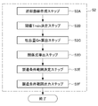
- FIG. 3 is a flowchart illustrating an example of the simulation method.
- FIG. 4 is a flowchart showing an example of a simulation method when changing the extruder size.
- FIG. 5 is a flowchart showing an example of a simulation method in which S2 is different from the flowchart shown in FIG.
- Figure 6 is a diagram showing an approximation curve representing the relationship between the discharge amount Q and minimum shear stress history value T min for each (L / D).
- FIG. 1 is a diagram illustrating an example of a screw configuration of an extruder.
- FIG. 2 is a block diagram showing an example of the simulation apparatus of the present invention.
- FIG. 3 is a flowchart illustrating an example of the simulation method.
- FIG. 4 is a flowchart showing an example of a simulation method when changing the ex
- FIG. 8 is a diagram showing a specific screw pattern used in the example.
- FIG. 9 is a diagram showing a specific screw shape used in the example.
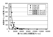
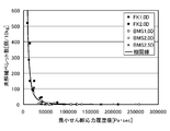
- FIG. 12 shows the minimum shear stress history value (Pa ⁇ sec) that hardly depends on the Q / Ns of the extruder used in the examples, and the number of pellets in which part or all of the glass fiber bundle is not defibrated (pieces / 10 kg of pellets). It is a figure which shows the relationship (correlation line) with this.
- FIG. 13 is a diagram showing the relationship between the discharge amount of the extruder used in the examples and the minimum shear stress history value.
- FIG. 14 is a diagram showing the relationship between the discharge amount of the extruder used in the
- the simulation apparatus of the present invention derives the production conditions for producing glass fiber reinforced thermoplastic resin composition pellets by simulation. Before describing the simulation apparatus of the present invention, first, a method for producing a glass fiber reinforced thermoplastic resin composition pellet will be briefly described.
- the method for producing glass fiber reinforced thermoplastic resin composition pellets is a method for producing glass fiber reinforced thermoplastic resin composition pellets using a biaxial or more extruder equipped with screws that rotate and mesh with each other.
- the method for producing glass fiber reinforced thermoplastic resin composition pellets includes the following steps, for example.
- a plasticizing step in which a thermoplastic resin is supplied to the extruder and heated, kneaded and plasticized.
- a kneading step of supplying one or more glass fiber bundles to an extruder after the plasticizing step and kneading the defibrated glass fibers and the plasticized thermoplastic resin while defibrating the glass fiber bundle.
- a pelletizing step of pelletizing the extruded glass fiber reinforced thermoplastic resin composition.
- a twin screw extruder having the screw configuration shown in FIG. 1 is used.
- This extruder includes a resin plasticizing part and a kneading part.
- the resin plasticizing section includes a supply section, a plasticizing section, and a transport section, and the kneading section includes a kneading section 1 and a kneading section 2.
- thermoplastic resin supplied from the hopper is transferred and melted to make a homogeneous melt.
- thermoplastic resin supplied from the hopper becomes a homogeneous melt (details of the plasticizing step).
- thermoplastic resin The kind of thermoplastic resin to be used is not particularly limited. Specific examples of the thermoplastic resin include polypropylene, polyacetal, liquid crystal resin, polybutylene terephthalate, polyethylene terephthalate, polyphenylene sulfide, nylon 66, and the like. Among these thermoplastic resins, the lower the viscosity, the more likely the problem of undefining the glass fiber bundle is. This is because if the viscosity is low, shear stress hardly occurs in the molten state, and the glass fiber bundle in which the monofilaments are converged is difficult to be defibrated. Examples of the low-viscosity resin include polybutylene terephthalate, liquid crystal resin, polyethylene terephthalate, and nylon 66.
- the resin plasticizing part has a supply part, a plasticizing part, and a transport part.
- a screw element used in a supply part and a transportation part an element for conveyance which consists of forward flight, etc. are mentioned, for example.
- the screw element used in the plasticizing portion include a combination of screw elements such as a reverse feed flight, a seal ring, a forward feed kneading disc, and a reverse feed kneading disc.
- the supply unit, the plasticizing unit, and the transport unit will be briefly described.
- Resin pellets are transferred in the supply section.
- the supply section generally functions to transfer the resin pellets from the hopper side to the die direction side at a temperature setting that does not melt the resin pellets.
- preheating by an external heater may be performed as a preparation stage for melting.
- the resin pellet is sandwiched between a rotating screw and a cylinder, a frictional force is applied to the resin pellet, and frictional heat is generated. In some cases, melting may begin due to the preheating or frictional heat.
- the plasticizing section pressure is applied to the resin pellets transferred from the supply section to melt the resin pellets.
- the resin pellets are further transferred forward (in the direction of the hopper to the die) while melting.
- thermoplastic resin melted in the plasticizing section (hereinafter sometimes referred to as molten resin) is transported.
- molten resin the thermoplastic resin that has been brought into a homogeneous molten state in the plasticizing section is transported to the kneading section.
- the kneading step is performed in the kneading section of the twin screw extruder shown in FIG.
- the kneading unit includes a kneading unit 1 and a kneading unit 2, and the kneading unit 2 includes a kneading unit 21 and a kneading unit 22.
- a screw element used in the kneading unit 1 for example, an element for conveyance consisting of a progressive flight is cited.
- Examples of the screw elements used in the mixed portions 21 and 22 include combinations of screw elements such as a reverse feed flight, a seal ring, a forward feed kneading disc, and a reverse feed kneading disc.
- screw elements such as a reverse feed flight, a seal ring, a forward feed kneading disc, and a reverse feed kneading disc.
- a combination in which a progressive kneading disk is used for the kneading unit 21 and a reverse flight is used for the kneading unit 22 can be used.
- a reverse-feed screw element having a notch in the flight part for the kneading part in this embodiment, the kneading part 21 has a notch in the flight part. This is a reverse feed screw element). The reason will be described later.
- the glass fiber bundle and the molten resin introduced from the auxiliary material feed port are conveyed to the kneading unit 2.
- the glass fiber bundle or resin is not completely filled in the groove of the screw, and the shearing force is not applied to the glass fiber bundle.
- glass fiber bundles As the glass fiber bundle, a chopped strand in which 300 to 3000 monofilaments are bundled, and a chopped strand in which 1100 or 2200 bundles are preferably used.
- the diameter of the monofilament is not particularly limited, but is preferably in the range of 6 ⁇ m to 20 ⁇ m, and particularly preferably 6 ⁇ m, 10 ⁇ m, and 13 ⁇ m in view of physical properties.
- a bundle of monofilaments can be continuously fed to the twin screw extruder while roving.
- the chopped strand from which roving is cut is easy to handle in transportation and supply to a twin screw extruder. For this reason, the use of chopped strands is preferred.
- (Kneading part 2) In the kneading part 2, a shear stress is applied to the glass fiber bundle and the molten resin. When the shear stress is applied, the glass fiber bundle is defibrated and the monofilament and the molten resin are kneaded.
- the rotation speed of the screw in the kneading part 2 corresponds to the rotation speed Ns.
- the screw length in the kneading part 21 is L, and the screw outer diameter is D.
- the feature of the production method of the present invention is that as a result of the kneading of the glass fiber bundle and the molten resin in the kneading section 2, no undefined glass fiber bundle remains in the pellet. In order to obtain this effect, it is necessary to produce resin composition pellets under specific production conditions.
- the present invention is a simulation apparatus for deriving this specific manufacturing condition.
- the glass fiber reinforced thermoplastic resin composition is extruded and how it is pelletized is not particularly limited.
- the glass fiber reinforced thermoplastic resin composition extruded into a rod shape is cut and pelletized. can do.
- the cutting method is not particularly limited, and a conventionally known method can be used.
- the discharge amount in the extrusion process corresponds to the discharge amount Q.
- the simulation apparatus of the present invention includes an input unit, a manufacturing condition calculation unit, and an output unit.
- the input means is L / D, discharge amount Q, screw rotation speed Ns (L / D, discharge amount Q and screw rotation speed Ns may be collectively referred to as “derivative condition of minimum shear stress history value”).
- a plurality of sets of the number of undefined pellets N and the minimum shear stress history value Tmin are input.
- the production condition calculation means derives the above formula (I) based on the input derivation condition of the minimum shear stress history value, the minimum shear stress history value T min , and the number N of undefined pellets per unit amount.
- the production conditions for the number N of defibrated pellets to be less than a predetermined value are calculated. In this embodiment, the case where the number N of undefined pellets per kg is less than 1 will be described.
- the output means outputs the manufacturing conditions calculated by the manufacturing condition calculation means.
- the minimum shear stress history value T min can be derived using conventionally known three-dimensional flow analysis software in a twin-screw extruder. For example, it can be derived by particle tracking analysis as described in the examples.
- the minimum shear stress history value T min is a time integration value obtained by performing time integration of shear stress.
- the integration section is a section where shear stress is applied to the molten resin and the glass fiber bundle, and the extrusion shown in FIG. In the case of a machine, it is a section of the kneading section 2.
- the method for deriving the minimum shear stress history value is not particularly limited. A method of deriving using commercially available software, a method of deriving by experiment, and the like can be mentioned.
- the constant ⁇ is determined so that the influence of Q / Ns is reduced when a two-dimensional graph is created with the vertical axis representing N and the horizontal axis representing T min .
- ⁇ , ⁇ , and ⁇ may be derived by any method, for example, by the following method.
- ⁇ and ⁇ are determined based on the derived formula (III).
- the predetermined Q / Ns condition is changed to a different condition until the number of mathematical expressions (III) necessary for deriving ⁇ is reached, and the derivation of mathematical expression (III) is repeated (S12).
- the number of Q / Ns conditions necessary for deriving ⁇ is determined and set in advance.
- the number of mathematical expressions is preferably 3 or more.
- the reference mathematical formula (III) is determined from the obtained multiple mathematical formulas (III), and ⁇ and ⁇ are determined (S13).
- the selection method is not particularly limited and can be arbitrarily determined.
- the mathematical formula (III) derived first can be used as a reference.
- ⁇ and ⁇ in the mathematical formula (III) serving as the reference are ⁇ and ⁇ in the mathematical formula (I).
- ⁇ for deriving the mathematical formula (III) that differs depending on the condition of Q / Ns into one mathematical formula is derived (S14).
- the value of ⁇ that can be applied regardless of the condition of Q / Ns is determined using a conventionally known approximation method (for example, a method such as a least square method, a Gauss-Newton method, or a simplex method).
- the manufacturing conditions are calculated so that N is less than the predetermined number (S2).
- the process ends when the calculation result of the manufacturing condition is output by the output means.
- the calculation of the manufacturing conditions can be performed by the following method, for example.
- Ns, Q, and T min of the manufacturing conditions to be examined may be automatically selected and determined automatically by the computer, or set so that Ns, Q, and T min determined in advance are substituted. You may keep it.
- the manufacturing conditions may be calculated by fixing at least one of Ns, Q, T min , and Q / Ns.
- N is less than a predetermined number (for example, less than 1), the production condition is output by the output means (S23).
- the calculation of manufacturing conditions is repeated until a predetermined number of manufacturing conditions in which N is less than a predetermined number are obtained (S24).
- the number of manufacturing conditions to be calculated is arbitrarily determined. When the desired number of manufacturing conditions is obtained, the simulation ends.
- formula (I) needs to be derived again if the type of thermoplastic resin and the type of glass fiber bundle are different. And when using formula (I) derived in advance, after inputting the derivation condition of the minimum shear stress history value, the number of undisentangled pellets, and the minimum shear stress history value, N is less than the predetermined number. If only the manufacturing conditions are calculated (S2), the manufacturing conditions can be calculated.
- Formula (II) that can be used in a large-scale mass production machine can be derived from Formula (I) derived by a small prototype.
- the outer diameter D of the screw element vary from d1 to d2, the following equation between the discharge amount Q M in the mass-production and discharge rate Q m of the prototype machine (IV) is satisfied, prototype following formula (V) is established between the screw rotation speed Ns M at a screw rotation speed Ns m and mass-production at.
- ⁇ and ⁇ in the above formulas (IV) and (V) are determined so that the specific energies applied to the molten resin are equal.
- a method for determining ⁇ and ⁇ either a theoretical determination method or an experimental determination method may be used.
- the parameter ⁇ is set so that the specific function, the total shear amount, the residence time, etc. of the objective function are the same between the small machine and the large machine.
- ⁇ are derived. Assuming the difference in heat transfer between the small machine and the large machine, the parameters ⁇ and ⁇ can be derived so that the specific energy as the objective function matches between the small machine and the large machine.
- the objective function is a specific energy, or a parameter indicating physical properties is adopted, and the parameter ⁇ is statistically set so that the objective function matches between a small machine and a large machine. And a method of calculating ⁇ .
- ⁇ and ⁇ of the above formulas (IV) and (V) are derived (S3). Assuming an adiabatic state, these values are calculated so that the specific energy, total shear amount, residence time, etc. of the objective function match between the small machine and the large machine.
- formula (II) is derived (S4).
- the manufacturing conditions can be calculated in the same manner as the above-described method (S2), and thus the description thereof is omitted.
- the method for deriving the relationship between L / D and maximum discharge amount described below includes an approximate curve creation step (S2A), an approximate curve threshold T min determination step (S2B), and a discharge amount Qn calculation step (S2C). And a relational expression deriving step (S2D). Then, a manufacturing condition range determining step (S2E) for determining a range of selectable manufacturing conditions based on the relational expression obtained in the relational expression deriving step (S2D), and a manufacturing condition range outputting step for outputting the manufacturing condition range (S2F) is performed, and the simulation ends. Each step will be described in detail below. The flowchart shown in FIG. 5 is used for the description.
- an approximate curve is created from the input conditions (Q A , T minA ), (Q B , T minB ), and (Q C , T minC ).
- the method of creating the approximate curve is not particularly limited, but it can be created by a method such as a least square method, a Gauss-Newton method, a simplex method, or the like.
- the approximate curve F1 was shown to Fig.6 (a).
- the condition of the length (L) of the kneading part 21 / the outer diameter (D) (L / D) of the screw element is changed at least once, and each (L / D ),
- An approximate curve representing the relationship between the discharge amount Q and the minimum shear stress history value T min is created by the same method as described above.
- the lead length refers to the lead length of the kneading disk for kneading the defibrated glass fiber and the plasticized thermoplastic resin while defibrating the glass fiber bundle (kneading part 21).
- At least one approximate curve may be derived.
- FIG. 6B shows approximate curves F1, F2, and F3.
- the threshold value T min determining step is a step of determining the minimum shear stress history value T min at which the number N of pellets is less than a predetermined value (1 in this embodiment) in the above formula (I).
- the minimum shear stress history value T min can be derived by creating a graph with the number N of undefibrated pellets on the vertical axis and the minimum shear stress history value T min on the horizontal axis.
- the discharge amount Qn calculating step is a step of calculating each discharge amount (Qn) at the threshold value T min from each created approximate curve.
- L / D when the discharge amount Q1 is derived is L1 / D1
- L / D when the discharge amount Q2 is derived is L2 / D2
- L / D when the discharge amount Q3 is derived is L3. / D3.
- the horizontal axis is the kneading part L / D
- the derivation result is shown in FIG.
- the derivation method is not particularly limited, but can be derived by a method such as a least square method.
- the relationship between L / D and the maximum discharge amount Qn is derived. Based on this relationship, manufacturing conditions can be easily determined.
- the manufacturing condition can be determined by performing the manufacturing condition range determining step (S2E) and the manufacturing condition range outputting step (S2F).
- Manufacturing condition range determination step a manufacturing condition range in which the number of pellets per unit amount containing undefined glass fibers is less than a predetermined value is determined. Specifically, a region satisfying (Q) ⁇ f (L / D) is determined. By selecting the production conditions from this region, the minimum shear stress history value T min becomes equal to or higher than the threshold T min, the pellet per unit amount containing non-fibrillated glass fiber bundle is less than a predetermined value.
- the manufacturing condition range output step (S2F) is a step in which the manufacturing condition range determined in the manufacturing condition range determination step (S2E) is output by the output means. Since the desired manufacturing conditions are obtained by this output, the simulation is terminated.
- a dotted line Z in FIG. 7A is a line indicating the temperature of the deterioration limit of the resin.
- a line indicating the temperature of the deterioration limit of the resin is considered so that the resin does not deteriorate.
- Carbon masterbatch glass fiber bundle 3 mm long chopped strand obtained by bundling 2200 monofilaments having a diameter of 13 ⁇ m
- the composition is as follows. PBT is 67.5 mass%, carbon masterbatch is 2.5 mass%, glass fiber bundle is 30 mass%
- Extrusion conditions are as follows.
- Extruder Same direction complete meshing twin screw extruder TEX44 ⁇ II (Nippon Steel Works) Screw element outer diameter (D) is 0.047m Extrusion conditions; Barrel temperature; 220 ° C Screw design; (1) Outline
- the screw of the extruder can be represented as shown in FIG. 1, and the outline of the screw pattern shown in FIG. 1 is as follows.
- FIG. 9 (a) is shown in FIG. 9 (a)
- the screw shape of the pattern of FIG. 8 (b) is shown in FIG. 9 (b)
- the screw shape of the pattern of FIG. 9 (c) is shown in FIG. 9 (d)
- the screw shape of the pattern of FIG. 8 (e) is shown in FIG. 9 (e).
- the screw shown in FIG. 9 (a) has a kneading part 21 with a forward feed kneading disk having a length of 1.0D
- the kneading part 22 has a reverse feed flight with a length of 0.5D.
- the screw shown in FIG. Reverse feed kneading disc, kneading section 22 is a reverse feed flight having a length of 0.5D
- the screw shown in FIG. 9 (d) is a single reverse feed kneading disc in which kneading section 21 contains a notch having a length of 2.0D.
- the screw shown in FIG. 9 (e) has a kneading part 21 having a notch containing a notch with a length of 2.5D.
- the analysis method is a finite volume method, a SOR method, or a SIMPLE algorithm.
- a steady analysis is first performed, and an unsteady analysis is performed using this as an initial value.
- tracer particles were arranged (about 5000 particles), and local information concerning the tracer particles was collected (particle tracking analysis).
- Minimum value T min of the time integral value of the shear stress integrates the shear stress of local information relating to the tracer particles time, in which determining the minimum value of the total particle.
- the correlation line is different for each Q / Ns. Therefore, the function of the formula (I) is approximated by the method of least squares.
- the approximate curve is shown in FIG. As shown in FIG. 12, it was possible to approximate with one correlation line almost independent of Q / Ns. Note that ⁇ was 3.0.
- the condition for the number N of undefined pellets (pieces / 10 kg of pellets) to be less than 1 was 78000 Pa ⁇ sec as determined from FIG.
- the minimum shear stress history value was 78000 Pa ⁇ sec as determined from FIG.
- each straight line shown in FIG. 14 indicates the maximum discharge amount at which the undefined pellets have a predetermined value for each L / D, the manufacturing conditions can be easily determined.
- FIG. 14 also shows a line indicating the temperature of the deterioration limit of the resin (deterioration limit line). It is necessary to select the manufacturing conditions from the discharge amount up to the intersection with the deterioration limit line.
Landscapes
- Engineering & Computer Science (AREA)
- Mechanical Engineering (AREA)
- Physics & Mathematics (AREA)
- General Physics & Mathematics (AREA)
- Pure & Applied Mathematics (AREA)
- Mathematical Analysis (AREA)
- Mathematical Optimization (AREA)
- Mathematical Physics (AREA)
- Algebra (AREA)
- Theoretical Computer Science (AREA)
- Computer Hardware Design (AREA)
- Evolutionary Computation (AREA)
- Geometry (AREA)
- General Engineering & Computer Science (AREA)
- Processing And Handling Of Plastics And Other Materials For Molding In General (AREA)
- Extrusion Moulding Of Plastics Or The Like (AREA)
Abstract
噛み合い型の二軸以上の押出機を用いる樹脂成形品の製造において、モノフィラメントの集合体である未解繊ガラス繊維束をモノフィラメントに解繊できる製造条件を導出するためのシミュレーション装置、当該シミュレーション装置の機能を実現するためのプログラム、及び当該プログラムを記録したコンピュータ読み取り可能な記録媒体を提供する。 互いに回転して噛み合うスクリューを備えた二軸以上の押出機を用いて、ガラス繊維強化熱可塑性樹脂組成物ペレットを製造する方法であって、混合混練する際にガラス繊維束が受けるせん断応力の時間積分値の最小値(最小せん断応力履歴値Tmin)を制御する。
Description
本発明は、熱可塑性樹脂組成物ペレットの製造条件を導出するためシミュレーション装置、当該シミュレーション装置の機能を実現するためのプログラム、及び当該プログラムを記録したコンピュータ読み取り可能な記録媒体に関する。
熱可塑性樹脂にガラス繊維を混合混練し、ガラス繊維強化熱可塑性樹脂組成物ペレットを製造する方法としては、押出機に熱可塑性樹脂を供給し、溶融させた後に、ガラス繊維を供給し、押出機内で熱可塑性樹脂とガラス繊維とを混合混練し、混合物を冷却、造粒する方法が一般的である。押出機は、単軸押出機と同方向完全噛み合い型二軸押出機(以下、二軸押出機という場合がある)が使用されるが、単軸押出機と比較して、二軸押出機は生産性と運転の自由度がより高いので、二軸押出機がより好ましく用いられる。
上記ガラス繊維強化熱可塑性樹脂組成物ペレットの製造において、ガラス繊維は、直径が6μm~20μmのモノフィラメントを300本~3000本くらいをまとめてひとつの束にしてロービングに巻き取ったものか、ロービングを長さ1~4mmにカットしたもの(以下、チョップドストランドという場合がある)を使用する。取り扱いは、チョップドガラスの方が便利であるため、工業的にガラス繊維強化熱可塑性樹脂組成物ペレットを製造する場合においては、二軸押出機に熱可塑性樹脂を供給し、熱可塑性樹脂の溶融後、二軸押出機の途中からチョップドガラスを供給し、溶融状態の熱可塑性樹脂とガラス繊維とを混合混練し、混合物を押し出して、冷却固化する方法が最も多く行われている。
上記の二軸押出機を用いて行うガラス繊維強化熱可塑性樹脂組成物ペレットの生産性は、二軸押出機の可塑化と混合混練の能力によって決定される。二軸押出機の可塑化能力は、スクリューデザインの他に、スクリューの溝深さ(スクリューの外径と谷径の差)とスクリューが発生するトルクと、回転数に依存する。特許文献1に示されるように、大きな溝深さと、高いトルク及び回転数とを有する二軸押出機が開発された。この開発により二軸押出機の可塑化能力は、飛躍的に向上した。一方、二軸押出機の混合混練能力は、スクリューデザインに依存する。二軸押出機の可塑化能力の向上に伴い、滞留時間が減少した為、短時間で効率のよい混練混合性能を持ったスクリューデザインの開発が求められている。
ガラス繊維としては、前述のように、300本~3000本のモノフィラメントが、束になったチョップドストランドを一般的に使用する。ガラス繊維をモノフィラメントの束にせずに二軸押出機に供給する方法では、モノフィラメントが綿状になり、流動性がなくなり、取り扱いが難しいためである。チョップドストランドは、二軸押出機内で、解繊されモノフィラメントになるまで混合混練される。同時に、モノフィラメントの長さが、300μm~1000μmになるまでチョップドストランドは破断される。
二軸押出機内での混合混練が不十分であると、モノフィラメントに解繊しないで、モノフィラメントの集合体の状態である、チョップドストランドの一部、もしくは全部が樹脂組成物ペレット中に残存する。ガラス繊維強化熱可塑性樹脂組成物ペレットに、チョップドストランドの一部、もしくは全部が残存した場合、射出成形において、ゲートに上記チョップドストランドの一部又は全部が詰まり、射出成形ができなくなるか、射出成形ができたとしても、成形品に上記チョップドストランドの一部又は全部が存在し、外観不良又は機能低下の原因となる。
ガラス繊維強化熱可塑性樹脂組成物ペレットの生産性を改善し、経済的に生産するためには、特許文献1の高機能の二軸押出機を使用するようになってきているが、生産性が向上すると、短い滞留時間でチョップドストランドを完全にモノフィラメントに解繊することが一層難しくなり、高い生産性を維持しながらモノフィラメントに解繊する技術が求められている。
モノフィラメントに解繊するための技術は、実験の繰り返しによって得ることができる。しかし、二軸押出機を使用する実験の場合、膨大な費用と時間がかかる。
ところで、二軸押出機を使用する実験を行なわずに、二軸押出機内での樹脂挙動をシミュレーションにより予測する方法が開発されている。例えば、アンシス社「ポリフロー」、「アンシスCFX」、「Fluent」、アールフロー社「ScrewFlow-Multi」等のソフトウェアを用いれば、二軸押出機内の3次元非等温流動解析が可能であり、さらに粒子追跡解析を組み合わせることで、二軸押出機内での粘度、せん断速度、せん断応力、滞留時間等の局所情報をシミュレーションにより算出できる。
本発明は以上の課題を解決するためになされたものであり、その目的は、噛み合い型の二軸以上の押出機を用いる樹脂成形品の製造において、モノフィラメントの集合体である未解繊ガラス繊維束をモノフィラメントに解繊できる製造条件を導出するためのシミュレーション装置、当該シミュレーション装置の機能を実現するためのプログラム、及び当該プログラムを記録したコンピュータ読み取り可能な記録媒体を提供することにある。
本発明者らは、以上の課題を解決するために鋭意研究を重ねた。
その結果、数値解析によって得られる物理量である、平均せん断応力履歴、平均せん断歪履歴、比エネルギー、最短粒子流出時間等のいずれも、未解繊ガラス繊維束を含むペレット数N(単位重量あたりの未解繊ガラス繊維束を含むペレットの個数)と明確な相関がないこと、を見出すとともに、粒子追跡法によって導出される、各ガラス繊維束に加わるせん断応力の時間積分値の中で最も小さい値である最小せん断応力履歴値Tminが、未解繊ガラス繊維束を含むペレット数Nと相関があることを見出した。
また、二軸押出機内で発生するせん断応力を解析し、吐出量Qとスクリュー回転数Nsとの比(Q/Ns)が一定の場合には、最小せん断応力履歴値Tminを制御することで、未解繊ガラス繊維を含む単位量あたりのペレット数Nを制御できることを見出した。
さらに、上記比(Q/Ns)が一定でない場合であっても、未解繊ガラス繊維を含む単位量あたりのペレット数Nは上記Tmin及び(Q/Ns)を用いて特定の数式で表せることを見出し、本発明を完成するに至った。より具体的には、本発明は以下のものを提供する。
その結果、数値解析によって得られる物理量である、平均せん断応力履歴、平均せん断歪履歴、比エネルギー、最短粒子流出時間等のいずれも、未解繊ガラス繊維束を含むペレット数N(単位重量あたりの未解繊ガラス繊維束を含むペレットの個数)と明確な相関がないこと、を見出すとともに、粒子追跡法によって導出される、各ガラス繊維束に加わるせん断応力の時間積分値の中で最も小さい値である最小せん断応力履歴値Tminが、未解繊ガラス繊維束を含むペレット数Nと相関があることを見出した。
また、二軸押出機内で発生するせん断応力を解析し、吐出量Qとスクリュー回転数Nsとの比(Q/Ns)が一定の場合には、最小せん断応力履歴値Tminを制御することで、未解繊ガラス繊維を含む単位量あたりのペレット数Nを制御できることを見出した。
さらに、上記比(Q/Ns)が一定でない場合であっても、未解繊ガラス繊維を含む単位量あたりのペレット数Nは上記Tmin及び(Q/Ns)を用いて特定の数式で表せることを見出し、本発明を完成するに至った。より具体的には、本発明は以下のものを提供する。
(1) 熱可塑性樹脂とガラス繊維束とを押出機内で混練し、未解繊ガラス繊維強化熱可塑性樹脂組成物ペレットを製造したときの、未解繊ガラス繊維束を含む単位量あたりのペレット数Nを所定の値以下に抑える製造条件を導出するためのシミュレーション装置であって、下記数式(I)を導出するための情報を入力する入力手段と、前記入力手段に入力された情報に基づいて、下記数式(I)を導出し、前記単位量あたりの未解繊ペレット数Nが所定の値以下になる製造条件を算出する製造条件算出手段と、前記製造条件算出手段で算出された製造条件を出力する出力手段と、を備え、前記入力手段に入力される情報は、押出機内において前記熱可塑性樹脂と前記ガラス繊維束とを混練する部分に配置されるスクリューエレメントの長さLと前記スクリューエレメントの外径Dとの比であるL/Dと、吐出量Qと、前記スクリューエレメントでのスクリュー回転数Nsと、前記L/D、前記吐出量Q及び前記スクリュー回転数Nsにおける、前記単位量あたりの未解繊ペレット数N及びガラス繊維束が押出機に供給されてから押出機内で受けるせん断応力の時間積分を行い時間積分値の中で最も小さい値である最小せん断応力履歴値Tminと、の組を複数含むシミュレーション装置。

(上記数式(I)中のα、β、γは、0以上の定数である。)
(2) 前記熱可塑性樹脂と前記ガラス繊維とを混練するためのスクリューエレメントの外径を変更したとき、前記数式(I)が下記数式(II)である(1)に記載のシミュレーション装置。
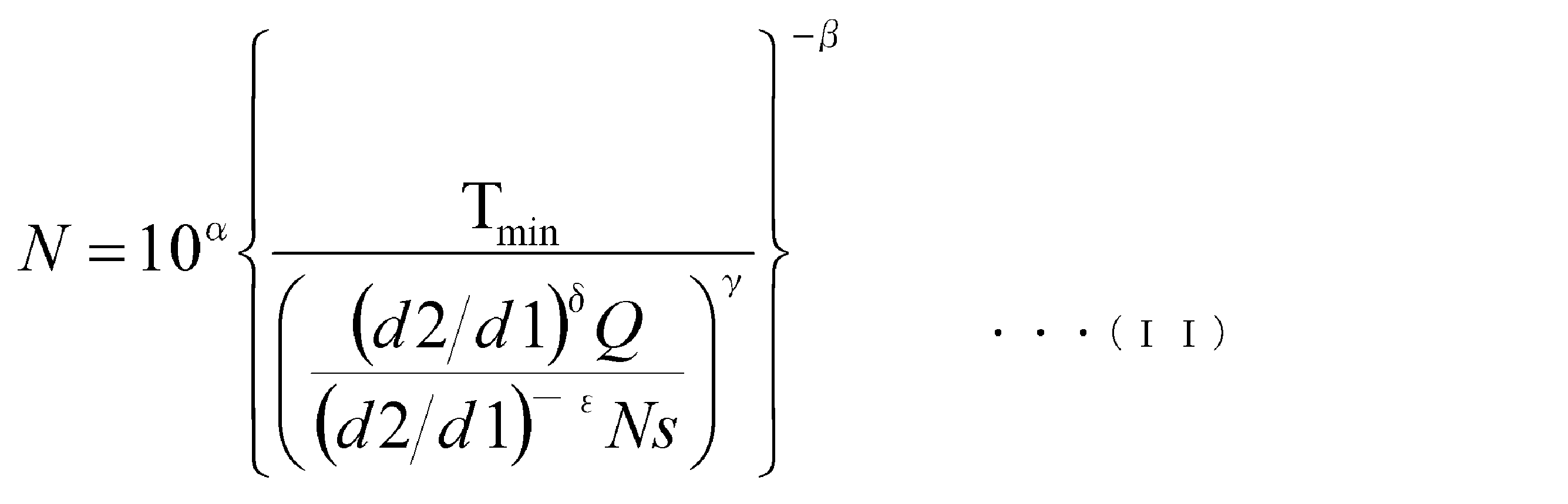
(上記数式(II)中のd1は変更前の前記外径、d2は変更後の前記外径、α、β、γ、δ、εは、全て0以上の定数である。)
(3) 前記製造条件算出手段は、複数の前記L/Dの条件毎に、吐出量Qと前記最小せん断応力履歴値Tminとの関係を表す近似曲線を作成する近似曲線作成ステップと、前記数式(I)に基づいて、前記単位量あたりの未解繊ペレット数Nが所定の値以下になる最小せん断応力履歴値Tminである閾値Tmin決定する閾値Tmin決定ステップと、各近似曲線から前記閾値Tminでの各吐出量(Qn)を算出する吐出量Qn算出ステップと、前記L/Dと前記Qnとの間の関係式を導出する関係式導出ステップと、を備え、前記関係式に基づいて、製造条件を選択するする(1)又は(2)に記載のシミュレーション装置。
(4) 前記スクリューエレメントは、フライト部に切り欠きを有する逆送りのスクリューエレメントである(1)から(3)のいずれかに記載のシミュレーション装置。
(5) (1)から(4)のいずれかに記載のシミュレーション装置の機能をコンピュータで実現するためのプログラム。
(6) (5)に記載のプログラムを記録したコンピュータ読み取り可能な記録媒体。
本発明によれば、ガラス繊維束と熱可塑性樹脂とを混練する際にガラス繊維束が受けるせん断応力の時間積分値の最小値(最小せん断応力履歴値Tmin)を制御することで、ガラス繊維束がモノフィラメントに解繊される製造条件をシミュレーションにより導出することができる。
なお、生産効率に優れた高性能二軸押出機を用いた場合に、特に、ガラス繊維束が解繊せずに樹脂組成物ペレット中に残存することが問題となっている。本発明はこのような高性能な二軸押出機を用いても上記のガラス繊維の未解繊の問題を解消できる。
以下、本発明の実施形態について詳細に説明するが、本発明は、以下の実施形態に何ら限定されるものではなく、本発明の目的の範囲内において、適宜変更を加えて実施することができる。なお、説明が重複する箇所については、適宜説明を省略する場合があるが、発明の要旨を限定するものではない。
本発明のシミュレーション装置は、ガラス繊維強化熱可塑性樹脂組成物ペレットを製造する際の製造条件をシミュレーションにより導出する。本発明のシミュレーション装置について説明する前に、先ず、ガラス繊維強化熱可塑性樹脂組成物ペレットを製造する方法について簡単に説明する。
<ガラス繊維強化熱可塑性樹脂組成物ペレットの製造方法>
ガラス繊維強化熱可塑性樹脂組成物ペレットを製造する方法は、互いに回転して噛み合うスクリューを備えた二軸以上の押出機を用いて、ガラス繊維強化熱可塑性樹脂組成物ペレットを製造する方法である。
ガラス繊維強化熱可塑性樹脂組成物ペレットを製造する方法は、互いに回転して噛み合うスクリューを備えた二軸以上の押出機を用いて、ガラス繊維強化熱可塑性樹脂組成物ペレットを製造する方法である。
具体的には、ガラス繊維強化熱可塑性樹脂組成物ペレットを製造する方法は、例えば、以下の工程を備える。
熱可塑性樹脂を上記押出機に供給して加熱、混練し可塑化する可塑化工程。
可塑化工程後に、一束以上のガラス繊維束を押出機に供給して、上記ガラス繊維束を解繊しながら、解繊されたガラス繊維と可塑化した熱可塑性樹脂とを混練する混練工程。
混練工程後に、ガラス繊維強化熱可塑性樹脂組成物を押出す押出工程。
押出されたガラス繊維強化熱可塑性樹脂組成物をペレット化するペレット化工程。
熱可塑性樹脂を上記押出機に供給して加熱、混練し可塑化する可塑化工程。
可塑化工程後に、一束以上のガラス繊維束を押出機に供給して、上記ガラス繊維束を解繊しながら、解繊されたガラス繊維と可塑化した熱可塑性樹脂とを混練する混練工程。
混練工程後に、ガラス繊維強化熱可塑性樹脂組成物を押出す押出工程。
押出されたガラス繊維強化熱可塑性樹脂組成物をペレット化するペレット化工程。
以下、これらの各工程について簡単に説明する。説明には、図1に記載のスクリュー構成を備える二軸押出機を用いる。この押出機は樹脂可塑化部と混練部とを備える。樹脂可塑化部は供給部、可塑化部、輸送部を備え、混練部は混練部1、混練部2を備える。
[可塑化工程]
可塑化工程では、ホッパから供給された熱可塑性樹脂を移送・溶融して、均質な溶融体を作る。先ず、熱可塑性樹脂について説明し、次いで、ホッパから供給された熱可塑性樹脂が均質な溶融体になるまで(可塑化工程の詳細)を説明する。
可塑化工程では、ホッパから供給された熱可塑性樹脂を移送・溶融して、均質な溶融体を作る。先ず、熱可塑性樹脂について説明し、次いで、ホッパから供給された熱可塑性樹脂が均質な溶融体になるまで(可塑化工程の詳細)を説明する。
(熱可塑性樹脂)
使用する熱可塑性樹脂の種類は特に限定されない。熱可塑性樹脂の具体例としては、ポリプロピレン、ポリアセタール、液晶性樹脂、ポリブチレンテレフタレート、ポリエチレンテレフタレート、ポリフェニレンサルファイド、ナイロン66等が挙げられる。これらの熱可塑性樹脂の中でも特に、粘性の低いものほど、上記ガラス繊維束の未解繊の問題は生じやすい。粘性が低いと溶融状態ではせん断応力が発生し難くなり、モノフィラメントを収束したガラス繊維束は、解繊し難くなるからである。粘性の低い樹脂としては、例えば、ポリブチレンテレフタレート、液晶性樹脂、ポリエチレンテレフタレート、ナイロン66等が挙げられる。
使用する熱可塑性樹脂の種類は特に限定されない。熱可塑性樹脂の具体例としては、ポリプロピレン、ポリアセタール、液晶性樹脂、ポリブチレンテレフタレート、ポリエチレンテレフタレート、ポリフェニレンサルファイド、ナイロン66等が挙げられる。これらの熱可塑性樹脂の中でも特に、粘性の低いものほど、上記ガラス繊維束の未解繊の問題は生じやすい。粘性が低いと溶融状態ではせん断応力が発生し難くなり、モノフィラメントを収束したガラス繊維束は、解繊し難くなるからである。粘性の低い樹脂としては、例えば、ポリブチレンテレフタレート、液晶性樹脂、ポリエチレンテレフタレート、ナイロン66等が挙げられる。
(可塑化工程の詳細)
熱可塑性樹脂の可塑化は図1に記載の二軸押出機の樹脂可塑化部で行われる。樹脂可塑化部は、供給部、可塑化部、輸送部を有する。供給部及び輸送部で使用するスクリューエレメントとしては、例えば順送りフライトからなる搬送用のエレメント等が挙げられる。可塑化部に使用するスクリューエレメントとしては、逆送りフライト、シールリング、順送りニーディングディスク、逆送りニーディングディスク等のスクリューエレメントの組み合わせ等が挙げられる。以下、供給部、可塑化部、輸送部について簡単に説明する。
熱可塑性樹脂の可塑化は図1に記載の二軸押出機の樹脂可塑化部で行われる。樹脂可塑化部は、供給部、可塑化部、輸送部を有する。供給部及び輸送部で使用するスクリューエレメントとしては、例えば順送りフライトからなる搬送用のエレメント等が挙げられる。可塑化部に使用するスクリューエレメントとしては、逆送りフライト、シールリング、順送りニーディングディスク、逆送りニーディングディスク等のスクリューエレメントの組み合わせ等が挙げられる。以下、供給部、可塑化部、輸送部について簡単に説明する。
供給部では樹脂ペレットを移送する。供給部は、一般に樹脂ペレットが溶融しないような温度設定で、樹脂ペレットをホッパ側からダイ方向側に移送する働きをする。
このように樹脂ペレットが溶融しないような低温で行われるが、溶融の準備段階として外部ヒータによる予熱が行われる場合がある。また、樹脂ペレットは、回転するスクリューとシリンダーに挟まれるため、樹脂ペレットには摩擦力が加わり、摩擦熱が発生する。上記予熱や摩擦熱によって溶融し始める場合もある。
このように樹脂ペレットが溶融しないような低温で行われるが、溶融の準備段階として外部ヒータによる予熱が行われる場合がある。また、樹脂ペレットは、回転するスクリューとシリンダーに挟まれるため、樹脂ペレットには摩擦力が加わり、摩擦熱が発生する。上記予熱や摩擦熱によって溶融し始める場合もある。
場合によっては、供給部では、樹脂ペレットの移送がスムーズに進むように、スクリューの溝深さの調整、予熱の温度調整を従来公知の方法で行う必要がある。
可塑化部では、供給部から移送された樹脂ペレットに圧力を加えて樹脂ペレットを溶融する。可塑化部では、樹脂ペレットにせん断応力が加わる結果、樹脂ペレットが溶融しながら、さらに前方(ホッパからダイの方向)へと移送される。
輸送部では、可塑化部で溶融された熱可塑性樹脂(以下、溶融樹脂という場合がある)を移送する。輸送部では、可塑化部で均質な溶融状態になった熱可塑性樹脂を混練部まで移送する。
[混練工程]
混練工程では、可塑化工程後に、一束以上のガラス繊維束を押出機に供給して、上記ガラス繊維束を解繊しながら、解繊されたガラス繊維と可塑化した熱可塑性樹脂とを混練する。
混練工程では、可塑化工程後に、一束以上のガラス繊維束を押出機に供給して、上記ガラス繊維束を解繊しながら、解繊されたガラス繊維と可塑化した熱可塑性樹脂とを混練する。
混練工程は図1に示す二軸押出機の混練部で行われる。混練部は、混練部1、混練部2からなり、混練部2は混練部21、混練部22からなる。混練部1で使用するスクリューエレメントとしては、例えば順送りフライトからなる搬送用のエレメントが挙げられる。混連部21及び22に使用するスクリューエレメントとしては、逆送りフライト、シールリング、順送りニーディングディスク、逆送りニーディングディスク等のスクリューエレメントの組み合わせが挙げられる。例えば、混練部21に順送りニーディングディスクを用いて、混練部22に逆送りフライトを用いる等の組み合わせが挙げられる。また、後述する通り、本発明の製造方法においては、フライト部に切り欠きを有する逆送りのスクリューエレメントを混練部に用いることが好ましい(本実施形態では混練部21がフライト部に切り欠きを有する逆送りのスクリューエレメントである)。理由については後述する。
(混練部1)
混練部1では副原料フィード口から投入されたガラス繊維束と溶融樹脂とを混練部2まで搬送する。この混練部1での搬送においてはスクリューの溝内部にガラス繊維束や樹脂が完全に充満せず、ガラス繊維束にせん断力がかからない領域である。
混練部1では副原料フィード口から投入されたガラス繊維束と溶融樹脂とを混練部2まで搬送する。この混練部1での搬送においてはスクリューの溝内部にガラス繊維束や樹脂が完全に充満せず、ガラス繊維束にせん断力がかからない領域である。
ガラス繊維束について簡単に説明する。ガラス繊維束は、300本から3000本のモノフィラメントが束になったチョップドストランド、1100本か2200本が束になったチョップドストランドが好ましく使用できる。また、モノフィラメントの径は、特に限定されないが、6μmから20μmの範囲のものが好ましく、6μm、10μm、13μmのものが物性上特に好ましい。なお、ロービングのままモノフィラメントの束を連続的に二軸押出機に供給することもできる。しかし、ロービングをカットしたチョップドストランドは、輸送、二軸押出機への供給において、取り扱いが容易である。このため、チョップドストランドの使用が好ましい。
(混練部2)
混練部2では、ガラス繊維束及び溶融樹脂にせん断応力がかかる。せん断応力がかかることでガラス繊維束の解繊及びモノフィラメントと溶融樹脂との混練が進む。ここで、混練部2でのスクリューの回転数が回転数Nsにあたる。また、混練部21におけるスクリュー長さがLであり、スクリュー外径がDである。
混練部2では、ガラス繊維束及び溶融樹脂にせん断応力がかかる。せん断応力がかかることでガラス繊維束の解繊及びモノフィラメントと溶融樹脂との混練が進む。ここで、混練部2でのスクリューの回転数が回転数Nsにあたる。また、混練部21におけるスクリュー長さがLであり、スクリュー外径がDである。
本願発明の製造方法の特徴は、混練部2でのガラス繊維束と溶融樹脂との混練の結果、未解繊のガラス繊維束がペレット中に残存しないことにある。この効果を得るためには、特定の製造条件で樹脂組成物ペレットの製造を行う必要がある。本発明は、この特定の製造条件を導出するためのシミュレーション装置である。
[押出工程、ペレット化工程]
ガラス繊維強化熱可塑性樹脂組成物がどのように押出され、どのようにペレット化されるかは特に限定されないが、例えば、棒状に押出されたガラス繊維強化熱可塑性樹脂組成物を切断してペレット化することができる。なお、切断方法は特に限定されず、従来公知の方法を利用することができる。なお、押出工程における吐出量が吐出量Qにあたる。
ガラス繊維強化熱可塑性樹脂組成物がどのように押出され、どのようにペレット化されるかは特に限定されないが、例えば、棒状に押出されたガラス繊維強化熱可塑性樹脂組成物を切断してペレット化することができる。なお、切断方法は特に限定されず、従来公知の方法を利用することができる。なお、押出工程における吐出量が吐出量Qにあたる。
<シミュレーション装置>
本発明のシミュレーション装置は、図2に示すように、入力手段と、製造条件算出手段と、出力手段とを備える。
本発明のシミュレーション装置は、図2に示すように、入力手段と、製造条件算出手段と、出力手段とを備える。
入力手段は、L/D、吐出量Q、スクリュー回転数Ns(L/D、吐出量Q及びスクリュー回転数Nsを併せて、「最小せん断応力履歴値の導出条件」という場合がある。)、未解繊ペレット数N、最小せん断応力履歴値Tminの組が複数入力される。
製造条件算出手段では、入力された最小せん断応力履歴値の導出条件、最小せん断応力履歴値Tmin、単位量あたりの未解繊ペレット数Nに基づいて、上記数式(I)を導出し、未解繊ペレット数Nが所定の値未満になる製造条件を算出する。本実施形態では1kgあたりの未解繊ペレット数Nが1未満の場合について説明する。
出力手段では、製造条件算出手段で算出された製造条件を出力する。
製造条件算出手段では、入力された最小せん断応力履歴値の導出条件、最小せん断応力履歴値Tmin、単位量あたりの未解繊ペレット数Nに基づいて、上記数式(I)を導出し、未解繊ペレット数Nが所定の値未満になる製造条件を算出する。本実施形態では1kgあたりの未解繊ペレット数Nが1未満の場合について説明する。
出力手段では、製造条件算出手段で算出された製造条件を出力する。
先ず、入力手段に入力される各パラメーターについて説明する。なお、L、D、吐出量Q、スクリュー回転数Nsについては上述の通りであり、説明を省略する。
最小せん断応力履歴値Tminは、従来公知の二軸押出機内3次元流動解析ソフトウェアを用いて導出することができる。例えば、実施例に記載するような、粒子追跡解析で導出できる。最小せん断応力履歴値Tminはせん断応力の時間積分を行うことで得られる時間積分値であるが、積分区間は、溶融樹脂及びガラス繊維束にせん断応力がかかる区間であり、図1に示す押出機の場合には、混練部2の区間である。
最小せん断応力履歴値の導出方法は、特に限定されない。市販のソフトウェアを用いて導出する方法、実験により導出する方法等が挙げられる。
以下、本発明のシミュレーション装置の動作及びシミュレーション方法について、図3のフローチャートに基づいて説明する。
入力された情報(最小せん断応力履歴値の導出条件、単位量あたりの未解繊ペレット数、最小せん断応力履歴値)に基づいて、下記数式(I)を導出する(S1)。

数式(I)の導出にあたって、定数γは、縦軸をNとし、横軸をTminとした2次元のグラフを作成したときに、Q/Nsの影響が小さくなるように決定する。
α、β、γはどのような方法で導出してもよいが例えば以下の方法で導出することができる。
最初に、所定のQ/Nsの条件における入力データに基づいて、下記数式(III)を導出する(S11)。

(上記数式(I)中のα、βは、0以上の定数である。)
導出された数式(III)に基づいて、α、βを決定する。
γを導出するために必要な数式(III)の数になるまで、所定のQ/Nsの条件を異なる条件に変更して、数式(III)の導出を繰り返す(S12)。なお、γを導出するために必要なQ/Nsの条件数は予め決めて設定しておく。数式の数は3以上であることが好ましい。
次いで、得られた複数の数式(III)の中から基準となる数式(III)を決定し、α、βを決定する(S13)。選択方法は特に限定されず、任意に決定することができる。例えば、最初に導出した数式(III)を基準にすることができる。この基準となる数式(III)のα、βが数式(I)のα、βとなる。
Q/Nsの条件によって異なる数式(III)を、ひとつの数式でまとめるためのγを導出する(S14)。Q/Nsの条件によらず適用できるようなγの値を、従来公知の近似方法(例えば、最小二乗法、ガウスニュートン法、シンプレックス法という方法等)を用いて決定する。
Nが所定数未満になるような製造条件を算出する(S2)。製造条件の算出結果が出力手段によって出力されることで終了する。製造条件の算出は例えば、以下の方法で行うことができる。
検討を行なう製造条件のNs、Q、Tminを導出した数式(I)に代入して計算を行なう(S21)。ここで、検討を行なう製造条件のNs、Q、Tminは、コンピュータが自動で任意に選択して決定してもよいし、予め決めておいたNs、Q、Tminを代入するように設定しておいてもよい。Ns、Q、Tmin、Q/Nsの少なくとも一つを固定して、製造条件の算出を行なってもよい。
計算した結果、Nが所定数(本実施形態では1)以上の場合には、所定のNs、Q、Tminを、Tminがより大きい条件、又はQ/Nsがより小さい条件に変更して、これらの値を、数式(I)に代入する(S22)。Nが以上になる場合に、どのように条件を変更するかを予め設定しておいてもよい。
Nが所定数未満(例えば1未満)の条件であれば、出力手段により製造条件が出力される(S23)。
Nが所定数未満になる製造条件が、予め決めた数得られるまで、製造条件の算出を繰り返す(S24)。算出する製造条件の数は任意に決定する。所望の数の製造条件が得られたら、シミュレーションは終了する。
なお、数式(I)は、熱可塑性樹脂の種類、ガラス繊維束の種類が異なれば、新たに数式(I)を導出しなおす必要がある。そして、予め導出された数式(I)を用いる場合には、最小せん断応力履歴値の導出条件、未解繊ペレット数、最小せん断応力履歴値を入力した後、Nが所定数未満になるような製造条件の算出(S2)のみを行なえば、製造条件を算出することができる。
[押出機サイズを変更した場合の製造条件の決定]
一般的に、小型の試作機を用いて製造条件の検討を行い、大型の量産機で樹脂組成物ペレットの製造を行う。この量産機による製造を行う場合、小型の試作機を用いて導出した数式(I)を用いると、単位量あたりの未解繊ペレット数が所定の値未満になるような製造条件を正確に選択することができない。同じ吐出量及び同じスクリュー回転数の条件であっても、小型の試作機と大型の量産機とでは、バレルからの伝熱量が異なり、溶融樹脂にかかる熱エネルギーが異なるからである。
一般的に、小型の試作機を用いて製造条件の検討を行い、大型の量産機で樹脂組成物ペレットの製造を行う。この量産機による製造を行う場合、小型の試作機を用いて導出した数式(I)を用いると、単位量あたりの未解繊ペレット数が所定の値未満になるような製造条件を正確に選択することができない。同じ吐出量及び同じスクリュー回転数の条件であっても、小型の試作機と大型の量産機とでは、バレルからの伝熱量が異なり、溶融樹脂にかかる熱エネルギーが異なるからである。
小型の試作機ではなく大型の量産機でシミュレーション、実験等を行い、上述の方法と同様の方法で、大型量産機での上記数式(I)を導出することも可能ではあるが、時間と費用と手間がかかる。以下に説明する方法を行うことで、小型の試作機で導出した数式(I)から大型の量産機で用いることができる数式(II)を導出することができる。
スクリューエレメントの外径Dが、d1からd2に変更になる場合、試作機での吐出量Qmと量産機での吐出量QMとの間には下記数式(IV)が成立し、試作機でのスクリュー回転数Nsmと量産機でのスクリュー回転数NsMとの間には下記数式(V)が成立する。


溶融樹脂にかかる比エネルギーが同等になるように上記数式(IV)、(V)のδ及びεを決定する。δ及びεの決定方法としては、理論的に決定する方法、実験的に決定する方法のいずれでもよい。理論的に決定する方法としては、一般的には、断熱状態と仮定して、目的関数を比エネルギー、あるいは総せん断量、滞留時間等が、小型機と大型機で一致するように、パラメーターδ及びεが導出される。小型機と大型機の伝熱量の差を仮定して、目的関数としての比エネルギーが、小型機と大型機で一致するように、パラメーターδ及びεを導出することもできる。実験的に決定する方法としては、目的関数を、比エネルギーとするか、もしくは、物性を示すパラメーターを採用し、目的関数が、小型機と大型機とで一致するように、統計的にパラメーターδ及びεを算出するような方法が挙げられる。
小型の試作機と大型の量産機との間に成立する上記数式(IV)、(V)を導出することで、大型機に成立する単位量あたりの未解繊ペレット数Nと最小せん断応力履歴値Tminとの間の下記数式(II)を容易に導出することができる。

次いで、押出機サイズの変更を行った場合の、本発明のシミュレーション装置の動作及びシミュレーション方法について、図4のフローチャートに基づいて説明する。
d2の値を入力手段に入力することでシミュレーションが開始される。なお、上記数式(IV)、(V)における、δ、εを実験で導出する場合には、実験で導出したこれらの値も入力する(実験的に導出した場合には、下記S3工程は省略する)
先ず、上記数式(IV)、(V)のδ、εを導出する(S3)。断熱状態と仮定して、目的関数を比エネルギー、あるいは総せん断量、滞留時間等が、小型機と大型機で一致するように、これらの値を算出する。
次いで、数式(II)を導出する(S4)。数式(II)の導出後は、上述の方法(S2)と同様にして製造条件を算出することができるため、説明を省略する。
[簡便な製造条件の決定]
上記のような数式(I)、(II)を用いることで、未解繊のガラス繊維束を含む樹脂組成物ペレットが製造されないような製造条件を決定することができる。しかしながら、製造条件の検討の都度、数式(I)又は(II)にNs、Q、Tminを代入する方法の場合、非常に時間がかかる(特に、シミュレーションによるTminの導出に時間がかかる。)。そこで、以下の方法で、L/Dと、許容される中で最大の吐出量(最大吐出量)との関係を導出することで、この関係に基づいて、容易に製造条件を決定できる。その結果、Nが所定の値未満の条件を満たす製造条件を決定することができる。具体的には、上述のS1に続いて、以下の方法でS2を実施する。
上記のような数式(I)、(II)を用いることで、未解繊のガラス繊維束を含む樹脂組成物ペレットが製造されないような製造条件を決定することができる。しかしながら、製造条件の検討の都度、数式(I)又は(II)にNs、Q、Tminを代入する方法の場合、非常に時間がかかる(特に、シミュレーションによるTminの導出に時間がかかる。)。そこで、以下の方法で、L/Dと、許容される中で最大の吐出量(最大吐出量)との関係を導出することで、この関係に基づいて、容易に製造条件を決定できる。その結果、Nが所定の値未満の条件を満たす製造条件を決定することができる。具体的には、上述のS1に続いて、以下の方法でS2を実施する。
以下に説明するL/Dと最大吐出量との関係を導出する方法は、近似曲線作成ステップ(S2A)と、近似曲線閾値Tmin決定ステップ(S2B)と、吐出量Qn算出ステップ(S2C)と、関係式導出ステップ(S2D)と、を備える。そして、関係式導出ステップ(S2D)で得られた関係式に基づいて、選択可能な製造条件の範囲を決定する製造条件範囲決定ステップ(S2E)と、製造条件範囲を出力する製造条件範囲出力ステップ(S2F)とを行い、シミュレーションが終了する。以下に各ステップについて詳細に説明する。説明には図5に示すフローチャートを用いる。
(近似曲線作成ステップ(S2A))
近似曲線作成ステップでは、Q/Ns=一定とし、吐出量Qと最小せん断応力履歴値Tminとの関係を表す近似曲線を作成する。
近似曲線作成ステップでは、Q/Ns=一定とし、吐出量Qと最小せん断応力履歴値Tminとの関係を表す近似曲線を作成する。
具体的には、例えば、S1で入力手段に入力された(L(混練部21の長さ)/D)、吐出量Q、スクリュー回転数Ns、最小せん断応力履歴値Tminの情報に基づいて近似曲線を作成することができる。
例えば、入力された条件である(QA、TminA)、(QB、TminB)、(QC、TminC)から近似曲線を作成する。近似曲線の作成方法は、特に限定されないが、例えば最小二乗法、ガウスニュートン法、シンプレックス法という方法等という方法で作成することができる。なお、図6(a)に近似曲線F1を示した。
また、近似曲線作成ステップ(S2A)においては、混練部21の長さ(L)/スクリューエレメントの外径(D)(L/D)の条件を少なくとも1回変更して、各(L/D)での吐出量Qと最小せん断応力履歴値Tminとの関係を表す近似曲線を、上記と同様の方法で作成する。なお、リード長とは、ガラス繊維束を解繊しながら、解繊されたガラス繊維と可塑化した熱可塑性樹脂とを混練するためのニーディングディスクのリード長を指す(混練部21)。
近似曲線作成ステップ(S2A)では、近似曲線を少なくとも一つ導出すればよいが、ここでは近似曲線F2、F3を導出したとする。図6(b)に近似曲線F1、F2、F3を示した。
(閾値Tmin決定ステップ(S2B))
閾値Tmin決定ステップとは、上記式(I)においてペレット数Nが所定の値未満(本実施形態では1とする。)になる最小せん断応力履歴値Tminを決定するステップである。最小せん断応力履歴値Tminは、未解繊ペレット数Nを縦軸、最小せん断応力履歴値Tminを横軸とするグラフを作成することにより導出することができる。
閾値Tmin決定ステップとは、上記式(I)においてペレット数Nが所定の値未満(本実施形態では1とする。)になる最小せん断応力履歴値Tminを決定するステップである。最小せん断応力履歴値Tminは、未解繊ペレット数Nを縦軸、最小せん断応力履歴値Tminを横軸とするグラフを作成することにより導出することができる。
(吐出量Qn算出ステップ(S2C))
吐出量Qn算出ステップとは、作成した各近似曲線から閾値Tminでの各吐出量(Qn)を算出するステップである。
吐出量Qn算出ステップとは、作成した各近似曲線から閾値Tminでの各吐出量(Qn)を算出するステップである。
近似曲線F1に閾値Tminを代入して算出される吐出量をQ1、近似曲線F2に閾値Tminを代入して算出される吐出量をQ2、近似曲線F3に閾値Tminを代入して算出される吐出量をQ3とする。Q1,Q2、Q3を図6(c)に示した。
(関係式導出ステップ(S2D))
関係式導出ステップとは、各近似曲線でのL/Dと上記各吐出量(Qn)とから、上記L/DとQnとの関係を一次関数((Q)=f(L/D))によって近似するステップである。
関係式導出ステップとは、各近似曲線でのL/Dと上記各吐出量(Qn)とから、上記L/DとQnとの関係を一次関数((Q)=f(L/D))によって近似するステップである。
吐出量Q1を導出したときの、L/DをL1/D1とし、吐出量Q2を導出したときの上記L/DをL2/D2とし、吐出量Q3を導出したときの上記L/DをL3/D3とする。横軸に混練部L/D、縦軸に吐出量Qとし、(Q1、L1/D1)、(Q2、L2/D2)、(Q3、L3/D3)から一次関数((Q)=f(L/D))を導出する。導出結果を図7(a)に示す。なお、導出方法については特に限定されないが、例えば最小二乗法等の方法で導出することができる。
以上のようにして、L/Dと最大吐出量Qnとの関係が導出される。この関係に基づくことで、容易に製造条件を決定できる。例えば、製造条件範囲決定ステップ(S2E)、製造条件範囲出力ステップ(S2F)を行なうことで製造条件を決定することができる。
[製造条件範囲決定ステップ(S2E)]
製造条件範囲決定ステップでは、未解繊ガラス繊維が含まれる単位量あたりのペレット数が所定の値未満の製造条件範囲を決定する。具体的には(Q)<f(L/D)を満たす領域を決定する。この領域から製造条件を選択すれば、最小せん断応力履歴値Tminは閾値Tmin以上になり、未解繊ガラス繊維束を含む単位量あたりのペレット数は所定の値未満になる。
製造条件範囲決定ステップでは、未解繊ガラス繊維が含まれる単位量あたりのペレット数が所定の値未満の製造条件範囲を決定する。具体的には(Q)<f(L/D)を満たす領域を決定する。この領域から製造条件を選択すれば、最小せん断応力履歴値Tminは閾値Tmin以上になり、未解繊ガラス繊維束を含む単位量あたりのペレット数は所定の値未満になる。
[製造条件範囲出力ステップ(S2F)]
製造条件範囲出力ステップ(S2F)は、上記製造条件範囲決定ステップ(S2E)で決定された製造条件範囲を、出力手段により出力するステップである。この出力により、所望の製造条件が得られるので、シミュレーションは終了する。
製造条件範囲出力ステップ(S2F)は、上記製造条件範囲決定ステップ(S2E)で決定された製造条件範囲を、出力手段により出力するステップである。この出力により、所望の製造条件が得られるので、シミュレーションは終了する。
なお、押出機内の樹脂温度を、樹脂が劣化する温度以下に維持する必要がある。図7(a)の点線Zは、樹脂の劣化限界の温度を示す線である。これと(Q)=f(L/D)の交点まで吐出量を上げることができる。特に熱で劣化しやすい樹脂の場合には、樹脂が劣化しないように、例えば、製造条件範囲決定ステップ(S2E)において、樹脂の劣化限界の温度を示す線を考慮する。
なお、数式(I)の代わりに数式(II)を用いれば、大型の量産機の場合にも上記の簡便な製造条件の決定を行うことができる。
なお、混練部21に、特開2002-120271に記載されているような切り欠きのあるスクリューエレメントを使用した場合の(Q)BMS=f(L/D)BMSを図7(b)に示した。切り欠きのあるスクリューエレメントを用いることで製造条件の選択の幅が広がるため好ましい。
以下、実施例及び比較例を示し、本発明を具体的に説明するが、本発明はこれらの実施例に限定されるものではない。
実施例においては以下の材料を用いた。
熱可塑性樹脂:ポリブチレンテレフタレート樹脂(PBT)(メルトインデックス(MI)=70g/10分)
カーボンマスターバッチ
ガラス繊維束:直径が13μmのモノフィラメントを2200本束ねた長さ3mmのチョップドストランド
また、組成は以下の通りである。
PBTが67.5質量%、カーボンマスターバッチが2.5質量%、ガラス繊維束が30質量%
押出条件は以下の通りである。
押出機:同方向完全噛み合い型二軸押出機TEX44αII(日本製鋼所製)スクリューエレメントの外径(D)が0.047m
押出条件;

バレル温度;220℃
スクリューデザイン;
(1)概略
押出機のスクリューは図1のように表すことができ、図1に示すスクリューパターンの概略は以下の通りである。
C1:ホッパ
C2~C5:供給部
C5~C6:可塑化部
C6~C8:輸送部
C9:副原料フィード口
C10:混練部1
C11:混練部2(混練部21、混練部22からなる)
(2)実施例で使用した具体的なスクリューパターンは、図8に示す通りである。なお、ニーディングディスクで、各ディスクが送り方向に45°位相がずれているものをFKとし、逆送りの1条のフライトで切り欠きのあるエレメントをBMSとする。
図8(a)に示すスクリューパターンをFK1.0D(L/D=1)、
図8(b)に示すスクリューパターンをFK2.0D(L/D=2)、
図8(c)に示すスクリューパターンをBMS1.0D(L/D=1)、
図8(d)に示すスクリューパターンをBMS2.0D(L/D=2)、
図8(e)に示すスクリューパターンをBMS2.5D(L/D=2.5)、
とする。L/Dは、混練部21のリード長(L)とスクリューエレメントの外径(D)との比(L/D)である。
(3)スクリューの形状
図8に示すスクリューパターンはそれぞれC11の混練部2のみ異なる。C11の混練部2のスクリューの形状を図9に示す。図8(a)のパターンのスクリュー形状を図9(a)に示し、図8(b)のパターンのスクリュー形状を図9(b)に示し、図8(c)のパターンのスクリュー形状を図9(c)に示し、図8(d)のパターンのスクリュー形状を図9(d)に示し、図8(e)のパターンのスクリュー形状を図9(e)に示した。
図9(a)に示すスクリューは混練部21が長さ1.0Dの順送りニーディングディスク、混練部22が長さ0.5Dの逆送りフライト
図9(b)に示すスクリューは混練部21が長さ2.0Dの順送りニーディングディスク、混練部22が長さ0.5Dの逆送りフライト
図9(c)に示すスクリューは混練部21が長さ1.0Dの切り欠き含有の1条の逆送りニーディングディスク、混練部22が長さ0.5Dの逆送りフライト
図9(d)に示すスクリューは混練部21が長さ2.0Dの切り欠き含有の1条の逆送りニーディングディスク、混練部22が長さ0.5Dの逆送りフライト
図9(e)に示すスクリューは混練部21が長さ2.5Dの切り欠き含有の1条の逆送りニーディングディスク、混練部22が長さ0.5Dの逆送りフライト
熱可塑性樹脂:ポリブチレンテレフタレート樹脂(PBT)(メルトインデックス(MI)=70g/10分)
カーボンマスターバッチ
ガラス繊維束:直径が13μmのモノフィラメントを2200本束ねた長さ3mmのチョップドストランド
また、組成は以下の通りである。
PBTが67.5質量%、カーボンマスターバッチが2.5質量%、ガラス繊維束が30質量%
押出条件は以下の通りである。
押出機:同方向完全噛み合い型二軸押出機TEX44αII(日本製鋼所製)スクリューエレメントの外径(D)が0.047m
押出条件;
スクリューデザイン;
(1)概略
押出機のスクリューは図1のように表すことができ、図1に示すスクリューパターンの概略は以下の通りである。
C1:ホッパ
C2~C5:供給部
C5~C6:可塑化部
C6~C8:輸送部
C9:副原料フィード口
C10:混練部1
C11:混練部2(混練部21、混練部22からなる)
(2)実施例で使用した具体的なスクリューパターンは、図8に示す通りである。なお、ニーディングディスクで、各ディスクが送り方向に45°位相がずれているものをFKとし、逆送りの1条のフライトで切り欠きのあるエレメントをBMSとする。
図8(a)に示すスクリューパターンをFK1.0D(L/D=1)、
図8(b)に示すスクリューパターンをFK2.0D(L/D=2)、
図8(c)に示すスクリューパターンをBMS1.0D(L/D=1)、
図8(d)に示すスクリューパターンをBMS2.0D(L/D=2)、
図8(e)に示すスクリューパターンをBMS2.5D(L/D=2.5)、
とする。L/Dは、混練部21のリード長(L)とスクリューエレメントの外径(D)との比(L/D)である。
(3)スクリューの形状
図8に示すスクリューパターンはそれぞれC11の混練部2のみ異なる。C11の混練部2のスクリューの形状を図9に示す。図8(a)のパターンのスクリュー形状を図9(a)に示し、図8(b)のパターンのスクリュー形状を図9(b)に示し、図8(c)のパターンのスクリュー形状を図9(c)に示し、図8(d)のパターンのスクリュー形状を図9(d)に示し、図8(e)のパターンのスクリュー形状を図9(e)に示した。
図9(a)に示すスクリューは混練部21が長さ1.0Dの順送りニーディングディスク、混練部22が長さ0.5Dの逆送りフライト
図9(b)に示すスクリューは混練部21が長さ2.0Dの順送りニーディングディスク、混練部22が長さ0.5Dの逆送りフライト
図9(c)に示すスクリューは混練部21が長さ1.0Dの切り欠き含有の1条の逆送りニーディングディスク、混練部22が長さ0.5Dの逆送りフライト
図9(d)に示すスクリューは混練部21が長さ2.0Dの切り欠き含有の1条の逆送りニーディングディスク、混練部22が長さ0.5Dの逆送りフライト
図9(e)に示すスクリューは混練部21が長さ2.5Dの切り欠き含有の1条の逆送りニーディングディスク、混練部22が長さ0.5Dの逆送りフライト
[数式(III)の導出]
Q/Ns=1.0の条件で、図10に示すような最小せん断応力履歴値(Pa・sec)とガラス繊維束の一部又は全部が未解繊のペレット数(個/ペレット10kg)との関係を求めた。具体的には以下のような方法で導出した。
Q/Ns=1.0の条件で、図10に示すような最小せん断応力履歴値(Pa・sec)とガラス繊維束の一部又は全部が未解繊のペレット数(個/ペレット10kg)との関係を求めた。具体的には以下のような方法で導出した。
先ず、数式(III)の導出に必要な、L/D、吐出量Q、スクリュー回転数Ns、未解繊ペレット数N、最小せん断応力履歴値Tminの組を複数決定する。L/D、吐出量Q、スクリュー回転数Nsを任意に決めて、以下の方法で、最小せん断応力履歴値Tminを導出し、実験により未解繊ペレット数Nを求めた。具体的には以下のようにして求めた。
先ず、シミュレーションによる最小せん断応力履歴値(Pa・sec)の導出について説明する。
二軸押出機内3次元流動解析ソフト(アールフロー社製ScrewFlow-Multi)を用いて同方向完全噛み合い型二軸押出機内の樹脂挙動を解析した。
解析の際に用いた支配方程式は、連続式(A)、ナビエ-ストークス式(B)、温度バランス式(C)である。



二軸押出機内3次元流動解析ソフト(アールフロー社製ScrewFlow-Multi)を用いて同方向完全噛み合い型二軸押出機内の樹脂挙動を解析した。
解析の際に用いた支配方程式は、連続式(A)、ナビエ-ストークス式(B)、温度バランス式(C)である。
解析仮定として、非圧縮性流体で、完全溶融・完全充満とした。また、粘度近似式はアレニウス近似及びWLF近似を使用した。解析手法は、有限体積法、SOR法、SIMPLEアルゴリズムであり、計算としては、まず定常解析を行い、これを初期値として、非定常解析を行った。非定常解析の後、トレーサー粒子を配置(約5000個)して、トレーサー粒子にかかる局所情報を収集した(粒子追跡解析)。せん断応力の時間積分値の最小値Tminは、トレーサー粒子にかかる局所情報のせん断応力を時間積分し、全粒子の最小値を求めたものである。
次いで、実験による未解繊ペレット数の導出について説明する。
PBTを二軸押出機に供給した後、上記押出条件で、ガラスのチョップドストランドを供給し、混練混合した後、ダイから樹脂組成物を押出し、溶融した樹脂組成をダイから引取りストランドにして、水槽でストランドを冷却固化して、カッターで、ストランドを3mmの長さに切断してペレットを作成した。ペレットを10kg採取し、黒色のペレットの中のガラス未解繊(銀色の凝集塊)を目視にて探し、ガラス未解繊を含んだペレットの個数を数えた。
PBTを二軸押出機に供給した後、上記押出条件で、ガラスのチョップドストランドを供給し、混練混合した後、ダイから樹脂組成物を押出し、溶融した樹脂組成をダイから引取りストランドにして、水槽でストランドを冷却固化して、カッターで、ストランドを3mmの長さに切断してペレットを作成した。ペレットを10kg採取し、黒色のペレットの中のガラス未解繊(銀色の凝集塊)を目視にて探し、ガラス未解繊を含んだペレットの個数を数えた。
未解繊ペレット数と最小せん断応力履歴値と間の関係を表す近似曲線(相関線)を、最小二乗方法で求めた。Q/Ns=1.0で、混練部2に前述のように図8(a)から(e)の異なるエレメントを入れ、かつ、異なるQで実験とシミュレーションを行った結果、以下のようなひとつの近似曲線が得られた。近似曲線については図10に示した。

即ち、上記数式(III)のαが11.5042、βが-2.200となった。
Q/Ns=0.8、Q/Ns=0.5の条件でも、上記と同様にして、図11に示すように、最小せん断応力履歴値(Pa・sec)とガラス繊維束の一部又は全部が未解繊のペレット数(個/ペレット10kg)との関係(相関線)を求めた。なお、図11にはQ/Ns=1.0の場合の相関線についても示した。
図11に示すように、Q/Ns毎に相関線が異なる。そこで、上記数式(I)の形式の関数に最小二乗法で近似した。近似曲線を図12に示した。図12に示すように、Q/Nsにほとんど依存しない一つの相関線で近似できた。なお、γは3.0であった。
図11に示すように、所定の最小せん断応力履歴値以上であれば、単位量あたりの未解繊ペレット数が所定の値未満になることが確認できた。
[押出機サイズを変更した場合の製造条件の決定]
スクリューエレメントの外径(D)の条件を0.047mから0.069mに変更した。溶融樹脂にかかる比エネルギーが同等になるように上記数式(V)、(VI)のδ及びεを上述の方法で検討し、成形加工(第11巻、第11号、1999年、910頁から913頁に記載)の方法で補正して決定した。δが2.5、εが0.5であった。
スクリューエレメントの外径(D)の条件を0.047mから0.069mに変更した。溶融樹脂にかかる比エネルギーが同等になるように上記数式(V)、(VI)のδ及びεを上述の方法で検討し、成形加工(第11巻、第11号、1999年、910頁から913頁に記載)の方法で補正して決定した。δが2.5、εが0.5であった。
最終的に量産機では、以下の数式になる。

(K=1.03823×10⁻⁴[m3]、D3=0.3285[m3])
比エネルギーが同等になるように調整した上記の式を用いれば、未解繊ペレット数が0になる条件をシミュレーションで最小せん断応力履歴値を導出することにより確認することができる。
[簡便な製造条件の決定方法]
上記数式(VII)を用いる。
上記数式(VII)を用いる。
(近似曲線作成ステップ)
数式(VII)を導出する際に得たデータに基づいて、吐出量と最小せん断応力履歴値との関係を導出した。導出結果を図13(a)に示した。なお、図13(a)には近似曲線も併せて示している。
数式(VII)を導出する際に得たデータに基づいて、吐出量と最小せん断応力履歴値との関係を導出した。導出結果を図13(a)に示した。なお、図13(a)には近似曲線も併せて示している。
Q/Ns=0.8の場合についても同様の方法で、近似曲線を作成した。結果を図13(b)に示した。
(閾値Tmin決定ステップ)
未解繊ペレット数N(個/ペレット10kg)が1未満になる条件は、図12から求めると78000Pa・secであった。
未解繊ペレット数N(個/ペレット1kg)が0.4未満になるよう設定した場合、図12から求めると最小せん断応力履歴値は78000Pa・secであった。
未解繊ペレット数N(個/ペレット10kg)が1未満になる条件は、図12から求めると78000Pa・secであった。
未解繊ペレット数N(個/ペレット1kg)が0.4未満になるよう設定した場合、図12から求めると最小せん断応力履歴値は78000Pa・secであった。
(吐出量Qn算出ステップ)
78000Pa・secを図10中に点線で示した。Q/Ns=1.0と0.8の場合に各近似曲線で最小せん断応力履歴値が78000Pa・secになる吐出量を表2にまとめた。

78000Pa・secを図10中に点線で示した。Q/Ns=1.0と0.8の場合に各近似曲線で最小せん断応力履歴値が78000Pa・secになる吐出量を表2にまとめた。
(関係式導出ステップ、製造条件決定ステップ)
表2の結果を図14にまとめた。図14に示す各直線は、L/D毎に未解繊ペレットが所定の値になる最大の吐出量を示すことから、容易に製造条件を決定することができる。また、図14には、樹脂の劣化限界の温度を示す線(劣化限界線)も併せて示した。劣化限界線との交点までの吐出量から製造条件を選択する必要がある。
表2の結果を図14にまとめた。図14に示す各直線は、L/D毎に未解繊ペレットが所定の値になる最大の吐出量を示すことから、容易に製造条件を決定することができる。また、図14には、樹脂の劣化限界の温度を示す線(劣化限界線)も併せて示した。劣化限界線との交点までの吐出量から製造条件を選択する必要がある。
また、フライト部に切り欠きを有するスクリューエレメントを混練部21に用いることで、製造条件の選択の幅が広がることも、確認された(図14)。
Claims (6)
- 熱可塑性樹脂とガラス繊維束とを押出機内で混練し、未解繊ガラス繊維強化熱可塑性樹脂組成物ペレットを製造したときの、未解繊ガラス繊維束を含む単位量あたりのペレット数Nを所定の値以下に抑える製造条件を導出するためのシミュレーション装置であって、
下記の数式(I)を導出するための情報を入力する入力手段と、
前記入力手段に入力された情報に基づいて、下記の数式(I)を導出し、前記単位量あたりの未解繊ペレット数Nが所定の値以下になる製造条件を算出する製造条件算出手段と、
前記製造条件算出手段で算出された製造条件を出力する出力手段と、を備え、
前記入力手段に入力される情報は、
押出機内において前記熱可塑性樹脂と前記ガラス繊維束とを混練する部分に配置されるスクリューエレメントの長さをスクリューエレメントの外径(D)の倍数で表現した(L/D)と、
ガラス繊維強化熱可塑性樹脂組成物の吐出量をQと、
前記スクリューエレメントでのスクリュー回転数Nsと、
前記L/D、前記吐出量Q及び前記スクリュー回転数Nsにおける、前記単位量あたりの未解繊ペレット数N及びガラス繊維束が押出機に供給されてから押出機内で受けるせん断応力の時間積分を行い時間積分値の中で最も小さい値である最小せん断応力履歴値Tminと、の組を複数含むシミュレーション装置。
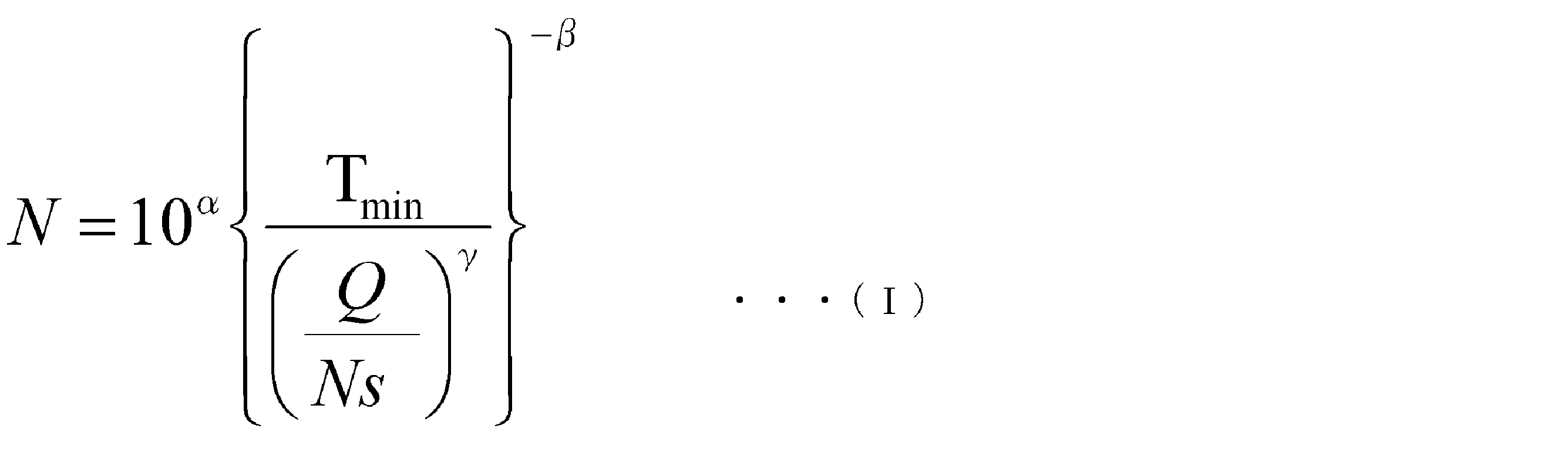
- 前記熱可塑性樹脂と前記ガラス繊維束とを混練するためのスクリューエレメントの外径を変更したとき、前記数式(I)が下記の数式(II)である請求項1に記載のシミュレーション装置。

- 前記製造条件算出手段は、
複数の前記L/Dの条件毎に、吐出量Qと前記最小せん断応力履歴値Tminとの関係を表す近似曲線を作成する近似曲線作成ステップと、
前記数式(I)に基づいて、前記単位量あたりのペレット数Nが所定の値以下になる最小せん断応力履歴値Tminである閾値Tmin決定する閾値Tmin決定ステップと、
各近似曲線から前記閾値Tminでの各吐出量Qnを算出する吐出量Qn算出ステップと、
前記L/Dと前記Qnとの間の関係式を導出する関係式導出ステップと、を備え、
前記関係式に基づいて、製造条件を選択するする請求項1又は2に記載のシミュレーション装置。 - 前記スクリューエレメントは、フライト部に切り欠きを有する逆送りのスクリューエレメントである請求項1から3のいずれかに記載のシミュレーション装置。
- 請求項1から4のいずれかに記載のシミュレーション装置の機能をコンピュータで実現するためのプログラム。
- 請求項5に記載のプログラムを記録したコンピュータ読み取り可能な記録媒体。
Priority Applications (2)
| Application Number | Priority Date | Filing Date | Title |
|---|---|---|---|
| EP11819736.7A EP2610041A4 (en) | 2010-08-27 | 2011-07-27 | SIMULATION DEVICE, PROGRAM, AND RECORDING MEDIUM |
| US13/818,342 US20140149089A1 (en) | 2010-08-27 | 2011-07-27 | Simulation device, program, and recording medium |
Applications Claiming Priority (2)
| Application Number | Priority Date | Filing Date | Title |
|---|---|---|---|
| JP2010191542A JP5632236B2 (ja) | 2010-08-27 | 2010-08-27 | シミュレーション装置、プログラム、及び記録媒体 |
| JP2010-191542 | 2010-08-27 |
Publications (1)
| Publication Number | Publication Date |
|---|---|
| WO2012026271A1 true WO2012026271A1 (ja) | 2012-03-01 |
Family
ID=45723279
Family Applications (1)
| Application Number | Title | Priority Date | Filing Date |
|---|---|---|---|
| PCT/JP2011/067120 Ceased WO2012026271A1 (ja) | 2010-08-27 | 2011-07-27 | シミュレーション装置、プログラム、及び記録媒体 |
Country Status (5)
| Country | Link |
|---|---|
| US (1) | US20140149089A1 (ja) |
| EP (1) | EP2610041A4 (ja) |
| JP (1) | JP5632236B2 (ja) |
| TW (1) | TW201214182A (ja) |
| WO (1) | WO2012026271A1 (ja) |
Cited By (1)
| Publication number | Priority date | Publication date | Assignee | Title |
|---|---|---|---|---|
| CN114474462A (zh) * | 2020-10-26 | 2022-05-13 | 株式会社神户制钢所 | 机器学习方法、机器学习装置以及机器学习程序 |
Families Citing this family (4)
| Publication number | Priority date | Publication date | Assignee | Title |
|---|---|---|---|---|
| JP5973251B2 (ja) * | 2012-06-20 | 2016-08-23 | ポリプラスチックス株式会社 | ガラス繊維長分布導出装置、ガラス繊維分布導出用プログラム、及びガラス繊維分布導出用記録媒体 |
| JP6198666B2 (ja) | 2014-04-22 | 2017-09-20 | 宏平 澤 | 混練装置 |
| JP6773824B2 (ja) * | 2019-01-25 | 2020-10-21 | ポリプラスチックス株式会社 | 複合成形品 |
| JP7411509B2 (ja) * | 2020-06-15 | 2024-01-11 | 株式会社日本製鋼所 | シミュレーション装置、シミュレーション方法及びシミュレーションプログラム |
Citations (8)
| Publication number | Priority date | Publication date | Assignee | Title |
|---|---|---|---|---|
| JPH07137113A (ja) * | 1993-11-15 | 1995-05-30 | Sekisui Chem Co Ltd | 2軸押出機のスクリュー設計方法 |
| JPH0860001A (ja) * | 1994-06-14 | 1996-03-05 | Toray Ind Inc | 繊維強化熱可塑性樹脂ペレットおよびその製造方法 |
| JPH0929819A (ja) * | 1995-07-20 | 1997-02-04 | Asahi Chem Ind Co Ltd | 押出機運転シミュレーションシステム |
| JPH11512666A (ja) | 1995-09-29 | 1999-11-02 | クルップ ヴェルナー ウント プライデラー ゲゼルシャフト ミット ベシュレンクテル ハフツング | 同じ向きに回転するしっかりと噛み合う押し出し機での連続調製プロセス実行の方法 |
| JP2002018842A (ja) * | 2000-07-10 | 2002-01-22 | Sumitomo Chem Co Ltd | 液晶性樹脂ペレットの製造方法 |
| JP2002120271A (ja) | 2000-10-13 | 2002-04-23 | Japan Steel Works Ltd:The | スクリュ式二軸混練押出機用スクリュ |
| WO2006123824A1 (ja) * | 2005-05-18 | 2006-11-23 | Polyplastics Co., Ltd. | 繊維状充填剤高濃度配合樹脂組成物の製造方法及び樹脂組成物ペレット |
| JP2010000654A (ja) * | 2008-06-19 | 2010-01-07 | Japan Steel Works Ltd:The | 繊維強化樹脂ペレットの製造方法及び装置 |
Family Cites Families (4)
| Publication number | Priority date | Publication date | Assignee | Title |
|---|---|---|---|---|
| US7208219B2 (en) * | 1997-12-18 | 2007-04-24 | Lrm Industries, Llc | Thermoplastic molding process and apparatus |
| JP2002220538A (ja) * | 2000-03-28 | 2002-08-09 | Mazda Motor Corp | 成形用ガラス長繊維強化樹脂材料、該樹脂材料を射出成形してなる射出成形品及び該樹脂材料を用いた成形方法 |
| WO2005099984A1 (ja) * | 2004-04-15 | 2005-10-27 | Polyplastics Co., Ltd. | 繊維状充填剤の長さが制御された樹脂組成物ペレットの製造方法 |
| JP4602024B2 (ja) * | 2004-07-28 | 2010-12-22 | ポリプラスチックス株式会社 | 液晶性樹脂組成物の製造方法 |
-
2010
- 2010-08-27 JP JP2010191542A patent/JP5632236B2/ja active Active
-
2011
- 2011-07-27 EP EP11819736.7A patent/EP2610041A4/en not_active Withdrawn
- 2011-07-27 WO PCT/JP2011/067120 patent/WO2012026271A1/ja not_active Ceased
- 2011-07-27 US US13/818,342 patent/US20140149089A1/en not_active Abandoned
- 2011-08-01 TW TW100127171A patent/TW201214182A/zh unknown
Patent Citations (8)
| Publication number | Priority date | Publication date | Assignee | Title |
|---|---|---|---|---|
| JPH07137113A (ja) * | 1993-11-15 | 1995-05-30 | Sekisui Chem Co Ltd | 2軸押出機のスクリュー設計方法 |
| JPH0860001A (ja) * | 1994-06-14 | 1996-03-05 | Toray Ind Inc | 繊維強化熱可塑性樹脂ペレットおよびその製造方法 |
| JPH0929819A (ja) * | 1995-07-20 | 1997-02-04 | Asahi Chem Ind Co Ltd | 押出機運転シミュレーションシステム |
| JPH11512666A (ja) | 1995-09-29 | 1999-11-02 | クルップ ヴェルナー ウント プライデラー ゲゼルシャフト ミット ベシュレンクテル ハフツング | 同じ向きに回転するしっかりと噛み合う押し出し機での連続調製プロセス実行の方法 |
| JP2002018842A (ja) * | 2000-07-10 | 2002-01-22 | Sumitomo Chem Co Ltd | 液晶性樹脂ペレットの製造方法 |
| JP2002120271A (ja) | 2000-10-13 | 2002-04-23 | Japan Steel Works Ltd:The | スクリュ式二軸混練押出機用スクリュ |
| WO2006123824A1 (ja) * | 2005-05-18 | 2006-11-23 | Polyplastics Co., Ltd. | 繊維状充填剤高濃度配合樹脂組成物の製造方法及び樹脂組成物ペレット |
| JP2010000654A (ja) * | 2008-06-19 | 2010-01-07 | Japan Steel Works Ltd:The | 繊維強化樹脂ペレットの製造方法及び装置 |
Non-Patent Citations (2)
| Title |
|---|
| See also references of EP2610041A4 |
| SEIKEI KAKOU, vol. 11, no. 11, 1999, pages 910 - 913 |
Cited By (1)
| Publication number | Priority date | Publication date | Assignee | Title |
|---|---|---|---|---|
| CN114474462A (zh) * | 2020-10-26 | 2022-05-13 | 株式会社神户制钢所 | 机器学习方法、机器学习装置以及机器学习程序 |
Also Published As
| Publication number | Publication date |
|---|---|
| EP2610041A4 (en) | 2014-06-18 |
| TW201214182A (en) | 2012-04-01 |
| JP2012045866A (ja) | 2012-03-08 |
| EP2610041A1 (en) | 2013-07-03 |
| US20140149089A1 (en) | 2014-05-29 |
| JP5632236B2 (ja) | 2014-11-26 |
Similar Documents
| Publication | Publication Date | Title |
|---|---|---|
| JP5536705B2 (ja) | ガラス繊維強化熱可塑性樹脂組成物ペレットの製造方法 | |
| JP5632235B2 (ja) | ガラス繊維強化熱可塑性樹脂組成物ペレットの製造方法 | |
| JP5632236B2 (ja) | シミュレーション装置、プログラム、及び記録媒体 | |
| US20190337211A1 (en) | Distributive and dispersive mixing devices | |
| Lindt | Pressure development in the melting zone of a single‐screw extruder | |
| US7156550B2 (en) | Apparatus for plasticating thermoplastic resin including polypropylene | |
| CN205238526U (zh) | 一种用于生产塑料加工助剂母粒的同向平行双螺杆 | |
| Bai et al. | A new type of 3D printing molding equipment: overall structural design and the numerical simulation for the flow field characteristics of its screw module | |
| JP5973251B2 (ja) | ガラス繊維長分布導出装置、ガラス繊維分布導出用プログラム、及びガラス繊維分布導出用記録媒体 | |
| Leister et al. | Twin-screw extruders for pharmaceutical hot-melt extrusion: technology, techniques and practices | |
| JP5536704B2 (ja) | ガラス繊維強化熱可塑性樹脂組成物ペレットの製造方法 | |
| Wilczyński et al. | Experimental study of melting of LDPE/PS polyblend in an intermeshing counter‐rotating twin screw extruder | |
| JP7125604B2 (ja) | 強化樹脂成形体の製造装置及び製造方法 | |
| Dörner et al. | Analysis of the advantageous process and mixing behaviour of wave-dispersion screws in single screw extrusion | |
| Abdel-Ghany et al. | Effect of Geometry and Rotational Speed on the Axial Pressure Profile of a Single Screw Extrusion | |
| CN204505776U (zh) | 一种挤出机 | |
| CN204505770U (zh) | 一种单螺杆的挤出机 | |
| CN101983121A (zh) | 挤压机和用于挤压聚合物的方法 | |
| CN218557913U (zh) | 一种用于bfs的挤出螺杆 | |
| Loukus et al. | Elongational flow in multiple screw extruders | |
| Selvasankar | Modeling and characterization of conical and parallel co-rotating twin screw extruders | |
| CN201745153U (zh) | 一种制造珠光色母粒产品的双螺杆挤出机 | |
| JP2023079184A (ja) | 熱可塑性樹脂組成物の成形品の成形機、および成形品の製造方法 |
Legal Events
| Date | Code | Title | Description |
|---|---|---|---|
| 121 | Ep: the epo has been informed by wipo that ep was designated in this application |
Ref document number: 11819736 Country of ref document: EP Kind code of ref document: A1 |
|
| WWE | Wipo information: entry into national phase |
Ref document number: 2011819736 Country of ref document: EP |
|
| NENP | Non-entry into the national phase |
Ref country code: DE |
|
| WWE | Wipo information: entry into national phase |
Ref document number: 13818342 Country of ref document: US |