WO2012026514A1 - 参照電極 - Google Patents
参照電極 Download PDFInfo
- Publication number
- WO2012026514A1 WO2012026514A1 PCT/JP2011/069142 JP2011069142W WO2012026514A1 WO 2012026514 A1 WO2012026514 A1 WO 2012026514A1 JP 2011069142 W JP2011069142 W JP 2011069142W WO 2012026514 A1 WO2012026514 A1 WO 2012026514A1
- Authority
- WO
- WIPO (PCT)
- Prior art keywords
- layer
- ionic liquid
- hydrophobic ionic
- constituting
- liquid
- Prior art date
- Legal status (The legal status is an assumption and is not a legal conclusion. Google has not performed a legal analysis and makes no representation as to the accuracy of the status listed.)
- Ceased
Links
Images


Classifications
-
- G—PHYSICS
- G01—MEASURING; TESTING
- G01N—INVESTIGATING OR ANALYSING MATERIALS BY DETERMINING THEIR CHEMICAL OR PHYSICAL PROPERTIES
- G01N27/00—Investigating or analysing materials by the use of electric, electrochemical, or magnetic means
- G01N27/26—Investigating or analysing materials by the use of electric, electrochemical, or magnetic means by investigating electrochemical variables; by using electrolysis or electrophoresis
- G01N27/28—Electrolytic cell components
- G01N27/30—Electrodes, e.g. test electrodes; Half-cells
- G01N27/301—Reference electrodes
-
- G—PHYSICS
- G01—MEASURING; TESTING
- G01N—INVESTIGATING OR ANALYSING MATERIALS BY DETERMINING THEIR CHEMICAL OR PHYSICAL PROPERTIES
- G01N27/00—Investigating or analysing materials by the use of electric, electrochemical, or magnetic means
- G01N27/26—Investigating or analysing materials by the use of electric, electrochemical, or magnetic means by investigating electrochemical variables; by using electrolysis or electrophoresis
- G01N27/28—Electrolytic cell components
- G01N27/30—Electrodes, e.g. test electrodes; Half-cells
- G01N27/302—Electrodes, e.g. test electrodes; Half-cells pH sensitive, e.g. quinhydron, antimony or hydrogen electrodes
Definitions
- the present invention relates to a reference electrode serving as a standard for calculation of electrode potential and electrochemical measurement.
- An internal electrode used for presenting a constant reference potential in pH measurement or the like is, for example, an internal electrode made of silver / silver chloride or the like immersed in an internal solution made of a high-concentration KCl solution. Some of them are configured to come into contact with a sample liquid through a liquid junction made of a porous member.
- the present applicant has applied for a reference electrode configured as a salt bridge (see Patent Documents 1 and 2).
- the hydrophobic ionic liquid gel to include a large amount of ionic liquid.
- the hydrophobic ionic liquid gel alone can keep the shape.
- Increasing the thickness and size of the gel while maintaining a certain degree of hardness is very difficult in terms of manufacturing technology and requires a large cost.
- the present invention has been made in view of the problems as described above, and it is not necessary to use a gelled hydrophobic ionic liquid having a predetermined hardness or viscosity that is difficult to manufacture and having a large thickness and the like. It is an object of the present invention to provide a reference electrode that can improve the product life.
- the reference electrode of the present invention is a reference electrode including a housing body that houses an internal electrode and a filler that electrically connects the internal electrode and the sample liquid, and the internal electrode and the sample
- the filler forms a layer between an opening provided in the container for contacting the liquid and the filler, and the filler is made of a water-soluble electrolyte solution, and the internal electrode
- hydrophobic ionic liquid which will be described in detail later, comprises a combination of an organic or inorganic cation and an organic or inorganic anion, has a melting point of 100 ° C. or less, and has a solubility in water of several mM (mmol / Dm 3 ) or less hydrophobic salt is mainly meant.
- the ionic liquid is also called an ionic liquid or a normally dissolved salt.
- the “reference electrode” is synonymous with a reference electrode, a verification electrode, a reference electrode, and a comparison electrode.
- solution and “liquid” are not only ordinary liquids, but also include not only ordinary liquids but also gelled and flowing states and states that can maintain a shape. is there.
- the gel of the hydrophobic ionic liquid constituting the third layer does not need to be formed thick, and can be formed with a thickness that can be easily manufactured while maintaining a predetermined hardness.
- the gelled hydrophobic ionic liquid can block the opening and can be used in a minimum amount that can maintain the sealing function. Well, it is not necessary to increase the thickness.
- the hydrophobic ionic liquid constituting the second layer is covered with the third layer in the container, it is not necessary to maintain the shape of the second layer alone, and the liquid or hardness A small gel-like hydrophobic ionic liquid can be used. That is, the second layer can be formed of a liquid that is easy to manufacture or a gel-like hydrophobic ionic liquid with low hardness, and the third layer can be easily filled with an amount necessary to replenish ions.
- the first layer is composed of a water-soluble electrolyte solution and the second layer is composed of a hydrophobic ionic liquid, the first layer and the second layer do not dissolve in each other and are mixed. Even if it is, it can be separated naturally.
- the first layer is constituted.
- the water-soluble electrolyte solution to be used may be a gelled one.
- the water solution constituting the first layer can be used.
- the viscosity of the aqueous electrolyte solution may be 100 mPa ⁇ s or more so as not to become an emulsion.
- the hydrophobic ionic liquid constituting the second layer should be a liquid that is not gelled. That's fine.
- the hydrophobic ionic liquid constituting the second layer is gelled. Furthermore, considering the ease of manufacturing, the hardness or viscosity of the hydrophobic ionic liquid of the second layer may be smaller than the hardness or viscosity of the hydrophobic ionic liquid of the third layer.
- the viscosity of the hydrophobic ionic liquid constituting the second layer may be 100 mPa ⁇ s or more and 1000 mPa ⁇ s or less.
- the specific gravity of the water-soluble electrolyte solution constituting the first layer is Any material that is lighter than the specific gravity of the hydrophobic ionic liquid constituting the second layer may be used.
- the opening is more external than the inner side of the container.
- the side should just be formed small.
- the viscosity of the hydrophobic ionic liquid constituting the third layer is 1000 mPa ⁇ s or more. Good.
- the reference electrode according to another aspect of the present invention is a reference electrode including a housing body that houses an internal electrode and a filler that electrically connects the internal electrode and the sample liquid, and the internal electrode
- the filler forms a layer between the sample liquid and the opening provided in the container for contacting the filler, and the filler is made of a water-soluble electrolyte solution.
- hydrophobic ionic liquid which will be described in detail later, comprises a combination of an organic or inorganic cation and an organic or inorganic anion, has a melting point of 100 ° C. or less, and has a solubility in water of several mM (mmol / Dm 3 ) or less hydrophobic salt is mainly meant.
- the ionic liquid is also called an ionic liquid or a normally dissolved salt.
- the “reference electrode” is synonymous with a reference electrode, a verification electrode, a reference electrode, and a comparison electrode.
- solution and “liquid” are not only ordinary liquids, but also include not only ordinary liquids but also gelled and flowing states and states that can maintain a shape. is there.
- the porous material which comprises the 3rd layer since the porous material which comprises the 3rd layer is contacting the sample liquid and the hydrophobic ionic liquid of the 2nd layer does not contact the sample liquid directly, it comprises a hydrophobic ionic liquid. It is possible to suppress ions from flowing into the sample liquid. Further, since the second layer is covered by the third layer, it is not necessary to gel the hydrophobic ionic liquid of the second layer in order to maintain the shape. Accordingly, it is possible to eliminate the use of gelled hydrophobic ions, thereby eliminating the problem that the sealing function is lowered due to the thinning and thinning of the gel and the product life is shortened.
- the first layer is composed of a water-soluble electrolyte solution and the second layer is composed of a hydrophobic ionic liquid, the first layer and the second layer do not dissolve in each other and are mixed. Even if it is, it can be separated naturally.
- the first layer is constituted.
- the water-soluble electrolyte solution to be used may be a gelled one.
- the water solution constituting the first layer can be used. It is sufficient that the viscosity of the aqueous electrolyte solution is suppressed to become an emulsion, for example, 20 mPa ⁇ s, more preferably 100 mPa ⁇ s or more.
- the hydrophobic ionic liquid constituting the second layer may be a liquid that is not gelled.
- the hydrophobic ionic liquid constituting the second layer may be a gelled liquid. Furthermore, considering the ease of manufacturing, the hardness or viscosity of the hydrophobic ionic liquid of the second layer may be smaller than the hardness or viscosity of the hydrophobic ionic liquid of the third layer.
- the hydrophobicity constituting the second layer is described as follows.
- the viscosity of the ionic liquid may be 300 mPa ⁇ s or more and 1000 mPa ⁇ s or less.
- the specific gravity of the water-soluble electrolyte solution constituting the first layer is As long as it is lighter than the specific gravity of the hydrophobic ionic liquid constituting the second layer.
- the porous material constituting the third layer In order to prevent the hydrophobic ionic liquid itself constituting the second layer from passing through the porous material constituting the third layer and flowing out directly into the sample liquid, the porous material constituting the third layer May be hydrophilic. If it is such, since it is a hydrophobic ionic liquid that comprises the 2nd layer, it will be repelled on the surface of a hydrophilic porous material, and it can prevent passing a 3rd layer. .
- the diameter of the pores of the porous material constituting the third layer is such that the hydrophobic ionic liquid constituting the second layer It is sufficient if the size is such that cannot enter.
- the pore diameter of the porous material constituting the third layer may be in the range of 100 nm to 100 ⁇ m.
- porous material examples include those in which the porous material constituting the third layer is polycarbonate.
- the second layer functions as a buffer and is appropriately replenished with ions. Therefore, the gel of the third layer can be prevented from thinning. Therefore, even if the third layer is thin, there is no problem, and it is not necessary to form a hard and thick hydrophobic ionic liquid gel. Therefore, the third layer can be very easily manufactured. Furthermore, since the sealing function by the hydrophobic ionic liquid is maintained, the product life can be extended compared to the conventional case, and the state in which the fluctuation of the reference potential can be prevented can be maintained for a long time.
- the porous material constituting the third layer is configured so that the hydrophobic ionic liquid constituting the second layer and the sample liquid do not directly contact each other. Therefore, it is possible to prevent ions constituting the hydrophobic ionic liquid from flowing out into the sample liquid.
- the hydrophobic ionic liquid of the second layer may be a liquid or a gel having a low hardness that is easy to manufacture. That is, the gelled hydrophobic ionic liquid can not be used, and the problem that the gel of the hydrophobic ionic liquid is thinned and the product life is shortened can be eliminated.
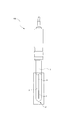
- FIG. 1 is a schematic view showing a reference electrode according to the first embodiment of the present invention.
- FIG. 2 is a schematic cross-sectional view showing the internal structure at the tip of the support tube in the same embodiment.
- FIG. 3 is a schematic cross-sectional view showing the internal structure of the support tube tip in another embodiment of the first embodiment.
- FIG. 4 is a schematic cross-sectional view showing the internal structure of the support tube tip in yet another embodiment of the first embodiment.
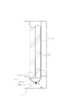
- FIG. 5 is a schematic view showing a reference electrode according to the second embodiment of the present invention.
- FIG. 6 is a schematic view showing a reference electrode according to the third embodiment of the present invention.
- FIG. 7 is a schematic cross-sectional view showing the internal structure at the tip of the support tube in the third embodiment.
- FIG. 8 is a schematic cross-sectional view showing the internal structure at the tip of the support tube in a modified embodiment of the third embodiment.
- FIG. 9 is a schematic cross-sectional view showing the internal structure at the tip of the support tube in a modified embodiment of the third embodiment.
- the reference electrode 100 is a substantially cylindrical glass support tube 3 (of the present invention). Equivalent to a container).
- the support tube 3 contains an internal electrode 1 and is filled with a filler 2 that electrically connects the internal electrode 1 and the sample liquid 4.
- a lead wire 11 is connected to the internal electrode 1, and the lead wire 11 extends outside from the base end portion of the support tube 3 and is connected to a measuring device (not shown).
- the support tube 3 has an opening 31 formed at its tip so that the sample liquid 4 and the filler 2 can come into contact with each other. It is smaller than the end side.
- the internal electrode 1 is, for example, an Ag / AgCl electrode, and is configured by covering the internal silver with silver chloride.
- an Hg / Hg 2 Cl 2 electrode or an Hg / Hg 2 SO 4 electrode may be used.
- the filler 2 is filled so as to form a plurality of layers between the internal electrode 1 and the opening 31 at the tip of the support tube 3 as shown in FIG. More specifically, the filler 2 is made of a water-soluble electrolyte solution, and is formed of a first layer 21 formed so as to be in contact with the internal electrode 1, a hydrophobic ionic liquid, and the first layer 21.
- the second layer 22 formed so as to be in contact with the third layer 23 made of a gelled hydrophobic ionic liquid, which is in contact with the second layer 22 and formed in the opening 31. is there.
- the water-soluble electrolyte solution constituting the first layer 21 is, for example, a KCl solution.
- aqueous electrolyte solution when the inner electrode 1 is made of Ag / AgCl is Cl - can be used to include, but unless they enter into the hydrophobic ionic liquid of the second layer 22 to be described later.
- the hydrophobic ionic liquid of the second layer described later functions as a salt bridge, generation of an inter-liquid potential can be suppressed.
- a NaCl solution or the like may be used.
- Cl - and it an electrolyte solution consisting of the same cation as the cation of the hydrophobic ionic liquid or the like to be described later. This is because the same ions as those constituting the hydrophobic ionic liquid are not particularly problematic even if they enter from the electrolyte solution.
- the KCl solution is gelled, and always covers the internal electrode 1 and is provided with at least the periphery of the internal electrode 1 with a viscosity sufficient to seal the inside of the support tube 3 around it.
- the method for gelling the water-soluble electrolyte solution is not particularly limited.
- a method using a polymer such as The viscosity of the gel is adjusted by adjusting the mixing ratio of the water-soluble electrolyte solution and the polymer. More specifically, the viscosity of the water-soluble electrolyte solution constituting the first layer 21 is 100 mPa ⁇ s or more.
- the cation is at least one of a quaternary ammonium cation, a quaternary phosphonium cation, and a quaternary arzonium cation, and the anion is [R 1 SO 2 NSO 2 R 2 ] ⁇ (wherein R 1 and R 2 are perfluoroalkyl groups having 1 to 5 carbon atoms), borate ions containing fluorine and tetravalent boron, bis (2-ethylhexyl) sulfosuccinate, AlCl 4 ⁇ , Al 3 Cl 7 ⁇ , NO 3 ⁇ , BF 4 ⁇ , PF 6 ⁇ , CH 3 COO ⁇ , CF 3 COO ⁇ , CF 3 SO 3 ⁇ , (CF 3 SO 2 ) 2 N ⁇ , (CF 3 SO 2 ) 3 C -, AsF 6 - , SbF 6 -, F (HF)
- the hydrophobic ionic liquid constituting the second layer 22 is a liquid that is not gelled, and can be easily manufactured even if the thickness of the second layer 22 is large.
- the specific gravity of the electrolyte solution constituting the first layer 21 is made lighter than the specific gravity of the hydrophobic ionic liquid constituting the second layer 22.
- the third layer 23 is a gelling film of a hydrophobic ionic liquid provided so as to close the opening 31, and has the same composition as the hydrophobic ionic liquid of the second layer 22.
- the third layer 23 functions as a salt bridge together with the second layer 22 and exhibits a sealing function so that the sample liquid 4 does not directly contact the inside of the support tube 3 by the third layer 23.
- the method of gelling the hydrophobic ionic liquid is the same as the method of gelling the water-soluble electrolyte solution described above, and the viscosity of the hydrophobic ionic liquid is the same as that of the first layer 21 and the second layer 22 even if the weight is added.
- the three layers 23 are prevented from coming off. More specifically, the viscosity of the hydrophobic ionic liquid constituting the third layer 23 is set to 1000 mPa ⁇ s or more.
- the second layer The hydrophobic ionic liquid constituting 22 functions as a buffer and is replenished with ions. Accordingly, since the gel can be prevented from shrinking due to the outflow of constituent ions, the product life can be extended without producing a hard gel-like hydrophobic ionic liquid having a large thickness which is difficult to manufacture. That is, it is not necessary to form the hydrophobic ionic liquid gel constituting the third layer 23 thick, and the gel can be formed to a thickness that can be easily manufactured while maintaining a predetermined hardness.
- the gel film of the hydrophobic ionic liquid can be made thin enough to be easily manufactured.
- the second layer 22 since the third layer 23 is gelled so as to close the opening 31 and is covered, the second layer 22 does not need to maintain its own shape, and the second layer 22
- the hydrophobic ionic liquid constituting the layer 22 can be a liquid. That is, since it is not necessary to make it hard, even if the thickness of the second layer 22 is increased, the second layer 22 can be easily manufactured at low cost and the amount sufficient to function as a buffer for the third layer 23 for a long period of time. it can.
- the first layer 21 is composed of a water-soluble electrolyte solution and the second layer 22 is composed of a hydrophobic ionic liquid, the first layer 21 and the second layer 22 may be dissolved together.
- the first layer 21 is lighter in specific gravity than the second layer 22 even if it is mixed, and the order of the layers can be restored simply by raising the reference electrode 100. Can be returned to.
- the water-soluble electrolyte solution constituting the first layer 21 is gelled so that there is no gap in the support tube 3, even when the reference electrode 100 is turned sideways, It is possible to prevent the second layer 22 from being mixed.
- the hydrophobic ionic liquid constituting the second layer is in a non-gelled liquid state, but may be gelled. In this case, it is preferable that the gel is looser than the hardness of the gel of the hydrophobic ionic liquid constituting the third layer to facilitate the production.
- the specific viscosity of the hydrophobic ionic liquid constituting the second layer may be in the range of 100 mPa ⁇ s to 1000 mPa ⁇ s.
- the water-soluble electrolyte solution constituting the first layer is gelled, but it may be liquid.
- the water-soluble electrolyte solution or ionic liquid when the water-soluble electrolyte solution or ionic liquid is in a non-gelled liquid state, for example, each liquid and the polymer for gelation are not mixed, or only a small amount of polymer is mixed. Even if it has been made, it is possible to mention a state in which there is substantially no change in viscosity or the like.
- the loose gel state includes, for example, a state in which a water-soluble electrolyte solution or an ionic liquid cannot maintain a single shape and has a higher viscosity than a liquid state that is not gelled.
- the third layer is provided so as to block only the protruding portion at the tip of the support tube.
- the thickness of the layer may be further increased to the inner side within a range in which manufacture is easy.
- the third layer 23 is a gel having a thin plate-like central portion slightly protruded, a place where the third layer 23 is caught on the support tube is created.
- the three layers 23 can be more difficult to drop off from the opening 31.
- the third layer 23 may be easily held by providing a porous material in the opening 21 and containing a gelled hydrophobic ionic liquid in the pores.
- the opening 31 of the first embodiment has a hole formed straight, but for example, as shown in FIG.
- the inner opening diameter may be set larger than the distal end opening diameter. Even in such a case, it is possible to easily prevent the gelled hydrophobic ionic liquid constituting the third layer from falling off.
- the thicknesses of the first layer and the second layer can be appropriately changed.
- the internal electrode may be in contact with the first layer and the second layer.
- the reference voltage may be prevented from fluctuating using a correction means such as temperature compensation.
- the reference electrode 100 includes a cylindrical support tube 3 (corresponding to the housing portion of the present invention), and an opening 31 provided at the tip of the support tube 3. And a filling material 2 for electrically connecting the internal electrode 1 and the sample liquid 4 is filled therein.
- the filler 2 is layered, and in particular, the porous material film constituting the third layer 23 provided in the opening 31 is fixed to the support tube 3 by the film fixing part 32.
- the support tube 3 accommodates the internal electrode 1 and the filler 2 and includes PP, PE, acrylic, PTFE (tetrafluoroethylene resin), PVDF (vinylidene fluoride resin), PEEK (polyethylene).
- a resin such as an ether / ether / ketone resin), glass, metal, ceramic, or the like is conceivable. In this embodiment, it shape
- a seal packing 33 that comes into liquid-tight contact with the base end portion so that the filler 2 does not leak out of the support tube 3, and a cap 34 that covers the seal packing 33. Is provided.
- tip part of the support tube 3 is small,
- the external thread part 32a is provided in the outer peripheral surface of the front-end
- the internal thread part is formed in the said internal thread part 32a and a substantially cylindrical inner peripheral surface.
- the film fixing part 32 in which the part is formed is screwed.
- an accommodation groove for accommodating the O-ring 35 is provided on the distal end surface of the distal end portion concentrically with the central axis of the support tube 3.
- membrane by the porous material which is the 3rd layer 23 is provided so that the front end surface may be covered.
- the internal electrode 1 is, for example, an Ag / AgCl electrode, and is configured by covering the internal silver with silver chloride.
- an Hg / Hg 2 Cl 2 electrode or an Hg / Hg 2 SO 4 electrode may be used.
- the filler 2 is filled so as to form a plurality of layers between the internal electrode 1 and the opening 31 at the tip of the support tube 3 as shown in FIG. More specifically, the filler 2 is made of a water-soluble electrolyte solution, and is formed of a first layer 21 formed so as to be in contact with the internal electrode 1, a hydrophobic ionic liquid, and the first layer 21.
- the second layer 22 formed so as to be in contact with the third layer 23 made of a gelled hydrophobic ionic liquid, which is in contact with the second layer 22 and formed in the opening 31. is there.
- the water-soluble electrolyte solution constituting the first layer 21 is, for example, a KCl solution.
- aqueous electrolyte solution when the inner electrode 1 is made of Ag / AgCl is Cl - can be used to include, but unless they enter into the hydrophobic ionic liquid of the second layer 22 to be described later. Further, since the hydrophobic ionic liquid of the second layer described later functions as a salt bridge, the generation of an inter-liquid potential can be suppressed, and for example, a NaCl solution or the like can be used. Furthermore, Cl - and it may be used an electrolyte solution consisting of the same cation as the cation of the hydrophobic ionic liquid or the like to be described later. This is because the same ions as those constituting the hydrophobic ionic liquid are not particularly problematic even if they enter from the electrolyte solution.
- This KCl solution is gelled, and always covers the internal electrode 1 and is provided at least around the internal electrode 1 with a viscosity sufficient to seal the inside of the surrounding support tube 3.
- the method for gelling the water-soluble electrolyte solution is not particularly limited.
- a method using a polymer such as The viscosity of the gel is adjusted by adjusting the mixing ratio of the water-soluble electrolyte solution and the polymer.
- the viscosity of the water-soluble electrolyte solution constituting the first layer 21 is set to an extent that suppresses the formation of an emulsion, for example, 20 mPa ⁇ s, more preferably 100 mPa ⁇ s or more.
- the cation is at least one of a quaternary ammonium cation, a quaternary phosphonium cation, and a quaternary arzonium cation, and the anion is [R 1 SO 2 NSO 2 R 2 ] ⁇ (wherein R 1 and R 2 are perfluoroalkyl groups having 1 to 5 carbon atoms), borate ions containing fluorine and tetravalent boron, bis (2-ethylhexyl) sulfosuccinate, AlCl 4 ⁇ , Al 3 Cl 7 ⁇ , NO 3 ⁇ , BF 4 ⁇ , PF 6 ⁇ , CH 3 COO ⁇ , CF 3 COO ⁇ , CF 3 SO 3 ⁇ , (CF 3 SO 2 ) 2 N ⁇ , (CF 3 SO 2 ) 3 C -, AsF 6 - , SbF 6 -, F (HF)
- the hydrophobic ionic liquid constituting the second layer 22 is a liquid that is not gelled, and can be easily manufactured even if the thickness of the second layer 22 is large. Further, the specific gravity of the electrolyte solution constituting the first layer 21 is lighter than the specific gravity of the hydrophobic ionic liquid constituting the second layer 22.
- the third layer 23 is provided so as to close the opening 31, and is made of a porous film with polycarbonate.
- This porous membrane is hydrophilic and contains moisture in the sample liquid 4, but the hydrophobic ionic liquid is repelled on the surface.
- the pore diameter of the porous membrane is set to about 100 nm to 100 ⁇ m so that the hydrophobic ionic liquid constituting the second layer 22 cannot enter the inside of the porous membrane due to surface tension or the like.
- the viscosity of the hydrophobic ionic liquid may be set higher as the pore diameter is larger so that the surface tension or the like can be easily applied.
- the porous film constituting the third layer 23 is in contact with the sample liquid 4, and the hydrophobic ionic liquid of the second layer 22 does not directly contact the sample liquid. Therefore, ions constituting the hydrophobic ionic liquid can be prevented from flowing out into the sample liquid 4. Further, since the second layer 22 is covered with the third layer 23 in the support tube 3, the hydrophobic ionic liquid does not need to be gelled in order to maintain the shape. Accordingly, the gelled hydrophobic ionic liquid can be prevented from being used for the reference electrode 100, and the problem that the sealing function is lowered and the product life is shortened due to the thinning and thinning of the gel can be eliminated. it can.
- the first layer 21 is composed of a water-soluble electrolyte solution and the second layer 22 is composed of a hydrophobic ionic liquid, the first layer 21 and the second layer 22 may be dissolved together.
- the first layer 21 is lighter in specific gravity than the second layer 22 even if it is mixed, and the order of the layers can be restored simply by raising the reference electrode 100. Can be returned to.
- the water-soluble electrolyte solution constituting the first layer 21 is gelled so that there is no gap in the support tube 3, even when the reference electrode 100 is turned sideways, It is possible to prevent the second layer 22 from being mixed.
- the third-layer porous membrane is fixed by being sandwiched between the support tube body and the membrane fixing portion 33, but may be provided in the opening 31 by other methods.
- the porous membrane may be heat-sealed so as to cover the tip of the membrane fixing portion 33.
- a porous film may be heat-sealed at the tip of the main body of the support tube 3.
- the hydrophobic ionic liquid constituting the second layer is in a non-gelled liquid state, but may be gelled. In this case, it is preferable that the gel is made loose to facilitate the production.
- the specific viscosity of the hydrophobic ionic liquid constituting the second layer may be in the range of 300 mPa ⁇ s to 1000 mPa ⁇ s. By gelling the second layer in such a range, it is easy to manufacture and it is also possible to prevent the first layer and the second layer from being mixed.
- the hydrophobic ionic liquid may be gelled by the same method as the gelation of the water-soluble electrolyte solution described above.
- the water-soluble electrolyte solution constituting the first layer is gelled, but it may be liquid.
- the multi-pinhole reference electrode 100 may be different from that of the above embodiment. More specifically, the reference electrode 100 of the third embodiment is a glass support tube having a substantially cylindrical shape, as shown in the external view of FIG. 6 and the enlarged view of the sample liquid 4 in FIG. 3 (corresponding to the container of the present invention).
- the support tube 3 contains an internal electrode 1 and is filled with a filler 2 that electrically connects the internal electrode 1 and the sample liquid 4.
- a lead wire 11 is connected to the internal electrode 1, and the lead wire 11 extends outside from the base end portion of the support tube 3 and is connected to a measuring device (not shown).
- the support tube 3 has an opening 31 formed at its tip so that the sample liquid 4 and the filler 2 can come into contact with each other. It is smaller than the end side.
- the third layer is provided so as to block only the protruding portion at the tip of the support tube.
- the third layer may have a thickness up to the inner side. As shown in FIG. 8, if the third layer 23 is made of a porous material in which a thin flat plate-like central portion is slightly protruded, the third layer is formed with respect to the support tube 3. Easy to catch and easy to fix.
- the opening 31 of the third embodiment has a hole formed straight, but for example, as shown in FIG. 9, the opening 31 is tapered so that the inside of the support tube 3 is inside.
- the opening diameter may be set larger than the opening diameter on the tip side. If it is such, it can make it easy to prevent that the porous material which comprises a 3rd layer falls from the opening part 31.
- the thicknesses of the first layer and the second layer can be appropriately changed.
- the internal electrode may be in contact with the first layer and the second layer.
- the reference voltage may be prevented from fluctuating using a correction means such as temperature compensation.
- the porous material constituting the third layer is formed in a film shape, but it may have a shape other than the film.
- a material other than polycarbonate may be used, and a porous sheet-like film made of glass, glass fiber, ceramic, thermoplastic resin, or the like may be used.
- the thermoplastic resin include polypropylene, polyethylene, polyester, nylon, and PET other than polycarbonate.
- a multi-pin hole is formed in the member constituting the third layer to make it porous, and the internal electrode and the sample liquid are electrically and appropriately adjusted by adjusting the hole diameter and number. While being connected, the hydrophobic ionic liquid of the second layer itself may be prevented from flowing into the sample liquid through the hole.
- the reference electrode of the present invention it is not necessary to make a gel of a hard and thick hydrophobic ionic liquid, it can be very easy to manufacture, and the product life can be longer than before. And a state in which the fluctuation of the reference potential can be prevented for a long time.
Landscapes
- Chemical & Material Sciences (AREA)
- Life Sciences & Earth Sciences (AREA)
- Health & Medical Sciences (AREA)
- Physics & Mathematics (AREA)
- Chemical Kinetics & Catalysis (AREA)
- Electrochemistry (AREA)
- Molecular Biology (AREA)
- Analytical Chemistry (AREA)
- Biochemistry (AREA)
- General Health & Medical Sciences (AREA)
- General Physics & Mathematics (AREA)
- Immunology (AREA)
- Pathology (AREA)
- Investigating Or Analyzing Materials By The Use Of Electric Means (AREA)
- Sampling And Sample Adjustment (AREA)
Abstract
製造するのが困難な所定以上の硬度又は粘度を有するとともに厚み等が大きいゲル化した疎水性イオン液体を用いる必要がなく、製品寿命を向上させることができる参照電極であり、内部電極1と、前記内部電極1と試料液体4とを電気的に接続する充填材2とを収容する収容体3を備えた参照電極100であって、前記内部電極1と、前記試料液体4と前記充填材2とが接触するための前記収容体3に設けられた開口部31との間において当該充填材2が層を形成しており、前記充填材2が、水溶性電解質溶液からなり、前記内部電極1に接触するように形成された第1層21と、疎水性イオン液体からなり、前記第1層と接触するように形成された第2層22と、ゲル化された疎水性イオン液体からなり、前記第2層22に接触するとともに前記開口部21に形成された第3層23とから構成した。
Description
本発明は、電極電位の算出や電気化学測定の基準となる参照電極に関するものである。
pH測定等において一定の基準電位を提示するために用いられる内部電極は、例えば銀/塩化銀等からなる内部電極を高濃度のKCl溶液からなる内部液に浸し、この内部液がセラミックスやガラス等の多孔質部材からなる液絡部を介して試料液体に接触するように構成してあるものがある。
ところで、参照電極の内部液として高濃度のKCl溶液を使用すると、常にK+とCl-が試料液体側に液絡部を介してKClが試料液体中に流出することにより、内部液のKCl濃度が低下してしまう。このKCl濃度の低下による基準電位の変動を防ぐためには、内部液を頻繁に補充、交換する必要がある。また、液体である内部液の揮発性を考慮して、内部液を収容する支持管内の容積を大きくする必要がある等の設計上の制約もある。
例えば、液間電位差の変動や液絡部の目詰まり、又はKCl溶液の試料液体への流出による減少を防ぐために、KCl溶液を内部液として用いつつ、液絡部をゲル化した疎水性イオン液体により構成して塩橋とした参照電極について本出願人は出願している(特許文献1、2参照)。
しかしながら、これらの参照電極では、試料液体と接触するゲル化した疎水性イオン液体からは、わずかながらイオン液体を構成するイオンが試料液体へと流出する。そのため、ゲル中のイオン液体が所定量以下になることがあり、製品寿命を長くすることが難しくなる可能性がある。
このような問題に対して、疎水性イオン液体のゲルの厚みを大きくして多量のイオン液体を含ませることも考えられるが、例えば、疎水性イオン液体のゲル単独で形状を保ち続けることができる程度の硬さを保ちつつ、ゲルの厚みや大きさを大きくすることは、製造技術的に非常に難しく大きなコストがかかってしまう。
本発明は上述したような問題点を鑑みてなされたものであり、製造するのが困難な所定以上の硬度又は粘度を有するとともに厚み等が大きいゲル化した疎水性イオン液体を用いる必要がなく、製品寿命を向上させることができる参照電極を提供することを目的とする。
すなわち、本発明の参照電極は、内部電極と、前記内部電極と試料液体とを電気的に接続する充填材とを収容する収容体を備えた参照電極であって、前記内部電極と、前記試料液体と前記充填材とが接触するための前記収容体に設けられた開口部との間において当該充填材が層を形成しており、前記充填材が、水溶性電解質溶液からなり、前記内部電極に接触するように形成された第1層と、疎水性イオン液体からなり、前記第1層と接触するように形成された第2層と、ゲル化された疎水性イオン液体からなり、前記第2層に接触するとともに前記開口部に形成された第3層とから構成されることを特徴とする。なお、「疎水性イオン液体」とは、詳細は後述するが、有機又は無機陽イオンと有機又は無機陰イオンとの組み合わせからなり、融点が100℃以下で、水への溶解度が数mM(mmol/dm3)程度以下の疎水性の塩を主として意味する。ここで、イオン液体は、イオン性液体又は常溶解塩等とも呼ばれる。さらに、「参照電極」とは、参照極、照合電極、基準電極、比較電極と同義である。また、本明細書中では、「溶液」及び「液体」は特に限定されていない限り、通常の液体だけでなく、ゲル化されて流動する状態及び形状を保つことができる状態をも含む概念である。
このようなものであれば、試料液体と接触する第3層から疎水性イオン液体を構成するイオンが試料液体に流出したとしても、第2層を構成する疎水性イオン液体からイオンが補充され、第2層がバッファーの働きをするので、第3層を構成する疎水性イオン液体のゲルがやせ細ってしまうのを防ぐことができる。従って、第3層を構成する疎水性イオン液体のゲルを厚く形成する必要がなく、所定の硬さを保ちつつ、容易に製造ができる程度の厚さで形成しておくことができる。
また、第3層は収容体の開口部に形成されているので、ゲル化した疎水性イオン液体は、開口部を塞ぐことができ、シール機能を保つことができる必要最小限度の量だけ用いればよく、厚みを大きくする必要がない。
さらに、第2層を構成する疎水性イオン液体は、収容体において第3層により蓋がされた状態となっているので、第2層単体で形状をしっかりと保つ必要が無く、液体や硬度の小さいゲル状の疎水性イオン液体を用いることができる。つまり、製造の容易な液体又は硬度の小さいゲル状の疎水性イオン液体で第2層を構成することができ、第3層にイオンを補充するのに必要な量を十分に充填しやすい。
また、第1層は水溶性電解質溶液により構成されており、第2層は疎水性イオン液体で構成されているため、第1層と第2層はお互いに溶けあうこともなく、たとえ混じりあったとしても自然に分離させることができる。
例えば、参照電極を横向きに倒した場合等において、第1層を構成する水溶性電解質溶液と第2層を構成する疎水性イオン液体とが混じり合うのを防ぐには、前記第1層を構成する水溶性電解質溶液が、ゲル化されたものであればよい。
前記第1層と前記第2層とが混じり合わないようにして、参照電極を常にすぐに使える状態を保てるようにするための具体的な実施の態様としては、前記第1層を構成する水溶性電解質溶液の粘度が、エマルジョンとならない程度の100mPa・s以上であればよい。
参照電極に用いる硬くゲル化された疎水性イオン液体の量をできる限り少なくし、製造を容易にするには、前記第2層を構成する疎水性イオン液体が、ゲル化されていない液体であればよい。
第1層と第2層とが混じり合うのをより防ぎやすくするには、前記第2層を構成する疎水性イオン液体が、ゲル化されたものであればよい。さらに、製造上の容易性を考えた場合、第2層の疎水性イオン液体の硬度又は粘度は、第3層の疎水性イオン液体の硬度又は粘度よりも小さいものにしておけばよい。
第1層と第2層の混合を好適に防ぐための具体的な態様としては、前記第2層を構成する疎水性イオン液体の粘度が、100mPa・s以上1000mPa・s以下であればよい。
第1層と第2層とが混じり合ったとしても、自然に第1層と第2層とをこの順で分離させるには、前記第1層を構成する水溶性電解質溶液の比重が、前記第2層を構成する疎水性イオン液体の比重よりも軽いものであればよい。
第3層を構成するゲル化された疎水性イオン液体の量をできる限り少なくし、第3層を開口部に固定しやすくするには、前記開口部が、前記収容体の内部側よりも外部側の方が小さく形成されていればよい。
第1層及び第2層の重量等により、第3層が開口部から外れてしまうのを防ぐには、前記第3層を構成する疎水性イオン液体の粘度が、1000mPa・s以上であればよい。
また、本発明の別の態様の参照電極は、内部電極と、前記内部電極と試料液体とを電気的に接続する充填材とを収容する収容体を備えた参照電極であって、前記内部電極から、前記試料液体と前記充填材とが接触するための前記収容体に設けられた開口部との間において当該充填材が層を形成しており、前記充填材が、水溶性電解質溶液からなり、内部電極に接触するように形成された第1層と、疎水性イオン液体からなり、前記第1層と接触するように形成された第2層と、多孔質材からなり、前記第2層に接触するとともに前記開口部に形成された第3層とから構成されることを特徴とする。なお、「疎水性イオン液体」とは、詳細は後述するが、有機又は無機陽イオンと有機又は無機陰イオンとの組み合わせからなり、融点が100℃以下で、水への溶解度が数mM(mmol/dm3)程度以下の疎水性の塩を主として意味する。ここで、イオン液体は、イオン性液体又は常溶解塩等とも呼ばれる。さらに、「参照電極」とは、参照極、照合電極、基準電極、比較電極と同義である。また、本明細書中では、「溶液」及び「液体」は特に限定されていない限り、通常の液体だけでなく、ゲル化されて流動する状態及び形状を保つことができる状態をも含む概念である。
このようなものであれば、第3層を構成する多孔質材が試料液体に接触しており、第2層の疎水性イオン液体が直接試料液体に接触しないので、疎水性イオン液体を構成するイオンが試料液体に流出するのを抑えることができる。また、第3層により第2層は蓋をされた状態であるので、形状を保つために第2層の疎水性イオン液体をゲル化する必要がない。従って、ゲル化された疎水性イオンを用いないこともできるので、ゲルがやせ細ることによるシール機能の低下し、製品寿命が短くなってしまうという問題自体を無くすことができる。
また、第1層は水溶性電解質溶液により構成されており、第2層は疎水性イオン液体で構成されているため、第1層と第2層はお互いに溶けあうこともなく、たとえ混じりあったとしても自然に分離させることができる。
例えば、参照電極を横向きに倒した場合等において、第1層を構成する水溶性電解質溶液と第2層を構成する疎水性イオン液体とが混じり合うのを防ぐには、前記第1層を構成する水溶性電解質溶液が、ゲル化されたものであればよい。
前記第1層と前記第2層とが混じり合わないようにして、参照電極を常にすぐに使える状態を保てるようにするための具体的な実施の態様としては、前記第1層を構成する水溶性電解質溶液の粘度がエマルションになるのを抑える程度、例えば20mPa・s、より好ましくは100mPa・s以上であればよい。
製造を容易にするには、前記第2層を構成する疎水性イオン液体が、ゲル化されていない液体であればよい。
第1層と第2層とが混じり合うのをより防ぎやすくするには、前記第2層を構成する疎水性イオン液体が、ゲル化されている液体であればよい。さらに、製造上の容易性を考えた場合、第2層の疎水性イオン液体の硬度又は粘度は、第3層の疎水性イオン液体の硬度又は粘度よりも小さいものにしておけばよい。
第1層と第2層の混合を好適に防ぎつつ、疎水性イオン液体をゲル化したとしても製造を容易なものにすることができる具体的な態様としては、前記第2層を構成する疎水性イオン液体の粘度が、300mPa・s以上1000mPa・s以下であればよい。
第1層と第2層とが混じり合ったとしても、自然に第1層と第2層がこの順で分離するようにするには、前記第1層を構成する水溶性電解質溶液の比重が、前記第2層を構成する疎水性イオン液体の比重よりも軽いものであればよい。
第2層を構成する疎水性イオン液体自体が第3層を構成する多孔質材を通過して直接試料液体中に流出してしまうのを防ぐには、前記第3層を構成する多孔質材が親水性のものであればよい。このようなものであれば、第2層を構成するのは疎水性イオン液体であるから親水性の多孔質材の表面でははじかれることになり、第3層を通過するのを防ぐことができる。
第2層を構成する疎水性イオン液体自体の流出を防ぐための別の態様としては、前記第3層を構成する多孔質材の孔の径が、前記第2層を構成する疎水性イオン液体が侵入できない程度の大きさであればよい。
疎水性イオン液体流出を防ぐのに好適な実施の態様としては、前記第3層を構成する多孔質材の孔の径が100nm~100μmの範囲であればよい。
前記多孔質材の具体的な実施の態様としては、前記第3層を構成する多孔質材がポリカーボネートであるものが挙げられる。
このように本発明の参照電極によれば、試料液体と接触する第3層から疎水性イオン液体を構成するイオンが流出したとしても、第2層がバッファーの働きをしてイオンが適宜補充されるので、第3層のゲルがやせ細ってしまうことを防ぐことができる。従って、第3層は薄くても問題はなく、硬く厚みのある疎水性イオン液体のゲルにする必要がないので、非常に製造しやすいものにすることができる。さらに、疎水性イオン液体によるシール機能は保たれ続けるので、製品寿命を従来よりも長くすることができ、基準電位の変動を防げる状態を長期間保つことができる。
さらに、本発明の別の態様の参照電極によれば、第3層を構成する多孔質材により、第2層を構成する疎水性イオン液体と試料液体とが直接接触しないように構成してあるので、疎水性イオン液体を構成するイオンが試料液体中へと流出するのを防ぐことができる。また、第3層により第2層は収容体にて蓋がされた状態であるので、形状を保つために硬度の高いゲル状のものにする必要がない。従って、第2層の疎水性イオン液体は液体又は硬度の低いゲル状といった製造のしやすいものを用いることができる。つまり、ゲル化された疎水性イオン液体を用いないことができ、疎水性イオン液体のゲルがやせ細り、製品寿命が短くなってしまうという問題自体を無くすことができる。
100・・・参照電極
1 ・・・内部電極
2 ・・・充填材
21 ・・・第1層
22 ・・・第2層
23 ・・・第3層
3 ・・・支持管(収容体)
4 ・・・試料液体
1 ・・・内部電極
2 ・・・充填材
21 ・・・第1層
22 ・・・第2層
23 ・・・第3層
3 ・・・支持管(収容体)
4 ・・・試料液体
以下、本発明の第1実施形態について図面を参照して説明する。
第1実施形態に係る参照電極100は、図1の外観図及び図2の試料液体4につけた状態での拡大図に示すように、概略円筒形状であるガラス製の支持管3(本発明の収容体に相当)を備えたものである。この支持管3が内部には、内部電極1が収容してあり、前記内部電極1と試料液体4とを電気的に接続する充填材2が充填してある。前記内部電極1には、リード線11が接続してあり、リード線11はこの支持管3の基端部から外部に延出し、図示しない計測機器に接続されるように構成してある。
前記支持管3は、前記試料液体4と前記充填材2とが接触できるようにその先端を開口させて開口部31が形成してあるとともに、その先端中央部が突出させて、外径を基端側に比べて小さくしてある。
前記内部電極1は、例えばAg/AgCl電極であり、内部の銀を塩化銀で被覆して構成してある。その他の態様としては、Hg/Hg2Cl2電極、Hg/Hg2SO4電極であっても構わない。
前記充填材2は、図2に示すように図前記内部電極1から前記支持管3の先端にある開口部31との間において複数の層をなすように充填してある。より具体的には、前記充填材2は、水溶性電解質溶液からなり、前記内部電極1に接触するように形成された第1層21と、疎水性イオン液体からなり、前記第1層21と接触するように形成された第2層22と、ゲル化された疎水性イオン液体からなり、前記第2層22に接触するとともに前記開口部31に形成された第3層23とから構成してある。
前記第1層21を構成する水溶性電解質溶液は、例えばKCl溶液である。なお、水溶性電解質溶液としては、内部電極1がAg/AgClからなるものである場合はCl-を含むものが使用でき、後述する第2層22の疎水イオン液体に入り込むものでなければよい。また、後述する第2層の疎水性イオン液体が塩橋として機能することで、液間電位の発生を抑えることができるので、例えば、NaCl溶液等を用いてもよい。また、Cl-と後述する疎水性イオン液体の陽イオンと同じカチオンからなる電解質溶液等を用いてもよい。これは疎水性イオン液体を構成するイオンと同じものは、電解質溶液から侵入しても特に問題がないためである。
このKCl溶液はゲル化してあり、常に前記内部電極1を被覆するとともに、その周辺の支持管3の内部を密閉するのに十分な粘度にして少なくとも前記内部電極1の周囲に設けてある。ここで、水溶性電解質溶液をゲル化する方法としては、特に限定されず、例えば、フッ化ビニリデン-ヘキサフルオロプロピレン共重合体、ポリメチルメタクリレート、ポリアクリロニトリル、ポリブチルアクリレート、及び、その他の合成ゴム等のポリマーを用いる方法が挙げられる。また、水溶性電解質溶液とポリマーの混合比を調整することにより、ゲルの粘度を調整してある。より具体的には、前記第1層21を構成する水溶性電解質溶液の粘度は前記100mPa・s以上にしてある。
前記第2層22を構成する疎水性イオン液体は、陽イオンが、4級アンモニウムカチオン、4級フォスフォニウムカチオン又は4級アルゾニウムカチオンの少なくとも1つ以上であり、陰イオンが、[R1SO2NSO2R2]-(R1、R2はそれぞれ炭素数1~5のパーフルオロアルキル基)、フッ素及び4価のホウ素を含むボレートイオン、ビス(2-エチルヘキシル)スルホサクシネイト、AlCl4
-、Al3Cl7
-、NO3
-、BF4
-、PF6
-、CH3COO-、CF3COO-、CF3SO3
-、(CF3SO2)2N-、(CF3SO2)3C-、AsF6
-、SbF6
-、F(HF)n
-、CF3CF2CF2CF2SO3
-、(CF3CF2SO2)2N-、又はCF3CF2CF2COO-の少なくとも1つ以上であるものが挙げられ、これらの疎水性イオン性液体から用途に合わせて適宜選択して用いている。
この第2層22を構成する疎水性イオン液体は、ゲル化されていない液体であり、第2層22の厚みが大きかったとしても容易に製造できるようにしてある。また、前記第1層21を構成する電解質溶液の比重が、前記第2層22を構成する疎水性イオン液体の比重よりも軽くなるようにしてある。
前記第3層23は、前記開口部31を塞ぐように設けられた疎水性イオン液体のゲル化膜であり、前記第2層22の疎水性イオン液体と同じ組成をもつものである。第3層23は、第2層22とともに塩橋として機能するとともに、第3層23により試料液体4が支持管3の内部に直接接触しないようにシール機能を発揮するようにしてある。この疎水性イオン液体をゲル化する方法は、前述した水溶性電解質溶液をゲル化する方法と同様であり、その粘度は、第1層21と第2層22の重量が加わったとしても前記第3層23が外れないようにしてある。より具体的には、第3層23を構成する疎水性イオン液体の粘度は1000mPa・s以上となるようにしてある。
このように構成された参照電極100によれば、第3層23を構成する疎水性イオン液体のゲルが、試料液体4と接触することにより自身を構成するイオンが流出したとしても、第2層22を構成する疎水性イオン液体がバッファーとして働き、イオンが補充されることになる。従って、構成イオンの流出によるゲルの縮小を防ぐことができるので、製造の難しい厚みの大きい硬いゲル状の疎水性イオン液体を作らなくても製品寿命を長くすることができる。つまり、第3層23を構成する疎水性イオン液体のゲルを厚く形成する必要がなく、所定の硬さを保ちつつ、容易に製造ができる程度の厚さで形成しておくことができる。
さらに、支持管3の先端の一部において小径に開口してある開口部31のみを塞ぐようにしてあるので、疎水性イオン液体のゲル状膜を容易に製造することができる薄さにできる。
また、前記第3層23をゲル状にして開口部31を塞ぐようにしてあり、蓋がされた状態となっているので、前記第2層22は自身で形状を保つ必要がなく、第2層22を構成する疎水性イオン液体は液体にすることができる。つまり、硬くする必要がないので、第2層22の厚みを大きくしたとしても容易に低コストで製造でき、第3層23に対してバッファーとして長期間機能するのに十分な量にすることができる。
加えて、第1層21は水溶性電解質溶液により構成されており、第2層22は疎水性イオン液体で構成されているため、第1層21と第2層22はお互いに溶けあうこともなく、たとえ混じりあったとしても自然に分離させることができ、しかも、第1層21の方が第2層22よりも比重が軽いので、参照電極100を立てておくだけで層の順番を元に戻すことができる。
また、前記第1層21を構成する水溶性電解質溶液はゲル化されており、支持管3内に隙間がないようしてあるので、参照電極100を横向けにした場合でも第1層21と第2層22が混じりあうことを防ぐことができる。
第1実施形態のその他の実施形態について説明する。
前記第1実施形態では第2層を構成する疎水性イオン液体は、ゲル化されていない液体の状態であったが、ゲル化しても構わない。この場合、第3層を構成する疎水性イオン液体のゲルの硬さよりも、ゆるいゲル状にしておき、製造を容易にしておくことが好ましい。第2層を構成する疎水性イオン液体の具体的な粘度としては100mPa・s以上1000mPa・s以下の範囲にあればよい。このような範囲で第2層をゲル化しておくことにより、製造が容易であるとともに第1層と第2層とが混じり合うのを防ぐこともできる。
また、前記第1実施形態では、第1層を構成する水溶性電解質溶液がゲル化されていたが、液体であっても構わない。ここで水溶性電解質溶液やイオン液体がゲル化されていない液体の状態であるとは、例えば、各液体とゲル化のためのポリマーを混合していない状態のものや、ポリマーがごく少量だけ混合されていたとしても実質的に粘度等に変化が生じていない状態のものが挙げられる。またゆるいゲル状とは、例えば水溶性電解質溶液やイオン液体が単体で形状を保つことができず、ゲル化されていない液体の状態よりは、粘度が高い状態が挙げられる。
第3層は前記第1実施形態では、支持管の先端における突出部分だけを塞ぐように設けていたが、製造が容易な範囲でさらに内部側まで層の厚みがあってもよい。図3に示すように、第3層23を薄平板状の中央部をわずかに突出させた形状にしたゲルにしておけば、第3層23が支持管に対して引っ掛かる場所ができるので、第3層23を開口部31に対してより脱落しにくくできる。また、開口部21に多孔質材を設けておき、その孔にゲル化した疎水性イオン液体を含ませておくことで、第3層23が保持されやすいようにしてもかまわない。
加えて、前記第1実施形態の開口部31は、まっすぐに穴が形成してあったが、例えば、図4に示すように、前記開口部31がテーパ状になっており、支持管3の内側の開口径が先端側の開口径よりも大きく設定してあるものであっても構わない。このようなものであっても、第3層を構成するゲル化した疎水性イオン液体が脱落するのを防ぎやすくすることができる。
加えて、第1層、第2層の厚みも適宜変更可能であり、例えば、第1層と第2層に内部電極が接触するようにしてもかまわない。この場合は、温度補償等の補正手段を用いて基準電圧が変動しないようにすればよい。また本発明の参照電極と種々の測定用電極とを組み合わせることにより、イオン濃度測定やpH測定等に用いても構わない。
以下、本発明の第2実施形態について図面を参照して説明する。
本第2実施形態に係る参照電極100は、図5に示すように、円筒状の支持管3(本発明の収容部に相当)と、その支持管3の先端部に設けられる開口部31とを備え、その内部に前記内部電極1と試料液体4とを電気的に接続する充填材2が充填してある。前記充填材2は層をなしてあり、特に開口部31に設けてある第3層23を構成する多孔質材の膜は、支持管3に膜固定部32により固定されている。
支持管3は、内部電極1及び充填材2を収容するものであり、その材質としては、PP、PE、アクリル、PTFE(四フッ化エチレン樹脂)、PVDF(フッ化ビニリデン樹脂)、PEEK(ポリエーテル・エーテル・ケトン樹脂)等の樹脂、ガラス、金属、セラミック等が考えられる。本実施形態においては、PVDFを用いて成形したものである。支持管3の基端部には、充填材2が支持管3の外に漏れ出ないように、基端部に液密に接触するシールパッキン33と、そのシールパッキン33に覆い被さるキャップ34とが設けられている。
また、支持管3の先端部は、外径が小さくなっており、その先端部の外周面には、雄ねじ部32aが設けられており、前記雄ねじ部32aと概略円筒状の内側周面に雌ねじ部が形成された膜固定部32とが螺合するようにしてある。また、先端部の先端面には、Oリング35を収容するための収容溝が、支持管3の中心軸と同心円上に設けられている。そして、その先端面に覆い被さるように、第3層23である多孔質材による膜が設けられる。
前記内部電極1は、例えばAg/AgCl電極であり、内部の銀を塩化銀で被覆して構成してある。その他の態様としては、Hg/Hg2Cl2電極、Hg/Hg2SO4電極であっても構わない。
前記充填材2は、図5に示すように図前記内部電極1から前記支持管3の先端にある開口部31との間において複数の層をなすように充填してある。より具体的には、前記充填材2は、水溶性電解質溶液からなり、前記内部電極1に接触するように形成された第1層21と、疎水性イオン液体からなり、前記第1層21と接触するように形成された第2層22と、ゲル化された疎水性イオン液体からなり、前記第2層22に接触するとともに前記開口部31に形成された第3層23とから構成してある。
前記第1層21を構成する水溶性電解質溶液は、例えばKCl溶液である。なお、水溶性電解質溶液としては、内部電極1がAg/AgClからなるものである場合はCl-を含むものが使用でき、後述する第2層22の疎水イオン液体に入り込むものでなければよい。また、後述する第2層の疎水性イオン液体が塩橋として機能することから液間電位の発生を抑えることができるので、例えば、NaCl溶液等を用いることもできる。また、Cl-と後述する疎水性イオン液体の陽イオンと同じカチオンからなる電解質溶液等を用いてもよい。これは疎水性イオン液体を構成するイオンと同じものは、電解質溶液から侵入しても特に問題がないためである。
このKCl溶液はゲル化してあり、常に前記内部電極1を被覆するとともに、その周辺の支持管3の内部を密閉するのに十分な粘度にして少なくとも前記内部電極1の周囲に設けてある。ここで、水溶性電解質溶液をゲル化する方法としては、特に限定されず、例えば、フッ化ビニリデン-ヘキサフルオロプロピレン共重合体、ポリメチルメタクリレート、ポリアクリロニトリル、ポリブチルアクリレート、及び、その他の合成ゴム等のポリマーを用いる方法が挙げられる。また、水溶性電解質溶液とポリマーの混合比を調整することにより、ゲルの粘度を調整してある。より具体的には、前記第1層21を構成する水溶性電解質溶液の粘度はエマルションになるのを抑える程度、例えば20mPa・s、より好ましくは100mPa・s以上にしてある。
前記第2層22を構成する疎水性イオン液体は、陽イオンが、4級アンモニウムカチオン、4級フォスフォニウムカチオン又は4級アルゾニウムカチオンの少なくとも1つ以上であり、陰イオンが、[R1SO2NSO2R2]-(R1、R2はそれぞれ炭素数1~5のパーフルオロアルキル基)、フッ素及び4価のホウ素を含むボレートイオン、ビス(2-エチルヘキシル)スルホサクシネイト、AlCl4
-、Al3Cl7
-、NO3
-、BF4
-、PF6
-、CH3COO-、CF3COO-、CF3SO3
-、(CF3SO2)2N-、(CF3SO2)3C-、AsF6
-、SbF6
-、F(HF)n
-、CF3CF2CF2CF2SO3
-、(CF3CF2SO2)2N-、又はCF3CF2CF2COO-の少なくとも1つ以上であるものが挙げられ、これらの疎水性イオン性液体から用途に合わせて適宜選択して用いており、第1層21を構成する水溶性電解質溶液と試料液体との間で塩橋としての機能を発揮するようにしてある。
この第2層22を構成する疎水性イオン液体は、ゲル化されていない液体であり、第2層22の厚みが大きかったとしても容易に製造できるようにしてある。また、前記第1層21を構成する電解質溶液の比重が、前記第2層22を構成する疎水性イオン液体の比重よりも軽くしてある。
前記第3層23は、前記開口部31を塞ぐように設けてあり、ポリカーボネートによって多孔質膜にしてある。この多孔質膜は親水性のものであり、試料液体4中の水分は含有するが、疎水性イオン液体は表面においてはじかれるようにしてある。また、多孔質膜の孔の径は100nm~100μm程度にしてあり、第2層22を構成する疎水性イオン液体が表面張力等により多孔質膜の内部に侵入できないようにもしてある。疎水性イオン液体の粘度は、孔の径が大きい場合ほど高く設定して、表面張力等が働きやすいようにしておけばよい。
このように構成された参照電極100によれば、第3層23を構成する多孔質膜が試料液体4に接触しており、第2層22の疎水性イオン液体は直接試料液体には接触しないので、疎水性イオン液体を構成するイオンが試料液体4中へと流出するのを防ぐことができる。また、第3層23により第2層22は、支持管3内において蓋がされた状態となっているので、疎水性イオン液体は形状を保つためにゲル化する必要がない。従って、参照電極100にゲル化された疎水性イオン液体を用いていなようにすることができ、ゲルがやせ細ることによりシール機能が低下し、製品寿命が短くなってしまうといった問題自体を無くすことができる。
加えて、第1層21は水溶性電解質溶液により構成されており、第2層22は疎水性イオン液体で構成されているため、第1層21と第2層22はお互いに溶けあうこともなく、たとえ混じりあったとしても自然に分離させることができ、しかも、第1層21の方が第2層22よりも比重が軽いので、参照電極100を立てておくだけで層の順番を元に戻すことができる。
また、前記第1層21を構成する水溶性電解質溶液はゲル化されており、支持管3内に隙間がないようしてあるので、参照電極100を横向けにした場合でも第1層21と第2層22が混じりあうことを防ぐことができる。
前記第2実施形態のその他の実施形態について説明する。前記第2実施形態では、第3層の多孔質膜は、支持管本体と膜固定部33により挟持することで固定していたがその他の方法によって開口部31に設けておいても構わない。例えば、膜固定部33の先端を覆うように多孔質膜を熱融着させておいてもよい。また、支持管3の本体の先端に多孔質膜を熱融着させておいてもよい。
前記第2実施形態では第2層を構成する疎水性イオン液体は、ゲル化されていない液体の状態であったが、ゲル化しても構わない。この場合、ゆるいゲル状にしておき、製造を容易にしておくことが好ましい。第2層を構成する疎水性イオン液体の具体的な粘度としては300mPa・s以上1000mPa・s以下の範囲にあればよい。このような範囲で第2層をゲル化しておくことにより、製造が容易であるとともに第1層と第2層とが混じり合うのを防ぐこともできる。なお、疎水性イオン液体も上述した水溶性電解質溶液のゲル化と同じ方法でゲル化してもよい。
また、前記第2実施形態では、第1層を構成する水溶性電解質溶液がゲル化されていたが、液体であっても構わない。
前記実施形態とは異なるマルチピンホール型の参照電極100であっても構わない。より具体的には、第3実施形態の参照電極100は、図6の外観図及び図7の試料液体4につけた状態での拡大図に示すように、概略円筒形状であるガラス製の支持管3(本発明の収容体に相当)を備えたものである。この支持管3が内部には、内部電極1が収容してあり、前記内部電極1と試料液体4とを電気的に接続する充填材2が充填してある。前記内部電極1には、リード線11が接続してあり、リード線11はこの支持管3の基端部から外部に延出し、図示しない計測機器に接続されるように構成してある。
前記支持管3は、前記試料液体4と前記充填材2とが接触できるようにその先端を開口させて開口部31が形成してあるとともに、その先端中央部が突出させて、外径を基端側に比べて小さくしてある。
第3層は前記第3実施形態では、支持管の先端における突出部分だけを塞ぐように設けていたが、内部側まで層の厚みがあってもよい。図8に示すように、第3層23を薄平板状の中央部をわずかに突出させた形状にした多孔質材にしておけば、第3層23を支持管3に対して第3層が引っ掛かりやすい部分ができ、固定させやすい。
また、前記第3実施形態の開口部31は、まっすぐに穴が形成してあったが、例えば、図9に示すように、前記開口部31がテーパ状になっており、支持管3の内側の開口径が先端側の開口径よりも大きく設定してあるものであっても構わない。このようなものであれば、第3層を構成する多孔質材が開口部31から脱落するのを防ぎやすくすることができる。
加えて、第1層、第2層の厚みも適宜変更可能であり、例えば、第1層と第2層に内部電極が接触するようにしてもかまわない。この場合は、温度補償等の補正手段を用いて基準電圧が変動しないようにすればよい。また本発明の参照電極と種々の測定用電極とを組み合わせることにより、イオン濃度測定やpH測定等に用いても構わない。
前記各実施形態では第3層を構成する多孔質材は膜状に形成してあったが、膜以外の形状であっても構わない。加えて、ポリカーボネート以外の材料を用いてもよく、ガラスあるいはガラスファイバ、セラミック、熱可塑性樹脂を素材とする多孔質のシート状フィルム等であってもよい。熱可塑性樹脂としては、ポリカーボネート以外ではポリプロピレン、ポリエチレン、ポリエステル、ナイロン、PET等が挙げられる。また、前記第2層を構成する疎水性イオン液体の粘度に応じて、例えば第3層を構成する多孔質材の孔を調整しても構わない。具体的には、第3層を構成する部材に対してマルチピンホールを形成して多孔質としておき、その孔径や、数を調整することによって、内部電極と試料液体とを電気的に適切に接続しつつ、第2層の疎水性イオン液体自体が孔を通って試料液体に流れ出て行かないようにしても構わない。
その他、本発明の趣旨に反しない限りにおいて、様々な変形や実施形態の組み合わせを行っても構わない。
このように本発明の参照電極によれば、硬く厚みのある疎水性イオン液体のゲルにする必要がなく、非常に製造しやすいものにすることができ、製品寿命を従来よりも長くすることができ、基準電位の変動を防げる状態を長期間保つことができる。
Claims (9)
- 内部電極と、前記内部電極と試料液体とを電気的に接続する充填材とを収容する収容体を備えた参照電極であって、
前記内部電極と、前記試料液体と前記充填材とが接触するための前記収容体に設けられた開口部との間において当該充填材が層を形成しており、
前記充填材が、水溶性電解質溶液からなり、前記内部電極に接触するように形成された第1層と、疎水性イオン液体からなり、前記第1層と接触するように形成された第2層と、ゲル化された疎水性イオン液体からなり、前記第2層に接触するとともに前記開口部に形成された第3層とから構成されることを特徴とする参照電極。 - 前記第1層を構成する水溶性電解質溶液が、ゲル化されたものである請求項1記載の参照電極。
- 前記第2層を構成する疎水性イオン液体が、ゲル化されていない液体である請求項1記載の参照電極。
- 前記第1層を構成する水溶性電解質溶液の比重が、前記第2層を構成する疎水性イオン液体の比重よりも軽い請求項1記載の参照電極。
- 前記第3層を構成する疎水性イオン液体の粘度が、1000mPa・s以上である請求項1記載の参照電極。
- 内部電極と、前記内部電極と試料液体とを電気的に接続する充填材とを収容する収容体を備えた参照電極であって、
前記内部電極と、前記試料液体と前記充填材とが接触するための前記収容体に設けられた開口部との間において当該充填材が層を形成しており、
前記充填材が、水溶性電解質溶液からなり、内部電極に接触するように形成された第1層と、疎水性イオン液体からなり、前記第1層と接触するように形成された第2層と、多孔質材からなり、前記第2層に接触するとともに前記開口部に形成された第3層とから構成されることを特徴とする参照電極。 - 前記第1層を構成する水溶性電解質溶液が、ゲル化されたものである請求項6記載の参照電極。
- 前記第2層を構成する疎水性イオン液体が、ゲル化されたものである請求項6記載の参照電極。
- 前記第1層を構成する水溶性電解質溶液の比重が、前記第2層を構成する疎水性イオン液体の比重よりも軽い請求項6記載の参照電極。
Priority Applications (3)
| Application Number | Priority Date | Filing Date | Title |
|---|---|---|---|
| CN201180033364.4A CN102971621B (zh) | 2010-08-27 | 2011-08-25 | 参比电极 |
| EP11819977.7A EP2610611A4 (en) | 2010-08-27 | 2011-08-25 | Reference electrode |
| US13/819,320 US8608917B2 (en) | 2010-08-27 | 2011-08-25 | Reference electrode |
Applications Claiming Priority (4)
| Application Number | Priority Date | Filing Date | Title |
|---|---|---|---|
| JP2010191537A JP5356337B2 (ja) | 2010-08-27 | 2010-08-27 | 参照電極 |
| JP2010191535A JP5356336B2 (ja) | 2010-08-27 | 2010-08-27 | 参照電極 |
| JP2010-191537 | 2010-08-27 | ||
| JP2010-191535 | 2010-08-27 |
Publications (1)
| Publication Number | Publication Date |
|---|---|
| WO2012026514A1 true WO2012026514A1 (ja) | 2012-03-01 |
Family
ID=45723505
Family Applications (1)
| Application Number | Title | Priority Date | Filing Date |
|---|---|---|---|
| PCT/JP2011/069142 Ceased WO2012026514A1 (ja) | 2010-08-27 | 2011-08-25 | 参照電極 |
Country Status (4)
| Country | Link |
|---|---|
| US (1) | US8608917B2 (ja) |
| EP (1) | EP2610611A4 (ja) |
| CN (1) | CN102971621B (ja) |
| WO (1) | WO2012026514A1 (ja) |
Cited By (1)
| Publication number | Priority date | Publication date | Assignee | Title |
|---|---|---|---|---|
| EP4235163A1 (en) * | 2022-02-28 | 2023-08-30 | Sysmex Corporation | Reference electrode, electrode, and sensor including these |
Families Citing this family (8)
| Publication number | Priority date | Publication date | Assignee | Title |
|---|---|---|---|---|
| JP6140001B2 (ja) * | 2013-06-21 | 2017-05-31 | 三菱重工業株式会社 | オイル劣化センサ及びオイル劣化検出方法 |
| DE102018128895A1 (de) | 2017-12-19 | 2019-06-19 | Endress+Hauser Conducta Gmbh+Co. Kg | Bezugselektrode und Verfahren zur Herstellung einer Bezugselektrode |
| EP3742158A1 (en) * | 2019-05-21 | 2020-11-25 | ABB Schweiz AG | Reference electrode for a ph-sensor and ph-sensor |
| US11573194B2 (en) | 2019-11-11 | 2023-02-07 | Regents Of The University Of Minnesota | Reference electrodes including silicone-containing polymer and ionic liquid |
| CN112782249B (zh) * | 2020-12-28 | 2021-11-09 | 浙江大学 | 一种speek/il夹层结构参比电极及其制备方法和应用 |
| JP7685381B2 (ja) * | 2021-07-02 | 2025-05-29 | シスメックス株式会社 | イオンセンサ、イオンセンサの製造方法及びイオンの測定方法 |
| CN114216946B (zh) * | 2021-12-28 | 2024-10-18 | 浙江工业大学 | 一种聚丙烯-琼脂盐桥及其制备方法与应用 |
| CN115656301B (zh) * | 2022-10-26 | 2025-03-11 | 蔚来汽车科技(安徽)有限公司 | 极片的电极电位测量装置和方法 |
Citations (3)
| Publication number | Priority date | Publication date | Assignee | Title |
|---|---|---|---|---|
| JP2007064971A (ja) | 2005-08-03 | 2007-03-15 | Kyoto Univ | 参照電極、塩橋及びそれらを用いたイオン濃度測定装置 |
| WO2008032790A1 (en) | 2006-09-13 | 2008-03-20 | Kyoto University | Reference electrode coated with ionic liquid, and electrochemical measurement system using the reference electrode |
| JP2009156836A (ja) * | 2007-12-28 | 2009-07-16 | Horiba Ltd | 比較電極 |
Family Cites Families (4)
| Publication number | Priority date | Publication date | Assignee | Title |
|---|---|---|---|---|
| US4980043A (en) * | 1986-12-11 | 1990-12-25 | Horiba, Ltd. | Reference electrode |
| JP3760137B2 (ja) * | 2002-03-08 | 2006-03-29 | 株式会社堀場製作所 | 比較電極 |
| US7628901B2 (en) * | 2005-08-03 | 2009-12-08 | Horiba, Ltd. | Reference electrode, salt bridge and ionic concentration measuring device by the use of reference electrode and salt bridge |
| MY145289A (en) * | 2008-08-22 | 2012-01-13 | Mimos Berhad | Durable planar reference electrode |
-
2011
- 2011-08-25 CN CN201180033364.4A patent/CN102971621B/zh not_active Expired - Fee Related
- 2011-08-25 US US13/819,320 patent/US8608917B2/en not_active Expired - Fee Related
- 2011-08-25 EP EP11819977.7A patent/EP2610611A4/en not_active Withdrawn
- 2011-08-25 WO PCT/JP2011/069142 patent/WO2012026514A1/ja not_active Ceased
Patent Citations (3)
| Publication number | Priority date | Publication date | Assignee | Title |
|---|---|---|---|---|
| JP2007064971A (ja) | 2005-08-03 | 2007-03-15 | Kyoto Univ | 参照電極、塩橋及びそれらを用いたイオン濃度測定装置 |
| WO2008032790A1 (en) | 2006-09-13 | 2008-03-20 | Kyoto University | Reference electrode coated with ionic liquid, and electrochemical measurement system using the reference electrode |
| JP2009156836A (ja) * | 2007-12-28 | 2009-07-16 | Horiba Ltd | 比較電極 |
Non-Patent Citations (3)
| Title |
|---|
| See also references of EP2610611A4 |
| TAKASHI KAKIUCHI ET AL.: "New Class of Ag/AgCl Electrodes Based on Hydrophobic Ionic Liquid Saturated with AgCl", ANALYTICAL CHEMISTRY, vol. 79, no. 18, 15 September 2007 (2007-09-15), pages 7187 - 7191, XP055114560 * |
| TAKASHI KAKIUCHI: "Shin Byori no Enkyo o Tsukuru", CHEMISTRY & CHEMICAL INDUSTRY, vol. 61, no. 11, 1 November 2008 (2008-11-01), pages 1053 - 1055, XP008169977 * |
Cited By (2)
| Publication number | Priority date | Publication date | Assignee | Title |
|---|---|---|---|---|
| EP4235163A1 (en) * | 2022-02-28 | 2023-08-30 | Sysmex Corporation | Reference electrode, electrode, and sensor including these |
| US12429448B2 (en) | 2022-02-28 | 2025-09-30 | Sysmex Corporation | Reference electrode, electrode, and sensor including these |
Also Published As
| Publication number | Publication date |
|---|---|
| CN102971621B (zh) | 2015-01-21 |
| EP2610611A1 (en) | 2013-07-03 |
| EP2610611A4 (en) | 2017-01-11 |
| US20130153417A1 (en) | 2013-06-20 |
| US8608917B2 (en) | 2013-12-17 |
| CN102971621A (zh) | 2013-03-13 |
Similar Documents
| Publication | Publication Date | Title |
|---|---|---|
| WO2012026514A1 (ja) | 参照電極 | |
| JP5356337B2 (ja) | 参照電極 | |
| US10895548B2 (en) | Reference electrode with a pore membrane | |
| CN103907018B (zh) | 用于流体可溶性气体的传感器 | |
| WO2015190590A1 (ja) | 電極部材、複合電極、及び電極部材の製造方法 | |
| JP2014006086A (ja) | イオンセンサおよびイオンセンサの製造方法 | |
| MY145289A (en) | Durable planar reference electrode | |
| JP6409500B2 (ja) | 複合電極 | |
| US8758586B2 (en) | Reference electrode | |
| JP5356336B2 (ja) | 参照電極 | |
| JP2009156836A (ja) | 比較電極 | |
| JP4733588B2 (ja) | 参照電極、塩橋及びそれらを用いたイオン濃度測定装置 | |
| JP5758490B2 (ja) | 小型参照電極 | |
| JPWO2015093563A1 (ja) | 電極体及び液絡部材 | |
| JP7488444B2 (ja) | 電気化学測定用の電極体 | |
| JP2009156670A (ja) | 比較電極 | |
| US10634638B2 (en) | Solid state electrolyte | |
| CN107850565B (zh) | 基于差分测量的离子传感器 | |
| JP5402881B2 (ja) | 電極体 | |
| JP7337436B2 (ja) | 参照電極 | |
| JP2012132681A (ja) | 比較電極 | |
| WO2013061245A1 (en) | Sensor for fluid-soluble gas | |
| KR20140101995A (ko) | 액체/젤 계면을 이용한 전류법 기반의 휴대용 스틱형 이온센서 | |
| JP2008014642A (ja) | 参照電極、その参照電極を用いたイオン濃度測定装置、参照電極用内部液、参照電極用内部液のpH調節方法、及び塩橋 | |
| JPH0371660B2 (ja) |
Legal Events
| Date | Code | Title | Description |
|---|---|---|---|
| WWE | Wipo information: entry into national phase |
Ref document number: 201180033364.4 Country of ref document: CN |
|
| 121 | Ep: the epo has been informed by wipo that ep was designated in this application |
Ref document number: 11819977 Country of ref document: EP Kind code of ref document: A1 |
|
| WWE | Wipo information: entry into national phase |
Ref document number: 13819320 Country of ref document: US |
|
| NENP | Non-entry into the national phase |
Ref country code: DE |
|
| WWE | Wipo information: entry into national phase |
Ref document number: 2011819977 Country of ref document: EP |