WO2012029268A1 - 鋼管の焼入れ方法およびそれを用いた鋼管の製造方法 - Google Patents
鋼管の焼入れ方法およびそれを用いた鋼管の製造方法 Download PDFInfo
- Publication number
- WO2012029268A1 WO2012029268A1 PCT/JP2011/004758 JP2011004758W WO2012029268A1 WO 2012029268 A1 WO2012029268 A1 WO 2012029268A1 JP 2011004758 W JP2011004758 W JP 2011004758W WO 2012029268 A1 WO2012029268 A1 WO 2012029268A1
- Authority
- WO
- WIPO (PCT)
- Prior art keywords
- steel pipe
- water
- quenching
- immersed
- injection
- Prior art date
- Legal status (The legal status is an assumption and is not a legal conclusion. Google has not performed a legal analysis and makes no representation as to the accuracy of the status listed.)
- Ceased
Links
Images


Classifications
-
- C—CHEMISTRY; METALLURGY
- C21—METALLURGY OF IRON
- C21D—MODIFYING THE PHYSICAL STRUCTURE OF FERROUS METALS; GENERAL DEVICES FOR HEAT TREATMENT OF FERROUS OR NON-FERROUS METALS OR ALLOYS; MAKING METAL MALLEABLE, e.g. BY DECARBURISATION OR TEMPERING
- C21D9/00—Heat treatment, e.g. annealing, hardening, quenching or tempering, adapted for particular articles; Furnaces therefor
- C21D9/08—Heat treatment, e.g. annealing, hardening, quenching or tempering, adapted for particular articles; Furnaces therefor for tubular bodies or pipes
- C21D9/085—Cooling or quenching
-
- C—CHEMISTRY; METALLURGY
- C21—METALLURGY OF IRON
- C21D—MODIFYING THE PHYSICAL STRUCTURE OF FERROUS METALS; GENERAL DEVICES FOR HEAT TREATMENT OF FERROUS OR NON-FERROUS METALS OR ALLOYS; MAKING METAL MALLEABLE, e.g. BY DECARBURISATION OR TEMPERING
- C21D1/00—General methods or devices for heat treatment, e.g. annealing, hardening, quenching or tempering
- C21D1/62—Quenching devices
- C21D1/63—Quenching devices for bath quenching
- C21D1/64—Quenching devices for bath quenching with circulating liquids
-
- C—CHEMISTRY; METALLURGY
- C21—METALLURGY OF IRON
- C21D—MODIFYING THE PHYSICAL STRUCTURE OF FERROUS METALS; GENERAL DEVICES FOR HEAT TREATMENT OF FERROUS OR NON-FERROUS METALS OR ALLOYS; MAKING METAL MALLEABLE, e.g. BY DECARBURISATION OR TEMPERING
- C21D9/00—Heat treatment, e.g. annealing, hardening, quenching or tempering, adapted for particular articles; Furnaces therefor
- C21D9/0006—Details, accessories not peculiar to any of the following furnaces
- C21D9/0018—Details, accessories not peculiar to any of the following furnaces for charging, discharging or manipulation of charge
Definitions
- the present invention relates to a steel pipe quenching method in which a heated steel pipe is immersed in a water bath and rapidly cooled, and more specifically to a steel pipe manufacturing method using the steel pipe. More specifically, the strength difference generated in the longitudinal direction of the quenched steel pipe is reduced.
- the present invention relates to a method for manufacturing a steel pipe.
- a heat treatment comprising quenching and tempering is performed on the steel pipe in the production process.
- a quenching method in which the heated steel pipe is immersed in a water tank and rapidly cooled is frequently used.
- FIG. 1 is a schematic diagram showing an example of a process of immersing a heated steel pipe in a water tank.
- a quenching apparatus 1 shown in FIG. 1 includes a clamp apparatus 5 that supports a steel pipe 2 and a water tank 3.
- the clamp device 5 includes a first arm 6 and a second arm 7 that is swingable and attached to the first arm.
- the first arm 6 includes a driving roller 61 and a roller 62 that support the steel pipe
- the second arm 7 includes a roller 71 that supports the steel pipe.
- the second arm 7 When the steel pipe heated using the quenching apparatus shown in the figure is immersed in the water tank, the second arm 7 is swung in the direction indicated by the white arrow in the figure, and then the heated steel pipe is put into the first steel pipe.
- the arm 6 is mounted on a driving roller 61 and a roller 62. Thereafter, the second arm is swung back to the position shown in the figure, and the heated steel pipe is rotatably supported by the driving roller 61 and the roller 62 provided in the first arm and the two rollers 71 provided in the second arm. To do.
- the clamp device 5 While rotating the steel pipe 2 with the rotation of the drive roller 61 (see the arrow with cross-hatching in the figure), the clamp device 5 is swung as shown by an imaginary line in the figure to immerse the steel pipe in the water tank. (See hatched arrows).
- Soaking the steel pipe in the water tank while rotating it may cause the cooling rate to be different between the water surface side and the water tank bottom side of the immersed steel pipe, and prevent the strength from being partially reduced in the quenched steel pipe Because.
- a water flow is generally generated in the shaft portion of the steel pipe.
- FIG. 2 is a schematic diagram showing a conventional steel pipe quenching method, in which a water flow is generated in a shaft portion of a steel pipe immersed in a water tank to rapidly cool the steel pipe.
- shaft of a steel pipe are shown.
- a water flow from one end 2a of the steel pipe to the other end 2b is generated in the shaft part of the steel pipe by injecting the cooling water from the axial nozzle 8 onto the shaft part of the one end 2a of the steel pipe ( (See the white arrow in the figure).
- one end 2a of the steel pipe disposed near the axial nozzle during quenching is also referred to as a top end, and the other end 2b is also referred to as a bottom end.
- FIG. 3 is a diagram showing the relationship between the distance from the top end and the yield strength in a steel pipe quenched by a conventional steel pipe quenching method.
- the horizontal axis indicates the distance (m) from the top end of the steel pipe
- the vertical axis indicates the yield strength YS (MPa).
- the yield strength shown in the figure is that of a steel pipe obtained by quenching and quenching a heated steel pipe.
- the heated steel pipe is rotatably held by using a quenching apparatus equipped with the clamping device shown in FIG. 1 and immersed in a water tank, and placed on the axis of the steel pipe shown in FIG.
- a water flow was generated in the shaft portion of the steel pipe by the axial nozzle formed.
- the steel pipe used for quenching was carbon steel having strength corresponding to API standard X65 grade, the outer diameter was 168.3 mm, the wall thickness was 18.52 mm, and the length was 12 m.
- the yield strength on the bottom end side is lower than that on the top end side of the steel pipe.
- the difference in strength between the top end side and the bottom end side of the steel pipe becomes large, the product quality deteriorates and becomes a problem.
- Patent Document 1 Various proposals have heretofore been made with respect to a quenching method in which a heated steel pipe is immersed in a water tank and rapidly cooled, for example, Patent Documents 1 and 2.
- Patent Document 1 when a heated steel pipe is put into a water tank with its axis parallel to the water surface, buoyancy acts on the steel pipe due to bubbles generated in the shaft portion, and the bottom end floats to the water surface, resulting in insufficient cooling.
- an object is to reduce the difference in strength generated between the top end side and the bottom end side of the quenched steel pipe.
- the amount of water supplied to the water tank is rapidly increased in accordance with the timing when the bottom end rises due to air bubbles, thereby forming a high water level traveling flow and raising the water level around the bottom end.
- the bottom end of the steel pipe is prevented from rising to the water surface.
- Patent Document 2 aims to solve the problem that in the steel pipe quenching method described in Patent Document 1, the bottom end of the steel pipe collides with the wall surface of the water tank due to a high water level traveling flow to cause soot.
- the steel pipe quenching method described in Patent Document 2 by reducing the cross-sectional area of the water tank on the bottom end side of the steel pipe, the amount of water required to form a high water level traveling flow is reduced, and the steel pipe is caused to flow into the water flow.
- the bottom end can be prevented from rising to the water surface without causing the bottom end to collide with the wall surface of the water tank.
- the quenching method in which the heated steel pipe described in Patent Documents 1 and 2 is immersed in a water tank reduces the difference in strength generated in the longitudinal direction of the quenched steel pipe by the bottom end of the steel pipe rising to the water surface.
- the purpose is that.
- the quenching apparatus provided with the clamping apparatus shown in FIG. 1 and the bottom end side of the steel pipe is floated to the water surface, the quenching is performed as shown in FIG. A difference in strength occurs between the bottom end and the top end of the steel pipe.
- the quenched steel pipe has a bottom end side at the other end compared to the top end side close to the axis nozzle when quenched.
- This invention is made
- the present inventor has immersed a heated steel pipe in a water bath to cool the outer surface of the steel pipe exclusively, generates a water flow at the shaft portion of the steel pipe by an axial nozzle, and exclusively cools the inner surface of the steel pipe,
- the quenching method of the steel pipe that quenches the entire surface of the steel pipe, the timing of starting the injection of the cooling water from the axial nozzle when the steel pipe was immersed in the water tank was examined.
- a water supply nozzle that moves following the axis of the steel pipe is used as the axial nozzle, and the cooling water injected to one end of the steel pipe when the injection is started reaches the other end when the entire circumference of the outer surface of the steel pipe is immersed.
- the cooling rate can be secured near the bottom end of the rapidly cooled steel pipe, and the strength difference generated in the longitudinal direction of the quenched steel pipe can be reduced.
- an opening is provided in the wall surface of the water tank facing the axial nozzle, and cooling water is discharged from the opening to reduce the water pressure around the bottom end, thereby It was found that the strength difference generated in the longitudinal direction of the quenched steel pipe can be reduced by increasing the flow velocity of the water flow generated in the shaft portion.
- the heated steel pipe is immersed in a water tank in a state where the shaft and the water surface are parallel to cool the outer surface of the steel pipe exclusively, and cooling water is sprayed from the axial nozzle and directed from one end of the steel pipe to the other end.
- a steel pipe quenching method in which a water flow is generated in the shaft portion of the steel pipe, the inner surface of the steel pipe is exclusively cooled, and the entire surface of the steel pipe is quenched, and the shaft nozzle is moved following the axis of the steel pipe and the steel pipe is immersed in the water tank.
- the steel pipe quenching method of the present invention has the following remarkable effects. (1) Cooling water sprayed to the top end of the steel pipe when injection is started reaches the bottom end when the entire circumference of the steel pipe outer surface is immersed, and is cooled from the opening provided in the water tank wall surface facing the axial nozzle. By discharging water, the cooling rate in the vicinity of the bottom end of the rapidly cooled steel pipe can be secured. (2) By moving the axial nozzle following the axis of the steel pipe, it is possible to generate a water flow in the shaft part of the steel pipe from the stage where a part of the steel pipe is immersed in the water tank, and to improve the cooling rate of the steel pipe. .
- the steel pipe manufacturing method of the present invention using such a steel pipe quenching method can reduce the strength difference generated in the longitudinal direction in the obtained steel pipe and can improve the quality.
- FIG. 1 is a mimetic diagram showing an example of processing which immerses a heated steel pipe in a water tub.
- FIG. 2 is a schematic diagram showing a conventional method for quenching a steel pipe, in which a water flow is generated in a shaft portion of the steel pipe immersed in a water tank to rapidly cool the steel pipe.
- FIG. 3 is a view showing the relationship between the distance from the top end and the yield strength in a steel pipe quenched by a conventional steel pipe quenching method.
- 4 (a) to 4 (d) are schematic diagrams for explaining an example of quenching treatment by the steel pipe quenching method of the present invention.
- FIG. 4 (a) shows a state before the steel pipe is immersed in a water tank.
- FIG. 5 is a diagram showing the relationship between the timing of starting the cooling water injection from the axial nozzle and the strength difference between the top end side and the bottom end side of the quenched steel pipe.
- FIG. 6 is a diagram showing a relationship between the flow velocity of the water flow generated in the shaft portion of the steel pipe and the strength difference between the top end side and the bottom end side of the quenched steel pipe.
- FIG. 4 is a schematic diagram for explaining an example of quenching treatment by the steel pipe quenching method of the present invention.
- FIG. 4 (a) shows the state before the steel pipe is immersed in the water tank
- FIG. 4 (b) shows the outer periphery of the steel pipe.
- 4 (c) shows a state where a part of the steel pipe is immersed in the water tank
- FIG. 4 (c) shows a state where the entire circumference of the steel pipe is immersed in the water tank
- FIG. 4 (d) shows a state where the steel pipe is arranged at the center of the water tank.
- 4A to 4D show a heated steel pipe 2, a water tank 3 in which the steel pipe is immersed, and an axial nozzle 8 that moves following the axis of the steel pipe.
- the water tank 3 is provided with an opening 3a on the wall surface of the water tank facing the axial nozzle 8 and a water supply nozzle (not shown), and cooling water is supplied from the water supply nozzle and the cooling water is discharged from the opening. As a result, a water flow is generated in the direction of the white arrow in FIGS. 4 (a) to 4 (d).
- the heated steel pipe is brought into a state in which its axis and water surface are parallel to each other as shown in FIG. At this time, the cooling water injection from the axial nozzle 8 is stopped.
- the steel pipe After immersing the entire circumference of the outer surface of the steel pipe, the steel pipe is continuously lowered and placed at the center of the water tank as shown in FIG. 4 (d), and cooling water is supplied to the water tank from the axial nozzle 8 and the water supply nozzle, By draining from the opening 3a, the steel pipe is cooled to room temperature or lower, and then the steel pipe is pulled up from the water tank.
- the steel pipe quenching method of the present invention is a method in which a heated steel pipe is immersed in a water tank with its shaft and water surface parallel to cool the outer surface of the steel pipe exclusively, and cooling water is injected from an axial nozzle to end one end of the steel pipe.
- the cooling water injected to one end of the steel pipe when starting the injection reaches the other end when the entire circumference of the outer surface of the steel pipe is immersed
- the injection is started.
- the speed of lowering the steel pipe to the water surface A method of adjusting the flow rate of the water amount and the start timing of the injection by the axial nozzle can be considered.
- the speed at which the steel pipes are lowered to the water surface and the shaft flow speed must be operated at the upper limit of the equipment specifications. preferable.
- the quenching method of the present invention by adjusting the timing at which the cooling water injection is started by the axial nozzle, when the entire circumference of the outer surface of the steel pipe is immersed, it is injected to one end of the steel pipe when the injection is started. It is preferable that the cooling water reaches the other end.
- the steel pipe quenching method of the present invention it is preferable to provide an opening on the wall surface facing the axial nozzle of the water tank and to discharge the cooling water from the opening.
- the cooling water By discharging the cooling water from the opening provided on the wall surface of the water tank facing the axial nozzle, the water pressure around the opening, that is, at the bottom end side is lowered. For this reason, the water pressure difference between the top end and the bottom end is increased, and the flow velocity of the water flow generated in the shaft portion can be increased. Further, the cooling water which is used for cooling the steel pipe and rises in temperature and stays around the bottom end can be efficiently discharged from the opening. As a result, when the steel pipe is rapidly cooled, the cooling rate on the bottom end side can be improved, and as a result, the difference in strength generated in the longitudinal direction of the quenched steel pipe can be reduced.
- the flow velocity of the water flow generated in the shaft portion of the steel tube is preferably 23 m / second or more as described in FIG.
- the strength difference in the longitudinal direction of the quenched steel pipe decreases, and by making the flow velocity 23 m / second or more, the strength difference is 20 MPa or less. This is because it can be reduced.
- the timing for starting the injection of the cooling water from the axial nozzle is specified, and the cooling water is discharged from the opening provided in the water tank wall surface facing the axial nozzle.
- the cooling rate in the vicinity of the bottom end of the rapidly cooled steel pipe can be ensured.
- a test for quenching the steel pipe was conducted, and the effects of the steel pipe quenching method of the present invention and the steel pipe manufacturing method using the same were verified.
- Example 1 of the present invention the timing of starting the cooling water injection from the axial nozzle is adjusted, and the entire circumference of the outer surface of the steel pipe is immersed in the cooling water injected to one end (top end) of the steel pipe when the injection is started. Sometimes it reached the other end (bottom end). Moreover, in this invention example 1, the cooling water was supplied to the axial nozzle using two pumps, and the cooling water was injected to the axial part of the top end of a steel pipe.
- Comparative Example 1 the timing for starting the injection of the cooling water from the axial nozzle is made earlier than in Example 1 of the present invention, and the entire circumference of the outer surface of the steel pipe is immersed in the cooling water injected to the top end when the injection is started. The bottom end was reached before.
- Comparative Example 2 the timing of starting the injection of the cooling water from the axial nozzle was delayed compared to Example 1 of the present invention, and the cooling water injected to the top end when the injection was started immersed the entire circumference of the steel pipe outer surface. The bottom end was reached later.
- the diameter of the shaft center nozzle is made smaller than that in the present invention example 1, and the flow velocity of the water flow generated in the shaft portion is lowered.
- the pump for supplying cooling water to the shaft center nozzle is provided as one unit, and the flow rate of the water flow generated in the shaft portion is reduced compared to Examples 1 and 2 of the present invention.
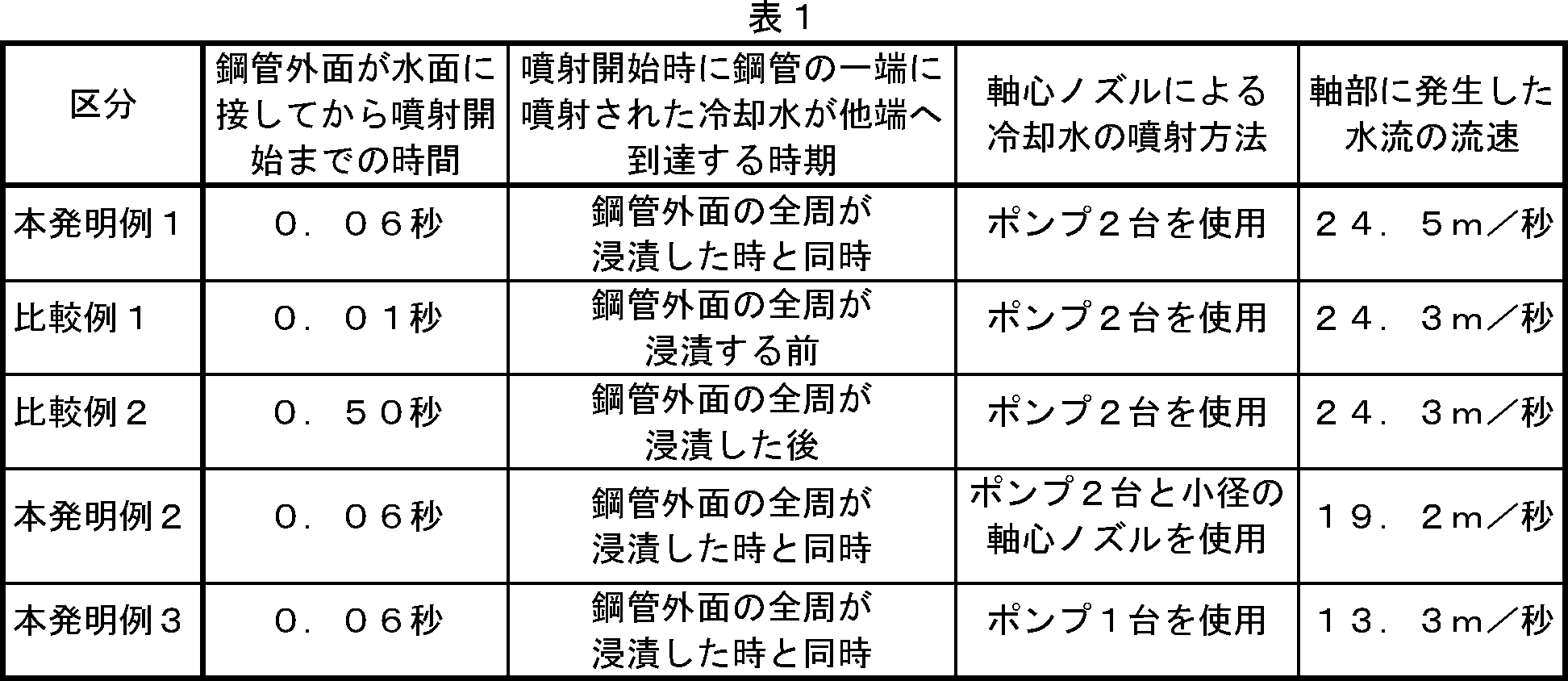
- the time from when the outer surface of the steel pipe comes into contact with the water surface to the start of the injection of the cooling water by the axial nozzle, the cooling water injection method by the axial nozzle and the shaft of the steel pipe Table 1 shows the flow velocity of the water flow generated in the section.
- evaluation index As an evaluation index, the tensile strength TS and the yield strength YS on the top end side and the bottom end side of the steel pipe were measured, and the strength difference in each longitudinal direction was calculated.
- a No. 12 tensile test piece specified in JIS Z 2201 is collected from the vicinity of the top end and bottom end of the steel pipe, and subjected to a tensile test according to the test method specified in JIS Z 2241. Tensile strength TS and yield strength YS are obtained. It was measured.
- FIG. 5 is a diagram showing the relationship between the timing of starting the cooling water injection from the axial nozzle and the strength difference between the top end side and the bottom end side of the quenched steel pipe.
- the timing of starting the cooling water injection from the axial nozzle is the time (seconds) from the time when the outer surface of the steel pipe immersed in the water tank contacts the water surface until the cooling water injection by the axial nozzle starts. Show.
- the injection start time by the axial nozzle is advanced, the time from when the outer surface of the steel pipe contacts the water surface until the injection by the axial nozzle is started is 0.01 seconds, and the yield strength YS The difference in strength is 26 MPa and the difference in tensile strength TS is 23 MPa.
- the injection start time by the axial nozzle is delayed, and the injection by the axial nozzle is started after the outer surface of the steel pipe is in contact with the water surface. Up to 0.50 seconds, the strength difference in yield strength YS was 31 MPa, and the strength difference in tensile strength TS was 31 MPa.
- Example 1 of the present invention the cooling water sprayed to the top end of the steel pipe when the injection is started reaches the bottom end when the entire circumference of the steel pipe outer surface is immersed.
- the time until the injection by the nozzle was started was 0.06 seconds
- the strength difference in yield strength YS was 18 MPa
- the strength difference in tensile strength TS was 8 MPa. From these, by the quenching method of the steel pipe of the present invention, the timing for starting the injection of the cooling water from the axial nozzle is adjusted, and the cooling water injected to the top end of the steel pipe when the injection is started It was confirmed that the strength difference in the longitudinal direction of the quenched steel pipe was reduced by reaching the bottom end when dipping.
- FIG. 6 is a diagram showing the relationship between the flow velocity of the water flow generated in the shaft portion of the steel pipe and the strength difference between the top end side and the bottom end side of the quenched steel pipe.
- Example 2 of the present invention the flow velocity of the water flow in the shaft portion is reduced to 29.2 m / second compared to 24.5 m / second in Example 1 of the present invention, and the strength difference in yield strength YS. was 24 MPa, and the difference in tensile strength TS was 22 MPa.
- Example 3 of the present invention the flow velocity of the water flow at the shaft portion was further reduced to 13.3 m / sec, the strength difference in yield strength YS was 75 MPa, and the strength difference in tensile strength TS was 34 MPa.
- the strength difference in the longitudinal direction of the quenched steel pipe increased when the flow velocity generated in the shaft part of the steel pipe during quenching decreased.
- the strength difference between the yield strength YS and the tensile strength TS of the heat-treated steel pipe is reduced to 20 MPa or less by setting the flow velocity generated in the shaft portion of the steel pipe to 23 m / second or more. did it.
- the steel pipe quenching method of the present invention has the following remarkable effects. (1) Cooling water sprayed to the top end of the steel pipe when injection is started reaches the bottom end when the entire circumference of the steel pipe outer surface is immersed, and is cooled from an opening provided in the water tank wall surface facing the axial nozzle. By discharging water, the cooling rate in the vicinity of the bottom end of the rapidly cooled steel pipe can be secured. (2) By moving the axial nozzle following the axis of the steel pipe, a water flow can be generated in the shaft part of the steel pipe from the stage where a part of the steel pipe is immersed in the water tank, and the cooling rate of the steel pipe can be improved. .
- the steel pipe manufacturing method of the present invention using such a steel pipe quenching method can reduce the strength difference occurring in the longitudinal direction and improve the quality in the obtained steel pipe, so that the steel pipe of high strength and high quality can be obtained. It is useful for the production of
Landscapes
- Chemical & Material Sciences (AREA)
- Engineering & Computer Science (AREA)
- Physics & Mathematics (AREA)
- Thermal Sciences (AREA)
- Crystallography & Structural Chemistry (AREA)
- Mechanical Engineering (AREA)
- Materials Engineering (AREA)
- Metallurgy (AREA)
- Organic Chemistry (AREA)
- Heat Treatment Of Articles (AREA)
Abstract
加熱された鋼管(2)を、その軸と水面を平行にした状態で水槽(3)に浸漬して専ら鋼管外面を冷却し、軸心ノズル(8)から冷却水を噴射して鋼管の一端から他端に向けた水流を鋼管の軸部に発生させ、専ら鋼管内面を冷却し、鋼管全面を急冷する鋼管の焼入れ方法において、軸心ノズル(8)を鋼管(2)の軸に追従して移動させ、鋼管(2)を水槽(3)に浸漬させつつ、軸心ノズル(8)から冷却水の噴射を開始するに際し、噴射を開始した時に鋼管の一端に噴射された冷却水が、鋼管外面の全周が浸漬する時に他端に到達するように噴射を開始することにより、焼入れが施された鋼管の長手方向に発生する強度差を低減することができる。この場合、水槽(3)の軸心ノズル(8)と対向する壁面に開口部(3a)を設け、当該開口部(3a)から冷却水を排出するのが好ましく、鋼管(2)の軸部に水流を発生させる際に、流速を23m/秒以上とするのが好ましい。
Description
本発明は、加熱された鋼管を水槽に浸漬して急冷する鋼管の焼入れ方法およびそれを用いた鋼管の製造方法に関し、さらに詳しくは焼入れが施された鋼管の長手方向に発生する強度差を低減することができる鋼管の製造方法に関する。
所望の強度を有する鋼管を製造するため、その製造過程で焼入れおよび焼戻しからなる熱処理が鋼管に施される。焼入れを鋼管に施す際には、冷却能力が大きいことから、加熱された鋼管を水槽に浸漬して急冷する焼入れ方法が多用される。
図1は、加熱された鋼管を水槽に浸漬する処理の一例を示す模式図である。同図に示す焼入れ装置1は、鋼管2を支持するクランプ装置5と、水槽3とから構成される。クランプ装置5は、第1アーム6と、揺動可能にして第1アームに取付けられた第2アーム7とからなる。第1アーム6は、鋼管を支持する駆動ローラ61およびローラ62を備え、第2アーム7は、鋼管を支持するローラ71を備える。
同図に示す焼入れ装置を用いて加熱された鋼管を水槽に浸漬する際には、同図の白抜き矢印で示す方向に第2アーム7を揺動させた後、加熱された鋼管を第1アーム6が備える駆動ローラ61およびローラ62上に載置する。その後、第2アームを揺動させて同図に示す位置に戻し、加熱された鋼管を第1アームが備える駆動ローラ61およびローラ62と、第2アームが備える2つのローラ71により回転可能に支持する。駆動ローラ61の回転に伴って鋼管2を回転させつつ(同図のクロスハッチングを施した矢印参照)、同図において想像線で示すようにクランプ装置5を揺動させ、鋼管を水槽に浸漬する(斜線を施した矢印参照)。
鋼管を回転させつつ水槽に浸漬するのは、浸漬された鋼管の水面側と水槽底面側で冷却速度が異なる場合があり、焼入れが施された鋼管で部分的に強度が低下するのを防止するためである。この際、水槽に浸漬された鋼管の冷却効果を高めるとともに、鋼管外面と鋼管内面を均一に冷却するため、一般的に、鋼管の軸部に水流を発生させる。
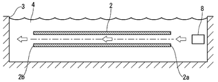
図2は、従来の鋼管の焼入れ方法であって、水槽に浸漬された鋼管の軸部に水流を発生させて鋼管を急冷する処理を示す模式図である。同図では、水槽3と、水槽に浸漬された鋼管2と、鋼管の軸上に配置された軸心ノズル8を示す。同図に示すように、軸心ノズル8から鋼管の一端2aの軸部に冷却水を噴射することにより、鋼管の一端2aから他端2bに向けた水流が鋼管の軸部に発生する(同図の白抜き矢印参照)。以下、焼入れの際に軸心ノズルの近くに配置された鋼管の一端2aをトップ端、他端2bをボトム端ともいう。
従来の鋼管の焼入れ方法では、鋼管の軸部に水流を発生させることにより、急冷する際に鋼管の外面に比べて内面が高温となり、焼入れが施された鋼管の外面側と内面側で強度差が発生するのを防止している。
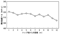
図3は、従来の鋼管の焼入れ方法により焼入れが施された鋼管における、トップ端からの距離と降伏強度の関係を示す図である。同図では、横軸に鋼管のトップ端からの距離(m)、縦軸に降伏強度YS(MPa)を示す。同図に示す降伏強度は、加熱された鋼管を急冷して焼入れを施した鋼管のものである。加熱された鋼管の急冷では、前記図1に示すクランプ装置を備えた焼入れ装置を用いて加熱された鋼管を回転可能に保持して水槽に浸漬し、前記図2に示す鋼管の軸上に配置された軸心ノズルにより鋼管の軸部に水流を発生させた。焼入れに用いた鋼管は、API規格のX65グレードに相当する強度を有する炭素鋼とし、外径を168.3mm、肉厚を18.52mm、長さを12mとした。
同図に示すように、従来の鋼管の焼入れ方法では、鋼管のトップ端側に比べてボトム端側の降伏強度が低下している。鋼管のトップ端側とボトム端側の強度差が大きくなると、製品品質が低下して問題となる。
加熱された鋼管を水槽に浸漬して急冷する焼入れ方法に関し、従来から種々の提案がなされており、例えば特許文献1および2がある。特許文献1は、加熱された鋼管を、その軸と水面を平行にして水槽に投入すると、軸部に発生する気泡により鋼管に浮力が作用してボトム端が水面まで浮上して冷却が不十分となり、焼入れが施された鋼管のトップ端側とボトム端側に生じる強度差を低減することを目的とする。特許文献1に記載の鋼管の焼入れ方法では、気泡によりボトム端が浮上するタイミングに合わせて、水槽に供給する水量を急速増加して高水位進行流を形成し、ボトム端周辺の水位を上昇させて鋼管のボトム端が水面まで浮上するのを防止するとしている。
また、特許文献2では、特許文献1に記載の鋼管の焼入れ方法において、高水位進行流により鋼管のボトム端と水槽の壁面が衝突して疵が発生する問題を解決することを目的とする。特許文献2に記載の鋼管の焼入れ方法では、水槽の断面積を鋼管のボトム端側で小さくすることにより、高水位進行流を形成するために必要な水量を低減し、鋼管が水流に流されてボトム端と水槽の壁面を衝突させることなく、ボトム端が水面まで浮上するのを防止できるとしている。
特許文献1および2に記載の加熱された鋼管を水槽に浸漬する焼入れ方法は、鋼管のボトム端が水面まで浮上することにより、焼入れが施された鋼管の長手方向に発生する強度差を低減することを目的としている。しかし、前記図1に示すクランプ装置を備えた焼入れ装置を用い、鋼管のボトム端側を水面まで浮上させることなく、鋼管に焼入れを施した場合でも、前記図3に示すように焼入れが施された鋼管のボトム端側とトップ端側で強度差が発生する。
前述の通り、従来の加熱された鋼管を水槽に浸漬する焼入れ方法では、焼入れが施された鋼管において、急冷される際に軸心ノズルから近いトップ端側と比べて他端のボトム端側の強度が低下する問題がある。本発明は、このような状況に鑑みてなされたものであり、鋼管の長手方向に発生する強度差を低減できる鋼管の焼入れ方法およびそれを用いた鋼管の製造方法を提供することを目的とする。
本発明者は、上記問題を解決するため、加熱された鋼管を水槽に浸漬して専ら鋼管外面を冷却し、軸心ノズルにより鋼管の軸部に水流を発生させて専ら鋼管内面を冷却し、鋼管全面を急冷する鋼管の焼入れ方法において、鋼管を水槽に浸漬させる際、軸心ノズルから冷却水の噴射を開始する時期について検討した。その結果、軸心ノズルとして鋼管の軸に追従して移動する給水ノズルを用い、噴射を開始した時に鋼管の一端に噴射された冷却水を、鋼管外面の全周が浸漬する時に他端に到達させることにより、急冷される鋼管のボトム端近傍で冷却速度を確保でき、焼入れが施された鋼管の長手方向に発生する強度差を低減できることを知見した。
また、前記図2に示す従来の焼入れ装置において、軸心ノズルと対向する水槽壁面に開口部を設け、当該開口部から冷却水を排出してボトム端周辺の水圧を低下させることにより、鋼管の軸部に発生する水流の流速を高め、焼入れが施された鋼管の長手方向に発生する強度差を低減できることを知見した。
さらに、鋼管の軸部に水流を発生させる際に、流速を23m/秒以上とすることにより、焼入れが施された鋼管の長手方向に発生する強度差を低減できることを知見した。
本発明は、上記の知見に基づいて完成したものであり、下記(1)~(3)の鋼管の焼入れ方法、および下記(4)の鋼管の製造方法を要旨としている:
(1)加熱された鋼管を、その軸と水面を平行にした状態で水槽に浸漬して専ら鋼管外面を冷却し、軸心ノズルから冷却水を噴射して鋼管の一端から他端に向けた水流を鋼管の軸部に発生させ、専ら鋼管内面を冷却し、鋼管全面を急冷する鋼管の焼入れ方法であって、前記軸心ノズルを鋼管の軸に追従して移動させ、鋼管を水槽に浸漬させつつ、軸心ノズルから冷却水の噴射を開始するに際し、噴射を開始した時に鋼管の一端に噴射された冷却水が、鋼管外面の全周が浸漬する時に他端に到達するように噴射を開始することを特徴とする鋼管の焼入れ方法。
(2)前記水槽の軸心ノズルと対向する壁面に開口部を設け、当該開口部から冷却水を排出することを特徴とする上記(1)に記載の鋼管の焼入れ方法。
(3)前記鋼管の軸部に水流を発生させる際に、流速を23m/秒以上とすることを特徴とする上記(1)または(2)に記載の鋼管の焼入れ方法。
(4)鋼管に焼き入れを施すにあたり、上記(1)~(3)のいずれかに記載の焼入れ方法により焼入れを施すことを特徴とする鋼管の製造方法。
本発明の鋼管の焼入れ方法は、下記の顕著な効果を有する。
(1)噴射を開始した時に鋼管のトップ端に噴射した冷却水を、鋼管外面の全周が浸漬する時にボトム端に到達させるとともに、軸心ノズルと対向する水槽壁面に設けた開口部から冷却水を排出することにより、急冷される鋼管のボトム端近傍における冷却速度を確保することができる。
(2)軸心ノズルを鋼管の軸に追従して移動させることにより、鋼管の一部が水槽に浸漬した段階から鋼管の軸部に水流を発生させ、鋼管の冷却速度を向上させることができる。
(1)噴射を開始した時に鋼管のトップ端に噴射した冷却水を、鋼管外面の全周が浸漬する時にボトム端に到達させるとともに、軸心ノズルと対向する水槽壁面に設けた開口部から冷却水を排出することにより、急冷される鋼管のボトム端近傍における冷却速度を確保することができる。
(2)軸心ノズルを鋼管の軸に追従して移動させることにより、鋼管の一部が水槽に浸漬した段階から鋼管の軸部に水流を発生させ、鋼管の冷却速度を向上させることができる。
このような鋼管の焼入れ方法を用いた本発明の鋼管の製造方法は、得られる鋼管において、長手方向に発生する強度差を低減でき、品質を高めることができる。
以下に、本発明の鋼管の焼入れ方法およびそれを用いた鋼管の製造方法について、図面に基づいて説明する。
図4は、本発明の鋼管の焼入れ方法による焼入れ処理例を説明する模式図であり、図4(a)は鋼管を水槽に浸漬する前の状態を、図4(b)は鋼管の外周の一部が水槽に浸漬した状態、図4(c)は鋼管の全周が水槽に浸漬した状態を、図4(d)は鋼管を水槽の中央に配置した状態をそれぞれ示す。図4(a)~(d)では、加熱された鋼管2と、当該鋼管を浸漬する水槽3と、鋼管の軸に追従して移動する軸心ノズル8とを示す。水槽3は、軸心ノズル8と対向する水槽壁面に開口部3aと、いずれにも図示しない給水ノズルとが設けられ、給水ノズルから冷却水が供給されるとともに、開口部から冷却水が排出されることにより、図4(a)~(d)の白抜き矢印の方向に水流を発生させる。
このような焼入れ装置を用いた本発明の鋼管の焼入れ方法による焼入れ処理では、図4(a)に示すように加熱された鋼管を、その軸と水面を平行にした状態とする。この際、軸心ノズル8からの冷却水の噴射は停止させておく。
次に鋼管を下降させて水槽に浸漬させつつ、図4(b)に示すように、軸心ノズル8により鋼管の一端(トップ端)への噴射を開始する(図4(b)の斜線を施した矢印参照)。
軸心ノズルによる噴射を開始した後、鋼管を引き続き下降させて図4(c)に示すように鋼管外面の全周が浸漬する時に、噴射を開始した時に鋼管の一端(トップ端)に噴射された冷却水を他端(ボトム端)に到達させる(図4(c)の斜線を施した矢印参照)。
鋼管外面の全周を浸漬させた後、鋼管を引き続き下降させて図4(d)に示すように水槽の中央に配置し、軸心ノズル8と給水ノズルから水槽に冷却水を供給するとともに、開口部3aから排水することにより、鋼管が常温以下となるまで冷却し、その後、鋼管を水槽から引き上げる。
本発明の鋼管の焼入れ方法は、加熱された鋼管を、その軸と水面を平行にした状態で水槽に浸漬して専ら鋼管外面を冷却し、軸心ノズルから冷却水を噴射して鋼管の一端から他端に向けた水流を鋼管の軸部に発生させ、専ら鋼管内面を冷却し、鋼管全面を急冷する鋼管の焼入れ方法であって、軸心ノズルを鋼管の軸に追従して移動させ、鋼管を水槽に浸漬させつつ、軸心ノズルから冷却水の噴射を開始するに際し、噴射を開始した時に鋼管の一端に噴射された冷却水が、鋼管外面の全周が浸漬する時に他端に到達するように噴射を開始することを特徴とする。
前記図4(a)~(d)を用いて説明した通り、鋼管を水槽に浸漬させつつ、軸心ノズルから冷却水の噴射を開始するに際し、噴射を開始した時に鋼管の一端に噴射された冷却水が、鋼管外面の全周が浸漬する時に他端に到達するように噴射を開始する。これにより、鋼管のボトム端近傍が同時に内面および外面から冷却されることから、ボトム端近傍における冷却速度を確保して強度低下を抑制し、焼入れが施された鋼管の長手方向に発生する強度差を低減できる。
軸心ノズルによる冷却水噴射の開始時期が早いと、鋼管の外面の一部が水槽に浸漬される前に、軸部の水流によりボトム端近傍の内面が冷却される。このため、ボトム端近傍は一時的に内面からの冷却水のみにより冷却されるので、ボトム端近傍における冷却速度が不足して強度低下が顕著となり、焼入れが施された鋼管の長手方向の強度差が増加する。
一方、軸心ノズルによる冷却水噴射の開始時期が遅いと、鋼管のボトム端近傍の外面の全周が水槽に浸漬された後に、軸部の水流によりボトム端近傍の内面が冷却される。このため、ボトム端近傍は一時的に内面からの冷却が不十分となり、ボトム端近傍における冷却速度が不足して強度低下が顕著となり、焼入れが施された鋼管の長手方向の強度差が増加する。
噴射を開始した時に鋼管の一端に噴射された冷却水が他端に到達する時期と、鋼管外面の全周が浸漬する時期を同期させる方法として、鋼管を水面に下降させる速度や、軸部の水量の流速、軸心ノズルによる噴射の開始時期を調整する方法が考えられる。鋼管の焼入れでは、鋼管を可能な限り急速に冷却することが強度を確保するために重要であるから、鋼管を水面に下降させる速度および軸部の流速は、設備仕様の上限で操業するのが好ましい。このため、本発明の焼入れ方法では、軸心ノズルにより冷却水の噴射を開始する時期を調整することにより、鋼管外面の全周が浸漬する時に、噴射を開始した時に鋼管の一端に噴射された冷却水を他端に到達させるのが好ましい。
軸心ノズルを鋼管の軸に追従して移動させることにより、鋼管の一部が水槽に浸漬した段階から鋼管の軸部に水流を発生させ、水槽に浸漬する鋼管の冷却速度を向上させることができる。軸心ノズルを鋼管の軸に追従して移動させる方法として、例えば前記図1に示すクランプ装置5の第1アーム6に治具を用いて軸心ノズルを固定する方法を採用できる。これにより、軸心ノズルを鋼管の軸に追従して移動させるとともに、水泡によりボトム端側が水面まで浮上することなく鋼管を急冷できる。さらに、クランプ装置により鋼管を回転させながら浸漬することにより、急冷する際に鋼管の水面側と水槽底面側で冷却速度が異なり、焼入れが施された鋼管で部分的に強度が低下するのを防止できる。
本発明の鋼管の焼入れ方法では、水槽の軸心ノズルと対向する壁面に開口部を設け、当該開口部から冷却水を排出するのが好ましい。軸心ノズルと対向する水槽壁面に設けた開口部から冷却水を排出することにより、開口部周辺、すなわちボトム端側の水圧が低下する。このため、トップ端とボトム端の水圧差が大きくなり、軸部に発生する水流の流速を上昇させることができる。また、鋼管の冷却に用いられて温度が上昇し、ボトム端周辺に滞留する冷却水を、開口部から効率よく排出することができる。これらにより、鋼管を急冷する際にボトム端側の冷却速度を向上させることができ、その結果、焼入れが施された鋼管の長手方向に発生する強度差を低減することができる。
本発明の鋼管の焼入れ方法では、鋼管の軸部に発生させる水流の流速は、後述する実施例の図6で説明する通り、流速を23m/秒以上とするのが好ましい。同図に示す通り、軸部に発生させる水流の流速が増加すると、焼入れが施された鋼管の長手方向の強度差が減少し、流速を23m/秒以上とすることにより、強度差を20MPa以下に低減できるからである。
このように本発明の鋼管の焼入れ方法では、軸心ノズルから冷却水の噴射を開始する時期を規定するとともに、軸心ノズルと対向する水槽壁面に設けた開口部から冷却水を排出することにより、急冷される鋼管のボトム端近傍における冷却速度を確保することができる。この焼入れ方法を用いる本発明の鋼管の製造方法により、得られる鋼管のボトム端側の強度低下を抑制して長手方向に発生する強度差を低減でき、品質を高めることができる。
鋼管に焼入れを施す試験を行い、本発明の鋼管の焼入れ方法およびそれを用いた鋼管の製造方法による効果を検証した。
[試験方法]
本試験では、前記図4(a)~(d)を用いて説明した手順により鋼管を水槽に浸漬して急冷することにより焼入れを施した。この際、加熱された鋼管を前記図1に示す焼入れ装置に鋼管の軸に追従して移動する軸心ノズルを付加したものにより回転可能に支持した。焼入れを施す鋼管の材質は、焼入れ条件の違いを顕在化させるため、焼入れ性の低い材質とした。
本試験での試験条件は下記の通りとした。
鋼管:外径114.3mm、肉厚12.5mm、長さ12000mm、材質 API規格の5L2-X65Qグレードに相当する強度を有する炭素鋼
本試験では、前記図4(a)~(d)を用いて説明した手順により鋼管を水槽に浸漬して急冷することにより焼入れを施した。この際、加熱された鋼管を前記図1に示す焼入れ装置に鋼管の軸に追従して移動する軸心ノズルを付加したものにより回転可能に支持した。焼入れを施す鋼管の材質は、焼入れ条件の違いを顕在化させるため、焼入れ性の低い材質とした。
本試験での試験条件は下記の通りとした。
鋼管:外径114.3mm、肉厚12.5mm、長さ12000mm、材質 API規格の5L2-X65Qグレードに相当する強度を有する炭素鋼
本発明例1では、軸心ノズルから冷却水の噴射を開始する時期を調整し、噴射を開始した時に鋼管の一端(トップ端)に噴射された冷却水を、鋼管外面の全周が浸漬する時に他端(ボトム端)に到達させた。また、本発明例1では、2台のポンプを用いて軸心ノズルへ冷却水を供給し、鋼管のトップ端の軸部に冷却水を噴射した。
比較例1では、本発明例1に比べて軸心ノズルから冷却水の噴射を開始する時期を早くし、噴射を開始した時にトップ端に噴射した冷却水を、鋼管外面の全周が浸漬する前にボトム端に到達させた。比較例2では、本発明例1に比べて軸心ノズルから冷却水の噴射を開始する時期を遅くし、噴射を開始した時にトップ端に噴射した冷却水を、鋼管外面の全周が浸漬した後にボトム端に到達させた。
本発明例2では、本発明例1に比べて軸心ノズルの径を小さくし、軸部に発生させる水流の流速を低下させた。本発明例3では、軸心ノズルに冷却水に供給するポンプを1台とし、本発明例1および2に比べて軸部に発生させる水流の流速を低下させた。本発明例1~3並びに比較例1および2における、鋼管外面が水面に接してから軸心ノズルによる冷却水の噴射を開始するまでの時間、軸心ノズルによる冷却水の噴射方法および鋼管の軸部に発生した水流の流速を表1に示す。
[評価指標]
評価指標として鋼管のトップ端側とボトム端側の引張強度TSおよび降伏強度YSを測定し、それぞれの長手方向の強度差を算出した。鋼管のトップ端およびボトム端の近傍からJIS Z 2201に規定される12号引張試験片を採取し、JIS Z 2241に規定される試験方法に準じて引張試験行い、引張強度TSおよび降伏強度YSを測定した。
評価指標として鋼管のトップ端側とボトム端側の引張強度TSおよび降伏強度YSを測定し、それぞれの長手方向の強度差を算出した。鋼管のトップ端およびボトム端の近傍からJIS Z 2201に規定される12号引張試験片を採取し、JIS Z 2241に規定される試験方法に準じて引張試験行い、引張強度TSおよび降伏強度YSを測定した。
[試験結果]
図5は、軸心ノズルから冷却水の噴射を開始する時期と、焼入れが施された鋼管のトップ端側とボトム端側の強度差の関係を示す図である。同図では、軸心ノズルから冷却水の噴射を開始する時期を、水槽に浸漬される鋼管の外面が水面に接してから軸心ノズルによる冷却水の噴射を開始するまでの時間(秒)で示す。
図5は、軸心ノズルから冷却水の噴射を開始する時期と、焼入れが施された鋼管のトップ端側とボトム端側の強度差の関係を示す図である。同図では、軸心ノズルから冷却水の噴射を開始する時期を、水槽に浸漬される鋼管の外面が水面に接してから軸心ノズルによる冷却水の噴射を開始するまでの時間(秒)で示す。
同図に示すように、比較例1では、軸心ノズルによる噴射の開始時期を早め、鋼管外面が水面に接してから軸心ノズルによる噴射を開始するまでを0.01秒とし、降伏強度YSの強度差は26MPa、引張強度TSの強度差は23MPaであり、比較例2では、軸心ノズルによる噴射の開始時期を遅め、鋼管外面が水面に接してから軸心ノズルによる噴射を開始するまでを0.50秒とし、降伏強度YSの強度差は31MPa、引張強度TSの強度差は31MPaであった。
一方、本発明例1では、噴射を開始した時に鋼管のトップ端に噴射した冷却水を、鋼管外面の全周が浸漬する時にボトム端に到達させるため、鋼管外面が水面に接してから軸心ノズルによる噴射を開始するまでを0.06秒とし、降伏強度YSの強度差は18MPa、引張強度TSの強度差は8MPaであった。これらから、本発明の鋼管の焼入れ方法により、軸心ノズルから冷却水の噴射を開始する時期を調整し、噴射を開始した時に鋼管のトップ端に噴射した冷却水を、鋼管外面の全周が浸漬する時にボトム端に到達させることにより、焼入れが施された鋼管の長手方向の強度差が低減することが確認できた。
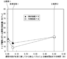
図6は、鋼管の軸部に発生させた水流の流速と、焼入れが施された鋼管のトップ端側とボトム端側の強度差の関係を示す図である。同図に示すように、本発明例2では、軸部の水流の流速を本発明例1での24.5m/秒に比べて低下させて19.2m/秒とし、降伏強度YSの強度差は24MPa、引張強度TSの強度差は22MPaであった。また、本発明例3では、軸部の水流の流速をさらに低下させて13.3m/秒とし、降伏強度YSの強度差は75MPa、引張強度TSの強度差は34MPaであった。
したがって、急冷する際に鋼管の軸部に発生させる流速が低下すると、焼入れが施された鋼管の長手方向の強度差が増加することが確認できた。また、同図から鋼管の軸部に発生させる流速を23m/秒以上とすることにより、熱処理が施された鋼管の降伏強度YSおよび引張強度TSの強度差が20MPa以下に低減されることが確認できた。
本発明の鋼管の焼入れ方法は、下記の顕著な効果を有する。
(1)噴射を開始した時に鋼管のトップ端に噴射した冷却水を、鋼管外面の全周が浸漬する時にボトム端に到達させるとともに、軸心ノズルと対向する水槽壁面に設けた開口部から冷却水を排出することにより、急冷される鋼管のボトム端近傍における冷却速度を確保することができる。
(2)軸心ノズルを鋼管の軸に追従して移動させることにより、鋼管の一部が水槽に浸漬した段階から鋼管の軸部に水流を発生させ、鋼管の冷却速度を向上させることができる。
(1)噴射を開始した時に鋼管のトップ端に噴射した冷却水を、鋼管外面の全周が浸漬する時にボトム端に到達させるとともに、軸心ノズルと対向する水槽壁面に設けた開口部から冷却水を排出することにより、急冷される鋼管のボトム端近傍における冷却速度を確保することができる。
(2)軸心ノズルを鋼管の軸に追従して移動させることにより、鋼管の一部が水槽に浸漬した段階から鋼管の軸部に水流を発生させ、鋼管の冷却速度を向上させることができる。
このような鋼管の焼入れ方法を用いた本発明の鋼管の製造方法は、得られる鋼管において、長手方向に発生する強度差を低減でき、品質を高めることができるので、高強度かつ高品質な鋼管の製造に有用である。
1:焼入れ装置、 2:鋼管、 2a:トップ端、 2b:ボトム端、
3:水槽、 3a:開口部、 4:冷却水、 5:クランプ装置、
6:第1アーム、 61:駆動ローラ、 62:ローラ、
7:第2アーム、 71:ローラ、 8:軸心ノズル
3:水槽、 3a:開口部、 4:冷却水、 5:クランプ装置、
6:第1アーム、 61:駆動ローラ、 62:ローラ、
7:第2アーム、 71:ローラ、 8:軸心ノズル
Claims (4)
- 加熱された鋼管を、その軸と水面を平行にした状態で水槽に浸漬して専ら鋼管外面を冷却し、軸心ノズルから冷却水を噴射して鋼管の一端から他端に向けた水流を鋼管の軸部に発生させ、専ら鋼管内面を冷却し、鋼管全面を急冷する鋼管の焼入れ方法であって、
前記軸心ノズルを鋼管の軸に追従して移動させ、
鋼管を水槽に浸漬させつつ、軸心ノズルから冷却水の噴射を開始するに際し、噴射を開始した時に鋼管の一端に噴射された冷却水が、鋼管外面の全周が浸漬する時に他端に到達するように噴射を開始することを特徴とする鋼管の焼入れ方法。 - 前記水槽の軸心ノズルと対向する壁面に開口部を設け、当該開口部から冷却水を排出することを特徴とする請求項1に記載の鋼管の焼入れ方法。
- 前記鋼管の軸部に水流を発生させる際に、流速を23m/秒以上とすることを特徴とする請求項1または2に記載の鋼管の焼入れ方法。
- 鋼管に焼き入れを施すにあたり、請求項1~3のいずれかに記載の焼入れ方法により焼入れを施すことを特徴とする鋼管の製造方法。
Priority Applications (3)
| Application Number | Priority Date | Filing Date | Title |
|---|---|---|---|
| EP11821291.9A EP2612932B1 (en) | 2010-09-02 | 2011-08-26 | Steel pipe quenching method and steel pipe manufacturing method using same |
| CN201180042312.3A CN103080345B (zh) | 2010-09-02 | 2011-08-26 | 钢管的淬火方法及使用该淬火方法的钢管的制造方法 |
| US13/819,842 US9267186B2 (en) | 2010-09-02 | 2011-08-26 | Method for quenching steel pipe and method for producing steel pipe using the same |
Applications Claiming Priority (2)
| Application Number | Priority Date | Filing Date | Title |
|---|---|---|---|
| JP2010196549A JP5071537B2 (ja) | 2010-09-02 | 2010-09-02 | 鋼管の焼入れ方法およびそれを用いた鋼管の製造方法 |
| JP2010-196549 | 2010-09-02 |
Publications (1)
| Publication Number | Publication Date |
|---|---|
| WO2012029268A1 true WO2012029268A1 (ja) | 2012-03-08 |
Family
ID=45772394
Family Applications (1)
| Application Number | Title | Priority Date | Filing Date |
|---|---|---|---|
| PCT/JP2011/004758 Ceased WO2012029268A1 (ja) | 2010-09-02 | 2011-08-26 | 鋼管の焼入れ方法およびそれを用いた鋼管の製造方法 |
Country Status (5)
| Country | Link |
|---|---|
| US (1) | US9267186B2 (ja) |
| EP (1) | EP2612932B1 (ja) |
| JP (1) | JP5071537B2 (ja) |
| CN (1) | CN103080345B (ja) |
| WO (1) | WO2012029268A1 (ja) |
Cited By (1)
| Publication number | Priority date | Publication date | Assignee | Title |
|---|---|---|---|---|
| US20150247227A1 (en) * | 2012-10-04 | 2015-09-03 | Jfe Steel Corporation | Method for manufacturing heavy wall steel pipe |
Families Citing this family (8)
| Publication number | Priority date | Publication date | Assignee | Title |
|---|---|---|---|---|
| CN102965480B (zh) * | 2012-11-16 | 2014-03-05 | 上海交通大学 | 一种厚壁钢管淬火冷却方法及设备 |
| CN107250393B (zh) | 2015-02-06 | 2020-04-03 | 杰富意钢铁株式会社 | 钢管的淬火方法、钢管的淬火装置、钢管的制造方法及钢管的制造设备 |
| JP6784476B2 (ja) * | 2015-03-24 | 2020-11-11 | 日本発條株式会社 | 中空スタビライザの製造方法 |
| JP6494357B2 (ja) * | 2015-03-24 | 2019-04-03 | 日本発條株式会社 | 中空スタビライザの製造方法 |
| GB2548416B (en) * | 2016-03-15 | 2019-06-12 | Arconic Inc | Improved methods for quenching metal tubes |
| IT201700025493A1 (it) * | 2017-03-08 | 2018-09-08 | Gf Elti S R L | Procedimento e apparecchiatura per il raffreddamento di tubi in metallo nell'esecuzione di trattamenti termici, in particolare per la tempra di tubi in acciaio. |
| CN115341086A (zh) * | 2022-08-10 | 2022-11-15 | 中国重型机械研究院股份公司 | 一种用于超大规格钢管整体淬火工艺的设备和方法 |
| CN116497191B (zh) * | 2023-06-19 | 2023-11-14 | 太仓市惠得利弹簧有限公司 | 一种弹簧加工淬火装置 |
Citations (6)
| Publication number | Priority date | Publication date | Assignee | Title |
|---|---|---|---|---|
| JPS55125233A (en) * | 1979-03-22 | 1980-09-26 | Kawasaki Steel Corp | Immersion hardening method of steel pipe |
| JPS5822326A (ja) * | 1981-07-31 | 1983-02-09 | Nippon Kokan Kk <Nkk> | 多連式焼入れ装置 |
| JPS5935627A (ja) * | 1982-08-19 | 1984-02-27 | Kawasaki Steel Corp | 鋼管浸漬焼入装置における管内面冷却水噴射時期決め装置 |
| JPS5974228A (ja) * | 1982-10-21 | 1984-04-26 | Kawasaki Steel Corp | 鋼管の浸漬焼入装置 |
| JPH0790378A (ja) | 1993-09-24 | 1995-04-04 | Kawasaki Steel Corp | 鋼管の焼入方法 |
| JPH0841544A (ja) | 1994-07-28 | 1996-02-13 | Kawasaki Steel Corp | 鋼管の焼入方法 |
Family Cites Families (9)
| Publication number | Priority date | Publication date | Assignee | Title |
|---|---|---|---|---|
| US3877685A (en) * | 1973-07-16 | 1975-04-15 | Algoma Steel Corp Ltd | Steel hardening apparatus |
| US4376528A (en) * | 1980-11-14 | 1983-03-15 | Kawasaki Steel Corporation | Steel pipe hardening apparatus |
| JPS5816028A (ja) * | 1981-07-20 | 1983-01-29 | Nippon Kokan Kk <Nkk> | 多連式焼入れ装置 |
| JPS6173830A (ja) * | 1984-09-18 | 1986-04-16 | Kawasaki Steel Corp | 均一強度を有する直接焼入鋼管の製造方法 |
| JPS61127820A (ja) * | 1984-11-26 | 1986-06-16 | Kawasaki Steel Corp | 調質鋼管の製造方法 |
| JPS63186831A (ja) * | 1987-01-28 | 1988-08-02 | Nippon Steel Corp | 鋼管の内面焼入方法 |
| CN2866519Y (zh) * | 2005-11-29 | 2007-02-07 | 宝山钢铁股份有限公司 | 一种钢管水淬热处理装置 |
| JP2007321178A (ja) * | 2006-05-30 | 2007-12-13 | Sumitomo Metal Ind Ltd | 鋼管の冷却方法 |
| CN201276583Y (zh) * | 2008-09-29 | 2009-07-22 | 衡阳华菱连轧管有限公司 | 一种对钢管采用外淋内喷加浸浴式淬火的装置 |
-
2010
- 2010-09-02 JP JP2010196549A patent/JP5071537B2/ja active Active
-
2011
- 2011-08-26 EP EP11821291.9A patent/EP2612932B1/en active Active
- 2011-08-26 US US13/819,842 patent/US9267186B2/en active Active
- 2011-08-26 WO PCT/JP2011/004758 patent/WO2012029268A1/ja not_active Ceased
- 2011-08-26 CN CN201180042312.3A patent/CN103080345B/zh active Active
Patent Citations (6)
| Publication number | Priority date | Publication date | Assignee | Title |
|---|---|---|---|---|
| JPS55125233A (en) * | 1979-03-22 | 1980-09-26 | Kawasaki Steel Corp | Immersion hardening method of steel pipe |
| JPS5822326A (ja) * | 1981-07-31 | 1983-02-09 | Nippon Kokan Kk <Nkk> | 多連式焼入れ装置 |
| JPS5935627A (ja) * | 1982-08-19 | 1984-02-27 | Kawasaki Steel Corp | 鋼管浸漬焼入装置における管内面冷却水噴射時期決め装置 |
| JPS5974228A (ja) * | 1982-10-21 | 1984-04-26 | Kawasaki Steel Corp | 鋼管の浸漬焼入装置 |
| JPH0790378A (ja) | 1993-09-24 | 1995-04-04 | Kawasaki Steel Corp | 鋼管の焼入方法 |
| JPH0841544A (ja) | 1994-07-28 | 1996-02-13 | Kawasaki Steel Corp | 鋼管の焼入方法 |
Cited By (2)
| Publication number | Priority date | Publication date | Assignee | Title |
|---|---|---|---|---|
| US20150247227A1 (en) * | 2012-10-04 | 2015-09-03 | Jfe Steel Corporation | Method for manufacturing heavy wall steel pipe |
| US9506132B2 (en) * | 2012-10-04 | 2016-11-29 | Jfe Steel Corporation | Method for manufacturing heavy wall steel pipe |
Also Published As
| Publication number | Publication date |
|---|---|
| JP2012052197A (ja) | 2012-03-15 |
| US20130160903A1 (en) | 2013-06-27 |
| JP5071537B2 (ja) | 2012-11-14 |
| EP2612932A1 (en) | 2013-07-10 |
| US9267186B2 (en) | 2016-02-23 |
| CN103080345A (zh) | 2013-05-01 |
| EP2612932B1 (en) | 2018-01-03 |
| CN103080345B (zh) | 2014-06-18 |
| EP2612932A4 (en) | 2017-08-09 |
Similar Documents
| Publication | Publication Date | Title |
|---|---|---|
| JP5071537B2 (ja) | 鋼管の焼入れ方法およびそれを用いた鋼管の製造方法 | |
| CN102925633B (zh) | 一种钢板淬火冷却方法及设备 | |
| CN1064276C (zh) | 无缝钢管的制造方法及其制造设备 | |
| WO2015043058A1 (zh) | 一种非调质钢的生产工艺 | |
| CN1299855C (zh) | 生产超低碳钢板的方法 | |
| WO2007139158A1 (ja) | 鋼管の冷却方法 | |
| CN1861813A (zh) | 通过感应加热对长棒进行连续热处理的方法及装置 | |
| CN101379203B (zh) | 感应淬火方法 | |
| EP3632577B1 (en) | Plastic spraying process and apparatus for bearing retainer | |
| US7739980B2 (en) | Apparatus for manufacturing steel tube and method for manufacturing the same | |
| CN110177890A (zh) | 无铅索氏体化工艺和设备 | |
| CN116833242B (zh) | 一种均温板散热器铜带生产工艺 | |
| JPS63186831A (ja) | 鋼管の内面焼入方法 | |
| KR20150107588A (ko) | 주조봉/주조관 제조 장치 및 그 장치에 의해 얻어지는 금속 재료 | |
| JP6007952B2 (ja) | 鋼材の冷却方法、鋼材の冷却設備、鋼材の製造方法および鋼材の製造設備 | |
| JP3986864B2 (ja) | 焼入れ方法及び焼入れ装置 | |
| RU2299251C1 (ru) | Способ термической обработки труб | |
| CN115805414A (zh) | 一种改善车轮轮辋性能的毛坯车轮及其生产方法 | |
| KR101946352B1 (ko) | 선박엔진 피스톤크라운의 수중 고주파 열처리장치 | |
| CN107974545B (zh) | 钢管内滞留冷却水清除装置和方法 | |
| JP2021193206A (ja) | 金属管搬送装置およびめっき金属管の製造方法 | |
| JPS62202019A (ja) | 金属材料の焼入れ方法および装置 | |
| JPH0790378A (ja) | 鋼管の焼入方法 | |
| CN207031504U (zh) | 一种大容积缠绕气瓶钢质内胆及高压无缝气瓶热处理工装 | |
| JP2001089809A (ja) | 高周波焼入れ方法及びその装置 |
Legal Events
| Date | Code | Title | Description |
|---|---|---|---|
| WWE | Wipo information: entry into national phase |
Ref document number: 201180042312.3 Country of ref document: CN |
|
| 121 | Ep: the epo has been informed by wipo that ep was designated in this application |
Ref document number: 11821291 Country of ref document: EP Kind code of ref document: A1 |
|
| WWE | Wipo information: entry into national phase |
Ref document number: 13819842 Country of ref document: US |
|
| NENP | Non-entry into the national phase |
Ref country code: DE |
|
| WWE | Wipo information: entry into national phase |
Ref document number: 2011821291 Country of ref document: EP |