WO2012033003A1 - 燃料電池システム及びその運転方法 - Google Patents
燃料電池システム及びその運転方法 Download PDFInfo
- Publication number
- WO2012033003A1 WO2012033003A1 PCT/JP2011/069912 JP2011069912W WO2012033003A1 WO 2012033003 A1 WO2012033003 A1 WO 2012033003A1 JP 2011069912 W JP2011069912 W JP 2011069912W WO 2012033003 A1 WO2012033003 A1 WO 2012033003A1
- Authority
- WO
- WIPO (PCT)
- Prior art keywords
- fuel cell
- pulsation
- cell stack
- anode
- buffer tank
- Prior art date
- Legal status (The legal status is an assumption and is not a legal conclusion. Google has not performed a legal analysis and makes no representation as to the accuracy of the status listed.)
- Ceased
Links
Images






Classifications
-
- H—ELECTRICITY
- H01—ELECTRIC ELEMENTS
- H01M—PROCESSES OR MEANS, e.g. BATTERIES, FOR THE DIRECT CONVERSION OF CHEMICAL ENERGY INTO ELECTRICAL ENERGY
- H01M8/00—Fuel cells; Manufacture thereof
- H01M8/04—Auxiliary arrangements, e.g. for control of pressure or for circulation of fluids
- H01M8/04082—Arrangements for control of reactant parameters, e.g. pressure or concentration
- H01M8/04089—Arrangements for control of reactant parameters, e.g. pressure or concentration of gaseous reactants
-
- H—ELECTRICITY
- H01—ELECTRIC ELEMENTS
- H01M—PROCESSES OR MEANS, e.g. BATTERIES, FOR THE DIRECT CONVERSION OF CHEMICAL ENERGY INTO ELECTRICAL ENERGY
- H01M8/00—Fuel cells; Manufacture thereof
- H01M8/02—Details
- H01M8/0202—Collectors; Separators, e.g. bipolar separators; Interconnectors
- H01M8/0258—Collectors; Separators, e.g. bipolar separators; Interconnectors characterised by the configuration of channels, e.g. by the flow field of the reactant or coolant
-
- H—ELECTRICITY
- H01—ELECTRIC ELEMENTS
- H01M—PROCESSES OR MEANS, e.g. BATTERIES, FOR THE DIRECT CONVERSION OF CHEMICAL ENERGY INTO ELECTRICAL ENERGY
- H01M8/00—Fuel cells; Manufacture thereof
- H01M8/04—Auxiliary arrangements, e.g. for control of pressure or for circulation of fluids
- H01M8/04223—Auxiliary arrangements, e.g. for control of pressure or for circulation of fluids during start-up or shut-down; Depolarisation or activation, e.g. purging; Means for short-circuiting defective fuel cells
-
- H—ELECTRICITY
- H01—ELECTRIC ELEMENTS
- H01M—PROCESSES OR MEANS, e.g. BATTERIES, FOR THE DIRECT CONVERSION OF CHEMICAL ENERGY INTO ELECTRICAL ENERGY
- H01M8/00—Fuel cells; Manufacture thereof
- H01M8/04—Auxiliary arrangements, e.g. for control of pressure or for circulation of fluids
- H01M8/04223—Auxiliary arrangements, e.g. for control of pressure or for circulation of fluids during start-up or shut-down; Depolarisation or activation, e.g. purging; Means for short-circuiting defective fuel cells
- H01M8/04225—Auxiliary arrangements, e.g. for control of pressure or for circulation of fluids during start-up or shut-down; Depolarisation or activation, e.g. purging; Means for short-circuiting defective fuel cells during start-up
-
- H—ELECTRICITY
- H01—ELECTRIC ELEMENTS
- H01M—PROCESSES OR MEANS, e.g. BATTERIES, FOR THE DIRECT CONVERSION OF CHEMICAL ENERGY INTO ELECTRICAL ENERGY
- H01M8/00—Fuel cells; Manufacture thereof
- H01M8/04—Auxiliary arrangements, e.g. for control of pressure or for circulation of fluids
- H01M8/04298—Processes for controlling fuel cells or fuel cell systems
- H01M8/04313—Processes for controlling fuel cells or fuel cell systems characterised by the detection or assessment of variables; characterised by the detection or assessment of failure or abnormal function
- H01M8/0444—Concentration; Density
- H01M8/04462—Concentration; Density of anode exhausts
-
- H—ELECTRICITY
- H01—ELECTRIC ELEMENTS
- H01M—PROCESSES OR MEANS, e.g. BATTERIES, FOR THE DIRECT CONVERSION OF CHEMICAL ENERGY INTO ELECTRICAL ENERGY
- H01M8/00—Fuel cells; Manufacture thereof
- H01M8/04—Auxiliary arrangements, e.g. for control of pressure or for circulation of fluids
- H01M8/04298—Processes for controlling fuel cells or fuel cell systems
- H01M8/04694—Processes for controlling fuel cells or fuel cell systems characterised by variables to be controlled
- H01M8/04746—Pressure; Flow
- H01M8/04753—Pressure; Flow of fuel cell reactants
-
- H—ELECTRICITY
- H01—ELECTRIC ELEMENTS
- H01M—PROCESSES OR MEANS, e.g. BATTERIES, FOR THE DIRECT CONVERSION OF CHEMICAL ENERGY INTO ELECTRICAL ENERGY
- H01M8/00—Fuel cells; Manufacture thereof
- H01M8/24—Grouping of fuel cells, e.g. stacking of fuel cells
- H01M8/241—Grouping of fuel cells, e.g. stacking of fuel cells with solid or matrix-supported electrolytes
- H01M8/242—Grouping of fuel cells, e.g. stacking of fuel cells with solid or matrix-supported electrolytes comprising framed electrodes or intermediary frame-like gaskets
-
- H—ELECTRICITY
- H01—ELECTRIC ELEMENTS
- H01M—PROCESSES OR MEANS, e.g. BATTERIES, FOR THE DIRECT CONVERSION OF CHEMICAL ENERGY INTO ELECTRICAL ENERGY
- H01M8/00—Fuel cells; Manufacture thereof
- H01M8/24—Grouping of fuel cells, e.g. stacking of fuel cells
- H01M8/2465—Details of groupings of fuel cells
- H01M8/2483—Details of groupings of fuel cells characterised by internal manifolds
-
- H—ELECTRICITY
- H01—ELECTRIC ELEMENTS
- H01M—PROCESSES OR MEANS, e.g. BATTERIES, FOR THE DIRECT CONVERSION OF CHEMICAL ENERGY INTO ELECTRICAL ENERGY
- H01M8/00—Fuel cells; Manufacture thereof
- H01M8/04—Auxiliary arrangements, e.g. for control of pressure or for circulation of fluids
- H01M8/04223—Auxiliary arrangements, e.g. for control of pressure or for circulation of fluids during start-up or shut-down; Depolarisation or activation, e.g. purging; Means for short-circuiting defective fuel cells
- H01M8/04231—Purging of the reactants
-
- Y—GENERAL TAGGING OF NEW TECHNOLOGICAL DEVELOPMENTS; GENERAL TAGGING OF CROSS-SECTIONAL TECHNOLOGIES SPANNING OVER SEVERAL SECTIONS OF THE IPC; TECHNICAL SUBJECTS COVERED BY FORMER USPC CROSS-REFERENCE ART COLLECTIONS [XRACs] AND DIGESTS
- Y02—TECHNOLOGIES OR APPLICATIONS FOR MITIGATION OR ADAPTATION AGAINST CLIMATE CHANGE
- Y02E—REDUCTION OF GREENHOUSE GAS [GHG] EMISSIONS, RELATED TO ENERGY GENERATION, TRANSMISSION OR DISTRIBUTION
- Y02E60/00—Enabling technologies; Technologies with a potential or indirect contribution to GHG emissions mitigation
- Y02E60/30—Hydrogen technology
- Y02E60/50—Fuel cells
Definitions
- the present invention relates to an anode gas non-circulating fuel cell system and an operation method thereof.
- the conventional anode gas non-circulating fuel cell system disclosed in Patent Document 1 below includes a fuel cell stack [fuel cell stack] configured by stacking a plurality of fuel cells [fuel cells].
- a fuel cell stack [fuel cell stack] configured by stacking a plurality of fuel cells [fuel cells].
- a hydrogen tank As an anode gas supply system to the battery stack, a hydrogen tank, a supply cutoff valve and a pressure regulating valve are provided.
- a storage tank (buffer tank) and a discharge shut-off valve (purge valve) are provided as an anode exhaust gas discharge system from the fuel cell stack.
- the first control state in which the anode gas supply amount to the fuel cell stack is small and the second control state in which the supply amount is large are set, and the first and second control states are repeated to make the anode
- the gas supply pressure is pulsated.
- accumulation of impurities in some fuel cells is suppressed, and the anode exhaust gas is discharged to the storage tank.
- anode gas non-circulating fuel cell system a large amount of impurity gas (mainly nitrogen gas) tends to remain in the fuel cell stack when the system is stopped for a long time.
- impurity gas mainly nitrogen gas
- the residual impurity gas is discharged to the buffer tank as the inside of the fuel cell stack is replaced with hydrogen gas.
- the residual impurity gas (nitrogen gas) concentration in the tank is increased.
- An object of the present invention is to provide a method of operating a fuel cell system that can remove impurity gas while ensuring the hydrogen gas concentration in the fuel cell stack when the anode gas non-circulating fuel cell system is started.
- a first feature of the present invention is an anode gas non-circulating fuel cell system, in which a fuel cell stack configured by stacking a plurality of fuel cells and an anode off-gas discharged from the fuel cell stack.
- a buffer tank for discharging the contained impurity gas to the outside, an impurity gas concentration detector for detecting the impurity gas concentration inside the buffer tank, an anode gas supplier for supplying an anode gas to the fuel cell stack, And the impurity gas in the buffer tank detected by the impurity gas concentration detector when the impurity gas in the fuel cell stack is pumped to the buffer tank while pulsating the supply pressure by the anode gas supplier.
- at least one of the pulsation pressure and the pulsation cycle during anode gas supply is Nodogasu activation controlled by changing the supply takes place, to provide a fuel cell system, characterized in that.
- a second feature of the present invention is a fuel cell stack configured by stacking a plurality of fuel cells, and a buffer tank for discharging impurity gas contained in the anode off-gas discharged from the fuel cell stack to the outside And a method for operating an anode gas non-circulating fuel cell system having a structure in which the impurity gas in the fuel cell stack is pumped to the buffer tank by pulsating the supply pressure of the anode gas to the fuel cell stack
- the fuel cell system further includes an impurity gas concentration detector for detecting an impurity gas concentration inside the buffer tank, and the impurity gas in the buffer tank detected by the impurity gas concentration detector.
- the pulsation pressure and pulsation of the anode gas supplied to the fuel cell stack Performing the cause activation control change at least one of the phases, provides a method of operating a fuel cell system.
- FIG. 1 is a configuration diagram of an embodiment of an anode gas non-circulating fuel cell system.
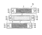
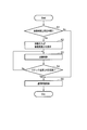
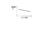
- FIG. It is an exploded top view of a fuel cell. It is a top view of a fuel cell. It is a flowchart of embodiment of the operation method of a fuel cell system. It is a graph which shows the time change of the nitrogen gas concentration in an anode channel. It is a basic map for calculating
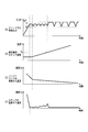
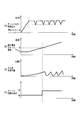
- (A) a graph showing the relationship between time and anode gas supply pressure in normal pulsation control according to generated water, (b) a graph showing the relationship between time and stack temperature, and (c) a relationship between time and the amount of generated water in the cell.
- 2 is a graph showing a relationship between (d) time and anode channel generation water.
- FIG. 1 shows a fuel cell system to which an embodiment of a fuel cell system operation method can be applied.
- This fuel cell system is an anode gas non-circulation system in which anode gas is circulated in one direction from the supply side to the discharge side.
- the fuel cell system includes a fuel cell stack FS configured by stacking a plurality of (unit) fuel cell cells FC.
- the fuel cell stack FS includes a cathode gas (oxidant gas) supply path 31 and a discharge path 32, an anode gas (fuel gas [hydrogen gas]: hydrogen gas) supply path 33, and a discharge path 34. And a cooling fluid circuit 35 is connected.
- the fuel cell FC includes a membrane electrode structure 2 having a frame 1 around it and two separators sandwiching the frame 1 and the membrane electrode structure 2 3 is provided.
- the frame 1 is integrated with the membrane electrode structure 2 by resin molding (for example, injection molding).
- the frame 1 has a rectangular shape with the membrane electrode structure 2 arranged in the center.
- three manifold holes H1 to H6 are formed.
- a region between the manifold hole and the membrane electrode structure 2 is a diffuser section [diffuser section] D described later.
- the membrane electrode structure 2 is generally called MEA (Membrane Electrode Assembly).
- MEA Membrane Electrode Assembly
- an electrolyte layer composed of a solid polymer [electrolyte layer] is a fuel electrode layer (anode) and air. It has a structure sandwiched between oxidant-electrode-layer (cathode).
- Each separator 3 has a rectangular shape having vertical and horizontal dimensions substantially equal to those of the frame 1, and provides a cathode gas channel and an anode gas channel between the frame 1 and the membrane electrode structure 2.
- the separator 3 is formed by press-molding a metal plate such as stainless steel, and the central portion corresponding to the membrane electrode structure 2 is formed in a wave shape in the short-side cross section. This wave shape is continuously formed along the long side direction, its inner surface convex portion is in contact with the membrane electrode structure 2, and its inner surface concave portion forms a gas flow path.
- manifold holes H1 to H6 equivalent to the manifold holes H1 to H6 of the frame 1 are also formed at both ends of each separator 3, respectively.
- a region between the manifold hole and the corrugated portion is a diffuser portion D described later.
- the fuel cell FC is configured by superimposing the frame 1 and the membrane electrode structure 2 and the pair of separators 3. As shown in FIG. 3, the fuel cell FC includes a power generation section [power section] G that is a region of the membrane electrode structure 2 at the center thereof. On both sides of the power generation section G, there are provided a manifold section M for supplying or discharging the reaction gas [reactant gas] and a diffuser section D between the manifold section M and the power generation section G. Yes.
- the manifold holes H1 to H6 each form a flow path in the stacking direction.
- the manifold hole H1 forms a cathode gas supply channel
- the manifold hole H2 forms a cooling fluid supply channel
- the manifold hole H3 forms an anode gas supply channel.
- the manifold hole H4 forms an anode gas discharge channel
- the manifold hole H4 forms a cooling fluid discharge channel
- the manifold hole H6 has a cathode gas discharge channel.
- a part or all of the supply flow path and the discharge flow path may be arranged in a reverse positional relationship.
- a plurality of the above-described fuel cells FC are stacked as shown in FIG. 1 and end plates E are attached on both sides to constitute a fuel cell stack FS.
- a predetermined contact surface pressure is applied to each fuel cell FC by pressurizing the fuel cells FC stacked by the elastic body attached to one end plate E in the stacking direction. Therefore, the gas sealability, conductivity, etc. are maintained well.
- an air supply unit [air31supply unit] 36 such as a compressor and a humidifier that humidifies the supply air from the air supply unit 36 are provided on the cathode gas supply path 31 [ humidifier] 37.
- the cathode gas discharge path 32 supplies water vapor contained in the cathode gas (cathode-off-gas) discharged from the fuel cell stack FS to the humidifier 37, and back pressure downstream of the humidifier 37.
- the cathode off-gas is released to the atmosphere via a regulating valve [back pressure regulation valve] 38.
- the anode gas supply path 33 is provided from the hydrogen tank 39 to the fuel cell stack FS, and a hydrogen regulating valve 40 and a hydrogen pressure sensor 41 are provided in the middle thereof.
- the hydrogen tank 39, the anode gas supply path 33, the hydrogen regulating valve 40, and the hydrogen pressure sensor 41 function as an anode gas supplier that supplies anode gas (hydrogen gas) to the fuel cell stack FS.
- the cathode gas discharge path 34 is provided from the fuel cell stack FS to the buffer tank 42.
- the anode gas (anode off-gas) discharged from the fuel cell stack FS contains impurity gas such as nitrogen gas or water vapor, so that the cathode off gas passes through the cathode gas discharge path 34 to the buffer tank 42. Discharged.
- the buffer tank 42 includes a level sensor 43 for detecting the amount of water stored therein, a drain valve 44 for discharging the water to the outside, and a nitrogen purge for releasing nitrogen gas to the atmosphere. And a valve 45.
- the cooling fluid circulation path 35 circulates the cooling fluid cooled by the radiator 46.
- a circulation pump 47 and a three-way valve 49 are provided on the cooling fluid circulation path 35.
- a bypass path 48 that bypasses the radiator 46 is connected to the cooling fluid circulation path 35, and the three-way valve 49 is disposed at a connection point between the upstream end of the bypass path 48 and the circulation path 35.
- the fuel cell stack FS is provided with a stack temperature detector (temperature sensor [temperature sensor]) 50 for detecting the internal temperature (stack temperature).
- the fuel cell system further includes a controller 51 for controlling the air supplier 36, the hydrogen regulating valve 40, the drain valve 44, the nitrogen purge valve 45, the circulation pump 47, the three-way valve 49, and the like.
- the controller 51 stores control programs for various devices, and the controller 51 includes a start control unit 52 for executing the operation method of the present embodiment and a timer 53 for measuring the system stop time.
- the controller 51 receives detection signals from the hydrogen pressure sensor 41, the level sensor 43, and the stack temperature detector 50, the current value of the fuel cell stack FS, the current value of each fuel cell FC, and the like.
- the start control unit 52 stores data indicating the relationship between the stack temperature and the amount of impurity gas generated, a supply pressure map for the anode gas, and the like.
- the supply pressure map is a reference map that appropriately sets the supply pressure of the anode gas according to the temperature and load of the fuel cell stack FS.
- the operating temperature range of the fuel cell stack FS is assumed to be ⁇ 20 to 80 ° C. in consideration of the operating temperature of the fuel cell stack FS (about 80 ° C.) and standing in a sub-freezing environment for a long time. ing. Detection is possible by estimating the nitrogen gas concentration based on the stack temperature. Further, it is possible to indirectly estimate the stack temperature and nitrogen gas concentration at the time of startup based on the atmospheric temperature, the system shutdown time, and the like.
- the activation control unit 52 of the controller 51 has a function of detecting the nitrogen gas concentration in the fuel cell stack FS and the buffer tank 42 by estimation, and functions as an impurity gas concentration detector. That is, the activation control unit 52 estimates and detects the nitrogen gas concentration using various data stored in advance.
- the activation control is performed by using the nitrogen gas concentration detection function of the activation control unit 52.
- the startup control at least one of the pulsation pressure ⁇ P and the pulsation period ⁇ T of the anode gas is changed based on the stack temperature.
- the pulsation pressure ⁇ P is the difference between the upper limit pressure and the lower limit pressure of the pulsation (see FIG. 9A). Therefore, the setting of the pulsation pressure ⁇ P is also to set the upper limit pressure and the lower limit pressure.
- the pulsation cycle ⁇ T may be a time for maintaining the upper limit pressure (see FIG. 10A), or may be a time for one pitch including the upper limit pressure and the lower limit pressure.
- the start control and / or the pulsation cycle ⁇ T that makes the pulsation pressure ⁇ P smaller than the normal pulsation control are controlled.
- the start-up control is made longer.
- the start control and / or the pulsation cycle ⁇ T that makes the pulsation pressure ⁇ P smaller than the normal pulsation control
- the starting control is made longer.
- the operation method of the fuel cell system of this embodiment will be described with reference to the flowchart shown in FIG.
- the present embodiment can suitably cope with a problem at the start-up when the amount of residual impurity gas inside the fuel cell stack FS is large. That is, this embodiment can suitably cope with the backflow of the impurity gas due to the pulsation of the supply pressure of the anode gas at the time of starting after a long stop in a low temperature environment. Therefore, in the present embodiment, the stop time is first determined.
- step S1 When the system is activated, it is determined whether or not the stop time measured by the timer 53 is equal to or longer than a predetermined time (step S1).
- the predetermined time is set based on the above-described data stored in the activation control unit 52.
- step S5 When the stop time is less than the predetermined time (No in step S1), it is considered that the residual amount of impurity gas in the fuel cell stack FS is small, and normal pulsation control is performed to pulsate the supply pressure of the anode gas (step). S5).
- the anode gas is supplied to the fuel cell stack FS, and the impurity gas (nitrogen gas) in the fuel cell stack FS is discharged to the buffer tank 42. Since the amount of nitrogen gas remaining in the fuel cell stack FS at the time of startup is small, the amount of nitrogen gas discharged to the buffer tank 42 is small, and even if normal pulsation control is performed, the backflow from the buffer tank 42 to the fuel cell stack FS does not occur. Does not occur.
- step S1 when the stop time is equal to or longer than the predetermined time (Yes in step S1), it is considered that the residual amount of nitrogen gas in the fuel cell stack FS is large, and the pulsation pressure ⁇ P and the pulsation period ⁇ T of the anode gas are changed. Start control is performed.
- the nitrogen gas concentration in the fuel cell stack FS gradually increases after the system is stopped, but the nitrogen gas concentration is low until a predetermined time ts after the system is stopped. Therefore, when the system is restarted within the predetermined time ts, the residual amount of nitrogen gas is small even if normal pulsation control is performed, and power generation is not affected. For this reason, as described above, the stop time is determined in step S1.
- the anode flow path means all anode-side gas flow areas including the fuel cell FC, the fuel cell stack FS, and the piping system.
- step S1 the anode gas pulsation pressure ⁇ P and the pulsation period ⁇ T are set in order to perform start-up control for suppressing the backflow of nitrogen gas from the buffer tank 42 (step S2).
- values of the pulsation upper limit pressure and the pulsation lower limit pressure are acquired according to the stack temperature from the map showing the relationship between the stack temperature and the anode gas supply pressure shown in FIG.
- the pulsation period ⁇ T is obtained from the map shown in FIG.
- the reason for setting the pulsation pressure ⁇ P and the pulsation period ⁇ T of the anode gas in accordance with the temperature of the fuel cell stack FS is as follows.
- the power generation is continued while performing pulsation and purging of the anode gas, so that the nitrogen gas concentration in the buffer tank 42 is lowered and the fuel cell stack is generated by power generation.
- the temperature of FS rises. Therefore, assuming the start-up time, the nitrogen gas concentration in the buffer tank 42 can be substituted with the temperature of the fuel cell stack FS. As the temperature of the fuel cell stack FS becomes higher, the nitrogen gas concentration in the buffer tank 42 becomes thinner. Therefore, the backflow of nitrogen gas is less likely to occur, and the pulsation pressure ⁇ P can be made larger than the initial stage of startup.
- the temperature of the fuel cell stack FS is set as a substitute value of the nitrogen gas concentration (permeability), and the pulsation pressure ⁇ P is set to be larger as the temperature of the fuel cell stack FS is higher. In this way, the hydrogen partial pressure in the power generation region due to an increase in the amount of nitrogen gas (cathode offgas) permeating from the cathode side can be secured.
- the optimum pulsation pressure ⁇ P considering the nitrogen gas concentration in the buffer tank 42 and the permeation amount of nitrogen gas from the cathode side according to the temperature of the fuel cell stack FS. Can be set.
- the pulsation pressure ⁇ P is set to be smaller than that during normal pulsation control.
- the pulsation cycle ⁇ T is set to be longer than that during normal pulsation control.
- step S4 it is determined whether or not the stack temperature detected by the stack temperature detector 50 is equal to or higher than a predetermined temperature Ts (step S4).
- the stack temperature is equal to or higher than the predetermined temperature Ts (Yes in step S4), it is considered that the nitrogen gas concentration in the fuel cell stack FS (fuel cell FC) has sufficiently decreased, and the normal pulsation control is performed ( Step S5).
- step S4 when the stack temperature is lower than the predetermined temperature Ts (No in step S4), it is considered that the nitrogen gas permeation amount is small and the nitrogen gas concentration in the buffer tank 42 is not yet sufficiently lowered. Subsequently, the activation control using the pulsation pressure ⁇ P and / or the pulsation cycle ⁇ T is continued (step S3). In this way, in order to correct the pulsation condition of the anode gas, the start-up control or the normal pulsation control is switched according to the stack temperature, and the pulsation condition of the anode gas is corrected to a condition suitable for the start-up.
- the stack temperature rises due to the power generation of the fuel cell stack FS, as shown in FIG. 9B.
- the nitrogen gas concentration in the buffer tank 42 decreases.
- the nitrogen gas concentration in the buffer tank 42 is reduced by discharging the nitrogen gas in the fuel cell stack FS to the buffer tank 42 by the supplied anode gas, and further reducing the nitrogen gas in the buffer tank 42 by the nitrogen purge valve 45 by the anode off gas. This is because it is discharged to the outside.
- the nitrogen gas concentration in the fuel cell stack FS decreases rapidly with an increase in the anode gas supply pressure immediately after startup, and then a small pulsation pressure ⁇ P during startup control. Due to the pressure pulsation, a very small amount of nitrogen gas flows backward from the buffer tank 42 and slightly fluctuates. However, since the pulsation pressure ⁇ P is small, the back flow rate is very small, the nitrogen gas concentration in the fuel cell stack FS is kept low, and the nitrogen gas concentration does not affect the power generation. After the transition to the normal pulsation control, the nitrogen gas concentration in the fuel cell stack FS becomes almost zero due to sufficient discharge due to the large pulsation pressure ⁇ P. When the normal pulsation control is performed, the nitrogen gas concentration in the buffer tank 42 is low, and the nitrogen gas does not flow backward from the buffer tank 42 even if the pulsation pressure ⁇ P is increased.
- the stack temperature rises due to the power generation of the fuel cell stack FS as shown in FIG. 10 (b).
- the nitrogen gas concentration in the buffer tank 42 decreases (the reason is described above).
- the nitrogen gas concentration in the fuel cell stack FS rapidly decreases with an increase in the anode gas supply pressure immediately after startup, and then has a long pulsation period ⁇ T during startup control. Due to the pressure pulsation, a very small amount of nitrogen gas flows backward from the buffer tank 42 and slightly fluctuates.
- the nitrogen gas concentration in the fuel cell stack FS is kept low, and the nitrogen gas concentration does not affect power generation. Then, after shifting to normal pulsation control, the nitrogen gas concentration in the fuel cell stack FS becomes substantially zero by sufficient discharge with a short pulsation period ⁇ T.
- the normal pulsation control is performed, the nitrogen gas concentration in the buffer tank 42 is low, and the nitrogen gas does not flow back from the buffer tank 42 even if the pulsation cycle ⁇ T is shortened.
- the concentration of the impurity gas (mainly nitrogen gas) in the buffer tank 42 is detected, and the pulsation pressure ⁇ P and / or the pulsation period ⁇ T of the anode gas is the normal pulsation control. Different activation control is performed. Therefore, the impurity gas can be removed while the hydrogen gas concentration in the fuel cell stack FS is sufficiently secured by reducing the reverse flow rate of the impurity gas from the buffer tank 42 at the time of starting after a long stop. Further, according to the impurity gas concentration detection method described above, it is possible to perform control with a minimum of sensors, and to simplify the system.
- the back flow rate of the impurity gas from the buffer tank 42 is small, so the hydrogen content in each fuel cell FC is Insufficient pressure is eliminated, and voltage drop and deterioration of the fuel cell FC can be prevented.
- the anode gas supply pressure based on the stack temperature, it is possible to perform more accurate control according to the state of the fuel cell stack FS at the time of startup. Furthermore, even when the anode gas supply pressure is controlled based on the system stop time, more accurate control can be performed according to the state of the fuel cell stack FS at the time of startup.
- Step S5 when the stack temperature becomes equal to or higher than the predetermined temperature Ts during the start-up control (Yes in Step S4), the normal pulsation control is performed (Step S5). However, after a predetermined time has elapsed from the start, the start control may be shifted to the normal pulsation control.
- start control for gradually increasing the pulsation pressure ⁇ P and start control for gradually shortening the pulsation period ⁇ T can be performed as the stack temperature detected by the stack temperature detector 50 increases.
- the pulsation pressure ⁇ P during the start-up control is gradually increased as the stack temperature rises.
- the nitrogen gas concentration in the fuel cell stack FS decreases rapidly with an increase in the anode gas supply pressure immediately after startup, and then has a small pulsation pressure ⁇ P immediately after startup. Due to the pressure pulsation, a very small amount of nitrogen gas flows backward from the buffer tank 42 and slightly fluctuates. However, since the pulsation pressure ⁇ P is small, the back flow rate is very small, the nitrogen gas concentration in the fuel cell stack FS is kept low, and the nitrogen gas concentration does not affect the power generation. Thereafter, the pulsation pressure ⁇ P is gradually increased as the nitrogen gas concentration in the buffer tank 42 decreases.
- the pulsation period ⁇ T during the start-up control is gradually shortened as the stack temperature rises.
- the nitrogen gas concentration in the fuel cell stack FS decreases rapidly with an increase in the anode gas supply pressure immediately after startup, and then has a long pulsation period ⁇ T immediately after startup. Due to the pressure pulsation, a very small amount of nitrogen gas flows backward from the buffer tank 42 and slightly fluctuates. However, since the pulsation cycle ⁇ T is long, the back flow rate is very small (the back flow frequency is low), the nitrogen gas concentration in the fuel cell stack FS is kept low, and the nitrogen gas concentration does not affect the power generation. Thereafter, as the nitrogen gas concentration in the buffer tank 42 decreases, the pulsation cycle ⁇ T is gradually shortened (the backflow frequency increases).
- the pulsation pressure control shown in FIG. 9 can be performed simultaneously with the pulsation pressure control of FIG. 10 or FIG.
- the pulsation pressure control shown in FIG. 11 can be performed simultaneously with the pulsation pressure control of FIG. 10 or FIG.
- the activation control unit 52 of the controller 51 functions as a generated water estimator that detects generation of generated water in the anode flow path by estimation.
- the generation of generated water in the anode flow path is detected.
- the routine proceeds to normal pulsation control.
- the pulsation pressure ⁇ P and / or the pulsation cycle ⁇ T are kept constant.
- the stack temperature rises due to the power generation of the fuel cell stack FS as shown in FIG. 13B, and the amount of water generated in the fuel cell FC increases with the power generation as shown in FIG. 13C.
- the generated water is discharged from the fuel cell stack FS by normal pulsation control.
- the impurity gas is removed while preventing the backflow of the impurity gas from the buffer tank 42 and ensuring the hydrogen gas concentration in the fuel cell stack FS sufficiently at the time of startup after a long stop. be able to.
- the operation method of the fuel cell system is not limited to the above embodiment.
- a nitrogen gas detector 54 that detects the nitrogen gas concentration in the buffer tank 42 may be provided as shown by a dotted line in FIG.
- a nitrogen gas sensor is used as the nitrogen gas detector 54.
- the nitrogen gas concentration detected by the nitrogen gas detector 54 is used for control.
- a nitrogen gas detector 55 for detecting the nitrogen gas concentration on the anode side of the fuel cell stack FS may be provided.
- a nitrogen gas sensor is used as the nitrogen gas detector 55. In this case, not the estimated nitrogen gas concentration but the nitrogen gas concentration detected by the nitrogen gas detector 55 is used for control.
- the nitrogen gas concentration in the buffer tank 42 and the fuel cell stack FS is actually measured by the nitrogen gas detector 54 and the nitrogen gas detector 55, it is possible to perform highly accurate control corresponding to the state of the fuel cell system at the time of startup. it can.
- the concentration of the anode gas is “hydrogen concentration ⁇ 100 ⁇ nitrogen concentration ⁇ water vapor concentration”.
- the water vapor concentration can be estimated to some extent from the operating state of the fuel cell. That is, if the nitrogen concentration is known, the hydrogen concentration can be known, so that the nitrogen gas concentration can be estimated using a hydrogen concentration sensor. Therefore, a hydrogen gas detector can be used in place of the nitrogen gas detector 54 and the nitrogen gas detector 55.
Landscapes
- Life Sciences & Earth Sciences (AREA)
- Engineering & Computer Science (AREA)
- Manufacturing & Machinery (AREA)
- Sustainable Development (AREA)
- Sustainable Energy (AREA)
- Chemical & Material Sciences (AREA)
- Chemical Kinetics & Catalysis (AREA)
- Electrochemistry (AREA)
- General Chemical & Material Sciences (AREA)
- Fuel Cell (AREA)
Abstract
Description
Claims (8)
- アノードガス非循環型の燃料電池システムであって、
複数の燃料電池セルを積層して構成された燃料電池スタックと、
前記燃料電池スタックから排出されたアノードオフガスに含まれる不純物ガスを外部に排出するためのバッファタンクと、
前記バッファタンクの内部の不純物ガス濃度を検出する不純物ガス濃度検出部と、
前記燃料電池スタックにアノードガスを供給するアノードガス供給器と、を備え、
前記アノードガス供給器によって供給圧力を脈動させつつ前記燃料電池スタック内の不純物ガスを前記バッファタンクに圧送する際に、前記不純物ガス濃度検出部によって検出された前記バッファタンク内の不純物ガス濃度に応じて、アノードガス供給時の脈動圧力及び脈動周期のうちの少なくとも一方を前記アノードガス供給器によって変化させて起動制御が行われる、ことを特徴とする燃料電池システム。 - 複数の燃料電池セルを積層して構成された燃料電池スタックと、前記燃料電池スタックから排出されたアノードオフガスに含まれる不純物ガスを外部に排出するためのバッファタンクとを備え、前記燃料電池スタックへのアノードガスの供給圧力を脈動させることによって前記燃料電池スタック内の不純物ガスを前記バッファタンクに圧送する構造を有するアノードガス非循環型の燃料電池システムの運転方法であって、
前記燃料電池システムが、前記バッファタンクの内部の不純物ガス濃度を検出する不純物ガス濃度検出器をさらに備えており、
前記不純物ガス濃度検出器によって検出された前記バッファタンク内の不純物ガス濃度に応じて、前記燃料電池スタックに供給されるアノードガスの脈動圧力及び脈動周期のうちの少なくとも一方を変化させる起動制御を行う、燃料電池システムの運転方法。 - 前記不純物ガス濃度検出器が、前記燃料電池スタックの温度を検出するスタック温度検出器であり、前記スタック温度検出器によって検出された前記燃料電池スタックの温度が所定温度未満である場合に、前記脈動圧力を小さく設定する、請求項2に記載の燃料電池システムの運転方法。
- 前記起動制御中において、前記脈動圧力を徐々に大きくする、請求項3に記載の燃料電池システムの運転方法。
- 前記不純物ガス濃度検出器が、前記燃料電池スタックの温度を検出するスタック温度検出器であり、前記スタック温度検出器によって検出された前記燃料電池スタックの温度が所定温度未満である場合に、前記脈動周期を長く設定する、請求項2~4のいずれかに記載の燃料電池システムの運転方法。
- 前記起動制御中において、前記脈動周期を徐々に短くする、請求項5に記載の燃料電池システムの運転方法。
- 前記燃料電池システムが、当該燃料電池システムの停止時間を計測するタイマをさらに備えており、前記タイマによって計測された停止時間が所定時間以上である場合に、前記起動制御を実行する、請求項2~6のいずれかに記載の燃料電池システムの運転方法。
- 前記燃料電池システムが、アノード流路での生成水の有無を検出する生成水検出器をさらに備えており、前記生成水検出器によって生成水が検出された場合に、前記脈動圧力及び前記脈動周期の少なくとも一方を一定に維持する通常脈動制御を行う、請求項2~7のいずれかに記載の燃料電池システムの運転方法。
Priority Applications (5)
| Application Number | Priority Date | Filing Date | Title |
|---|---|---|---|
| JP2012532950A JP5549735B2 (ja) | 2010-09-09 | 2011-09-01 | 燃料電池システム及びその運転方法 |
| CN201180043508.4A CN103098280B (zh) | 2010-09-09 | 2011-09-01 | 燃料电池系统及其运转方法 |
| CA2810657A CA2810657C (en) | 2010-09-09 | 2011-09-01 | Fuel cell system and operating method thereof |
| US13/821,170 US9166233B2 (en) | 2010-09-09 | 2011-09-01 | Fuel cell system and operating method thereof |
| EP11823479.8A EP2615676B1 (en) | 2010-09-09 | 2011-09-01 | Fuel cell system and method for operating same |
Applications Claiming Priority (2)
| Application Number | Priority Date | Filing Date | Title |
|---|---|---|---|
| JP2010-202267 | 2010-09-09 | ||
| JP2010202267 | 2010-09-09 |
Publications (1)
| Publication Number | Publication Date |
|---|---|
| WO2012033003A1 true WO2012033003A1 (ja) | 2012-03-15 |
Family
ID=45810605
Family Applications (1)
| Application Number | Title | Priority Date | Filing Date |
|---|---|---|---|
| PCT/JP2011/069912 Ceased WO2012033003A1 (ja) | 2010-09-09 | 2011-09-01 | 燃料電池システム及びその運転方法 |
Country Status (6)
| Country | Link |
|---|---|
| US (1) | US9166233B2 (ja) |
| EP (1) | EP2615676B1 (ja) |
| JP (1) | JP5549735B2 (ja) |
| CN (1) | CN103098280B (ja) |
| CA (1) | CA2810657C (ja) |
| WO (1) | WO2012033003A1 (ja) |
Cited By (6)
| Publication number | Priority date | Publication date | Assignee | Title |
|---|---|---|---|---|
| JP2013201085A (ja) * | 2012-03-26 | 2013-10-03 | Honda Motor Co Ltd | 燃料電池 |
| US20140093803A1 (en) * | 2011-06-02 | 2014-04-03 | Nissan Motor Co., Ltd. | Fuel cell system |
| WO2014192649A1 (ja) * | 2013-05-30 | 2014-12-04 | 日産自動車株式会社 | 燃料電池システム及び燃料電池システムの制御方法 |
| WO2014192486A1 (ja) * | 2013-05-30 | 2014-12-04 | 日産自動車株式会社 | 燃料電池システム |
| WO2015001845A1 (ja) * | 2013-07-05 | 2015-01-08 | 日産自動車株式会社 | 燃料電池システム及び燃料電池システムの制御方法 |
| JP2019160557A (ja) * | 2018-03-13 | 2019-09-19 | 株式会社デンソー | 燃料電池システム |
Families Citing this family (9)
| Publication number | Priority date | Publication date | Assignee | Title |
|---|---|---|---|---|
| KR101459849B1 (ko) * | 2012-12-14 | 2014-11-07 | 현대자동차주식회사 | 연료전지 시스템의 맥동 운전 방법 |
| GB2518680A (en) * | 2013-09-30 | 2015-04-01 | Intelligent Energy Ltd | Water removal in a fuel cell |
| CA2965901C (en) * | 2014-10-28 | 2022-03-01 | Nissan Motor Co., Ltd. | Purge amount of anode off-gas computation system in fuel cell system |
| JP7016025B2 (ja) * | 2016-11-28 | 2022-02-04 | パナソニックIpマネジメント株式会社 | 燃料電池システムおよびその運転方法 |
| CN109962266B (zh) * | 2017-12-25 | 2024-06-21 | 宇通客车股份有限公司 | 一种燃料电池氢气供应子系统及燃料电池系统 |
| DE102019200727A1 (de) | 2019-01-22 | 2020-07-23 | Audi Ag | Verfahren zum Betreiben einer Brennstoffzellenvorrichtung, Brennstoffzellenvorrichtung sowie Kraftfahrzeug |
| CN112820901B (zh) * | 2020-12-31 | 2022-04-12 | 华中科技大学 | 一种解决封闭环境中氢氧燃料电池水淹问题的方法 |
| CN115224317B (zh) * | 2021-05-31 | 2024-07-09 | 广州汽车集团股份有限公司 | 燃料电池系统的管理方法、燃料电池系统及存储介质 |
| JP2023115601A (ja) * | 2022-02-08 | 2023-08-21 | 本田技研工業株式会社 | 燃料電池スタックの活性化方法及びその装置 |
Citations (4)
| Publication number | Priority date | Publication date | Assignee | Title |
|---|---|---|---|---|
| JP2008097966A (ja) | 2006-10-11 | 2008-04-24 | Toyota Motor Corp | 燃料電池システム、および、その制御方法 |
| JP2008176975A (ja) * | 2007-01-17 | 2008-07-31 | Toyota Motor Corp | 燃料電池システム |
| JP2010123501A (ja) * | 2008-11-21 | 2010-06-03 | Nissan Motor Co Ltd | 燃料電池システム |
| JP2010202267A (ja) | 2009-03-05 | 2010-09-16 | Fuji Seal International Inc | スパウト付きスタンディングパウチ |
Family Cites Families (3)
| Publication number | Priority date | Publication date | Assignee | Title |
|---|---|---|---|---|
| JP2005158509A (ja) * | 2003-11-26 | 2005-06-16 | Nissan Motor Co Ltd | 燃料電池システム |
| US20050260463A1 (en) * | 2004-05-21 | 2005-11-24 | Chapman Ivan D | Fluid flow pulsing for increased stability in PEM fuel cell |
| CN101409353B (zh) * | 2008-11-12 | 2012-01-25 | 同济大学 | 燃料电池汽车氢气安全排放用尾气处理方法及装置 |
-
2011
- 2011-09-01 CN CN201180043508.4A patent/CN103098280B/zh active Active
- 2011-09-01 JP JP2012532950A patent/JP5549735B2/ja active Active
- 2011-09-01 CA CA2810657A patent/CA2810657C/en active Active
- 2011-09-01 WO PCT/JP2011/069912 patent/WO2012033003A1/ja not_active Ceased
- 2011-09-01 EP EP11823479.8A patent/EP2615676B1/en active Active
- 2011-09-01 US US13/821,170 patent/US9166233B2/en active Active
Patent Citations (4)
| Publication number | Priority date | Publication date | Assignee | Title |
|---|---|---|---|---|
| JP2008097966A (ja) | 2006-10-11 | 2008-04-24 | Toyota Motor Corp | 燃料電池システム、および、その制御方法 |
| JP2008176975A (ja) * | 2007-01-17 | 2008-07-31 | Toyota Motor Corp | 燃料電池システム |
| JP2010123501A (ja) * | 2008-11-21 | 2010-06-03 | Nissan Motor Co Ltd | 燃料電池システム |
| JP2010202267A (ja) | 2009-03-05 | 2010-09-16 | Fuji Seal International Inc | スパウト付きスタンディングパウチ |
Cited By (11)
| Publication number | Priority date | Publication date | Assignee | Title |
|---|---|---|---|---|
| US20140093803A1 (en) * | 2011-06-02 | 2014-04-03 | Nissan Motor Co., Ltd. | Fuel cell system |
| US9812718B2 (en) * | 2011-06-02 | 2017-11-07 | Nissan Motor Co., Ltd. | Fuel cell system |
| US10193168B2 (en) | 2011-06-02 | 2019-01-29 | Nissan Motor Co., Ltd. | Fuel cell system |
| JP2013201085A (ja) * | 2012-03-26 | 2013-10-03 | Honda Motor Co Ltd | 燃料電池 |
| WO2014192649A1 (ja) * | 2013-05-30 | 2014-12-04 | 日産自動車株式会社 | 燃料電池システム及び燃料電池システムの制御方法 |
| WO2014192486A1 (ja) * | 2013-05-30 | 2014-12-04 | 日産自動車株式会社 | 燃料電池システム |
| WO2015001845A1 (ja) * | 2013-07-05 | 2015-01-08 | 日産自動車株式会社 | 燃料電池システム及び燃料電池システムの制御方法 |
| JP6083472B2 (ja) * | 2013-07-05 | 2017-02-22 | 日産自動車株式会社 | 燃料電池システム及び燃料電池システムの制御方法 |
| US10256484B2 (en) | 2013-07-05 | 2019-04-09 | Nissan Motor Co., Ltd. | Fuel cell system and method for controlling fuel cell system |
| JP2019160557A (ja) * | 2018-03-13 | 2019-09-19 | 株式会社デンソー | 燃料電池システム |
| JP7155550B2 (ja) | 2018-03-13 | 2022-10-19 | 株式会社デンソー | 燃料電池システム |
Also Published As
| Publication number | Publication date |
|---|---|
| EP2615676A1 (en) | 2013-07-17 |
| JP5549735B2 (ja) | 2014-07-16 |
| EP2615676B1 (en) | 2017-06-21 |
| US9166233B2 (en) | 2015-10-20 |
| US20130164649A1 (en) | 2013-06-27 |
| CN103098280B (zh) | 2015-02-04 |
| CN103098280A (zh) | 2013-05-08 |
| JPWO2012033003A1 (ja) | 2014-01-20 |
| EP2615676A4 (en) | 2016-11-16 |
| CA2810657A1 (en) | 2012-03-15 |
| CA2810657C (en) | 2014-12-16 |
Similar Documents
| Publication | Publication Date | Title |
|---|---|---|
| JP5549735B2 (ja) | 燃料電池システム及びその運転方法 | |
| CN103081196B (zh) | 燃料电池系统的运转方法 | |
| KR101054140B1 (ko) | 연료 전지 시스템 | |
| JP4997804B2 (ja) | 燃料電池システム | |
| JP5596758B2 (ja) | 燃料電池システム及びその制御方法 | |
| JP6149475B2 (ja) | 燃料電池システム | |
| JP2005174855A (ja) | 燃料電池システム | |
| JP2007184202A (ja) | 燃料電池システム | |
| JP4923426B2 (ja) | 燃料電池システム | |
| JP5304863B2 (ja) | 燃料電池システム | |
| JP2005243491A (ja) | 燃料電池システム | |
| JP4529387B2 (ja) | 燃料電池システム | |
| JP4982977B2 (ja) | 燃料電池システム | |
| JP2006040610A (ja) | 燃料電池システム | |
| JP2012059557A (ja) | 燃料電池システム | |
| JP2011204447A (ja) | 燃料電池システム | |
| JP5557579B2 (ja) | 燃料電池システム | |
| JP5509728B2 (ja) | 燃料電池システム | |
| JP2008269898A (ja) | 燃料電池システム及びその制御方法 | |
| JP5217123B2 (ja) | 燃料電池システム | |
| JP2008117719A (ja) | 燃料電池システム | |
| JP2012155982A (ja) | 燃料電池システムおよび燃料電池システムの制御方法 |
Legal Events
| Date | Code | Title | Description |
|---|---|---|---|
| WWE | Wipo information: entry into national phase |
Ref document number: 201180043508.4 Country of ref document: CN |
|
| 121 | Ep: the epo has been informed by wipo that ep was designated in this application |
Ref document number: 11823479 Country of ref document: EP Kind code of ref document: A1 |
|
| ENP | Entry into the national phase |
Ref document number: 2810657 Country of ref document: CA |
|
| REEP | Request for entry into the european phase |
Ref document number: 2011823479 Country of ref document: EP |
|
| WWE | Wipo information: entry into national phase |
Ref document number: 13821170 Country of ref document: US Ref document number: 2011823479 Country of ref document: EP |
|
| ENP | Entry into the national phase |
Ref document number: 2012532950 Country of ref document: JP Kind code of ref document: A |
|
| NENP | Non-entry into the national phase |
Ref country code: DE |