WO2012035728A1 - 画像復号装置、画像符号化装置、それらの方法、プログラム、集積回路およびトランスコード装置 - Google Patents
画像復号装置、画像符号化装置、それらの方法、プログラム、集積回路およびトランスコード装置 Download PDFInfo
- Publication number
- WO2012035728A1 WO2012035728A1 PCT/JP2011/005063 JP2011005063W WO2012035728A1 WO 2012035728 A1 WO2012035728 A1 WO 2012035728A1 JP 2011005063 W JP2011005063 W JP 2011005063W WO 2012035728 A1 WO2012035728 A1 WO 2012035728A1
- Authority
- WO
- WIPO (PCT)
- Prior art keywords
- decoding
- information
- image data
- unit
- storage unit
- Prior art date
- Legal status (The legal status is an assumption and is not a legal conclusion. Google has not performed a legal analysis and makes no representation as to the accuracy of the status listed.)
- Ceased
Links
Images


















Classifications
-
- H—ELECTRICITY
- H04—ELECTRIC COMMUNICATION TECHNIQUE
- H04N—PICTORIAL COMMUNICATION, e.g. TELEVISION
- H04N19/00—Methods or arrangements for coding, decoding, compressing or decompressing digital video signals
- H04N19/42—Methods or arrangements for coding, decoding, compressing or decompressing digital video signals characterised by implementation details or hardware specially adapted for video compression or decompression, e.g. dedicated software implementation
- H04N19/436—Methods or arrangements for coding, decoding, compressing or decompressing digital video signals characterised by implementation details or hardware specially adapted for video compression or decompression, e.g. dedicated software implementation using parallelised computational arrangements
-
- H—ELECTRICITY
- H04—ELECTRIC COMMUNICATION TECHNIQUE
- H04N—PICTORIAL COMMUNICATION, e.g. TELEVISION
- H04N19/00—Methods or arrangements for coding, decoding, compressing or decompressing digital video signals
- H04N19/10—Methods or arrangements for coding, decoding, compressing or decompressing digital video signals using adaptive coding
- H04N19/134—Methods or arrangements for coding, decoding, compressing or decompressing digital video signals using adaptive coding characterised by the element, parameter or criterion affecting or controlling the adaptive coding
- H04N19/157—Assigned coding mode, i.e. the coding mode being predefined or preselected to be further used for selection of another element or parameter
- H04N19/16—Assigned coding mode, i.e. the coding mode being predefined or preselected to be further used for selection of another element or parameter for a given display mode, e.g. for interlaced or progressive display mode
-
- H—ELECTRICITY
- H04—ELECTRIC COMMUNICATION TECHNIQUE
- H04N—PICTORIAL COMMUNICATION, e.g. TELEVISION
- H04N19/00—Methods or arrangements for coding, decoding, compressing or decompressing digital video signals
- H04N19/40—Methods or arrangements for coding, decoding, compressing or decompressing digital video signals using video transcoding, i.e. partial or full decoding of a coded input stream followed by re-encoding of the decoded output stream
-
- H—ELECTRICITY
- H04—ELECTRIC COMMUNICATION TECHNIQUE
- H04N—PICTORIAL COMMUNICATION, e.g. TELEVISION
- H04N19/00—Methods or arrangements for coding, decoding, compressing or decompressing digital video signals
- H04N19/44—Decoders specially adapted therefor, e.g. video decoders which are asymmetric with respect to the encoder
-
- H—ELECTRICITY
- H04—ELECTRIC COMMUNICATION TECHNIQUE
- H04N—PICTORIAL COMMUNICATION, e.g. TELEVISION
- H04N19/00—Methods or arrangements for coding, decoding, compressing or decompressing digital video signals
- H04N19/50—Methods or arrangements for coding, decoding, compressing or decompressing digital video signals using predictive coding
-
- H—ELECTRICITY
- H04—ELECTRIC COMMUNICATION TECHNIQUE
- H04N—PICTORIAL COMMUNICATION, e.g. TELEVISION
- H04N19/00—Methods or arrangements for coding, decoding, compressing or decompressing digital video signals
- H04N19/50—Methods or arrangements for coding, decoding, compressing or decompressing digital video signals using predictive coding
- H04N19/593—Methods or arrangements for coding, decoding, compressing or decompressing digital video signals using predictive coding involving spatial prediction techniques
-
- H—ELECTRICITY
- H04—ELECTRIC COMMUNICATION TECHNIQUE
- H04N—PICTORIAL COMMUNICATION, e.g. TELEVISION
- H04N19/00—Methods or arrangements for coding, decoding, compressing or decompressing digital video signals
- H04N19/80—Details of filtering operations specially adapted for video compression, e.g. for pixel interpolation
- H04N19/82—Details of filtering operations specially adapted for video compression, e.g. for pixel interpolation involving filtering within a prediction loop
Definitions
- the present invention relates to an image decoding apparatus that decodes an encoded image, an image encoding apparatus that encodes an image, and the like, and in particular, an image decoding apparatus that executes decoding in parallel and an image that executes encoding in parallel.
- the present invention relates to an encoding device and the like.
- An image encoding device that encodes a moving image divides each picture constituting the moving image into macro blocks each having 16 ⁇ 16 pixels, and encodes the moving image for each macro block. Then, the image encoding device generates an encoded stream indicating the encoded moving image.
- the image decoding apparatus decodes the encoded stream in units of macroblocks and reproduces each picture of the original moving image.
- ITU-T International Telecommunication Union Telecommunication Standardization Sector
- H.264 as one of the conventional encoding methods.
- H.264 standards see, for example, Non-Patent Document 1.
- H. In the H.264 standard, a variable length code is adopted, and in the variable length code, each macroblock is encoded in a variable length.
- H.C. In the H.264 standard, in each process such as in-plane prediction, motion vector calculation, and deblock filter processing, data is transferred between a macroblock to be encoded or decoded and another macroblock adjacent to the macroblock. There are dependencies.
- FIG. 47 is a diagram showing data dependency.
- pixels in macroblocks MBa to MBd adjacent to the decoding target macroblock MBx are used for in-plane prediction of the decoding target macroblock MBx.
- the motion vectors of the macroblocks MBa to MBc adjacent to the decoding target macroblock MBx are used.
- pixels of the macroblocks MBa and MBb adjacent to the decoding target macroblock MBx are used.
- Patent Document 1 Some prior arts solve such problems (see, for example, Patent Document 1).
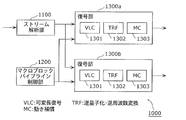
- FIG. 48A is a configuration diagram showing the configuration of the image decoding device in Patent Document 1.
- each of the decoding units 1300a and 1300b includes a VCL 1301 that performs variable length decoding, a TRF 1302 that performs inverse quantization and inverse frequency conversion, and an MC 1303 that performs motion compensation. That is, each of the decoding units 1300a and 1300b decodes a macroblock to be decoded (inter-screen predictive decoding) by performing variable length decoding, inverse quantization and inverse frequency conversion, and motion compensation.
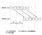
- FIG. 48B is an explanatory diagram for explaining the operation of the image decoding apparatus 1000 in Patent Document 1.
- the macroblock pipeline control unit 1200 sets the position of the macroblock decoded by the decoding units 1300a and 1300b to 2 macroblocks in the horizontal direction (1 macroblock in the vertical direction). Shift. Further, the macroblock pipeline control unit 1200 performs a decoding partial process for each of the two decoding target macroblocks (a process of any one of variable length decoding, inverse quantization and inverse frequency conversion, and motion compensation). For each TS (time slot) time, the decoding units 1300a and 1300b are executed within the TS time.
- the macroblock pipeline control unit 1200 operates so that the decoding units 1300a and 1300b decode one macroblock within a predetermined period, in other words, in synchronization with each macroblock. Next, the decoding units 1300a and 1300b are controlled. As a result, decoding by parallel processing is performed while maintaining data dependency.
- Patent Document 1 has a problem that it prevents the improvement of decoding efficiency and is difficult to realize.
- each decoding unit 1300a and 1300b decodes one TS time.
- the TS time In accordance with the longer time. If there are three or more decoding units, it is necessary to design the TS time as the longest time required for the partial decoding process of each decoding unit. Therefore, the larger the number of decoding units, the more the improvement in decoding efficiency is hindered. It is done.
- an object of the present invention is to solve the above-described problem, and to provide an image decoding apparatus and an image encoding apparatus that can be easily realized while improving decoding efficiency or encoding efficiency.
- an image decoding apparatus is an image decoding apparatus that decodes encoded image data, the first storage unit storing the encoded image data, A dividing unit that generates first and second encoded image data by dividing the encoded image data; a second storage unit that stores the first encoded image data; and the second A third storage unit that stores encoded image data, a frame storage unit, and first and second units that decode the first and second encoded image data in parallel and store them in the frame storage unit And an information storage unit for storing first and second decoding result information used for decoding by the first and second decoding units, wherein the first decoding unit includes the information The second decryption result stored in the storage unit
- the first encoded image data is decoded using information, a part of the information generated by the decoding is stored in the information storage unit as the first decoding result information, and the second decoding unit is The second encoded image data is decoded using the first decoding result information stored in the information storage unit, and a part of the
- the encoded image data (encoded stream) is divided into first and second encoded image data (divided streams), and the first and second encoded image data are respectively the first and second encoded images. Since decoding is performed in parallel by the decoding unit, it is possible to omit the macroblock pipeline control unit as in Patent Document 1 that centrally controls the timing of decoding by each decoding unit. Furthermore, even when the image decoding apparatus includes a large number of decoding units for dividing the encoded image data into three or more data and decoding these data in parallel, the macro as described in Patent Document 1 above. It is not necessary to lay a signal line between the block line control unit and each decoding unit, and the image decoding apparatus can be easily realized.
- the The first and second decoding result information (peripheral information) required by data dependency in the H.264 standard is transmitted and received between the first and second decoding units via the information storage unit (peripheral information memory). Is done. Accordingly, each of the first and second decoding units can wait for decoding by the other decoding unit if the first or second decoding result information required for decoding is stored in the information storage unit, respectively. Using the stored first or second decoding result information, the first or second encoded image data can be continuously decoded. As a result, it is possible to prevent decoding from being interrupted and causing time loss as in the image decoding device of Patent Document 1, and to improve decoding efficiency.
- the information storage unit includes first and second information storage units, and the first decoding unit reads out the second decoding result information from the first information storage unit, and Used for decoding the encoded image data, the first decoding result information is stored in the second information storage unit, and the second decoding unit receives the first decoding result from the second information storage unit. Information is read out and used for decoding the second encoded image data, and the second decoding result information is stored in the first information storage unit.
- the first and second information storage units are provided, the second decoding result information is stored in the first information storage unit, and the first decoding result information is stored in the second information storage unit. Therefore, access to each information storage unit from the first and second decoding units can be distributed. As a result, the access performance required for each of the first and second information storage units can be suppressed, and the image decoding apparatus can be easily realized.
- the encoded image data includes an encoded picture, the picture is composed of a plurality of macroblock lines, the macroblock line is composed of a plurality of macroblocks arranged in a row, and the division
- the unit assigns the macro block line to a part of the first or second encoded image data for each macro block line constituting the picture, thereby assigning the picture to the first and second encoded image data.
- a picture is assigned to the first or second encoded image data for each macroblock line. It is possible to appropriately decode encoded image data having a non-MBAFF structure of the H.264 standard.
- the encoded image data includes an encoded picture, the picture is composed of a plurality of macroblock lines, the macroblock line is composed of a plurality of macroblocks arranged in a row, and the division If the picture is encoded with an MBAFF (Macro Block Adaptive Frame Field) structure, the first macro block line is defined for each of two adjacent macro block lines constituting the picture. Alternatively, the picture is divided by assigning it to a part of the second encoded image data.
- MBAFF Micro Block Adaptive Frame Field
- the first and second decoding units perform decoding synchronized with each other via the first and second information storage units.
- This can reduce the number of synchronization signals for operating a plurality of decoding units in parallel. As a result, the number of decoding units can be easily increased, and the decoding performance can be easily improved.
- Each of the first and second encoded image data includes a plurality of blocks, and the first decoding unit is necessary for decoding a decoding target block of the first encoded image data. If the second decoding result information is not stored in the first information storage unit, the second decoding result information is waited for decoding for the block to be decoded until the second decoding result information is stored, When the decoding result information is stored, the decoding of the decoding target block is started, and the second decoding unit is required to decode the decoding target block of the second encoded image data. When the first decoding result information is not stored in the second information storage unit, the decoding of the block to be decoded is waited until the first decoding result information is stored. Decryption result information Once stored, it starts decoding for the decoding target block.
- each of the first and second decoding units decoding of the decoding target block is performed in synchronization, and when the decoding result information necessary for decoding the decoding target block is stored in the information storage unit, Since decoding of the block to be decoded is started, it is possible to eliminate the idle time and efficiently decode the encoded image data. In addition, the operating frequency of each decoding unit can be suppressed.
- the first and second decoding units respectively decode two macroblock lines adjacent to each other.
- the decoding target The second decoding result information which is at least a part of another macroblock decoded by the second decoding unit belonging to another macroblock line adjacent to the macroblock line to which the macroblock belongs, and the decoding target Image processing is performed on the macroblock, and at least a part of each of the decoding target macroblock and the second decoding result information subjected to the image processing is stored in the frame storage unit.
- image processing such as deblocking filter processing is performed across the macroblock lines, and the result of the image processing is stored in the frame storage unit (frame memory). This can be performed in parallel on the macroblock line, and decoding performance can be improved.
- the image decoding apparatus further stores a first switch for switching information stored in the first information storage unit between first information and second information, and stores the information in the second information storage unit.
- a second switch for switching the information to be switched between the third information and the fourth information, and the information stored in the first information storage unit is switched to the first information by the first switch
- the first decoding unit stores the first decoding result information.
- the second information storage unit stores the third information as the third information
- the second decoding unit stores the second decoding result information as the first information in the first information storage unit
- the information stored in the first information storage unit is the first switch.
- the first decoding unit when the second information is switched and the information stored in the second information storage unit is switched to the fourth information by the second switch, the first decoding unit Further, the second information is read from the first information storage unit and used for decoding other encoded image data, and a part of the information generated by the decoding is used as new second information.
- the second decoding unit further reads out the fourth information from the second information storage unit and uses it to decode the encoded image data, and is generated by the decoding. Part of the information is stored in the second information storage unit as new fourth information.
- the first and second switches can switch between a process of dividing one piece of encoded image data and decoding it in parallel and a process of decoding two independent pieces of encoded image data at the same time. The convenience of the apparatus can be improved.
- the image decoding apparatus further includes a switch for switching the data to be divided by the dividing unit between the encoded image data and the other encoded image data, and the dividing unit is configured by the switch, When the data to be divided is switched to the encoded image data, the encoded image data is divided, and the data to be divided is changed to the other encoded image data by the switch. When switched, the other encoded image data is divided.
- the image decoding device further reads out the moving image that is the decoded first and second encoded image data from the frame storage unit, and the moving image is read at a frame rate set by the display device.
- An image output unit is provided for thinning out pictures included in the moving image so as to be displayed and outputting the moving image in which the picture is thinned out to the display device.
- the encoded image data is decoded at high speed, the picture included in the moving image generated by the decoding is thinned out, and the moving image with the picture thinned out is output to the display device, so that fast-forward playback is performed.
- the displayed moving image can be smoothly displayed on the display device.
- a picture is decoded at a frame rate twice that of a normal frame rate.
- the display device is set to display a picture at a normal frame rate.
- 2 pictures of moving images stored in the frame storage unit are displayed so that the moving images are displayed at the frame rate set in the display device. Since one image is thinned out and output, the fast-forwarded moving image is displayed on the display device as described above.
- the frame storage unit includes a first frame storage unit and a second frame storage unit
- the first decoding unit is a reference image that is referred to for decoding the first encoded image data. Is read from the first frame storage unit, the decoded first encoded image data is written to the first and second frame storage units, and the second decoding unit is configured to perform the second encoding.
- a reference image to be referred to for decoding image data is read from the second frame storage unit, and the decoded second encoded image data is written to the first and second frame storage units.
- the first and second frame storage units are provided, the reference image read destination by the first decoding unit becomes the first frame storage unit, and the reference image read destination by the second decoding unit is the second. Therefore, access to each frame storage unit from the first and second decoding units can be distributed, and the transfer amount of the reference image per frame storage unit can be reduced. As a result, the access performance required for each of the first and second frame storage units can be suppressed, the first and second frame storage units can be easily realized, and the image decoding apparatus can be realized at low cost. It becomes possible to do.
- an image encoding apparatus is an image encoding apparatus that encodes image data, and a frame storage unit that stores the image data; 1st and 2nd encoding which produces
- the first image data is encoded using result information, a part of information generated by the encoding is stored
- the first and second image data included in the image data (image) are encoded and combined in parallel, thereby omitting a control unit that centrally controls the timing of encoding by each encoding unit. be able to. Furthermore, even when the image encoding device includes a large number of encoding units that encode a part of image data, it is necessary to lay a signal line between the control unit and each encoding unit as described above. Therefore, the image encoding device can be easily realized. Furthermore, in an image encoding device according to an aspect of the present invention, an H.264 image is transmitted.
- the first and second encoding result information (peripheral information) required by the data dependency in the H.264 standard is transmitted between the first and second encoding units via the information storage unit (peripheral information memory). Sent and received. Accordingly, if the first and second encoding units respectively store the first or second encoding result information required for encoding in the information storage unit, the encoding by the other encoding unit is performed.
- the first or second image data can be continuously encoded using the stored first or second encoding result information without waiting. As a result, it is possible to suppress the occurrence of time loss due to the interruption of encoding, and the encoding efficiency can be improved.
- by operating a plurality of encoding units in parallel it is possible to perform encoding at high speed and improve processing performance.
- the present invention can be realized not only as such an image decoding device and an image encoding device, but also as a method of processing operations thereof, a program for causing a computer to perform those processing operations, and a record storing the programs. It can also be realized as a medium, an integrated circuit having some or all of the functions of these devices, and a transcoding device including one or both of these devices.
- the image decoding apparatus and the image encoding apparatus of the present invention can be easily realized while improving the decoding efficiency or the encoding efficiency. That is, by connecting a plurality of decoding units or a plurality of encoding units with a memory, it becomes possible to efficiently decode or encode, and easily increase the number of decoding units or encoding units. Can be obtained.
- FIG. 1 is a configuration diagram showing the configuration of the image decoding apparatus according to Embodiment 1 of the present invention.
- FIG. 2 is a configuration diagram showing the configuration of the decoding unit according to Embodiment 1 of the present invention.
- FIG. 3A is an explanatory diagram showing the structure of a stream (picture) decoded by the image decoding apparatus according to Embodiment 1 of the present invention.
- FIG. 3B is an explanatory diagram showing the structure of a stream decoded by the image decoding apparatus according to Embodiment 1 of the present invention.
- FIG. 4A is an explanatory diagram showing processing sharing among decoding units operating in parallel according to Embodiment 1 of the present invention.
- FIG. 4A is an explanatory diagram showing processing sharing among decoding units operating in parallel according to Embodiment 1 of the present invention.
- FIG. 4B is an explanatory diagram showing processing sharing (divided streams) of the decoding units operating in parallel according to Embodiment 1 of the present invention.
- FIG. 4C is an explanatory diagram showing processing sharing (divided streams) of the decoding units operating in parallel according to Embodiment 1 of the present invention.
- FIG. 5A is an explanatory diagram showing positions of two decoding target macroblocks decoded in parallel by the decoding unit according to Embodiment 1 of the present invention.
- FIG. 5B is an explanatory diagram showing positions of two decoding target macroblocks decoded in parallel by the decoding unit according to Embodiment 1 of the present invention.
- FIG. 5A is an explanatory diagram showing positions of two decoding target macroblocks decoded in parallel by the decoding unit according to Embodiment 1 of the present invention.
- FIG. 5B is an explanatory diagram showing positions of two decoding target macroblocks decoded in parallel by the decoding unit according to Embodiment 1 of the present
- FIG. 6 is a flowchart showing decoding of a slice by the decoding unit of the image decoding apparatus according to Embodiment 1 of the present invention.
- FIG. 7 is a flowchart showing macroblock decoding processing by the decoding unit of the image decoding apparatus according to Embodiment 1 of the present invention.
- FIG. 8 is a flowchart showing macroblock decoding processing by the decoding unit of the image decoding apparatus according to Embodiment 1 of the present invention.
- FIG. 9 is an explanatory diagram showing a motion vector calculation method according to Embodiment 1 of the present invention.
- FIG. 10 is an explanatory diagram showing in-plane prediction according to Embodiment 1 of the present invention.
- FIG. 11 is an explanatory diagram showing writing of a reconstructed image according to Embodiment 1 of the present invention.
- FIG. 12A is an explanatory diagram showing a deblocking filter process according to Embodiment 1 of the present invention.
- FIG. 12B is an explanatory diagram showing the deblocking filter process according to Embodiment 1 of the present invention.
- FIG. 12C is an explanatory diagram showing deblocking filter processing according to Embodiment 1 of the present invention.
- FIG. 13 is an explanatory diagram showing writing of a deblock filter image according to Embodiment 1 of the present invention.
- FIG. 14 is a flowchart showing a process of reading peripheral information from the peripheral information memory of the image decoding apparatus according to Embodiment 1 of the present invention.
- FIG. 14 is a flowchart showing a process of reading peripheral information from the peripheral information memory of the image decoding apparatus according to Embodiment 1 of the present invention.
- FIG. 15 is a flowchart showing a process of writing peripheral information to the peripheral information memory of the image decoding apparatus according to Embodiment 1 of the present invention.
- FIG. 16 is an explanatory diagram showing a range of decoded images written in the frame memory by the decoding unit according to Embodiment 1 of the present invention.
- FIG. 17 is an explanatory diagram showing a macroblock line in the case where the encoded stream has an MBAFF structure, which is to be decoded by the decoding unit according to Embodiment 1 of the present invention.
- FIG. 18 is an explanatory diagram showing a range of a decoded image when the encoded stream has an MBAFF structure, which is written in the frame memory by the decoding unit according to Embodiment 1 of the present invention.
- FIG. 16 is an explanatory diagram showing a range of decoded images written in the frame memory by the decoding unit according to Embodiment 1 of the present invention.
- FIG. 17 is an explanatory diagram showing a macroblock line in
- FIG. 19A is an explanatory diagram showing timings at which a macroblock is processed when the encoded stream has a non-MBAFF structure in the image decoding apparatus according to Embodiment 1 of the present invention.
- FIG. 19B is an explanatory diagram showing the timing at which a macroblock is processed when the encoded stream has a non-MBAFF structure in the conventional image decoding apparatus.
- FIG. 20 is a block diagram showing the configuration of the image decoding apparatus according to Embodiment 2 of the present invention.
- FIG. 21 is an explanatory diagram showing division of the encoded stream according to Embodiment 2 of the present invention.
- FIG. 22 is a block diagram showing the configuration of the image decoding apparatus according to Embodiment 3 of the present invention.
- FIG. 23 is a block diagram showing the configuration of the image decoding apparatus according to Embodiment 4 of the present invention.
- FIG. 24 is an explanatory diagram showing time-division parallel decoding processing by the image decoding apparatus according to Embodiment 4 of the present invention.
- FIG. 25 is a block diagram showing the configuration of the image decoding apparatus according to Embodiment 5 of the present invention.
- FIG. 26 is an explanatory diagram showing the operation of the image output unit of the image decoding apparatus according to Embodiment 5 of the present invention.
- FIG. 27 is a block diagram showing the configuration of the image decoding apparatus according to Embodiment 6 of the present invention.
- FIG. 28 is a block diagram showing the configuration of the image coding apparatus according to Embodiment 7 of the present invention.
- FIG. 29 is a configuration diagram showing the configuration of the transcoding device according to Embodiment 8 of the present invention.
- FIG. 30 is a block diagram showing the configuration of the image decoding apparatus according to Embodiment 9 of the present invention.
- FIG. 31 is a block diagram showing the configuration of the image decoding apparatus according to Embodiment 10 of the present invention.
- FIG. 32 is a block diagram showing the configuration of the image decoding apparatus according to Embodiment 11 of the present invention.
- FIG. 33 is an overall configuration diagram of a content supply system that implements a content distribution service according to Embodiment 12 of the present invention.
- FIG. 34 is an overall configuration diagram of a digital broadcasting system according to Embodiment 12 of the present invention.
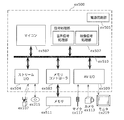
- FIG. 35 is a block diagram showing a configuration example of a television according to Embodiment 12 of the present invention.
- FIG. 36 is a block diagram showing a configuration example of an information reproducing / recording unit according to Embodiment 12 of the present invention.
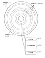
- FIG. 37 shows an example of the structure of a recording medium that is an optical disk according to Embodiment 12 of the present invention.
- FIG. 38 is a configuration diagram illustrating a configuration example of an integrated circuit that realizes the image decoding device according to the thirteenth embodiment of the present invention.
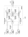
- FIG. 39 is a configuration diagram of an image decoding device according to an aspect of the present invention.
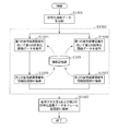
- FIG. 40 is a flowchart illustrating an operation of the image decoding device according to one aspect of the present invention.
- FIG. 40 is a flowchart illustrating an operation of the image decoding device according to one aspect of the present invention.
- FIG. 41 is a block diagram of an integrated circuit according to another aspect of the present invention.
- FIG. 42 is a block diagram of an image decoding apparatus according to another aspect of the present invention.
- FIG. 43 is a block diagram of an image decoding apparatus according to yet another aspect of the present invention.
- FIG. 44 is a configuration diagram of an image encoding device according to an aspect of the present invention.
- FIG. 45 is a flowchart illustrating an operation of the image encoding device according to one aspect of the present invention.
- FIG. 46 is a configuration diagram of a transcoding device according to one embodiment of the present invention.
- FIG. It is a figure which shows the data dependence relationship in H.264 standard.
- FIG. 48A is a configuration diagram illustrating a configuration of a conventional image decoding device.
- FIG. 48B is an explanatory diagram showing the operation of the conventional image decoding device.
- the image decoding apparatus reads an encoded stream generated by encoding an image by a stream division unit, divides the encoded stream so that the two decoding units can decode in parallel, and generates 2 generated by the division.
- One divided stream is stored in each of two buffers.
- Each of the two decoding units reads and decodes the divided stream stored in the buffer.
- each of the two decoding units decodes the divided stream while synchronizing with the other decoding unit by referring to a part of the decoding result by the other decoding unit via the peripheral information memory.
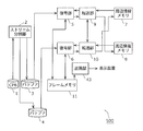
- FIG. 1 is a configuration diagram of an image decoding apparatus according to the present embodiment.
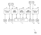
- the image decoding apparatus 100 stores a CPB (Coded Picture Buffer) 1 that buffers an encoded stream, a stream dividing unit 2 that divides the encoded stream, and a divided stream generated by the division.
- Buffers 3 and 4 decoding units 5 and 6 that perform decoding by variable length decoding, inverse frequency conversion, motion compensation, and the like, and a part of the decoding result of neighboring macroblocks, for decoding a decoding target macroblock
- Peripheral information memories 7 and 8 for storing peripheral information to be used, transfer units 9 and 10 for transferring data between the decoding units 5 and 6 and the peripheral information memories 7 and 8, and a decoded divided stream ( A frame memory 11 for storing (decoded images).
- the decoding unit 5, the decoding unit 6, the peripheral information memory 7, the peripheral information memory 8, the transfer unit 9, and the transfer unit 10 are collectively referred to as a parallel decoding unit 60.
- the neighboring macroblocks are macroblocks adjacent to the upper left, upper, upper right, and left of the decoding target macroblock.
- a part of the decoding result of three macroblocks excluding the macroblock adjacent to the left is transferred by the transfer units 9 and 10 as the above-mentioned peripheral information.
- FIG. 2 is a configuration diagram of the decoding unit 5 of the present embodiment.
- the description of the same components as those in FIG. 1 is omitted.
- the transfer unit 9 is divided into two parts for convenience of explanation.
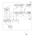
- the decoding unit 5 includes a variable length decoding unit 12 that performs variable length decoding, an inverse quantization unit 13 that performs inverse quantization processing, an inverse frequency conversion unit 14 that performs inverse frequency conversion processing, and data that has been subjected to inverse frequency conversion processing.
- a reconstructing unit 15 that restores an image (reconstructed image) from a (difference image) and a predicted image generated by motion compensation or in-plane prediction, and an in-plane that generates a predicted image from four neighboring macroblocks in a picture
- a prediction unit 16 ; a motion vector calculation unit 17 that calculates a motion vector; a motion compensation unit 18 that generates a prediction image by obtaining a reference image at a position indicated by the motion vector from the frame memory 11 and performing a filtering process; And a deblocking filter unit 19 that performs a deblocking filter process for reducing block noise on the constituent image.
- the configuration of the decoding unit 6 is the same as that of the decoding unit 5.
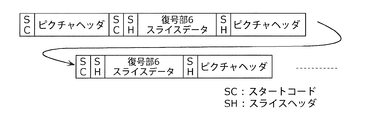
- 3A and 3B are diagrams illustrating the configuration of the encoded stream.
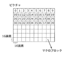
- one picture included in the encoded stream includes a plurality of macroblocks each composed of 16 pixels ⁇ 16 pixels.
- a picture may have a slice made up of one or more macroblocks. Since the H.264 standard does not necessarily have a slice, the slice is not shown in FIG. 3A.
- This macroblock is a processing unit for decoding.
- the numbers in the macroblock in FIG. 3A are macroblock numbers (macroblock addresses) indicating the general coding order of the macroblock.
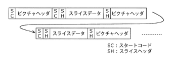
- a start code SC
- a picture header followed by a start code, a slice header (SH), and slice data.
- SPS Sequence Parameter Set
- slice data S-Sequence Parameter Set
- the start code is also called a synchronization word, and is composed of a specific pattern that does not appear in encoded image data such as slice data.
- the first processing operation is an operation in which the stream dividing unit 2 reads the encoded stream from the CPB 1 and divides it into two, and stores the two divided streams generated by the division in the buffers 3 and 4, respectively.
- the second processing operation is an operation in which the divided streams are read from the buffers 3 and 4 and the decoding units 5 and 6 decode them while synchronizing them. These two processing operations can be performed asynchronously.
- the first processing operation that is, the division of the encoded stream will be described.
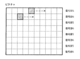
- the stream division unit 2 decodes the encoded stream until at least a macroblock boundary is known, and stores each of a plurality of macroblock lines included in the picture in the buffer 3 or 4 for each picture constituting the encoded stream. .
- the first macroblock line is stored in the buffer 3
- the second macroblock line is stored in the buffer 4
- the third macroblock line is stored in the buffer 3.
- the macro block line is composed of a plurality of macro blocks arranged in a line in the horizontal direction in the picture.
- FIG. 4A, FIG. 4B, and FIG. 4C are diagrams showing macroblock lines to be decoded by the decoding unit 5 and the decoding unit 6, respectively.
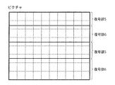
- the stream segmentation unit 2 reads an encoded stream from CPB1, and among the encoded streams, a macroblock line with macroblock addresses 0 to 9 and a macroblock with macroblock addresses 20 to 29
- the macroblock lines are stored in the buffer 3 so that the lines are decoded by the decoding unit 5.
- the stream segmentation unit 2 makes the decoding unit 6 decode the macroblock lines from the macroblock addresses 10 to 19 and the macroblock lines from the macroblock addresses 30 to 39 in the encoded stream. Are stored in the buffer 4.
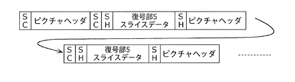
- FIGS. 4B and 4C the picture header and the slice header are duplicated and stored in both the buffers 3 and 4. As a result, as shown in FIG.
- the macroblock line composed of macroblocks having macroblock addresses 0 to 9 and the macroblock line composed of macroblocks having macroblock addresses 10 to 19 are in the same slice. include.
- the slice header of the slice is before the macroblock at the macroblock address 0 and is not before the macroblock at the macroblock address 10.
- a macroblock line consisting of macroblocks having macroblock addresses 10 to 19 has no slice. Does not include a header. Therefore, the stream division unit 2 duplicates the slice header immediately before the macroblock with the macroblock address 0 and inserts it immediately before the macroblock with the macroblock address 10.
- the stream division unit 2 decodes syntax (mb_qp_delta and mb_skip_run) that depends on the order of macroblocks and cannot be divided for each macroblock line, and converts the macroblock lines so that they can be decoded in parallel.
- mb_qp_delta is obtained by encoding a difference in qp value (quantization parameter) between macroblocks.
- the stream dividing unit 2 converts mb_qp_delta for the first macroblock of the macroblock line into the qp value itself instead of the difference, and stores it in the buffer 3 and the buffer 4.
- the stream segmentation unit 2 uses H.264 for mb_qp_delta for macroblocks other than the head.
- mb_skip_run is a syntax indicating how many skip macroblocks continue.
- the stream dividing unit 2 converts this mb_skip_run into a value indicating how many skipped macroblocks continue in units of macroblock lines.
- in-plane prediction for a decoding target macroblock MBx requires reconstructed images of neighboring macroblocks MBa to MBd located at the upper left, upper, upper right, and left of the decoding target macroblock MBx.
- the motion vectors of the neighboring macroblocks MBa to MBc located on the upper, upper right and left of the decoding target macroblock MBx are required.
- the result of the deblocking filter process is necessary for the neighboring macroblocks MBb and MBa located above and to the left of the decoding target macroblock MBx. In this way, H.C.
- the image decoding apparatus 100 decodes two divided streams in parallel while maintaining the above-described data dependency by shifting the horizontal position of two decoding target macroblocks to be decoded in parallel.
- the upper neighboring macroblock is at least one macroblock among neighboring macroblocks adjacent to the decoding target macroblock on the upper left, upper, and upper right.
- 5A and 5B are diagrams showing the positions of two decoding target macroblocks decoded in parallel.
- the decoding target macroblock decoded by the decoding unit 5 may be at least two macroblocks ahead in the horizontal direction compared to the decoding target macroblock decoded by the decoding unit 6.
- the decoding unit 5 and the decoding unit 6 can perform decoding simultaneously in parallel. That is, when each of the decoding units 5 and 6 decodes two adjacent macroblock lines in the upper and lower directions, the decoding unit 6 starts from the decoding target macroblock decoded by the decoding unit 5 by at least two macroblocks in the horizontal direction.
- the macroblock on the left is decoded as a decoding target macroblock.
- the position of the decoding target macroblock decoded by the decoding unit 5 and the decoding unit 6 only needs to be shifted by at least 2 macroblocks in the horizontal direction, and is shifted more than 2 macroblocks as shown in FIG. 5B. It doesn't matter.
- FIG. 6 is a flowchart showing the decoding of the slice by the decoding unit 5 of the image decoding apparatus 100.
- the decoding unit 5 decodes the macroblock lines with macroblock addresses 0 to 9, the macroblock lines with macroblock addresses 20 to 29, and the macroblock lines with macroblock addresses 40 to 49.
- the decoding unit 6 decodes the macroblock lines with the macroblock addresses 10 to 19, the macroblock lines with the macroblock addresses 30 to 39, and the macroblock lines with the macroblock addresses 50 to 59.
- the variable length decoding unit 12 of the decoding unit 5 reads partial data of the divided stream from the buffer 3 (S100).
- the variable length decoding unit 12 searches for the start code for the read data (S101). That is, the variable length decoding unit 12 determines whether or not the read data has a start code. If the start code is not found (No in S101), the variable length decoding unit 12 further reads the next data from the buffer 3 until the start code is found (S100). If the start code is found (Yes in S101), the variable length decoding unit 12 decodes the header (S102). Based on the header decoding result, the variable length decoding unit 12 determines whether the data following the header is slice data (S103).
- variable length decoding unit 12 reads the next data from the buffer 3 again (S101).
- the decoding unit 5 performs a decoding process of the macroblock included in the slice data (slice) (S104). Details of the decoding process of the macroblock will be described later.
- the variable length decoding unit 12 determines whether or not decoding of all the macroblocks in the slice is completed (S105). If it is determined that the processing has not been completed (No in S105), the decoding unit 5 performs the macroblock decoding process again (S104). On the other hand, when it is determined that the decoding of all the macroblocks in the slice is completed (Yes in S105), the decoding unit 5 ends the decoding for the slice.
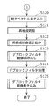
- FIG. 7 and 8 are flowcharts showing a macroblock decoding process.
- the variable length decoding unit 12 performs variable length decoding on the macroblock data read from the buffer 3 (S110).
- the inverse quantization unit 13 inversely quantizes the coefficient data obtained as a result of the variable length decoding (S111).
- the inverse frequency transform unit 14 performs inverse frequency transform on the inversely quantized coefficient data (S112).
- the motion vector calculation unit 17 uses the transfer unit 9 from the peripheral information memory 7 as the peripheral information to calculate the motion vector of the decoding target macroblock later. Read (S113). Details of the motion vector reading process (S113) will be described later.
- the intra prediction unit 16 uses the transfer unit 9 from the peripheral information memory 7 as peripheral information for a part of the reconstructed image of the upper peripheral macro block to perform intra prediction of the decoding target macro block later. And read (S114). Details of the reconstructed image reading process (S114) will be described later.
- the decoding unit 5 determines whether or not the decoding target macroblock is an inter MB (macroblock decoded by inter-screen prediction) (S115). If it is determined to be an inter MB (Yes in S115), the motion vector calculation unit 17 uses the motion vector of the upper neighboring macroblock read in step S113 to obtain the motion vector of the decoding target macroblock. Calculate (S116).
- the motion compensation unit 18 reads a reference image from the frame memory 11 using the motion vector calculated in step S116, and generates a predicted image by performing motion compensation based on the reference image (S117).
- step S115 when it is determined in step S115 that the decoding target macroblock is not an inter MB (No in S115), that is, when the decoding target macroblock is an intra MB (macroblock decoded by intra prediction).
- the in-plane prediction unit 16 performs in-plane prediction on the decoding target macroblock using the reconstructed image of the upper neighboring macroblock read in step S114 (S118).
- the motion vector calculation unit 17 writes the motion vector of the decoding target macroblock calculated in step S116 into the peripheral information memory 8 through the transfer unit 9 as peripheral information (S120).
- the motion vector written as the peripheral information may be all the calculated motion vectors, or may be only the motion vector used for calculating the motion vector of the lower macroblock. That is, in step S120, the motion vector calculation unit 17 does not always write the motion vector calculated in step S116 to the peripheral information memory 8, and the motion vector is used to calculate the motion vector of the lower macroblock. Only in this case, the motion vector calculated in step S116 may be written in the peripheral information memory 8.
- the motion vector writing process (S120) to the peripheral information memory will be described later.
- the reconstruction unit 15 adds the prediction image generated by the motion compensation (S117) or the in-plane prediction (S118) and the difference image generated by the inverse frequency transform in step S112, thereby reconstructing the reconstruction image.
- An image is generated (S121). Processing for generating a reconstructed image in this way is hereinafter referred to as reconstruction processing.
- the reconstruction unit 15 writes a part of the reconstructed image generated in step S121 into the peripheral information memory 8 through the transfer unit 9 as peripheral information (S122).
- the reconstructed image to be written may be all of the reconstructed image, or may be only a portion used for in-plane prediction of the lower macroblock.
- the reconstructed image writing process (S122) will be described later.
- the deblocking filter unit 19 uses the transfer unit 9 from the peripheral information memory 7 to transfer a partial image (deblocking filter image) of the peripheral macroblocks on which the deblocking filter processing has been performed to the peripheral information. (S123). The process of reading the deblock filter image will be described later.
- the deblocking filter unit 19 performs deblocking filter processing of the decoding target macroblock using the deblocking filter image, and writes the processing result (decoded image) in the frame memory 11 (S124).
- the deblocking filter unit 19 is an image (described later, which is used in the deblocking filtering process of the lower macroblock among the decoding target macroblock subjected to the deblocking filtering process and the neighboring macroblock on the left side thereof.
- the write target deblock filter image is written as peripheral information into the peripheral information memory 8 via the transfer unit 9 (S125).
- FIG. 9 is an explanatory diagram for explaining the motion vector calculation method in step S116 of FIG.
- the motion vector calculation unit 17 calculates the motion vectors mvB, MBb and MBc of the neighboring macroblocks MBb and MBc above and to the upper right of the decoding target macroblock MBx. mvC and the motion vector mvA already calculated for the neighboring macroblock MBa on the left of the decoding target macroblock MBx are used.
- the motion vector calculation unit 17 reads the motion vectors mvB and mvC of the upper peripheral macro blocks MBb and MBc from the peripheral information memory 7 via the transfer unit 9 in advance (in step S113 in FIG. 7).
- the motion vectors mvB and mvC can be used.
- the motion vector calculation unit 17 calculates the predicted motion vector mvp of the motion vector mv of the decoding target macroblock MBx by obtaining the median of the motion vectors mvA, mvB, and mvC. Then, the motion vector calculation unit 17 calculates the motion vector mv of the decoding target macroblock MBx by adding the difference motion vector mvd to the predicted motion vector mvp. Note that the differential motion vector mvd is included in a divided stream (encoded stream) in a state of variable length encoding. Therefore, the motion vector calculation unit 17 acquires the differential motion vector mvd subjected to variable length decoding from the variable length decoding unit 12, and calculates the above-described motion vector mv using the differential motion vector mvd.
- FIG. 10 is an explanatory diagram for explaining the in-plane prediction in step S118 of FIG.
- the in-plane prediction unit 16 uses the reconstructed images of the surrounding macroblocks MBa to MBd at the upper left, upper, upper right, and left of the decoding target macroblock MBx according to the in-plane prediction mode, and performs decoding. In-plane prediction is performed on the target macroblock MBx. Specifically, the in-plane prediction unit 16 performs a reconstructed partial image including 1 ⁇ 16 pixels at the right end of the reconstructed image of the peripheral macroblock MBa and a lower right of the reconstructed image of the peripheral macroblock MBd.
- the in-plane prediction unit 16 reads the reconstructed partial images of the upper peripheral macroblocks MBc to MBd from the peripheral information memory 7 via the transfer unit 9 in advance (in step S114 of FIG. 7). These reconstructed partial images can be used.
- the in-plane prediction mode is included in the divided stream (encoded stream) in a state of variable length encoding. Therefore, the in-plane prediction unit 16 acquires the in-plane prediction mode that has been variable-length decoded from the variable-length decoding unit 12, and performs the above-described in-plane prediction according to the in-plane prediction mode.
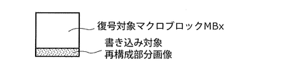
- FIG. 11 is an explanatory diagram for explaining the writing of the reconstructed image in step S122 of FIG.
- the reconstruction unit 15 uses, as the write target reconstruction partial image, an image composed of the lower 16 ⁇ 1 pixels among the reconstruction images of the decoding target macroblock MBx as illustrated in FIG. Write to the peripheral information memory 8 via the transfer unit 9. That is, the writing target reconstructed partial image including 16 ⁇ 1 pixels is used as a reconstructed partial image, for example, for intra prediction by the decoding unit 6 of another macroblock below the decoding target macroblock MBx.
- 12A to 12C are explanatory diagrams for explaining the deblocking filter processing in step S124 of FIG.
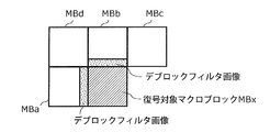
- the deblocking filter processing is performed using a total of 6 pixels, 3 pixels on both sides of the boundary of the sub-block consisting of 4 ⁇ 4 pixels. Therefore, as shown in FIG. 12A, in the deblocking filter processing of the decoding target macroblock MBx, the deblocking filter image of the neighboring macroblock MBb above the decoding target macroblock MBx and the left of the decoding target macroblock MBx A deblock filter image of a certain peripheral macroblock MBa is required.
- the deblock filter image of the peripheral macroblock MBb is composed of the lower 16 ⁇ 3 pixels of the peripheral macroblock MBb subjected to the deblock filter processing, and the deblock filter image of the peripheral macroblock MBa is subjected to the deblock filter processing. It consists of 3 ⁇ 16 pixels on the right side of the neighboring macroblock MBa.
- the deblocking filter unit 19 transmits the peripheral macroblock MBb from the peripheral information memory 7 via the transfer unit 9 in advance.
- the deblock filter image is read out.
- the deblock filter unit 19 performs a deblock filter process on the decoding target macroblock MBx using the read deblock filter image. Since the deblocking filter unit 19 performs the deblocking filter process on the surrounding macroblock MBa itself, when performing the deblocking filter process on the decoding target macroblock MBx, the deblocking filter unit 19 A deblock filter image is already held.
- an image composed of pixels on the right and bottom of the decoding target macroblock MBx is processed as a decoded image by performing deblocking filter processing on the macroblocks on the right and bottom of the decoding target macroblock MBx. Confirmed.
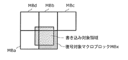
- the deblocking filter unit 19 When the deblocking filter unit 19 writes the decoded image shown in FIG. 12B to the frame memory 11, as shown in FIG. 12C, the deblocking filter unit 19 is shifted by 3 pixels to the upper left from the decoding target macroblock MBx in order to avoid a decrease in transfer efficiency. Write the decoded image of the writing target area at the position. In other words, since the overall shape of the three decoded images shown in FIG. 12B is not rectangular, when these decoded images are written to the frame memory 11, compared to writing an image of a rectangular area. Transfer efficiency is low. Therefore, the deblocking filter unit 19 writes the decoded image of the rectangular writing target area composed of 16 ⁇ 16 pixels in the frame memory 11.
- FIG. 13 is an explanatory diagram for describing writing of the write target deblock filter image in step S125 of FIG.
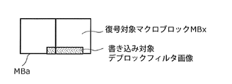
- step S125 of FIG. 8 the deblock filter unit 19 transfers the write target deblock filter image including a part of the image subjected to the deblock filter processing of the decoding target macroblock MBx, as shown in FIG. Write to the peripheral information memory 8 via the unit 9.
- This writing target deblock filter image is an image composed of 13 ⁇ 3 pixels at the lower left of the decoding target macroblock MBx that has been subjected to the deblocking filter processing, and the deblocking filter processing of the macroblock MBa that is to the left of the decoding target macroblock MBx. And an image composed of 3 ⁇ 3 pixels at the lower right of the obtained images.
- the decoding unit 5 decodes the divided stream of the buffer 3 using the peripheral information stored in the peripheral information memory 7, and converts a part of the information generated by the decoding to the peripheral information. Is stored in the peripheral information memory 8.
- the decoding unit 5 performs image processing on the peripheral information in the peripheral information memory 7 and the decoding target macroblock. Then, at least a part of each of the decoding target macroblock and the peripheral information subjected to the image processing is stored in the frame memory 11.
- the peripheral information of the peripheral information memory 7 described above is at least part of other macroblocks decoded by the decoding unit 6 belonging to another macroblock line adjacent to the macroblock line to which the macroblock to be decoded belongs. is there.
- the decoding unit 6 decodes the divided stream of the buffer 4 using the peripheral information stored in the peripheral information memory 8, and stores a part of the information generated by the decoding in the peripheral information memory 7 as peripheral information. To do.
- the decoding unit 6 performs image processing on the peripheral information in the peripheral information memory 8 and the decoding target macroblock. Then, at least a part of each of the decoding target macroblock and the peripheral information subjected to the image processing is stored in the frame memory 11.
- the peripheral information in the peripheral information memory 8 described above is at least part of other macroblocks decoded by the decoding unit 5 belonging to another macroblock line adjacent to the macroblock line to which the macroblock to be decoded belongs. is there.
- the overall decoding speed can be sufficiently increased, As a result, it is possible to improve decoding performance or decoding efficiency.
- the deblocking filter process has already been performed on the macroblock. Therefore, it is not necessary to read the macroblock from the frame memory 11 in order to perform the deblocking filter process after the macroblock is stored in the frame memory 11. As a result, the frequency of access to the frame memory 11 can be reduced.
- FIG. 14 is a flowchart showing the reading processing of the peripheral information from the peripheral information memory 7 by the decoding unit 5 and the transfer unit 9.
- the peripheral information is a motion vector, a reconstructed partial image, or a deblock filter image.
- the decoding unit 6 writes the peripheral information used for decoding the macroblock by the decoding unit 5 in the peripheral information memory 7 via the transfer unit 10.
- the transfer unit 9 acquires from the transfer unit 10 the value of the write pointer in the peripheral information memory 7 when this writing is performed.
- the value of the write pointer indicates an address in the peripheral information memory 7 where writing is performed next.
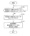
- the transfer unit 9 compares the value of the write pointer with the value of the read pointer for reading the peripheral information from the peripheral information memory 7 (S130).
- the value of this read pointer indicates the address in the peripheral information memory 7 to be read next.
- the transfer unit 9 increments the value of the read pointer (S131), and the peripheral information at the address indicated by the read pointer is peripheral.
- the information is read from the information memory 7 and transferred to the decoding unit 5 (S133).
- the transfer unit 9 waits.
- the transfer unit 9 increments the value of the read pointer and performs transfer. If the two values are equal, the peripheral information to be read is not yet written in the peripheral information memory 7. Judge and wait until the peripheral information is written.
- peripheral information memory in each of the motion vector writing process (S120), the writing target reconstructed partial image writing process (S122), and the writing target deblock filter image writing process (S125) described later.
- a method of writing peripheral information to 8 will be described.
- the operation is the same except that the type of peripheral information to be written is different. Therefore, the above-described processes will be described together using the flowchart shown in FIG.
- FIG. 15 is a flowchart showing processing for writing peripheral information to the peripheral information memory 8 by the decoding unit 5 and the transfer unit 9.
- the peripheral information is a motion vector, a writing target reconstructed partial image, or a writing target deblock filter image.
- the decoding unit 6 reads the peripheral information for decoding the decoding target macroblock from the peripheral information memory 8 via the transfer unit 10.
- the transfer unit 9 acquires the value of the read pointer of the peripheral information memory 8 when this reading is performed from the transfer unit 10.
- the value of the read pointer indicates an address at which the next read in the peripheral information memory 8 is performed.
- the transfer unit 9 compares the value of the read pointer with the value of the write pointer for writing the peripheral information used for decoding the macroblock by the decoding unit 6 into the peripheral information memory 8 (S140).
- the value of the write pointer indicates an address in the peripheral information memory 8 where writing is performed next.
- the transfer unit 9 waits.
- the transfer unit 9 increments the write pointer (S141) and decrypts.
- the peripheral information generated by the unit 5 is acquired and written in the peripheral information memory 8 (S142).
- the write pointer catches up or overtakes the read pointer.
- new peripheral information may be overwritten on peripheral information that has not yet been read from the peripheral information memory 8, and the peripheral information that has not been read may be erased.
- the write pointer catches up with the read pointer even if the peripheral information is written to the peripheral information memory 8 next time, or There is no possibility of overtaking.
- the transfer unit 9 increments the value of the write pointer and writes the peripheral information.
- the transfer unit 9 performs the process of the decoding unit 6, that is, the peripheral information by the transfer unit 10. It is determined that the reading of the peripheral information from the memory 8 is delayed, and the process waits until the reading is performed and the value of the reading pointer increases.
- the above is the description of the decoding process by the decoding unit 5.
- the decoding process by the decoding unit 6 is the same as the decoding process by the decoding unit 5 except that the transfer unit 10 is used and the peripheral information is written in the peripheral information memory 7 and read from the peripheral information memory 8. Therefore, the description of the decoding process by the decoding unit 6 is omitted.
- FIG. 16 is a diagram showing a range of decoded images written in the frame memory 11 by the decoding unit 5 and the decoding unit 6.
- the decoding target image included in the picture is assigned to each of the decoding unit 5 and the decoding unit 6 in units of macroblock lines.
- the decoded image (image subjected to the deblocking filter process) written to the frame memory 11 by each of the decoding unit 5 and the decoding unit 6 deviates from the assigned macroblock line as shown in FIG. 12C. Therefore, as shown in FIG. 16, a decoded image of a region (region surrounded by a horizontal solid line in FIG. 16) deviated from the macroblock line (region surrounded by a horizontal dotted line in FIG. 16) is obtained.
- Each of the decoding unit 5 and the decoding unit 6 writes in the frame memory 11.
- the encoded stream is H.264.
- This is an operation in the case of a frame structure or a field structure in the H.264 standard.
- an encoded stream called an MBAFF (Macro Block Adaptive Frame Field) structure.
- the frame structure or the field structure is referred to as a non-MBAFF structure.
- the encoding order is different between the MBAFF structure and the non-MBAFF structure.
- FIG. 17 is a diagram illustrating macroblock lines to be decoded by the decoding unit 5 and the decoding unit 6 when the encoded stream has an MBAFF structure.
- a macroblock pair in which two upper and lower macroblocks are grouped together is sequentially encoded, not in the raster order as in the non-MBAFF structure. That is, in one macroblock pair, the lower macroblock is encoded after the upper macroblock is encoded.
- the macroblock pair on the right side of the macroblock pair is encoded in the same manner as described above.
- the stream dividing unit 2 sends the macro block pair line to the buffer 3 or the buffer 4 for every two adjacent macro block lines (macro block pair lines) constituting the picture. By allocating, the picture (encoded stream) is divided. Then, as illustrated in FIG.
- the decoding unit 5 and the decoding unit 6 decode the macroblock pair lines, respectively, so that the image decoding apparatus 100 can perform the encoding of the MBAFF structure as in the case where the encoded stream has the non-MBAFF structure. Stream can be decoded.
- FIG. 18 is a diagram illustrating a range of a decoded image written in the frame memory 11 when the encoded stream has an MBAFF structure.
- each of the decoding unit 5 and the decoding unit 6 has an area (horizontal direction in FIG. 18) shifted from a macroblock pair line (two areas surrounded by a horizontal dotted line in FIG. 18).
- the decoded image in the area surrounded by the solid line is written into the frame memory 11.
- the stream dividing unit 2 divides the encoded stream, and the decoding unit 5 and the decoding unit 6 operate in parallel using the peripheral information memory 7 and the peripheral information memory 8 in parallel. Therefore, the original encoded stream is not necessarily divided into units such as slices. H.264 standard encoded streams can be decoded in parallel. Furthermore, in the present embodiment, the processing performance can be doubled as compared with the case where the encoded stream is decoded by only one decoding unit. Further, when realizing the same performance, the operating frequency of each decoding unit can be halved, and the power consumption can be reduced.
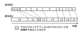
- FIG. 19A and FIG. 19B are diagrams illustrating timings at which a macroblock is processed when the encoded stream has a non-MBAFF structure.
- the decoding unit 5 and the decoding unit 6 operate in parallel in synchronization using the peripheral information memory 7 and the peripheral information memory 8 as buffers, so that as shown in FIG. 19A, the decoding unit 5 And the decoding unit 6 can start processing simultaneously. Furthermore, it becomes easy to control the start of decoding. Further, in the decoding unit 6, if the peripheral information necessary for the processing is written in the peripheral information memory 8 by the decoding unit 5, the decoding target macroblock can be processed.
- FIG. 19B in the image decoding apparatus of Patent Document 1, two decoding units 1300a and 1300b each decode one macroblock within a predetermined period. That is, the decoding units 1300a and 1300b operate in synchronization with the macroblock unit. In such a case, of the two decoding units 1300a and 1300b, the one that finishes decoding the macroblock earlier waits for the start of the decoding process for the next macroblock.
- the encoded stream is divided into two divided streams, and the two divided streams are decoded in parallel by the decoding units 5 and 6, respectively. It is possible to omit the macroblock pipeline control unit as in Patent Document 1 that controls the timing of the above. Furthermore, even when the image decoding apparatus 100 includes a large number of decoding units for dividing an encoded stream into three or more divided streams and decoding the divided streams in parallel, as described in Patent Document 1 above. It is not necessary to lay a signal line between the macro block line control unit and the decoding unit, and the image decoding apparatus 100 can be easily realized. Furthermore, in the image decoding apparatus 100 according to the present embodiment, the H.264 / H.
- Peripheral information required due to data dependency in the H.264 standard is transmitted and received between the decoding units 5 and 6 via the peripheral information memories 7 and 8. Therefore, if the peripheral information required for decoding is stored in the peripheral information memory, each of the decoding units 5 and 6 uses the stored peripheral information without waiting for decoding by the other decoding unit. The decoding of the divided stream can be continued. As a result, it is possible to prevent decoding from being interrupted and causing time loss as in the image decoding device of Patent Document 1, and to improve decoding efficiency.
- the image decoding apparatus 100 is the H.264 standard. Although decoding is performed according to the H.264 standard, decoding may be performed according to other image coding standards such as VC-1.
- the present embodiment may be realized as a hardware circuit or software executed on a processor, or partly realized as a hardware circuit and partly executed on a processor. It may be realized as software.
- the image decoding apparatus 100 includes two decoding units, but is not limited to two, and may include three, four, or a larger number of decoding units.
- the stream dividing unit 2 generates the same number of divided streams as the number of decoding units provided by dividing the encoded stream.
- the image decoding apparatus 100 is an H.264 standard.
- the left, upper, upper right, and upper left four neighboring macroblocks are referred to.
- only the left neighboring macroblock or only the left and upper neighboring macroblocks may be referred to.
- the peripheral macroblock to be referred to may be changed depending on the processing.
- the constituent element for storing the peripheral information is the peripheral information memory, but the constituent element may be any recording medium such as a flip-flop or another storage element. .
- peripheral information used for motion vector calculation, in-plane prediction, and deblocking filter processing is stored in one peripheral information memory.
- the deblocking filter process is performed using the three pixels on both sides of the boundary, and the decoded image of the writing target area at the position shifted by the number of pixels is written in the frame memory 11.
- the number of pixels may be larger than 3 pixels.
- the motion vector, the reconstructed partial image, and the deblock filter image are stored as the peripheral information in the peripheral information memory.
- the present invention is not limited to this, and is necessary between macroblocks. Any information may be stored as long as the information becomes.
- the intra prediction mode, the total number of non-zero coefficients (TotalCoeff) of the frequency coefficients of the macroblock, or the reference picture number (ref_idx) indicating the reference picture may be used as the peripheral information.
- the image decoding apparatus 100 includes one transfer unit and one peripheral information memory for each decoding unit, it is not necessarily required for each decoding unit. For example, as long as the transfer performance is satisfied, one transfer unit shared with a plurality of decoding units and a peripheral information memory may be provided.
- the stream dividing unit 2 simply divides the encoded stream.
- the stream dividing unit 2 does not simply divide, but also decodes all or a part of the divided stream, or changes the encoding method of the divided stream.
- the divided stream obtained by converting the encoding method may be stored in the buffer.
- the decoding unit of the present embodiment stores only the decoded image in the frame memory 11, but control data associated with the decoded image, for example, H.264, etc. Information necessary for decoding in the H.264 standard direct mode may also be stored.
- Embodiment 2 (2-1. Overview) First, an outline of the image decoding apparatus according to Embodiment 2 of the present invention will be described.
- the image decoding apparatus divides the encoded stream into four parts, and the four divided streams generated by the division are decoded in parallel by the four decoding units.
- Each of the four decoding units reads and decodes the divided stream stored in the buffer.
- each of the four decoding units decodes the divided stream while synchronizing with the other decoding units by referring to a part of the decoding result by the other decoding units via the peripheral information memory.
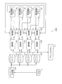
- FIG. 20 is a configuration diagram of the image decoding apparatus according to the present embodiment.
- the same constituent elements as those in the first embodiment are denoted by the same reference numerals, and description thereof is omitted.
- the image decoding apparatus 200 stores the CPB 1, the frame memory 11, the stream dividing unit 20 that divides the encoded stream into four, and each of the four divided streams generated by the division.
- the encoded stream stored in CPB1 is read by the stream dividing unit 20, and divided into four as shown in FIG. 21, and the four divided streams generated by the division are the buffer 21, the buffer 22, and the buffer, respectively. 23, stored in the buffer 24.
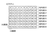
- FIG. 21 is an explanatory diagram for explaining division of the encoded stream.
- the stream dividing unit 20 divides the encoded stream for each macroblock line so that the macroblock line is allocated to one of the four decoding units 25, 26, 27, and 28. For example, macroblock lines with macroblock addresses 0 to 9 and macroblock lines with macroblock addresses 40 to 49 are allocated to the decoding unit 25. Similarly, macroblock lines with macroblock addresses 10 to 19 and macroblock lines with macroblock addresses 50 to 59 are allocated to the decoding unit 26. Similarly, macroblock lines with macroblock addresses 20 to 29 and macroblock lines with macroblock addresses 60 to 69 are allocated to the decoding unit 27.
- the stream dividing unit 20 generates the first to fourth divided streams by dividing the encoded stream.
- the first divided stream includes macroblock lines with macroblock addresses 0 to 9 and macroblock lines with macroblock addresses 40 to 49.
- the second divided stream includes macroblock lines with macroblock addresses 10 to 19 and macroblock lines with macroblock addresses 50 to 59.
- the third divided stream includes macroblock lines with macroblock addresses 20 to 29 and macroblock lines with macroblock addresses 60 to 69.
- the fourth divided stream includes macroblock lines with macroblock addresses 30 to 39 and macroblock lines with macroblock addresses 70 to 79.
- the stream dividing unit 20 stores the first divided stream in the buffer 21, stores the second divided stream in the buffer 22, stores the third divided stream in the buffer 23, and stores the fourth divided stream in the buffer 24. To store.
- the decoding unit 25 reads the first divided stream from the buffer 21 and decodes it.
- the operation of the decoding unit 25 is the same as the operation of the decoding unit 5 shown in the first embodiment.
- the transfer unit 33 is used to read the peripheral information that is the decoding result of the decoding unit 28 from the peripheral information memory 29 and The difference is that the peripheral information as the decoding result is written in the peripheral information memory 30.
- the decoding unit 25 writes the decoded image into the frame memory 11.
- the decoding unit 26 reads the second divided stream from the buffer 22 and decodes it.
- the operation of the decoding unit 26 is the same as the operation of the decoding unit 5 described in the first embodiment.
- the transfer unit 34 is used to read the peripheral information that is the decoding result of the decoding unit 25 from the peripheral information memory 30 and The difference is that the peripheral information as the decoding result is written in the peripheral information memory 31.
- the decoding unit 26 writes the decoded image into the frame memory 11.
- the decoding unit 27 reads the third divided stream from the buffer 23 and decodes it.
- the operation of the decoding unit 27 is the same as the operation of the decoding unit 5 described in the first embodiment, but the transfer unit 35 is used to read the peripheral information that is the decoding result of the decoding unit 26 from the peripheral information memory 31 and The difference is that the peripheral information as the decoding result is written in the peripheral information memory 32.
- the decoding unit 27 writes the decoded image in the frame memory 11.
- the decoding unit 28 reads the fourth divided stream from the buffer 24 and decodes it.
- the operation of the decoding unit 28 is the same as the operation of the decoding unit 5 shown in the first embodiment, but the transfer unit 36 is used to read the peripheral information that is the decoding result of the decoding unit 27 from the peripheral information memory 32 and The difference is that the peripheral information as the decoding result is written in the peripheral information memory 29. Note that the decoding unit 28 writes the decoded image into the frame memory 11.
- the image decoding apparatus 200 divides the encoded stream into four by the stream dividing unit 20, and the operations of the respective decoding units operate in the same manner as in the first embodiment.
- the stream division unit 20 divides the encoded stream into four, and the four decoding units decode the four divided streams in parallel. Therefore, in the image decoding apparatus 200 according to the present embodiment, the processing performance is doubled when operating at the same operating frequency as the image decoding apparatus 100 as compared with the image decoding apparatus 100 according to the first embodiment. be able to. Further, when realizing the same performance, the operating frequency of each decoding unit can be halved, and the power consumption can be reduced.
- each of the decoding units 25, 26, 27, and 28 does not need to be synchronized with the other three decoding units, and may be synchronized with one adjacent decoding unit. Wiring between components is easy to draw, and an image decoding device that improves decoding efficiency can be easily realized.
- the image decoding apparatus 200 includes four decoding units, but is not limited to four, and may include eight, sixteen, or a larger number of decoding units.
- Embodiment 3 (3-1. Overview) First, an outline of the image decoding apparatus according to Embodiment 3 of the present invention will be described.
- the image decoding apparatus includes a switch for switching data input to each of the decoding unit and the peripheral information memory. By switching by these switches, the image decoding apparatus according to the present embodiment synchronizes the two decoding units and decodes one encoded stream, and operates the two decoding units independently to generate two codes. Switching to the process of decoding the stream.
- FIG. 22 is a configuration diagram of the image decoding apparatus according to the present embodiment. Note that the same components as those in Embodiment 1 are denoted by the same reference numerals, and description thereof is omitted.
- the image decoding apparatus 300 includes each component of the image decoding apparatus 100 according to the first embodiment, and also includes a CPB 37 that stores an encoded stream, and a switch 38 that switches data input to the decoding unit 5.
- Switch 38, switch 39, switch 40, and switch 41 all simultaneously select “0” or “1” inputs.
- the switch 38 switches the data input to the decoding unit 5 to the divided stream stored in the buffer 3 when the input “0” is selected, and inputs the data to the decoding unit 5 when the input “1” is selected. Is switched to the encoded stream stored in the CPB 37.
- the switch 39 switches the data input to the decoding unit 6 to the divided stream stored in the buffer 4 when “0” input is selected, and inputs to the decoding unit 6 when “1” input is selected. Is switched to the encoded stream stored in CPB1.
- the switch 40 switches the data input (stored) in the peripheral information memory 7 to the peripheral information transferred from the decoding unit 6 via the transfer unit 10, and inputs “1”. Is selected, the data input to the peripheral information memory 7 is switched to the peripheral information transferred from the decoding unit 5 via the transfer unit 9.
- the switch 41 switches the data input (stored) in the peripheral information memory 8 to the peripheral information transferred from the decoding unit 5 via the transfer unit 9, and inputs “1”. Is selected, the data input to the peripheral information memory 8 is switched to the peripheral information transferred from the decoding unit 6 via the transfer unit 10.
- image decoding apparatus 300 decodes the encoded stream stored in CPB1, as in the first embodiment. To do. That is, the stream dividing unit 2 of the image decoding apparatus 300 reads and divides the encoded stream from the CPB 1, writes the two divided streams generated by the division into the buffer 3 and the buffer 4, respectively, and the decoding unit 5 and the decoding unit 6 respectively. Decodes these split streams in parallel. Since the operation of the image decoding apparatus 300 in this case is exactly the same as that of the first embodiment, description thereof is omitted.
- the image decoding device 300 When the switch 38, the switch 39, the switch 40, and the switch 41 all select “1” input, the image decoding device 300 performs an operation different from that of the first embodiment. That is, the decoding unit 5 and the decoding unit 6 of the image decoding apparatus 300 respectively read different encoded streams stored in different CPBs 37 and 1 and decode them independently. The decoding unit 5 reads and decodes the CPB 37 encoded stream. The operation of the decoding unit 5 at this time is that the peripheral information is written in the peripheral information memory 7 via the transfer unit 9 and that the decoding by the transfer unit 9 and the transfer unit 10 is not performed in synchronization with the decoding unit 6. The same as in the first embodiment.
- the decoding unit 5 writes the peripheral information that is the decoding result by itself into the peripheral information memory 7 by using the transfer unit 9, reads the peripheral information that has been written by itself by using the transfer unit 9, The decoding target macroblock is decoded using the peripheral information. Since the operation of the decoding unit 6 is the same as that of the decoding unit 5, a description thereof will be omitted.
- the image decoding apparatus 300 includes two decoding units, but may include four or a larger number of decoding units.
- switches 38 to 41 in the present embodiment are not necessarily physical or circuit switches, and may be switches that switch data by switching memory addresses, for example.
- the image decoding apparatus includes a switch for switching the encoded stream input to the stream dividing unit. By switching by this switch, the image decoding apparatus according to the present embodiment divides one encoded stream, and decodes the two divided streams in synchronization by two decoding units, and two encoded streams. Are switched to time-division parallel decoding processing in which the parallel decoding processing for each of the above is divided in time.
- FIG. 23 is a configuration diagram of the image decoding apparatus according to the present embodiment.
- the same components as those in the first embodiment are denoted by the same reference numerals, and description thereof is omitted.
- the image decoding apparatus 400 includes each component of the image decoding apparatus 100 according to the first embodiment, and switches between the CPB 37 that stores the encoded stream and the encoded stream input to the stream dividing unit 2. And a switch 42.
- the switch 42 selects the input “0”, the switch 42 switches the encoded stream input to the stream dividing unit 2 to the encoded stream stored in the CPB 1.
- the switch 42 selects the input “1”, the stream dividing unit The encoded stream input to 2 is switched to the encoded stream stored in the CPB 37.
- the image decoding apparatus 400 performs the parallel decoding process described above, and the switch 42 repeatedly selects “0” input and “1” input alternately. If so, the above time-division parallel decoding process is performed.
- the image decoding apparatus 400 decodes the encoded stream stored in the CPB 1 as in the first embodiment. That is, the stream division unit 2 of the image decoding apparatus 400 reads and divides the encoded stream from the CPB 1, writes the two divided streams generated by the division into the buffer 3 and the buffer 4, and decodes the decoding unit 5 and the decoding unit 6. Decodes these split streams in parallel. Since the operation of the image decoding apparatus 400 in this case is exactly the same as that of the first embodiment, description thereof is omitted.
- the stream dividing unit 2 of the image decoding apparatus 400 has two different ones stored in different CPBs.
- the division processing for the encoded stream is performed by switching over time. That is, when the switch 42 selects “0” input, the stream dividing unit 2 reads and divides the encoded stream stored in the CPB 1 and generates 2 generated by dividing the encoded stream.
- the decoding unit 5 and the decoding unit 6 decode one divided stream in synchronization. Since the operation of the image decoding apparatus 400 at this time is the same as that of Embodiment 1, the description thereof is omitted.
- the stream dividing unit 2 reads and divides the encoded stream stored in the CPB 37 and generates 2 generated by dividing the encoded stream.
- the decoding unit 5 and the decoding unit 6 decode one divided stream in synchronization. Since the operation of the image decoding apparatus 400 at this time is the same as that of Embodiment 1 except that the encoded stream is read from the CPB 37, description thereof is omitted.
- FIG. 24 is an explanatory diagram for explaining time-division parallel decoding processing.
- the switch 42 first selects an input of “0”. As a result, the image decoding apparatus 400 performs parallel decoding processing on picture 0 of the encoded stream stored in CPB1. When the parallel decoding process for the picture 0 is completed, the switch 42 selects an input of “1”. As a result, the image decoding apparatus 400 performs parallel decoding processing on picture 0 of the encoded stream stored in the CPB 37. When the parallel decoding process for the picture 0 is completed, the switch 42 selects the input of “0” again. As a result, the image decoding apparatus 400 performs parallel decoding processing on picture 1 of the encoded stream stored in CPB1. In this way, by switching temporally the parallel decoding processing for two encoded streams, it is possible to decode two encoded streams simultaneously in a pseudo manner.
- time division parallel decoding processing is performed on two encoded streams using two CPBs.
- the number of CPBs and encoded streams is not limited to two. It may be 4 or a larger number.
- the encoded streams to be subjected to the parallel decoding process are alternately switched in units of one picture.
- the switching may be performed in units of one slice, a plurality of slices, or a GOP (Group Of Pictures).
- the switch 42 in the present embodiment is not necessarily a physical or circuit switch, and may be a switch for switching data by switching a memory address, for example.
- Embodiment 5 (5-1. Overview) First, an outline of an image decoding apparatus according to Embodiment 5 of the present invention will be described.
- the image decoding apparatus includes an image output unit that thins out decoded pictures and outputs them to a display device. With this image output unit, the image decoding apparatus according to the present embodiment can display a smooth fast-forward image on the display device.
- FIG. 25 is a configuration diagram of the image decoding apparatus according to the present embodiment. Note that the same components as those in Embodiment 1 are denoted by the same reference numerals, and description thereof is omitted.
- the image decoding apparatus 500 includes each component of the image decoding apparatus 100 according to the first embodiment, and outputs an image output from the decoded picture stored in the frame memory 11 to the display device. 43.
- FIG. 26 is an explanatory diagram for explaining the operation of the image output unit 43.
- the image output unit 43 does not output the pictures at time 0, 2, 4 among the series of pictures decoded and written in the frame memory 11 to the display device. , 5 pictures are output to the display device. That is, the image output unit 43 thins out pictures from the decoded moving images that are the two divided streams, and outputs the moving images with the pictures thinned out to the display device.
- the decoding unit 5 and the decoding unit 6 are used for decoding in parallel, so that the performance is twice that of the case where the decoding unit 5 or the decoding unit 6 is operated alone. Can be realized. That is, image decoding apparatus 500 according to the present embodiment can decode pictures at a frame rate that is twice the normal frame rate. On the other hand, in a general display device, the display speed of a picture is fixed or set to a normal frame rate, and cannot be displayed at a double frame rate. In view of this, in the image decoding apparatus 500 according to the present embodiment, the output unit 43 can display the smooth double-speed fast-forward image on the display device by thinning out the decoded picture.
- the image decoding apparatus 500 displays the double-speed fast-forward image on the display device, but may display the triple-speed or quad-speed fast-forward image.
- the image output unit 43 thins out pictures at a ratio corresponding to n-times speed (n is an integer of 2 or more). Note that n is not limited to an integer. If n is not an integer, the image output unit 43 may thin out pictures unevenly.
- the image decoding apparatus includes two frame memories.
- Each of the decoding unit 5 and the decoding unit 6 simultaneously writes the decoded image into the two frame memories, and reads out the decoded image (reference image) from mutually different frame memories.
- access to one frame memory can be reduced, and the access performance required by the frame memory can be reduced. That is, a frame memory with low access performance can be used. As a result, the configuration of the frame memory can be facilitated.
- FIG. 27 is a configuration diagram of the image decoding apparatus according to the present embodiment. Note that the same components as those in Embodiment 1 are denoted by the same reference numerals, and description thereof is omitted.
- An image decoding apparatus 600 includes each component of the image decoding apparatus 100 according to the first embodiment, and also stores a frame memory 44 that stores an image (decoded image) decoded by the decoding unit 5 and the decoding unit 6. Is provided.
- the operation of the decoding unit 5 of the image decoding apparatus 600 of the present embodiment shown in FIG. 27 is the motion compensation (S117) and deblocking filter by the motion compensation unit 18 shown in the flowcharts of FIGS. 7 and 8 of the first embodiment. Except for the deblocking filter processing (S124) by the unit 19, the operation is the same as that of the decoding unit 5 of the first embodiment. Specifically, in the decoding unit 5 of the present embodiment, in motion compensation (S117), the motion compensation unit 18 reads a reference image (decoded image) necessary for motion compensation from the frame memory 44.
- the deblocking filter unit 19 transmits an image (decoded image) that has been subjected to the deblocking filter process and has been decoded to the frame memory 11. Write to the frame memory 44 simultaneously.
- the motion compensation unit 18 of the decoding unit 6 in the present embodiment reads a reference image (decoded image) necessary for motion compensation from the frame memory 11. Further, the deblocking filter unit 19 of the decoding unit 6 in the present embodiment performs the same operation as the deblocking filter unit 19 of the decoding unit 5 in the present embodiment. That is, the operation of the decoding unit 6 in the present embodiment is the same as the operation of the decoding unit 5 in the present embodiment except that the reference image is read from the frame memory 11.
- the transfer amount when writing a decoded image may be 256 bytes per macroblock.
- the transfer amount when reading by motion compensation is 1352 bytes in the case of bi-directional reference of 8 ⁇ 8 pixels, which is about five times the transfer amount when writing a decoded image.
- the access performance necessary for reading from the frame memory is halved by writing the decoded image to the two frame memories and making the frame memories to be read by motion compensation different frame memories by the two decoding units. This makes it possible to easily configure the frame memory.
- the image decoding apparatus 600 includes two frame memories, but is not limited to two, and may include three, four, or a larger number of frame memories.
- the decoding unit 5 and the decoding unit 6 store only the decoded image in the frame memories 11 and 14, but control data associated with the decoded image, for example, H.264, etc. Information necessary for decoding in the H.264 standard direct mode may be stored.
- the decoding unit 5 and the decoding unit 6 simultaneously write the decoded images in the frame memories 11 and 44.
- the decoding unit 5 and the decoding unit 6 do not necessarily have to be simultaneously. The writing may be shifted.
- Embodiment 7 (7-1. Overview) First, an overview of an image coding apparatus according to Embodiment 7 of the present invention will be described.
- the image encoding apparatus encodes two parts constituting an input image in parallel by two encoding units, and two divided streams generated by the encoding are respectively stored in two buffers. Store. Then, the image encoding device reads the divided streams stored in each of the two buffers by the stream combining unit and combines them into one encoded stream. Thereby, the input image is encoded into an encoded stream.
- each of the two encoding units refers to a part of the data (peripheral information) used for encoding via the peripheral information memory, thereby synchronizing the image with the other encoding unit. Is encoded.
- FIG. 28 is a configuration diagram of the image coding apparatus according to the present embodiment. Note that the same components as those in Embodiment 1 are denoted by the same reference numerals, and description thereof is omitted.
- the image coding apparatus 700 includes the transfer unit 9 and the transfer unit 10, the peripheral information memory 7, the peripheral information memory 8, and the frame memory 11 as in the first embodiment. Furthermore, the image encoding device 700 includes an encoding unit 51 and an encoding unit 52 that encode an image input to the frame memory 11 from a camera, a decoder, and the like, and a division generated by encoding by the encoding unit 51. A buffer 53 for storing a stream, a buffer 54 for storing a divided stream generated by encoding by the encoding unit 52, and the divided streams written in each of the buffer 53 and the buffer 54 are combined, A stream combining unit 55 that converts the encoded stream into one encoded stream; and a CPB 56 for storing the encoded stream. Also, the encoding unit 51, the encoding unit 52, the peripheral information memory 7, the peripheral information memory 8, the transfer unit 9, and the transfer unit 10 are collectively referred to as a parallel encoding unit 62.
- the coding unit 51 and the coding unit 52 write to the frame memory 11 in the same manner as the operation described with reference to FIGS. 4A to 4C of the first embodiment.
- the obtained image is shared and read out in units of macroblocks and encoded.
- the encoding unit 51 includes macroblock lines with macroblock addresses 0 to 9 and macroblock lines with macroblock addresses 20 to 29 included in a picture that is an image. And the macroblocks included in each macroblock line are sequentially encoded.
- the encoding unit 52 reads out the macroblock lines from the macroblock addresses 10 to 19 and the macroblock lines from the macroblock addresses 30 to 39 included in the picture that is an image. The macroblocks included in each macroblock line are sequentially encoded.
- the encoding unit 51 uses the transfer unit 9 to read out the reconstructed partial image from the peripheral information memory 7 as the peripheral information prior to the in-plane prediction.
- a motion vector is read out as peripheral information from the peripheral information memory 7
- a deblock filter image is read out as peripheral information from the peripheral information memory 7 prior to deblocking filter processing.
- the encoding unit 51 uses the transfer unit 9 when the motion vector encoding is completed, writes the motion vector as peripheral information in the peripheral information memory 8, and uses the transfer unit 9 when the reconstruction process is completed.
- the reconstructed partial image to be written is written as the peripheral information in the peripheral information memory 8, and when the deblocking filter process is completed, the deblocking filter image to be written is written in the peripheral information memory 8 using the transfer unit 9.
- the encoding unit 51 writes the divided stream generated by the encoding in the buffer 53.
- Other operations of the encoding unit 51 are the same as those of the general H.264 standard. Since it is the same as that of the encoding part corresponding to H.264 standard, description is abbreviate
- the above is the description of the encoding process by the encoding unit 51.
- the encoding unit 52 uses the transfer unit 10, writes the peripheral information to the peripheral information memory 7, reads the peripheral information from the peripheral information memory 8, and writes the generated divided stream to the buffer 54. Performs the same operation as the encoding unit 51. Therefore, detailed description of the encoding unit 52 is omitted.
- the encoding unit 51 and the encoding unit 52 operate in parallel via the peripheral information memory 7 and the peripheral information memory 8 in parallel, whereby the image stored in the frame memory 11 is encoded.
- two divided streams are generated.
- Such encoding by the parallel encoding unit 62 is a processing operation corresponding to the decoding by the parallel decoding unit 60 of the first embodiment.
- the stream combination unit 55 generates one encoded stream by combining the divided stream of the buffer 53 and the divided stream of the buffer 54 and writes the encoded stream to the CPB 56.
- the encoding unit 51 and the encoding unit 52 operate synchronously in parallel using the peripheral information memory 7 and the peripheral information memory 8, and the stream combining unit 55 converts the two divided streams.
- the processing performance can be doubled compared to the case where an image is encoded with only one encoding unit. Further, when realizing the same performance, the operating frequency of each encoding unit can be halved, and the power consumption can be reduced.
- the peripheral information memory 7 and the peripheral information memory 8 are used as a buffer, and the encoding unit 51 and the encoding unit 52 operate in parallel in synchronization with each other. Similar to the process illustrated in 19A, the encoding unit 51 and the encoding unit 52 can simultaneously start processing. Furthermore, it is easy to control encoding start. Further, in the encoding unit 52, if the peripheral information necessary for the processing is written into the peripheral information memory 8 by the encoding unit 51, the encoding target macroblock can be processed. On the other hand, similarly to the processing shown in FIG.
- the image encoding apparatus 700 is an H.264 standard.
- the encoding is performed according to the H.264 standard, but may be performed according to another image encoding standard such as VC-1.
- the present embodiment may be realized as a hardware circuit or software executed on a processor, or partly realized as a hardware circuit and partly executed on a processor. It may be realized as software.
- the image encoding apparatus 700 includes two encoding units, but is not limited to two, and may include three, four, or a larger number of encoding units.
- the stream combining unit 55 combines the same number of divided streams as the number of encoding units provided.
- the image encoding apparatus 700 is an H.264 standard.
- the left, upper, upper right, and upper left four neighboring macroblocks are referred to.
- only the left neighboring macroblock or only the left and upper neighboring macroblocks may be referred to.
- the peripheral macroblock to be referred to may be changed depending on the processing.
- the component for storing the peripheral information is the peripheral information memory, but the component may be any recording medium such as a flip-flop or another storage element. Absent.
- peripheral information used for motion vector coding, in-plane prediction, and deblocking filter processing is stored in one peripheral information memory. It may be stored in a peripheral information memory (memory element such as a memory or flip-flop).
- the deblock filter process is performed using three pixels on both sides of the boundary, and the position shifted by the number of pixels is used.
- the decoded image in the writing target area is written in the frame memory 11, but the number of pixels may be larger than three pixels.
- the motion vector, the reconstructed partial image, and the deblock filter image are stored in the peripheral information memory as the peripheral information.
- the present invention is not limited to this, and is necessary between macroblocks. Any information may be stored as long as the information becomes.
- the intra prediction mode, the total number of non-zero coefficients (TotalCoeff) of the frequency coefficients of the macroblock, or the reference picture number (ref_idx) indicating the reference picture may be used as the peripheral information.
- image coding apparatus 700 includes one transfer unit and one peripheral information memory for each coding unit, but it is not always necessary to provide each coding unit. There is no.
- one transfer unit shared with a plurality of encoding units and a peripheral information memory may be provided as long as the transfer performance is satisfied.
- the stream combining unit 55 simply combines two divided streams into one encoded stream.
- the stream combining unit 55 does not simply combine them but also decodes all or part of the encoded streams, Encoding may be performed, or the encoding method of the encoded stream may be changed to another encoding method, and the encoded stream with the changed encoding method may be stored in the CPB.
- the encoding unit of the present embodiment stores only the decoded image (locally decoded image) in the frame memory 11, but is generated at the time of encoding and is associated with control data associated with the locally decoded image, for example H.264. Information necessary for decoding in the H.264 standard direct mode may also be stored.
- image coding apparatus 700 has a configuration corresponding to image decoding apparatus 100 shown in the first embodiment, but has a configuration corresponding to any one of the image decoding apparatuses according to the second to sixth embodiments. You may have.
- the transcoding device in the present embodiment first decodes the input encoded stream by the parallel decoding unit 60 shown in the first embodiment, and writes the decoded image as the decoding result in the frame memory. Further, the transcoding device reads out the decoded image from the frame memory, enlarges or reduces the decoded image, and writes the decoded image into the frame memory again as a resized image. Next, the transcoding apparatus re-encodes the resized image with the encoding method, the image size, or the bit rate different from the original encoded stream by the parallel encoding unit 62 described in the seventh embodiment. Thus, transcoding can be performed at high speed by decoding at high speed and encoding at high speed.
- FIG. 29 is a block diagram of the transcoding device of the present embodiment. Note that the same reference numerals are assigned to the same components as those in the first embodiment and the seventh embodiment, and description thereof is omitted.
- Transcoding apparatus 800 includes CPBs 1 and 56, buffers 3, 4, 53, and 54, frame memory 11, stream dividing unit 2, stream combining unit 55, and a plurality of decoding units in parallel.
- a parallel decoding unit 60 that performs decoding
- an enlargement / reduction unit 61 that expands or reduces the decoded image of the frame memory 11, and a parallel encoding unit 62 that performs encoding in parallel by a plurality of encoding units.
- the image decoding apparatus 100 includes the CPB 1, the stream dividing unit 2, the buffer 3, the buffer 4, the frame memory 11, and the parallel decoding unit 60.
- the frame memory 11, the buffer 53, the buffer 54, the stream combining unit 55, the CPB 56, and the parallel encoding unit 62 constitute the image encoding apparatus 700 according to the seventh embodiment.
- the stream dividing unit 2 divides the encoded stream stored in the CPB 1 into two, and writes the two divided streams into the buffer 3 and the buffer 4, respectively, as in the first embodiment.
- the parallel decoding unit 60 reads and decodes the divided streams from the buffer 3 and the buffer 4 in parallel by the two internal decoding units, and decodes the decoded image as a decoding result to the frame memory 11. Write to.
- the enlargement / reduction unit 61 reads out the decoded image generated by the decoding by the parallel decoding unit 60 from the frame memory 11, enlarges or reduces the decoded image, and uses the enlarged or reduced decoded image as a resized image to the frame memory. 11 is written.
- the parallel encoding unit 62 encodes the resized image stored in the frame memory 11 in parallel by the two internal encoding units, and the encoding is performed. Are written in the buffer 53 and the buffer 54, respectively. At this time, the parallel encoding unit 62 encodes the resized image again with a different encoding method, image size, or bit rate from the original encoded stream.
- the stream combining unit 55 combines the divided streams written in the buffer 53 and the buffer 54 into one encoded stream, and writes the encoded stream in the CPB 56.
- the parallel encoding unit 62 performs encoding at a different encoding standard or encoding bit rate from the CPB1 encoded stream standard, so that the encoded stream is encoded with a different code. Can be converted into an encoded stream of a standardized or bit rate. Further, by enlarging or reducing the image by the enlarging / reducing unit 61, it is possible to convert the encoded stream into an encoded stream having a different image size from that of the encoded stream of CPB1.
- transcoding can be performed at a higher speed than the processing by a single decoding unit or encoding unit.
- transcoding can be performed at a lower operating frequency compared to processing by a single decoding unit or encoding unit.
- the enlargement / reduction unit 61 of the transcoding device 800 performs enlargement or reduction, but may perform high image quality processing, or may perform enlargement or reduction and high image quality processing together. . Furthermore, the transcoding device 800 may encode the decoded image as it is without performing any enlargement or reduction.
- the transcoding device 800 includes the parallel decoding unit 60 and the parallel encoding unit 62, but includes one decoding unit that does not perform parallel decoding instead of the parallel decoding unit 60. Also good. Alternatively, the transcoding device 800 may include one decoding unit that does not perform parallel encoding instead of the parallel encoding unit 62. That is, transcoding apparatus 800 of the present embodiment includes a decoding unit and an encoding unit, but only one of them may be configured as parallel decoding unit 60 or parallel encoding unit 62.
- the parallel decoding part 60 and the parallel encoding part 62 of the transcoding apparatus 800 in this Embodiment are each provided with two decoding parts and two encoding parts, those numbers are not necessarily limited to two. It is not a thing. Further, the number of decoding units provided in the parallel decoding unit 60 may be different from the number of encoding units provided in the parallel encoding unit 62.
- the transcoding device 800 uses the image decoding device 100 according to the first embodiment and the image coding device 700 according to the seventh embodiment. Instead, the image decoding device according to any one of Embodiments 2 to 6 may be used. Further, instead of the image encoding device 700 of the seventh embodiment, an image encoding device corresponding to any of the image decoding devices of the second to sixth embodiments may be used.
- the image decoding apparatus includes an LSI (Large Scale Integration) and a DRAM (Dynamic Random Access Memory).
- FIG. 30 is a configuration diagram of the image decoding apparatus according to the present embodiment.
- the image decoding apparatus 100a includes an LSI 71 that is a part of the image decoding apparatus 100 shown in the first embodiment and a DRAM 72 that is the remaining part of the image decoding apparatus 100.
- the LSI 71 is a semiconductor integrated circuit. Specifically, the LSI 71 includes the stream division unit 2, the decoding units 5 and 6, the peripheral information memories 7 and 8, and the transfer units 9 and 10 in the first embodiment.
- the DRAM 72 includes the CPB 1 according to the first embodiment, the buffer 3, the buffer 4, and the frame memory 11.
- each of the above-described constituent elements may be individually made into one chip, or may be made into one chip so as to include a part or all of them.
- the name used here is LSI, but it may also be called IC (Integrated Circuit), system LSI, super LSI, or ultra LSI depending on the degree of integration.
- the method of circuit integration is not limited to LSI, and implementation with a dedicated circuit or a general-purpose processor is also possible.
- An FPGA Field Programmable Gate Array
- a reconfigurable processor that can reconfigure the connection and setting of circuit cells inside the LSI may be used.
- a drawing device suitable for various purposes can be configured by combining a semiconductor chip on which the image decoding device 100a of the present embodiment is integrated and a display for drawing an image.
- the image decoding device 100a of this embodiment can be used as decoding means in a drawing device such as a mobile phone, a television, a digital video recorder, a digital video camera, or a car navigation system.
- the display include a cathode ray tube (CRT), a liquid crystal display, a flat display such as a PDP (plasma display panel), an organic EL, or a projection display represented by a projector.
- the image decoding apparatus 100a is configured by an LSI and a DRAM.
- a DRAM for example, an eDRAM (embedded DRAM), an SRAM (Static Random Access Memory), or another storage such as a hard disk. You may be comprised with the apparatus.
- the image decoding apparatus includes two LSIs and two DRAMs.
- FIG. 31 is a configuration diagram of the image decoding apparatus according to the present embodiment.
- the image decoding apparatus 600a includes LSIs 71a and 71b that are part of the image decoding apparatus 600 shown in Embodiment 6, and DRAMs 72a and 72b that are the remaining part of the image decoding apparatus 600.
- the LSIs 71a and 71b are each a semiconductor integrated circuit. Specifically, the LSI 71a includes the stream dividing unit 2, the decoding unit 6, the transfer unit 10, and the peripheral information memory 8 in the sixth embodiment.
- the LSI 71b includes the decoding unit 5, the transfer unit 9, and the peripheral information memory 7 in the sixth embodiment.
- the DRAM 72a includes the CPB 1, the buffer 4, and the frame memory 11 in the sixth embodiment.
- the DRAM 72b includes the buffer 3 and the frame memory 44 in the sixth embodiment.
- LSI single LSI
- IC system LSI
- super LSI ultra LSI depending on the degree of integration
- the method of circuit integration is not limited to LSI, and implementation with a dedicated circuit or a general-purpose processor is also possible.
- An FPGA Field Programmable Gate Array
- a reconfigurable processor that can reconfigure the connection and setting of circuit cells inside the LSI may be used.
- the image decoding device 600a of this embodiment can be used as decoding means in a drawing device such as a mobile phone, a television, a digital video recorder, a digital video camera, or a car navigation system.
- the display include a cathode ray tube (CRT), a liquid crystal display, a flat display such as a PDP (plasma display panel), an organic EL, or a projection display represented by a projector.
- the image decoding device 600a of the present embodiment is configured by LSI and DRAM, it may be configured by other storage devices such as eDRAM, SRAM, or hard disk instead of DRAM.
- the image decoding apparatus includes two LSIs and two DRAMs, but is characterized in that each of the two LSIs includes a stream dividing unit 2.
- FIG. 32 is a configuration diagram of the image decoding apparatus according to the present embodiment.
- the image decoding apparatus 600b includes an LSI 71a and DRAMs 72a and 72b, similar to the image decoding apparatus 600 according to the tenth embodiment.
- the image decoding apparatus 600b includes an LSI 71c instead of the LSI 71b of the image decoding apparatus 600.
- the LSI 71c includes a stream dividing unit 2, a decoding unit 5, a transfer unit 9, and a peripheral information memory 7.
- the stream dividing unit 2 of the LSI 71a reads the encoded stream from the CPB 1, divides it into two, and stores the divided stream to be processed by the LSI 71a generated by the division in the buffer 4.
- the stream dividing unit 2 of the LSI 71c reads the encoded stream from the CPB 1, divides it into two, and stores the divided stream to be processed by the LSI 71c generated by the division in the buffer 3. Thereby, the LSIs 71a and 71c each decode the divided streams in parallel.
- the two stream dividing units 2 may store the two divided streams generated by the division in the buffer 3 or the buffer 4, respectively.
- each of the decoding unit 5 and the decoding unit 6 selects and reads out the divided streams to be processed by the buffer 3 or the buffer 4 and decodes the divided streams in parallel.
- the storage medium may be any medium that can record a program, such as a magnetic disk, an optical disk, a magneto-optical disk, an IC card, or a semiconductor memory.
- FIG. 33 is a diagram showing an overall configuration of a content supply system ex100 that realizes a content distribution service.
- the communication service providing area is divided into desired sizes, and base stations ex107 to ex110, which are fixed wireless stations, are installed in each cell.
- the content supply system ex100 includes a computer ex111, a PDA (Personal Digital Assistant) ex112, a camera ex113, a mobile phone ex114, and the like via an Internet ex101, an Internet service provider ex102, a telephone network ex104, and base stations ex107 to ex110.
- the device is connected.
- each device may be directly connected to the telephone network ex104 without going through the base stations ex107 to ex110 which are fixed wireless stations.
- the devices may be directly connected to each other via short-range wireless or the like.
- the camera ex113 is a device that can shoot moving images such as a digital video camera
- the camera ex116 is a device that can shoot still images and movies such as a digital camera.
- the mobile phone ex114 is a GSM (Global System for Mobile Communications) system, a CDMA (Code Division Multiple Access) system, a W-CDMA (Wideband-Code Division Multiple Access) system, an LTE (Long Terminal Evolution) system, an HSPA ( High-speed-Packet-Access) mobile phone or PHS (Personal-Handyphone System), etc.
- GSM Global System for Mobile Communications
- CDMA Code Division Multiple Access
- W-CDMA Wideband-Code Division Multiple Access
- LTE Long Terminal Evolution
- HSPA High-speed-Packet-Access
- PHS Personal-Handyphone System
- the camera ex113 and the like are connected to the streaming server ex103 through the base station ex109 and the telephone network ex104, thereby enabling live distribution and the like.
- the content for example, music live video
- the streaming server ex103 streams the content data transmitted to the requested client.
- the client include a computer ex111, a PDA ex112, a camera ex113, and a mobile phone ex114 that can decode the encoded data.
- Each device that has received the distributed data decodes and reproduces the received data.
- the encoded processing of the captured data may be performed by the camera ex113, the streaming server ex103 that performs the data transmission processing, or may be performed in a shared manner.
- the decryption processing of the distributed data may be performed by the client, the streaming server ex103, or may be performed in a shared manner.
- still images and / or moving image data captured by the camera ex116 may be transmitted to the streaming server ex103 via the computer ex111.
- the encoding process in this case may be performed by any of the camera ex116, the computer ex111, and the streaming server ex103, or may be performed in a shared manner.
- encoding / decoding processes are generally performed in the computer ex111 and the LSI ex500 included in each device.
- the LSI ex500 may be configured as a single chip or a plurality of chips.
- moving image encoding / decoding software may be incorporated in any recording medium (CD-ROM, flexible disk, hard disk, etc.) that can be read by the computer ex111 and the like, and encoding / decoding processing may be performed using the software. Good.
- moving image data acquired by the camera may be transmitted. The moving image data at this time is data encoded by the LSI ex500 included in the mobile phone ex114.
- the streaming server ex103 may be a plurality of servers or a plurality of computers, and may process, record, and distribute data in a distributed manner.
- the encoded data can be received and reproduced by the client.
- the information transmitted by the user can be received, decrypted and reproduced in real time by the client, and even a user who does not have special rights or facilities can realize personal broadcasting.
- At least one of the image encoding device and the image decoding device according to each of the above embodiments can be incorporated in the digital broadcasting system ex200.
- a bit stream of video information is communicated via radio waves and transmitted to the satellite ex202.
- This bit stream is an encoded bit stream encoded by the image encoding device described in the above embodiments.
- the satellite ex202 transmits a radio wave for broadcasting, and the home antenna ex204 capable of receiving the satellite broadcast receives the radio wave.
- the received bit stream is decoded and reproduced by a device such as the television (receiver) ex300 or the set top box (STB) ex217.
- the image decoding device described in the above embodiment is also implemented in a playback device ex212 that reads and decodes a bitstream recorded on a storage medium ex214 such as a CD (Compact Disc) or a DVD (Digital Versatile Disc) as a recording medium. Is possible. In this case, the reproduced video signal is displayed on the monitor ex213.
- a playback device ex212 that reads and decodes a bitstream recorded on a storage medium ex214 such as a CD (Compact Disc) or a DVD (Digital Versatile Disc) as a recording medium. Is possible.
- the reproduced video signal is displayed on the monitor ex213.
- Each of the above embodiments is also applied to a reader / recorder ex218 that reads and decodes an encoded bitstream recorded on a recording medium ex215 such as a DVD or a BD (Blu-ray Disc), or encodes and writes a video signal on the recording medium ex215.
- a recording medium ex215 such as a DVD or a BD (Blu-ray Disc)
- BD Blu-ray Disc
- an image decoding device may be mounted in a set-top box ex217 connected to a cable ex203 for cable television or an antenna ex204 for satellite / terrestrial broadcasting and displayed on the monitor ex219 of the television.
- the image decoding apparatus may be incorporated in the television instead of the set top box.
- FIG. 35 is a diagram illustrating a television (receiver) ex300 that uses the image decoding method described in each of the above embodiments.
- the television ex300 obtains or outputs a bit stream of video information via the antenna ex204 or the cable ex203 that receives the broadcast, and the encoded data that demodulates the received encoded data or transmits it to the outside.
- a multiplexing / separating unit ex303 that separates demodulated video data and audio data, or multiplexes encoded video data and audio data.
- the television ex300 decodes each of the audio data and the video data, or encodes each information, an audio signal processing unit ex304, a signal processing unit ex306 including the video signal processing unit ex305, and outputs the decoded audio signal.
- the interface unit ex317 includes a bridge ex313 connected to an external device such as a reader / recorder ex218, a recording unit ex216 such as an SD card, and an external recording such as a hard disk.
- a driver ex315 for connecting to a medium, a modem ex316 for connecting to a telephone network, and the like may be included.
- the recording medium ex216 is capable of electrically recording information by using a nonvolatile / volatile semiconductor memory element to be stored.
- Each part of the television ex300 is connected to each other via a synchronous bus.
- the television ex300 receives a user operation from the remote controller ex220 and the like, and demultiplexes the video data and audio data demodulated by the modulation / demodulation unit ex302 by the multiplexing / separation unit ex303 based on the control of the control unit ex310 having a CPU and the like . Further, the television ex300 decodes the separated audio data by the audio signal processing unit ex304, and the separated video data is decoded by the video signal processing unit ex305 using the image decoding method described in each of the above embodiments. The decoded audio signal and video signal are output to the outside from the output unit ex309.
- these signals may be temporarily stored in the buffers ex318, ex319, etc. so that the audio signal and the video signal are reproduced in synchronization.
- the television ex300 may read the encoded bitstream encoded from the recording media ex215 and ex216 such as a magnetic / optical disk and an SD card, not from a broadcast or the like. Next, a configuration in which the television ex300 encodes an audio signal or a video signal and transmits the signal to the outside or writes it to a recording medium will be described.
- the television ex300 receives a user operation from the remote controller ex220 and the like, encodes an audio signal with the audio signal processing unit ex304, and converts the video signal with the video signal processing unit ex305 according to the seventh embodiment based on the control of the control unit ex310.
- the image is encoded using the image encoding method described in the above.
- the encoded audio signal and video signal are multiplexed by the multiplexing / demultiplexing unit ex303 and output to the outside.
- these signals may be temporarily stored in the buffers ex320 and ex321 so that the audio signal and the video signal are synchronized.
- a plurality of buffers ex318 to ex321 may be provided as shown in the figure, or one or more buffers may be shared.
- data may be stored in the buffer as a buffer material that prevents system overflow and underflow, for example, between the modulation / demodulation unit ex302 and the multiplexing / demultiplexing unit ex303.
- the television ex300 has a configuration for receiving AV input of a microphone and a camera, and performs encoding processing on the data acquired from them. Also good.
- the television ex300 has been described as a configuration capable of the above-described encoding processing, multiplexing, and external output. However, these processing cannot be performed, and only the above-described reception, decoding processing, and external output are possible. It may be.
- the decoding process or the encoding process may be performed by either the television ex300 or the reader / recorder ex218.
- the reader / recorder ex218 may be shared with each other.
- FIG. 36 shows the configuration of the information reproducing / recording unit ex400 when data is read from or written to the optical disk.
- the information reproducing / recording unit ex400 includes elements ex401 to ex407 described below.
- the optical head ex401 irradiates a laser spot on the recording surface of the recording medium ex215 that is an optical disc to write information, and detects information reflected from the recording surface of the recording medium ex215 to read the information.
- the modulation recording unit ex402 electrically drives a semiconductor laser built in the optical head ex401 and modulates the laser beam according to the recording data.
- the reproduction demodulator ex403 amplifies the reproduction signal obtained by electrically detecting the reflected light from the recording surface by the photodetector built in the optical head ex401, separates and demodulates the signal component recorded on the recording medium ex215, and is necessary. To play back information.
- the buffer ex404 temporarily holds information to be recorded on the recording medium ex215 and information reproduced from the recording medium ex215.
- the disk motor ex405 rotates the recording medium ex215.
- the servo control unit ex406 moves the optical head ex401 to a predetermined information track while controlling the rotational drive of the disk motor ex405, and performs a laser spot tracking process.
- the system control unit ex407 controls the entire information reproduction / recording unit ex400.
- the system control unit ex407 uses various types of information held in the buffer ex404, and generates and adds new information as necessary, and the modulation recording unit ex402, the reproduction demodulation unit This is realized by recording / reproducing information through the optical head ex401 while operating the ex403 and the servo control unit ex406 in a coordinated manner.
- the system control unit ex407 is composed of, for example, a microprocessor, and executes these processes by executing a read / write program.
- the optical head ex401 has been described as irradiating a laser spot, but it may be configured to perform higher-density recording using near-field light.
- FIG. 37 shows a schematic diagram of a recording medium ex215 that is an optical disk.
- Guide grooves grooves
- address information indicating the absolute position on the disc is recorded in advance on the information track ex230 by changing the shape of the groove.
- This address information includes information for specifying the position of the recording block ex231 that is a unit for recording data, and the recording block is specified by reproducing the information track ex230 and reading the address information in a recording or reproducing apparatus.
- the recording medium ex215 includes a data recording area ex233, an inner peripheral area ex232, and an outer peripheral area ex234.
- the area used for recording the user data is the data recording area ex233, and the inner circumference area ex232 and the outer circumference area ex234 arranged on the inner circumference or outer circumference of the data recording area ex233 are used for specific purposes other than user data recording. Used.
- the information reproducing / recording unit ex400 reads / writes encoded audio data, video data, or encoded data obtained by multiplexing these data, with respect to the data recording area ex233 of the recording medium ex215.
- an optical disk such as a single-layer DVD or BD has been described as an example.
- the present invention is not limited to these, and an optical disk having a multilayer structure and capable of recording other than the surface may be used.
- an optical disc with a multi-dimensional recording / reproducing structure such as recording information using light of different wavelengths in the same place on the disc, or recording different layers of information from various angles. It may be.
- the car ex210 having the antenna ex205 can receive data from the satellite ex202 and the like, and the moving image can be reproduced on a display device such as the car navigation ex211 that the car ex210 has.
- the configuration of the car navigation ex211 includes a configuration in which a GPS receiving unit is added in the configuration illustrated in FIG. 35, and the same may be considered for the computer ex111, the mobile phone ex114, and the like.
- the transmission / reception terminal having both an encoder and a decoder there are three types of terminals such as the mobile phone ex114, such as a transmitting terminal having only an encoder and a receiving terminal having only a decoder. The implementation form of can be considered.
- the image encoding device, the moving image decoding device, or the method thereof described in each of the above embodiments can be used in any of the above-described devices / systems.
- the effect described in the form can be obtained.
- FIG. 38 shows a configuration of the LSI ex500 that is made into one chip.
- the LSI ex500 includes elements ex502 to ex509 described below, and each element is connected via a bus ex510.
- the power supply circuit unit ex505 starts up to an operable state by supplying power to each unit when the power supply is in an on state.
- the LSI ex500 when performing decoding processing, the LSI ex500, based on the control of the microcomputer ex502, encodes data obtained from the base station ex107 by the stream I / Oex 504 or encoded data obtained by reading from the recording medium ex215. Is temporarily stored in the memory ex511 or the like. Based on the control of the microcomputer ex502, the accumulated data is divided into a plurality of times as appropriate according to the processing amount and processing speed and sent to the signal processing unit ex507, where the signal processing unit ex507 decodes the audio data and / or the video data. Decryption is performed.
- the decoding process of the video signal is the decoding process described in the above embodiments.
- each signal may be temporarily stored in the memory ex511 or the like so that the decoded audio signal and the decoded video signal can be reproduced in synchronization.
- the decoded output signal is output from the AVI / Oex 509 to the monitor ex219 or the like through the memory ex511 or the like as appropriate.
- the memory controller ex503 is used.
- the memory ex511 has been described as an external configuration of the LSI ex500. However, a configuration included in the LSI ex500 may be used.
- the LSI ex500 may be made into one chip or a plurality of chips.
- LSI LSI
- IC system LSI
- super LSI ultra LSI depending on the degree of integration
- the method of circuit integration is not limited to LSI, and implementation with a dedicated circuit or a general-purpose processor is also possible.
- An FPGA Field Programmable Gate Array
- a reconfigurable processor that can reconfigure the connection and setting of circuit cells inside the LSI may be used.
- the image decoding apparatus 100 includes the peripheral information memories 7 and 8, but may include only one storage unit without including such two memories.
- FIG. 39 is a block diagram of an image decoding device according to an aspect of the present invention.
- An image decoding apparatus C100 is an image decoding apparatus that decodes encoded image data, and divides the encoded image data by a first storage unit C106a that stores the encoded image data.
- C103, C104, and an information storage unit C105 for storing first and second decoding result information used for decoding by the first and second decoding units C103, C104. .
- the first decoding unit C103 decodes the first encoded image data using the second decoding result information stored in the information storage unit C105, and converts a part of the information generated by the decoding into the first Is stored in the information storage unit C105.
- the second decoding unit C104 decodes the second encoded image data using the first decoding result information stored in the information storage unit C105, and outputs a part of the information generated by the decoding to the second Is stored in the information storage unit C105.
- the processing unit including the dividing unit C101, the first and second decoding units C103 and C104, and the information storage unit C105 may be configured as an integrated circuit.
- the dividing unit C101 corresponds to the stream dividing unit 2 in the first to sixth embodiments
- the frame storage unit C102 corresponds to the frame memory 11 in the first to sixth embodiments.
- the first decoding unit C103 corresponds to the decoding unit 5 and the transfer unit 9 in the first to sixth embodiments.
- the second decoding unit C104 corresponds to the decoding unit 6 and the transfer unit 10 of the first to sixth embodiments.
- the information storage unit C105 corresponds to a recording medium including the peripheral information memories 7 and 8 of the first to sixth embodiments.
- the first storage unit C106a, the second storage unit C106b, and the third storage unit C106c correspond to the CPB1, the buffer 3, and the buffer 4 of Embodiments 1 to 6, respectively.
- the encoded image data corresponds to the encoded streams of Embodiments 1 to 6
- the first and second encoded image data correspond to the divided streams of Embodiments 1 to 6, respectively.
- the decryption result information 2 corresponds to the peripheral information of the first to sixth embodiments.
- FIG. 40 is a flowchart showing the operation of the image decoding apparatus C100.
- the image decoding apparatus C100 first generates first and second encoded image data by dividing the encoded image data (S1501). Further, the image decoding device C100 decodes the first and second encoded image data in parallel (S1502) and stores them in the frame storage unit C102 (S1503).
- the first decoding unit C103 of the image decoding device C100 uses the second decoding result information stored in the information storage unit C105 to perform the first decoding. Is decoded (S1504), and a part of the information generated by the decoding is stored in the information storage unit C105 as first decoding result information (S1505).
- the second decoding unit C104 of the image decoding device C100 uses the first decoding result information stored in the information storage unit C105.
- the second encoded image data is decoded (S1506), and a part of information generated by the decoding is stored in the information storage unit C105 as second decoding result information (S1507).
- the encoded image data is divided into first and second encoded image data, and the first and second encoded image data are respectively divided into the first and second decoding units C103. , C104, and the decoding of the first and second encoded image data is synchronized by the dependency of the data via the information storage unit C105, so that the decoding timing by each decoding unit is controlled intensively
- the macroblock pipeline control unit as in Patent Document 1 can be omitted.
- the image decoding apparatus C100 includes many decoding units for dividing the encoded image data into three or more data and decoding the data in parallel, as in the above-mentioned Patent Document 1 There is no need to lay a signal line between the macroblock line control unit and each decoding unit, and the image decoding apparatus can be easily realized. Furthermore, in the image decoding apparatus C100, the H.264 standard The first and second decoding result information required due to data dependency in the H.264 standard is transmitted and received between the first and second decoding units C103 and C104 via the information storage unit C105. Therefore, the first and second decoding units C103 and C104 respectively perform decoding by the other decoding unit if the first or second decoding result information required for decoding is stored in the information storage unit C105.
- the first or second encoded image data can be continuously decoded using the stored first or second decoding result information.
- the image decoding apparatus of the present invention does not include two memories (peripheral information memories 7 and 8) for storing a part of the decoding result, there is one storage unit (information storage unit C105). As a result, the above-described effects can be achieved.
- the encoded image data may include an encoded picture
- the picture may be composed of a plurality of macroblock lines
- the macroblock line may be composed of a plurality of macroblocks arranged in a line.
- the dividing unit C101 assigns the macro block line to a part of the first or second encoded image data for each macro block line constituting the picture, thereby encoding the picture in the first and second encoding. You may divide
- the first and second decoding units C103 and C104 respectively decode two adjacent macroblock lines.
- the first decoding unit C103 decodes the macroblock to be decoded
- Image processing is performed on the second decoding result information that is at least a part of the other decoded macroblocks and the macroblock to be decoded, and the decoding target macroblock and the second decoding that have been subjected to image processing At least a part of each result information is stored in the frame storage unit C102.
- the integrated circuit includes a dividing unit C101, first and second decoding units C103 and C104, and an information storage unit C105. Only one of the first and second decoding units C103 and C104 may be included.
- FIG. 41 is a block diagram of an integrated circuit according to another aspect of the present invention.
- An integrated circuit C2001 is an integrated circuit that decodes a part of encoded image data, and the first and second encoded image data are divided by dividing the encoded image data.
- the second encoded image data is decoded and stored in the frame storage unit C102 Unit C2002 and an information storage unit C2003 for storing first decoding result information used for decoding by the decoding unit C2002.
- the decoding unit C2002 decodes the second encoded image data using the first decoding result information stored in the information storage unit C2003, and converts a part of the information generated by the decoding into the second decoding result.
- Information is stored in the processing apparatus C2004.
- the processing device C2004 decodes the first encoded image data using the second decoding result information stored in the processing device C2004, and converts a part of the information generated by the decoding to the first decoding result.
- Information is stored in the information storage unit C2003.
- the integrated circuit C2001 corresponds to the LSI 71a illustrated in FIG. 31 or FIG.
- the decoding unit C2002 corresponds to the decoding unit 6 and the transfer unit 10 of the LSI 71a
- the information storage unit C2003 corresponds to the peripheral information memory 8 of the LSI 71a.
- Such an integrated circuit C2001 exhibits the same effects as the image decoding device C100 by performing a cooperative operation with the LSI 71b (processing device C2004) shown in FIG. 31 or the LSI 71c (processing device C2004) shown in FIG. .
- FIG. 42 is a block diagram of an image decoding apparatus according to another aspect of the present invention.
- the information storage unit C105 includes first and second information storage units C105a and C105b.
- the first decoding unit C103 reads out the second decoding result information from the first information storage unit C105a and uses it for decoding the first encoded image data, and uses the first decoding result information as the second information storage unit.
- the second decoding unit C104 reads the first decoding result information from the second information storage unit C105b and uses it to decode the second encoded image data, and uses the second decoding result information as the first information storage unit. Store in C105a.
- the image decoding device C800 further includes a first switch C803 that switches the information stored in the first information storage unit C105a between the first information and the second information, and the second information storage unit C105b.
- a second switch C804 that switches the information stored in the third information and the fourth information.
- the information stored in the first information storage unit C105a is switched to the first information by the first switch C803, and the information stored in the second information storage unit C105b is changed to the third information by the second switch C804.
- the first decoding unit C103 stores the first decoding result information as the third information in the second information storage unit C105b.
- the second decoding unit C104 stores the second decoding result information in the first information storage unit C105a as the first information.
- the information stored in the first information storage unit C105a is switched to the second information by the first switch C803, and the information stored in the second information storage unit C105b is changed to the fourth information by the second switch C804.
- the first and second decoding units C103 and C104 perform operations different from those described above. That is, the first decoding unit C103 further reads out the second information from the first information storage unit C105a and uses it to decode other encoded image data, and newly uses a part of the information generated by the decoding.
- the second information is stored in the first information storage unit C105a.
- the second decoding unit C104 further reads out the fourth information from the second information storage unit C105b and uses it for decoding the encoded image data, and uses a part of the information generated by the decoding as a new first information. 4 information is stored in the second information storage unit C105b.
- the information stored in the first and second information storage units C105a and C105b is switched to the first and third information by the first and second switches C803 and C804, respectively.
- the first and second encoded image data are decoded in parallel, and the information stored in the first and second information storage units C105a and C105b is changed by the first and second switches C803 and C804.
- the first and second switches C803 and C804 can switch between processing for dividing one piece of encoded image data and decoding it in parallel and processing for decoding two pieces of independent encoded image data simultaneously. Therefore, the convenience of the image decoding device can be improved.
- the first decoding unit C103 switches the data to be decoded between the first encoded image data and the other encoded image data
- the second decoding unit C104 The target data is switched between the second encoded image data and the encoded image data. Therefore, the image decoding apparatus of the present invention can achieve the above-described effects even if the switch 38 and the switch 39 in the image decoding apparatus 300 of Embodiment 3 are not provided.
- FIG. 43 is a block diagram of an image decoding apparatus according to yet another aspect of the present invention.
- An image decoding device C900 includes the constituent elements of the image decoding device C100, and further, encodes data to be divided by the dividing unit C101 into encoded image data and other encoded images.
- a switch C901 for switching to data is provided.
- the division unit C101 divides the encoded image data when the data to be divided is switched to the encoded image data by the switch C901.
- the dividing unit C101 divides the other encoded image data.
- two encoded image data can be temporally switched and decoded.
- data to be divided is switched to other encoded image data.
- pictures included in other encoded image data are divided and decoded.
- the data to be divided is switched to encoded image data again. In this way, it is possible to switch between pictures and decode two encoded image data simultaneously.
- FIG. 44 is a configuration diagram of an image encoding device according to an aspect of the present invention.
- An image encoding device C1200 is an image encoding device that encodes image data, and includes a frame storage unit C1201 that stores image data, and first and first images included in the image data.
- First and second encoding units C1202 and C1203 that generate first and second encoded image data by reading two image data from the frame storage unit C1201 and encoding them in parallel;
- a first storage unit C1206a that stores encoded image data
- a second storage unit C1206b that stores the second encoded image data
- first and second encoding units C1202 and C1203 A combining unit C1205 that combines the first and second encoded image data generated by the first and second encoded image data, and a data generated by combining by the combining unit C1205.
- the first encoding unit C1202 encodes the first image data using the second encoding result information stored in the information storage unit C1204, and a part of the information generated by the encoding is encoded. 1 is stored in the information storage unit C1204 as encoded result information.
- the second encoding unit C1203 encodes the second image data using the first encoding result information stored in the information storage unit C1204, and converts a part of the information generated by the encoding to the first. 2 is stored in the information storage unit C1204 as encoded result information.
- the combining unit C1205 corresponds to the stream combining unit 55 of the seventh embodiment
- the frame storage unit C1201 corresponds to the frame memory 11 of the seventh embodiment.
- the first encoding unit C1202 corresponds to the encoding unit 51 and the transfer unit 9 of the seventh embodiment.
- the second encoding unit C1203 corresponds to the encoding unit 52 and the transfer unit 10 of the seventh embodiment.
- the information storage unit C1204 corresponds to a recording medium including the peripheral information memories 7 and 8 of the seventh embodiment.
- the third storage unit C1206c, the first storage unit C1206a, and the second storage unit C1206b correspond to the CPB 56, the buffer 53, and the buffer 54 of the seventh embodiment, respectively.
- first and second encoded image data correspond to the divided streams of the seventh embodiment
- the data generated by combining by the combining unit C1205 corresponds to the encoded stream of the seventh embodiment
- the second encoding result information corresponds to the peripheral information in the seventh embodiment.
- FIG. 45 is a flowchart showing the operation of the image encoding device C1200.
- the image encoding device C1200 first reads the first and second image data included in the image data from the frame storage unit C1201 (S1601), and encodes the first and second encoded image data in parallel. Is generated (S1602). Next, the image encoding device C1200 combines the generated first and second encoded image data (S1603).
- the first encoding unit C1202 of the image encoding device C1200 uses the second encoding result information stored in the information storage unit C1204.
- the first image data is encoded (S1604), and a part of the information generated by the encoding is stored in the information storage unit C1204 as the first encoding result information (S1605).
- the second encoding unit C1203 of the image encoding device C1200 uses the first encoding result information stored in the information storage unit C1204.
- the second image data is encoded (S1606), and a part of the information generated by the encoding is stored in the information storage unit C1204 as the second encoding result information (S1607).
- the first and second image data included in the image data are encoded and combined in parallel, so that the encoding timing by each encoding unit is controlled intensively.
- the control unit can be omitted.
- a signal line is laid between the control unit and each encoding unit as described above. There is no need, and the image coding apparatus can be easily realized. Further, in the image encoding device C1200, the H.264 encoding is performed.
- the first and second encoding result information required by the data dependency in the H.264 standard is transmitted and received between the first and second encoding units C1202 and C1203 via the information storage unit C1204. Therefore, the first and second encoding units C1202 and C1203 respectively encode the other encoding unit if the first or second encoding result information required for encoding is stored in the information storage unit C1204.
- the first or second image data can be continuously encoded using the stored first or second encoding result information without waiting for encoding by the unit. As a result, it is possible to suppress the occurrence of time loss due to the interruption of encoding, and the encoding efficiency can be improved.
- the image encoding device of the present invention does not include two memories (peripheral information memories 7 and 8) for storing a part of the encoding result, but one storage unit (information storage unit C1204). If there is, there can exist the above-mentioned effect.
- FIG. 46 is a block diagram of a transcoding device according to an aspect of the present invention.
- the transcoding device C1300 includes an image decoding device C1301 and an image encoding device C1302.
- the image decoding device C1301 is any one of the image decoding devices in Embodiments 1 to 6, the image coding device C1302 may be any image coding device.
- image coding apparatus C1302 is an image coding apparatus corresponding to image coding apparatus 700 in the seventh embodiment or any one of the first to sixth embodiments, the image decoding apparatus. C1301 may be any image decoding device.
- the image decoding device C1301 is any one of the image decoding devices in the first to sixth embodiments
- the image coding device C1302 is the image coding device 700 in the seventh embodiment or the first embodiment. It may be an image encoding device corresponding to any of the image decoding devices 1 to 6.
- the transcoding device of the present invention can achieve the same effects as at least one of the above-described image decoding device and image coding device of the present invention.
- the image decoding device, the image encoding device, and the transcoding device of the present invention can improve the decoding efficiency or the encoding efficiency and can be easily realized and can be used for various applications.
- it can be used for information display devices and imaging devices such as televisions, digital video recorders, car navigation systems, mobile phones, digital cameras, and digital video cameras, and has high utility value.
Landscapes
- Engineering & Computer Science (AREA)
- Multimedia (AREA)
- Signal Processing (AREA)
- Computing Systems (AREA)
- Theoretical Computer Science (AREA)
- Compression Or Coding Systems Of Tv Signals (AREA)
Abstract
Description
(1-1.概要)
まず、本発明の実施の形態1における画像復号装置の概要について説明する。
次に、本実施の形態の画像復号装置の構成について説明する。
次に、図1および図2で示した画像復号装置100の動作について説明する。
このように、本実施の形態では、ストリーム分割部2が符号化ストリームを分割し、復号部5と復号部6が周辺情報メモリ7と周辺情報メモリ8を用いて同期して並列に動作することにより、元の符号化ストリームが必ずしもスライスなどの単位で分割されていないH.264規格の符号化ストリームを並列に復号することが可能となる。さらに、本実施の形態では、1つの復号部だけで符号化ストリームを復号する場合に比べて、処理性能を2倍にすることができる。また、同一性能を実現する場合には、各復号部の動作周波数を半分にすることができ、消費電力の低減が可能である。
なお、本実施の形態の画像復号装置100は、H.264規格にしたがって復号を行ったが、例えばVC-1など、他の画像符号化規格にしたがって復号を行ってもよい。
(2-1.概要)
まず、本発明の実施の形態2における画像復号装置の概要について説明する。
次に、本実施の形態の画像復号装置の構成について説明する。
次に、図20で示した画像復号装置200の動作について説明する。
このように、本実施の形態では、ストリーム分割部20によって符号化ストリームを4つに分割することにより、4つの復号部で4つの分割ストリームを並列に復号する。したがって、本実施の形態の画像復号装置200では、実施の形態1の画像復号装置100に比べて、画像復号装置100と同一の動作周波数で動作する場合には、処理性能を2倍に向上させることができる。また、同一性能を実現する場合には、各復号部の動作周波数を半分にすることができ、消費電力の低減が可能である。
なお、本実施の形態の画像復号装置200は、復号部を4個備えたが、4個に限るものではなく、8個や16個あるいはさらに大きな個数の復号部を備えてもよい。
(3-1.概要)
まず、本発明の実施の形態3における画像復号装置の概要について説明する。
次に、本実施の形態の画像復号装置の構成について説明する。
次に、図22に示す画像復号装置300の動作について説明する。
このように、本実施の形態では、スイッチ38、スイッチ39、スイッチ40およびスイッチ41を設けることにより、2つの復号部を連携させて高性能を実現する動作と、異なる2つの符号化ストリームを同時に復号する動作とを切り替えることが可能になる。
なお、本実施の形態では、画像復号装置300は復号部を2個備えたが、4個やさらに大きな個数の復号部を備えてもよい。
(4-1.概要)
まず、本発明の実施の形態4における画像復号装置の概要について説明する。
次に、本実施の形態の画像復号装置の構成について説明する。
次に、図23に示す画像復号装置400の動作について説明する。
このように、本実施の形態では、スイッチ42によって入力を切り替えることにより、2つの復号部を連携させて高性能を実現する動作と、異なる2つの符号化ストリームを同時に復号する動作を切り替えて動作させることが可能になる。
なお、本実施の形態では、2つのCPBを用いて、2つの符号化ストリームに対する時分割並列復号処理を行ったが、CPBおよび符号化ストリームの数は、2つに限るものではなく、3つや4つあるいはさらに大きな数であってもよい。
(5-1.概要)
まず、本発明の実施の形態5における画像復号装置の概要について説明する。
次に、本実施の形態の画像復号装置の構成について説明する。
次に、本実施の形態の画像復号装置500の動作について説明する。
本実施の形態では、実施の形態1と同様、復号部5と復号部6を用いて並列に復号することにより、復号部5あるいは復号部6を単独で動作させる場合に比べて2倍の性能を実現することができる。つまり、本実施の形態における画像復号装置500は、通常のフレームレートの2倍のフレームレートでピクチャを復号することができる。一方、一般的な表示装置では、ピクチャを表示する速度が通常のフレームレートに固定または設定され、2倍のフレームレートで表示することができない。そこで、本実施の形態における画像復号装置500では、出画部43によって、復号されたピクチャを間引くことにより、2倍速の滑らかな早送り画像を表示装置に表示させることができる。
なお、本実施の形態の画像復号装置500は、2倍速の早送り画像を表示装置に表示させたが、3倍速や4倍速の早送り画像を表示させてもよい。この場合、出画部43は、n倍速(nは2以上の整数)に応じた比率でピクチャを間引く。なお、nは整数に限らない。nが整数でない場合は、出画部43は不均一にピクチャを間引いてもよい。
(6-1.概要)
まず、本発明の実施の形態6における画像復号装置の概要について説明する。
次に、本実施の形態の画像復号装置の構成について説明する。
次に、本実施の形態の画像復号装置600の動作について説明する。
H.264規格では、復号画像を書き込む際の転送量は、1つのマクロブロックあたり256バイトでよい。これに対して、動き補償で読み出す際の転送量は、8×8画素の双方向参照の場合では1352バイトであり、復号画像を書き込む際の転送量の約5倍である。本実施の形態では、復号画像を2つのフレームメモリに書き込み、動き補償で読み出すフレームメモリを2つの復号部で異なるフレームメモリとすることにより、フレームメモリから読み出すのに必要なアクセス性能を半分にすることが可能になり、フレームメモリの構成が容易になる。
なお、本実施の形態では、画像復号装置600はフレームメモリを2個備えたが、2個に限るものではなく、3個や4個あるいはさらに大きな個数のフレームメモリを備えてもよい。
(7-1.概要)
まず、本発明の実施の形態7における画像符号化装置の概要について説明する。
次に、本実施の形態の画像符号化装置の構成について説明する。
次に、本実施の形態の画像符号化装置の動作について説明する。
このように、本実施の形態では、符号化部51と符号化部52が周辺情報メモリ7と周辺情報メモリ8を用いて同期して並列に動作し、ストリーム結合部55が2つの分割ストリームを結合することにより、つまり、符号化対象の画像を構成する2つの部分を並列に符号化して結合することにより、例えばスライスなどの単位で構成されていないH.264規格の符号化ストリームを生成することが可能となる。さらに、本実施の形態では、1つの符号化部だけで画像を符号化する場合に比べて、処理性能を2倍にすることができる。また、同一性能を実現する場合には、各符号化部の動作周波数を半分にすることができ、消費電力の低減が可能である。
なお、本実施の形態の画像符号化装置700は、H.264規格にしたがって符号化を行ったが、例えばVC-1など、他の画像符号化規格にしたがって符号化を行ってもよい。
(8-1.概要)
まず、本発明の実施の形態8におけるトランスコード装置の概要について説明する。
次に、本実施の形態のトランスコード装置の構成について説明する。
次に、本実施の形態のトランスコード装置800の動作について説明する。
このように、本実施の形態では、CPB1の符号化ストリームの規格とは異なる符号化規格あるいは符号化ビットレートで、並列符号化部62が符号化を行うことにより、その符号化ストリームを異なる符号化規格又はビットレートの符号化ストリームに変換することができる。また、拡大縮小部61で画像の拡大または縮小を行うことによって、CPB1の符号化ストリームの画像サイズと異なる画像サイズの符号化ストリームに変換することが可能になる。
なお、本実施の形態におけるトランスコード装置800の拡大縮小部61は、拡大または縮小を行ったが、高画質処理を行ってもよく、拡大または縮小と高画質処理とを合わせて行ってもよい。さらに、トランスコード装置800は、拡大および縮小の何れも行わず、復号画像をそのまま符号化しても構わない。
本実施の形態の画像復号装置は、LSI(Large Scale Integration)とDRAM(Dynamic Random Access Memory)とを備える。
本実施の形態の画像復号装置は、2つのLSIと2つのDRAMとを備える。
本実施の形態の画像復号装置は、実施の形態10と同様、2つのLSIと2つのDRAMとを備えるが、2つのLSIのそれぞれにストリーム分割部2が備えられている点に特徴がある。
上記各実施の形態で示した画像復号装置、画像符号化装置またはトランスコード装置を実現するためのプログラムを記憶メディアに記録することにより、上記各実施の形態で示した処理を独立したコンピュータシステムにおいて簡単に実施することが可能となる。記憶メディアは、磁気ディスク、光ディスク、光磁気ディスク、ICカード、または半導体メモリ等、プログラムを記録できるものであればよい。
上記各実施の形態で示した画像復号装置および方法は、典型的には集積回路であるLSIで実現される。一例として、図38に1チップ化されたLSIex500の構成を示す。LSIex500は、以下に説明する要素ex502~ex509を備え、各要素はバスex510を介して接続している。電源回路部ex505は電源がオン状態の場合に各部に対して電力を供給することで動作可能な状態に起動する。
2,20 ストリーム分割部
3,4,21~24,53,54 バッファ
5,6,25~28,C2002 復号部
7,8,29~32 周辺情報メモリ
9,10,33~36 転送部
11,44 フレームメモリ
12 可変長復号部
13 逆量子化部
14 逆周波数変換部
15 再構成部
16 面内予測部
17 動きベクトル計算部
18 動き補償部
19 デブロックフィルタ部
38~42,C901 スイッチ
43 出画部
51,52 符号化部
55 ストリーム結合部
60 並列復号部
61 拡大縮小部
62 並列符号化部
100,100a,200,300,400,500,600,600a,600b,C100,C800,C900,C1301 画像復号装置
700,C1200,C1302 画像符号化装置
800,C1300 トランスコード装置
C101 分割部
C102,C1201 フレーム記憶部
C103 第1の復号部
C104 第2の復号部
C105,C1204,C2003 情報記憶部
C105a 第1の情報記憶部
C105b 第2の情報記憶部
C803 第1のスイッチ
C804 第2のスイッチ
C1202 第1の符号化部
C1203 第2の符号化部
C1205 結合部
C2001 集積回路
ex100 コンテンツ供給システム
ex101 インターネット
ex102 インターネットサービスプロバイダ
ex103 ストリーミングサーバ
ex104 電話網
ex107~ex110 基地局
ex111 コンピュータ
ex112 PDA(Personal Digital Assistant)
ex113 カメラ
ex114 携帯電話
ex116 カメラ
ex200 デジタル放送用システム
ex201 放送局
ex202 衛星
ex203 ケーブル
ex204,ex205 アンテナ
ex210 車
ex211 カーナビゲーション
ex212 再生装置
ex213,ex219 モニタ
ex215,ex216 記録メディア
ex217 セットトップボックス(STB)
ex218 リーダ/レコーダ
ex220 リモートコントローラ
ex230 情報トラック
ex231 記録ブロック
ex232 内周領域
ex233 データ記録領域
ex234 外周領域
ex300 テレビ(受信機)
ex301 チューナ
ex302 変調/復調部
ex303 多重/分離部
ex304 音声信号処理部
ex305 映像信号処理部
ex306 信号処理部
ex307 スピーカ
ex308 表示部
ex309 出力部
ex310 制御部
ex311 電源回路部
ex312 操作入力部
ex313 ブリッジ
ex314 スロット部
ex315 ドライバ
ex316 モデム
ex317 インタフェース部
ex318,ex319,ex404 バッファ
ex400 情報再生/記録部
ex401 光ヘッド
ex402 変調記録部
ex403 再生復調部
ex405 ディスクモータ
ex406 サーボ制御部
ex407 システム制御部
ex500 LSI
ex502 マイコン
ex503 メモリコントローラ
ex504 ストリームI/O
ex505 電源回路部
ex507 信号処理部
ex509 AVI/O
ex510 バス
ex511 メモリ
Claims (20)
- 符号化画像データを復号する画像復号装置であって、
前記符号化画像データを格納する第1の記憶部と、
前記符号化画像データを分割することによって第1および第2の符号化画像データを生成する分割部と、
前記第1の符号化画像データを記憶しておく第2の記憶部と、
前記第2の符号化画像データを記憶しておく第3の記憶部と、
フレーム記憶部と、
前記第1および第2の符号化画像データを並列に復号して前記フレーム記憶部に格納する第1および第2の復号部と、
前記第1および第2の復号部による復号に用いられる第1および第2の復号結果情報を格納するための情報記憶部とを備え、
前記第1の復号部は、前記情報記憶部に格納されている前記第2の復号結果情報を用いて前記第1の符号化画像データを復号し、当該復号によって生成される情報の一部を前記第1の復号結果情報として前記情報記憶部に格納し、
前記第2の復号部は、前記情報記憶部に格納されている前記第1の復号結果情報を用いて前記第2の符号化画像データを復号し、当該復号によって生成される情報の一部を前記第2の復号結果情報として前記情報記憶部に格納する、
画像復号装置。 - 前記情報記憶部は、第1および第2の情報記憶部を備え、
前記第1の復号部は、前記第1の情報記憶部から前記第2の復号結果情報を読み出して前記第1の符号化画像データの復号に用い、前記第1の復号結果情報を前記第2の情報記憶部に格納し、
前記第2の復号部は、前記第2の情報記憶部から前記第1の復号結果情報を読み出して前記第2の符号化画像データの復号に用い、前記第2の復号結果情報を前記第1の情報記憶部に格納する、
請求項1に記載の画像復号装置。 - 前記符号化画像データは符号化されたピクチャを含み、前記ピクチャは複数のマクロブロックラインから構成され、前記マクロブロックラインは一列に配列された複数のマクロブロックから構成されており、
前記分割部は、前記ピクチャを構成するマクロブロックラインごとに、当該マクロブロックラインを第1または第2の符号化画像データの一部に割り当てることによって、前記ピクチャを第1および第2の符号化画像データに分割する、
請求項2に記載の画像復号装置。 - 前記符号化画像データは符号化されたピクチャを含み、前記ピクチャは複数のマクロブロックラインから構成され、前記マクロブロックラインは一列に配列された複数のマクロブロックから構成されており、
前記分割部は、前記ピクチャがMBAFF(Macro Block Adaptive Frame Field)構造によって符号化されている場合には、前記ピクチャを構成する互いに隣接する2つのマクロブロックラインごとに、当該2つのマクロブロックラインを第1または第2の符号化画像データの一部に割り当てることによって、前記ピクチャを分割する、
請求項2に記載の画像復号装置。 - 前記第1および第2の復号部は、前記第1および第2の情報記憶部を介して互いに同期した復号を行う、
請求項2に記載の画像復号装置。 - 前記第1および第2の符号化画像データはそれぞれ複数のブロックから構成され、
前記第1の復号部は、前記第1の符号化画像データのうちの復号対象のブロックの復号に必要な前記第2の復号結果情報が、前記第1の情報記憶部に格納されていない場合は、前記第2の復号結果情報が格納されるまで、前記復号対象のブロックに対する復号を待ち、前記第2の復号結果情報が格納されると、前記復号対象のブロックに対する復号を開始し、
前記第2の復号部は、前記第2の符号化画像データのうちの復号対象のブロックの復号に必要な前記第1の復号結果情報が、前記第2の情報記憶部に格納されていない場合は、前記第1の復号結果情報が格納されるまで、前記復号対象のブロックに対する復号を待ち、前記第1の復号結果情報が格納されると、前記復号対象のブロックに対する復号を開始する、
請求項5に記載の画像復号装置。 - 前記画像復号装置は、さらに、
前記第1の情報記憶部に格納される情報を第1の情報と第2の情報とに切り替える第1のスイッチと、
前記第2の情報記憶部に格納される情報を第3の情報と第4の情報とに切り替える第2のスイッチとを備え、
前記第1の情報記憶部に格納される情報が前記第1のスイッチによって前記第1の情報に切り替えられ、前記第2の情報記憶部に格納される情報が前記第2のスイッチによって前記第3の情報に切り替えられた際には、
前記第1の復号部は、前記第1の復号結果情報を前記第3の情報として前記第2の情報記憶部に格納し、
前記第2の復号部は、前記第2の復号結果情報を前記第1の情報として前記第1の情報記憶部に格納し、
前記第1の情報記憶部に格納される情報が前記第1のスイッチによって前記第2の情報に切り替えられ、前記第2の情報記憶部に格納される情報が前記第2のスイッチによって前記第4の情報に切り替えられた際には、
前記第1の復号部は、さらに、前記第1の情報記憶部から前記第2の情報を読み出して他の符号化画像データの復号に用い、当該復号によって生成される情報の一部を新たな第2の情報として前記第1の情報記憶部に格納し、
前記第2の復号部は、さらに、前記第2の情報記憶部から前記第4の情報を読み出して前記符号化画像データの復号に用い、当該復号によって生成される情報の一部を新たな第4の情報として前記第2の情報記憶部に格納する、
請求項2に記載の画像復号装置。 - 前記画像復号装置は、さらに、
前記分割部による分割の対象とされるデータを前記符号化画像データと他の符号化画像データとに切り替えるスイッチを備え、
前記分割部は、
前記スイッチによって、分割の対象とされるデータが前記符号化画像データに切り替えられた際には、前記符号化画像データを分割し、
前記スイッチによって、分割の対象とされるデータが前記他の符号化画像データに切り替えられた際には、前記他の符号化画像データを分割する、
請求項2に記載の画像復号装置。 - 前記画像復号装置は、さらに、
復号された前記第1および第2の符号化画像データである動画像を前記フレーム記憶部から読み出し、表示装置によって設定されているフレームレートで前記動画像が表示されるように、前記動画像に含まれるピクチャを間引き、ピクチャが間引きされた前記動画像を前記表示装置に出力する出画部を備える、
請求項1または2に記載の画像復号装置。 - 前記フレーム記憶部は、第1のフレーム記憶部と、第2のフレーム記憶部とを備え、
前記第1の復号部は、前記第1の符号化画像データの復号に参照される参照画像を前記第1のフレーム記憶部から読み出し、復号された前記第1の符号化画像データを前記第1および第2のフレーム記憶部に書き込み、
前記第2の復号部は、前記第2の符号化画像データの復号に参照される参照画像を前記第2のフレーム記憶部から読み出し、復号された前記第2の符号化画像データを前記第1および第2のフレーム記憶部に書き込む、
請求項1または2に記載の画像復号装置。 - 画像データを符号化する画像符号化装置であって、
前記画像データを格納しているフレーム記憶部と、
前記画像データに含まれる第1および第2の画像データを前記フレーム記憶部から読み出して並列に符号化することによって第1および第2の符号化画像データを生成する第1および第2の符号化部と、
前記第1の符号化画像データを記憶しておく第1の記憶部と、
前記第2の符号化画像データを記憶しておく第2の記憶部と、
前記第1および第2の符号化部によって生成された第1および第2の符号化画像データを結合する結合部と、
前記結合部による結合によって生成されたデータを記憶しておく第3の記憶部と、
前記第1および第2の符号化部による符号化に用いられる第1および第2の符号化結果情報を格納するための情報記憶部とを備え、
前記第1の符号化部は、前記情報記憶部に格納されている前記第2の符号化結果情報を用いて前記第1の画像データを符号化し、当該符号化によって生成される情報の一部を前記第1の符号化結果情報として前記情報記憶部に格納し、
前記第2の符号化部は、前記情報記憶部に格納されている前記第1の符号化結果情報を用いて前記第2の画像データを符号化し、当該符号化によって生成される情報の一部を前記第2の符号化結果情報として前記情報記憶部に格納する、
画像符号化装置。 - 符号化画像データを復号してさらに符号化するトランスコード装置であって、
請求項1~10の何れか1項に記載の画像復号装置と、
前記画像復号装置によって復号された前記第1および第2の符号化画像データであって前記フレーム記憶部に格納されている画像データを符号化する画像符号化装置とを備える
トランスコード装置。 - 符号化画像データを復号してさらに符号化するトランスコード装置であって、
前記符号化画像データを復号する画像復号装置と、
前記画像復号装置によって復号された符号化画像データである画像データを符号化する請求項11に記載の画像符号化装置とを備える
トランスコード装置。 - 符号化画像データを復号する画像復号方法であって、
前記符号化画像データを分割することによって第1および第2の符号化画像データを生成し、
前記第1および第2の符号化画像データを並列に復号してフレーム記憶部に格納し、
前記第1の符号化画像データを復号する際には、情報記憶部に格納されている第2の復号結果情報を用いて前記第1の符号化画像データを復号し、当該復号によって生成される情報の一部を第1の復号結果情報として前記情報記憶部に格納し、
前記第2の符号化画像データを復号する際には、前記情報記憶部に格納されている前記第1の復号結果情報を用いて前記第2の符号化画像データを復号し、当該復号によって生成される情報の一部を前記第2の復号結果情報として前記情報記憶部に格納する、
画像復号方法。 - 画像データを符号化する画像符号化方法であって、
前記画像データに含まれる第1および第2の画像データをフレーム記憶部から読み出して並列に符号化することによって第1および第2の符号化画像データを生成し、
生成された前記第1および第2の符号化画像データを結合し、
前記第1の画像データを符号化する際には、情報記憶部に格納されている第2の符号化結果情報を用いて前記第1の画像データを符号化し、当該符号化によって生成される情報の一部を第1の符号化結果情報として前記情報記憶部に格納し、
前記第2の画像データを符号化する際には、前記情報記憶部に格納されている前記第1の符号化結果情報を用いて前記第2の画像データを符号化し、当該符号化によって生成される情報の一部を前記第2の符号化結果情報として前記情報記憶部に格納する、
画像符号化方法。 - コンピュータを、請求項1~10の何れか1項に記載の画像復号装置として機能させるためのプログラム。
- コンピュータを、請求項11に記載の画像符号化装置として機能させるためのプログラム。
- 符号化画像データを復号する集積回路であって、
前記符号化画像データを分割することによって第1および第2の符号化画像データを生成する分割部と、
前記第1および第2の符号化画像データを並列に復号してフレーム記憶部に格納する第1および第2の復号部と、
前記第1および第2の復号部による復号に用いられる第1および第2の復号結果情報を格納するための情報記憶部とを備え、
前記第1の復号部は、前記情報記憶部に格納されている前記第2の復号結果情報を用いて前記第1の符号化画像データを復号し、当該復号によって生成される情報の一部を前記第1の復号結果情報として前記情報記憶部に格納し、
前記第2の復号部は、前記情報記憶部に格納されている前記第1の復号結果情報を用いて前記第2の符号化画像データを復号し、当該復号によって生成される情報の一部を前記第2の復号結果情報として前記情報記憶部に格納する、
集積回路。 - 符号化画像データの一部を復号する集積回路であって、
前記符号化画像データを分割することによって第1および第2の符号化画像データを生成する分割部と、
前記集積回路に接続された処理装置による前記第1の符号化画像データの復号と並列に、前記第2の符号化画像データを復号してフレーム記憶部に格納する復号部と、
前記復号部による復号に用いられる第1の復号結果情報を格納するための情報記憶部とを備え、
前記復号部は、前記情報記憶部に格納されている第1の復号結果情報を用いて前記第2の符号化画像データを復号し、当該復号によって生成される情報の一部を第2の復号結果情報として前記処理装置に格納し、
前記処理装置は、当該処理装置に格納されている前記第2の復号結果情報を用いて前記第1の符号化画像データを復号し、当該復号によって生成される情報の一部を前記第1の復号結果情報として前記情報記憶部に格納する、
集積回路。 - 画像データを符号化する集積回路であって、
前記画像データに含まれる第1および第2の画像データをフレーム記憶部から読み出して並列に符号化することによって第1および第2の符号化画像データを生成する第1および第2の符号化部と、
前記第1および第2の符号化部によって生成された第1および第2の符号化画像データを結合する結合部と、
前記第1および第2の符号化部による符号化に用いられる第1および第2の符号化結果情報を格納するための情報記憶部とを備え、
前記第1の符号化部は、前記情報記憶部に格納されている前記第2の符号化結果情報を用いて前記第1の画像データを符号化し、当該符号化によって生成される情報の一部を前記第1の符号化結果情報として前記情報記憶部に格納し、
前記第2の符号化部は、前記情報記憶部に格納されている前記第1の符号化結果情報を用いて前記第2の画像データを符号化し、当該符号化によって生成される情報の一部を前記第2の符号化結果情報として前記情報記憶部に格納する、
集積回路。
Priority Applications (4)
| Application Number | Priority Date | Filing Date | Title |
|---|---|---|---|
| EP11824746.9A EP2618580B1 (en) | 2010-09-16 | 2011-09-09 | Image decoding device and image encoding device, methods therefor, programs thereof, integrated circuit, and transcoding device |
| US13/575,033 US8982964B2 (en) | 2010-09-16 | 2011-09-09 | Image decoding device, image coding device, methods thereof, programs thereof, integrated circuits thereof, and transcoding device |
| JP2012533853A JPWO2012035728A1 (ja) | 2010-09-16 | 2011-09-09 | 画像復号装置、画像符号化装置、それらの方法、プログラム、集積回路およびトランスコード装置 |
| CN201180007180.0A CN103098474B (zh) | 2010-09-16 | 2011-09-09 | 图像解码装置、图像编码装置、及其方法、集成电路以及代码转换装置 |
Applications Claiming Priority (2)
| Application Number | Priority Date | Filing Date | Title |
|---|---|---|---|
| JP2010-208642 | 2010-09-16 | ||
| JP2010208642 | 2010-09-16 |
Publications (1)
| Publication Number | Publication Date |
|---|---|
| WO2012035728A1 true WO2012035728A1 (ja) | 2012-03-22 |
Family
ID=45831221
Family Applications (2)
| Application Number | Title | Priority Date | Filing Date |
|---|---|---|---|
| PCT/JP2011/005074 Ceased WO2012035730A1 (ja) | 2010-09-16 | 2011-09-09 | 画像復号装置、画像符号化装置、それらの方法、プログラム、集積回路およびトランスコード装置 |
| PCT/JP2011/005063 Ceased WO2012035728A1 (ja) | 2010-09-16 | 2011-09-09 | 画像復号装置、画像符号化装置、それらの方法、プログラム、集積回路およびトランスコード装置 |
Family Applications Before (1)
| Application Number | Title | Priority Date | Filing Date |
|---|---|---|---|
| PCT/JP2011/005074 Ceased WO2012035730A1 (ja) | 2010-09-16 | 2011-09-09 | 画像復号装置、画像符号化装置、それらの方法、プログラム、集積回路およびトランスコード装置 |
Country Status (5)
| Country | Link |
|---|---|
| US (2) | US9185406B2 (ja) |
| EP (2) | EP2618579B1 (ja) |
| JP (2) | JPWO2012035730A1 (ja) |
| CN (2) | CN103098474B (ja) |
| WO (2) | WO2012035730A1 (ja) |
Cited By (3)
| Publication number | Priority date | Publication date | Assignee | Title |
|---|---|---|---|---|
| CN103826124A (zh) * | 2012-11-19 | 2014-05-28 | 美国博通公司 | 管理用于并行转码的编码器参数 |
| CN105898380A (zh) * | 2015-12-14 | 2016-08-24 | 乐视云计算有限公司 | 快速启播网络视频的方法和装置 |
| CN107517399A (zh) * | 2016-06-16 | 2017-12-26 | 腾讯科技(深圳)有限公司 | 一种媒体信息同步的方法以及服务器 |
Families Citing this family (32)
| Publication number | Priority date | Publication date | Assignee | Title |
|---|---|---|---|---|
| US8311111B2 (en) | 2008-09-11 | 2012-11-13 | Google Inc. | System and method for decoding using parallel processing |
| FR2982983A1 (fr) * | 2011-11-22 | 2013-05-24 | Thomson Licensing | Procede de codage et de reconstruction d'un bloc de pixels et dispositifs correspondants |
| US9100657B1 (en) | 2011-12-07 | 2015-08-04 | Google Inc. | Encoding time management in parallel real-time video encoding |
| US20130259137A1 (en) * | 2012-03-30 | 2013-10-03 | Google Inc. | System and Method for Multi-Core Hardware Video Encoding And Decoding |
| US20150312569A1 (en) * | 2012-06-06 | 2015-10-29 | Sony Corporation | Image processing apparatus, image processing method, and program |
| US9357213B2 (en) * | 2012-12-12 | 2016-05-31 | Imagine Communications Corp. | High-density quality-adaptive multi-rate transcoder systems and methods |
| JP6129574B2 (ja) * | 2013-02-13 | 2017-05-17 | ルネサスエレクトロニクス株式会社 | 画像処理装置 |
| US9210424B1 (en) | 2013-02-28 | 2015-12-08 | Google Inc. | Adaptive prediction block size in video coding |
| CN103414902A (zh) * | 2013-08-26 | 2013-11-27 | 上海富瀚微电子有限公司 | 用于低功耗应用的avc并行编码方法 |
| CN103458245B (zh) * | 2013-08-30 | 2016-12-28 | 上海高清数字科技产业有限公司 | 解码器运动补偿模块的流水设计方法及系统 |
| JP6234770B2 (ja) * | 2013-10-24 | 2017-11-22 | ルネサスエレクトロニクス株式会社 | 動画像復号処理装置、動画像符号化処理装置およびその動作方法 |
| JP6490896B2 (ja) * | 2013-12-17 | 2019-03-27 | 株式会社メガチップス | 画像処理装置 |
| WO2015118826A1 (ja) * | 2014-02-10 | 2015-08-13 | 日本電気株式会社 | 映像符号化装置、映像符号化方法およびプログラム |
| EP3107297A4 (en) * | 2014-02-10 | 2017-09-06 | Nec Corporation | Video encoding device, video encoding method, and program |
| US9154156B2 (en) * | 2014-02-25 | 2015-10-06 | Qualcomm Incorporated | Ternary line code design for controlled decision feedback equalizer error propagation |
| US9787986B2 (en) * | 2014-06-30 | 2017-10-10 | Intel Corporation | Techniques for parallel video transcoding |
| US9854261B2 (en) * | 2015-01-06 | 2017-12-26 | Microsoft Technology Licensing, Llc. | Detecting markers in an encoded video signal |
| JP6540132B2 (ja) * | 2015-03-20 | 2019-07-10 | カシオ計算機株式会社 | 復号装置、復号方法、及び、プログラム |
| US10027989B2 (en) * | 2015-05-06 | 2018-07-17 | Integrated Device Technology, Inc. | Method and apparatus for parallel decoding |
| US9883194B2 (en) * | 2015-06-15 | 2018-01-30 | Microsoft Technology Licensing, Llc | Multiple bit rate video decoding |
| US9832476B2 (en) | 2015-06-15 | 2017-11-28 | Microsoft Technology Licensing, Llc | Multiple bit rate video decoding |
| US9807416B2 (en) | 2015-09-21 | 2017-10-31 | Google Inc. | Low-latency two-pass video coding |
| US9794574B2 (en) | 2016-01-11 | 2017-10-17 | Google Inc. | Adaptive tile data size coding for video and image compression |
| US10542258B2 (en) | 2016-01-25 | 2020-01-21 | Google Llc | Tile copying for video compression |
| CN108833932B (zh) * | 2018-07-19 | 2021-01-05 | 湖南君瀚信息技术有限公司 | 一种实现高清视频超低延迟编解码及传输的方法及系统 |
| US10972744B2 (en) * | 2018-11-12 | 2021-04-06 | Analog Devices International Unlimited Company | Image scaling |
| CN109660810B (zh) * | 2018-12-29 | 2021-07-27 | 湖南国科微电子股份有限公司 | 一种数据编码方法 |
| US11019359B2 (en) * | 2019-01-15 | 2021-05-25 | Tencent America LLC | Chroma deblock filters for intra picture block compensation |
| CN111103829B (zh) * | 2019-12-11 | 2024-05-17 | 旋智电子科技(上海)有限公司 | 一种电机控制装置和方法 |
| CN115203383B (zh) * | 2021-04-13 | 2025-12-16 | 澜起科技股份有限公司 | 用于在候选向量集中查询相似向量的方法和装置 |
| CN120151513A (zh) * | 2022-01-07 | 2025-06-13 | 杭州海康威视数字技术股份有限公司 | 图像编解码方法、装置及存储介质 |
| US20230237730A1 (en) * | 2022-01-21 | 2023-07-27 | Meta Platforms Technologies, Llc | Memory structures to support changing view direction |
Citations (9)
| Publication number | Priority date | Publication date | Assignee | Title |
|---|---|---|---|---|
| JPH06351000A (ja) * | 1993-06-07 | 1994-12-22 | Matsushita Electric Ind Co Ltd | 画像信号符号化装置と画像信号復号装置 |
| JPH10178644A (ja) * | 1996-12-18 | 1998-06-30 | Sharp Corp | 動画像復号装置 |
| JP2007060487A (ja) * | 2005-08-26 | 2007-03-08 | Sony Corp | 画像処理装置および画像処理方法、記録媒体、並びに、プログラム |
| JP2007060488A (ja) * | 2005-08-26 | 2007-03-08 | Sony Corp | 画像処理素子および画像処理方法、記録媒体、並びに、プログラム |
| JP2008042571A (ja) | 2006-08-07 | 2008-02-21 | Renesas Technology Corp | 動画符号化と動画復号とのいずれかを実行する機能モジュールおよびそれを含む半導体集積回路 |
| JP2008252874A (ja) * | 2007-03-07 | 2008-10-16 | Matsushita Electric Ind Co Ltd | 動画像符号化方法、動画像復号化方法、動画像符号化装置及び動画像復号化装置 |
| JP2009027693A (ja) * | 2007-06-18 | 2009-02-05 | Canon Inc | 動画像圧縮符号化装置 |
| WO2010041472A1 (ja) | 2008-10-10 | 2010-04-15 | パナソニック株式会社 | 画像復号化装置および画像復号化方法 |
| WO2010067505A1 (ja) | 2008-12-08 | 2010-06-17 | パナソニック株式会社 | 画像復号化装置および画像復号化方法 |
Family Cites Families (24)
| Publication number | Priority date | Publication date | Assignee | Title |
|---|---|---|---|---|
| JP4427827B2 (ja) * | 1998-07-15 | 2010-03-10 | ソニー株式会社 | データ処理方法、データ処理装置及び記録媒体 |
| CN1253006C (zh) * | 2000-10-24 | 2006-04-19 | 皇家菲利浦电子有限公司 | 代码转换方法和具有嵌入式滤波器的代码转换装置 |
| FR2823943A1 (fr) | 2001-04-24 | 2002-10-25 | Koninkl Philips Electronics Nv | Procede de detection de bruit dans un flux de donnees video codees |
| US7305036B2 (en) | 2002-05-14 | 2007-12-04 | Broadcom Corporation | System and method for entropy code preprocessing |
| US7660352B2 (en) * | 2003-04-04 | 2010-02-09 | Sony Corporation | Apparatus and method of parallel processing an MPEG-4 data stream |
| JP4517592B2 (ja) * | 2003-06-16 | 2010-08-04 | ソニー株式会社 | 画像処理装置、画像処理方法、画像処理プログラムおよび記録媒体 |
| DE10343220B3 (de) * | 2003-09-18 | 2005-05-25 | Siemens Ag | Verfahren und Vorrichtung zur Transcodierung eines Datenstroms, der ein oder mehrere codierte digitalisierte Bilder umfasst |
| JP4658563B2 (ja) | 2004-10-13 | 2011-03-23 | パナソニック株式会社 | 画像データ処理装置及び画像データ処理方法 |
| DE102004056446A1 (de) * | 2004-11-23 | 2006-06-29 | Siemens Ag | Verfahren zur Transcodierung sowie Transcodiervorrichtung |
| JP2008066973A (ja) * | 2006-09-06 | 2008-03-21 | Oki Electric Ind Co Ltd | 画像符号化装置及び画像符号化方法並びに画像復号化装置及び画像復号化方法 |
| JP5042568B2 (ja) * | 2006-09-07 | 2012-10-03 | 富士通株式会社 | Mpegデコーダ及びmpegエンコーダ |
| JP2008072647A (ja) * | 2006-09-15 | 2008-03-27 | Toshiba Corp | 情報処理装置、デコーダおよび再生装置の動作制御方法 |
| EP2164263A4 (en) * | 2007-04-27 | 2010-08-18 | Panasonic Corp | DEVICE, SYSTEM AND METHOD FOR IMAGE DECODING AND INTEGRATED CIRCUIT |
| US8649615B2 (en) | 2007-06-18 | 2014-02-11 | Canon Kabushiki Kaisha | Moving picture compression coding apparatus |
| US20100020883A1 (en) | 2007-07-11 | 2010-01-28 | Panasonic Corporation | Transcoder, transcoding method, decoder, and decoding method |
| JP4907487B2 (ja) | 2007-10-24 | 2012-03-28 | 株式会社リコー | 画像処理装置、画像処理方法及び該方法を実行させるためのプログラムを格納したコンピュータ読み取り可能な記録媒体 |
| KR100973657B1 (ko) * | 2007-11-01 | 2010-08-02 | 경희대학교 산학협력단 | 디블록킹 필터링을 포함하는 코덱 사이의 트랜스코딩 방법 및 장치 |
| CN102957914B (zh) | 2008-05-23 | 2016-01-06 | 松下知识产权经营株式会社 | 图像解码装置、图像解码方法、图像编码装置、以及图像编码方法 |
| JP5309700B2 (ja) * | 2008-06-03 | 2013-10-09 | 富士通株式会社 | 動画像復号装置および符号化装置 |
| EP2290985B1 (en) | 2008-06-10 | 2017-05-03 | Panasonic Intellectual Property Management Co., Ltd. | Image decoding apparatus and image coding apparatus |
| JP5241622B2 (ja) * | 2008-07-02 | 2013-07-17 | キヤノン株式会社 | 符号化装置および符号化方法 |
| JP2010136245A (ja) * | 2008-12-08 | 2010-06-17 | Toshiba Corp | 動画像処理装置及び方法 |
| JP2010141513A (ja) * | 2008-12-10 | 2010-06-24 | Toshiba Corp | 演算装置及び動画像符号化装置 |
| JP5087016B2 (ja) * | 2009-01-19 | 2012-11-28 | キヤノン株式会社 | 符号化装置及びその制御方法、コンピュータプログラム |
-
2011
- 2011-09-09 US US13/496,341 patent/US9185406B2/en not_active Expired - Fee Related
- 2011-09-09 JP JP2012507539A patent/JPWO2012035730A1/ja active Pending
- 2011-09-09 CN CN201180007180.0A patent/CN103098474B/zh not_active Expired - Fee Related
- 2011-09-09 JP JP2012533853A patent/JPWO2012035728A1/ja active Pending
- 2011-09-09 EP EP11822877.4A patent/EP2618579B1/en not_active Not-in-force
- 2011-09-09 EP EP11824746.9A patent/EP2618580B1/en not_active Not-in-force
- 2011-09-09 US US13/575,033 patent/US8982964B2/en not_active Expired - Fee Related
- 2011-09-09 CN CN201180003835.7A patent/CN102550030B/zh not_active Expired - Fee Related
- 2011-09-09 WO PCT/JP2011/005074 patent/WO2012035730A1/ja not_active Ceased
- 2011-09-09 WO PCT/JP2011/005063 patent/WO2012035728A1/ja not_active Ceased
Patent Citations (9)
| Publication number | Priority date | Publication date | Assignee | Title |
|---|---|---|---|---|
| JPH06351000A (ja) * | 1993-06-07 | 1994-12-22 | Matsushita Electric Ind Co Ltd | 画像信号符号化装置と画像信号復号装置 |
| JPH10178644A (ja) * | 1996-12-18 | 1998-06-30 | Sharp Corp | 動画像復号装置 |
| JP2007060487A (ja) * | 2005-08-26 | 2007-03-08 | Sony Corp | 画像処理装置および画像処理方法、記録媒体、並びに、プログラム |
| JP2007060488A (ja) * | 2005-08-26 | 2007-03-08 | Sony Corp | 画像処理素子および画像処理方法、記録媒体、並びに、プログラム |
| JP2008042571A (ja) | 2006-08-07 | 2008-02-21 | Renesas Technology Corp | 動画符号化と動画復号とのいずれかを実行する機能モジュールおよびそれを含む半導体集積回路 |
| JP2008252874A (ja) * | 2007-03-07 | 2008-10-16 | Matsushita Electric Ind Co Ltd | 動画像符号化方法、動画像復号化方法、動画像符号化装置及び動画像復号化装置 |
| JP2009027693A (ja) * | 2007-06-18 | 2009-02-05 | Canon Inc | 動画像圧縮符号化装置 |
| WO2010041472A1 (ja) | 2008-10-10 | 2010-04-15 | パナソニック株式会社 | 画像復号化装置および画像復号化方法 |
| WO2010067505A1 (ja) | 2008-12-08 | 2010-06-17 | パナソニック株式会社 | 画像復号化装置および画像復号化方法 |
Cited By (5)
| Publication number | Priority date | Publication date | Assignee | Title |
|---|---|---|---|---|
| CN103826124A (zh) * | 2012-11-19 | 2014-05-28 | 美国博通公司 | 管理用于并行转码的编码器参数 |
| CN103826124B (zh) * | 2012-11-19 | 2017-04-12 | 安华高科技通用Ip(新加坡)公司 | 管理用于并行转码的编码器参数 |
| CN105898380A (zh) * | 2015-12-14 | 2016-08-24 | 乐视云计算有限公司 | 快速启播网络视频的方法和装置 |
| CN107517399A (zh) * | 2016-06-16 | 2017-12-26 | 腾讯科技(深圳)有限公司 | 一种媒体信息同步的方法以及服务器 |
| CN107517399B (zh) * | 2016-06-16 | 2021-04-13 | 腾讯科技(深圳)有限公司 | 一种媒体信息同步的方法以及服务器 |
Also Published As
| Publication number | Publication date |
|---|---|
| WO2012035730A1 (ja) | 2012-03-22 |
| JPWO2012035730A1 (ja) | 2014-01-20 |
| EP2618579B1 (en) | 2016-11-02 |
| US20120294376A1 (en) | 2012-11-22 |
| US20120275516A1 (en) | 2012-11-01 |
| EP2618580B1 (en) | 2018-08-01 |
| CN102550030A (zh) | 2012-07-04 |
| EP2618579A4 (en) | 2014-05-21 |
| CN103098474B (zh) | 2016-03-02 |
| US9185406B2 (en) | 2015-11-10 |
| EP2618580A4 (en) | 2014-04-02 |
| US8982964B2 (en) | 2015-03-17 |
| EP2618580A1 (en) | 2013-07-24 |
| CN103098474A (zh) | 2013-05-08 |
| JPWO2012035728A1 (ja) | 2014-01-20 |
| EP2618579A1 (en) | 2013-07-24 |
| CN102550030B (zh) | 2016-07-06 |
Similar Documents
| Publication | Publication Date | Title |
|---|---|---|
| CN103098474B (zh) | 图像解码装置、图像编码装置、及其方法、集成电路以及代码转换装置 | |
| JP5518069B2 (ja) | 画像復号装置、画像符号化装置、画像復号方法、画像符号化方法、プログラムおよび集積回路 | |
| US8718149B2 (en) | Image coding method and image decoding method | |
| JP6390883B2 (ja) | 画像処理装置 | |
| CN102197652B (zh) | 解码装置、解码方法、程序以及集成电路 | |
| JPWO2012046435A1 (ja) | 画像処理装置、画像符号化方法および画像処理方法 | |
| WO2010109904A1 (ja) | 符号化方法、エラー検出方法、復号方法、符号化装置、エラー検出装置及び復号装置 | |
| WO2011161949A1 (ja) | 画像復号装置、画像復号方法、集積回路およびプログラム | |
| JP5999515B2 (ja) | 画像処理装置、及び、画像処理方法 | |
| JP6260921B2 (ja) | 画像処理装置および画像処理方法 | |
| JP5468604B2 (ja) | 画像復号装置、集積回路、画像復号方法及び画像復号システム | |
| WO2013076897A1 (ja) | 画像処理装置および画像処理方法 | |
| WO2011129052A1 (ja) | 画像復号装置、画像符号化装置、画像復号方法および画像符号化方法 | |
| JP2011182132A (ja) | 画像符号化装置、画像復号装置、画像符号化方法、画像復号方法、集積回路およびプログラム |
Legal Events
| Date | Code | Title | Description |
|---|---|---|---|
| WWE | Wipo information: entry into national phase |
Ref document number: 201180007180.0 Country of ref document: CN |
|
| 121 | Ep: the epo has been informed by wipo that ep was designated in this application |
Ref document number: 11824746 Country of ref document: EP Kind code of ref document: A1 |
|
| WWE | Wipo information: entry into national phase |
Ref document number: 2012533853 Country of ref document: JP |
|
| WWE | Wipo information: entry into national phase |
Ref document number: 6528/CHENP/2012 Country of ref document: IN Ref document number: 2011824746 Country of ref document: EP |
|
| WWE | Wipo information: entry into national phase |
Ref document number: 13575033 Country of ref document: US |
|
| NENP | Non-entry into the national phase |
Ref country code: DE |