WO2012035803A1 - スイッチ - Google Patents
スイッチ Download PDFInfo
- Publication number
- WO2012035803A1 WO2012035803A1 PCT/JP2011/056226 JP2011056226W WO2012035803A1 WO 2012035803 A1 WO2012035803 A1 WO 2012035803A1 JP 2011056226 W JP2011056226 W JP 2011056226W WO 2012035803 A1 WO2012035803 A1 WO 2012035803A1
- Authority
- WO
- WIPO (PCT)
- Prior art keywords
- switch
- unit
- detection unit
- housing
- detection
- Prior art date
- Legal status (The legal status is an assumption and is not a legal conclusion. Google has not performed a legal analysis and makes no representation as to the accuracy of the status listed.)
- Ceased
Links
Images










Classifications
-
- H—ELECTRICITY
- H01—ELECTRIC ELEMENTS
- H01H—ELECTRIC SWITCHES; RELAYS; SELECTORS; EMERGENCY PROTECTIVE DEVICES
- H01H27/00—Switches operated by a removable member, e.g. key, plug or plate; Switches operated by setting members according to a single predetermined combination out of several possible settings
-
- H—ELECTRICITY
- H01—ELECTRIC ELEMENTS
- H01H—ELECTRIC SWITCHES; RELAYS; SELECTORS; EMERGENCY PROTECTIVE DEVICES
- H01H9/00—Details of switching devices, not covered by groups H01H1/00 - H01H7/00
- H01H9/20—Interlocking, locking, or latching mechanisms
- H01H9/28—Interlocking, locking, or latching mechanisms for locking switch parts by a key or equivalent removable member
- H01H9/285—Locking mechanisms incorporated in the switch assembly and operable by a key or a special tool
-
- H—ELECTRICITY
- H03—ELECTRONIC CIRCUITRY
- H03K—PULSE TECHNIQUE
- H03K17/00—Electronic switching or gating, i.e. not by contact-making and –breaking
- H03K17/94—Electronic switching or gating, i.e. not by contact-making and –breaking characterised by the way in which the control signals are generated
- H03K17/965—Switches controlled by moving an element forming part of the switch
- H03K17/968—Switches controlled by moving an element forming part of the switch using opto-electronic devices
-
- H—ELECTRICITY
- H01—ELECTRIC ELEMENTS
- H01H—ELECTRIC SWITCHES; RELAYS; SELECTORS; EMERGENCY PROTECTIVE DEVICES
- H01H27/00—Switches operated by a removable member, e.g. key, plug or plate; Switches operated by setting members according to a single predetermined combination out of several possible settings
- H01H27/002—Switches operated by a removable member, e.g. key, plug or plate; Switches operated by setting members according to a single predetermined combination out of several possible settings wherein one single insertion movement of a key comprises an unlocking stroke and a switch actuating stroke, e.g. security switch for safety guards
-
- H—ELECTRICITY
- H03—ELECTRONIC CIRCUITRY
- H03K—PULSE TECHNIQUE
- H03K17/00—Electronic switching or gating, i.e. not by contact-making and –breaking
- H03K17/94—Electronic switching or gating, i.e. not by contact-making and –breaking characterised by the way in which the control signals are generated
- H03K17/965—Switches controlled by moving an element forming part of the switch
- H03K17/97—Switches controlled by moving an element forming part of the switch using a magnetic movable element
- H03K2017/9706—Inductive element
Definitions
- the present invention relates to a switch, and more particularly to an interlock switch used in a control system for ensuring the safety of mechanical equipment.
- an interlock switch or safety switch
- a safety system is built that prevents the machine from being driven.
- This interlock switch generally includes a switch body and an actuator (for example, a key).
- the switch body is installed on a protective wall around the protective door.
- the actuator is installed on the protective door so that when the protective door is closed, the actuator is inserted into the entrance of the actuator provided in the switch body.
- an actuator When the protective door is closed, an actuator is inserted to operate an operating part such as a cam inside the switch body, thereby closing a switch built in the switch body. This provides power to the machine and allows the machine to operate.
- Some interlock switches are configured such that the first part including the above-described operation unit and the second part including the switch are separable. In the case of such a configuration, it is considered that an excessive impact is applied to the interlock switch and the first part and the second part are separated. For example, when the actuator is pulled out and the above-mentioned switch is opened by the pressing force of the operating portion, the above-described pressing force disappears when the first portion and the second portion are separated. The switch closes. Then, even if the protective door is not completely closed, power is supplied to the machine, and there is a possibility that the safety of the operator cannot be ensured.
- Patent Document 1 discloses a safety switch having a structure that can be separated into a first part and a second part as described above, and includes a first part and a second part.
- a safety switch having a structure in which safety is ensured by operating the switch in the opening direction when separated is disclosed.
- the switch body is shaped like a rectangular parallelepiped, so that it is difficult to install depending on the opening / closing direction of the protective door and the surrounding mechanical structure. Therefore, a design variation in which the insertion position of the actuator is changed is required.
- components such as a contact module composed of a movable contact and a fixed contact and a plunger that transmits a driving force from the cam to the movable contact as described in JP 2010-157488 A (Patent Document 1) occupy a large volume in the interlock switch. Yes. Considering the distance between the contacts and the transmission of driving force, there is a limit to the miniaturization of these parts.
- a safety circuit using such an interlock switch may be required to comply with the category 1 of ISO13849-1.
- This ISO13849-1 is an international standard that defines the magnitude of risk and the performance of the safety system according to it when considering safeguarding in the measures to reduce the risk of the machine.
- the performance standard of the safety system is Generally, it is expressed by “category”. “Category” is an architecture of a safety control system, and is based on a definitive technology using electrical mechanism parts typified by the contact technology of switches and relays cultivated so far.
- FIG. 1 is a diagram for explaining the categories defined in ISO 13849-1.
- ISO 13849-1 defines five categories of “B”, “1”, “2”, “3”, and “4”. As the category progresses from “B” to “4”, the achievement level of the performance standard increases.
- PL performance level
- MTTFd mean dangerous failure time
- DCavg Average Diagnostics Coverage
- CCF common cause failure
- the official name of the revised version of ISO13849-1 is “ISO13849-1 (Second edition 2006-11-01) Safety of machine Safety-related parts of control systems, Part 1: General principals for design: Safety of machinery -Safety related parts of control systems-Part 1: General principles for design).
- the revised version of ISO 13849-1 may be referred to as “ISO 13849-1: 2006”. If there is no need to distinguish between them, the old and revised versions of ISO 13849-1 will be collectively referred to as “ISO 13849-1”.
- each safety control system is graphically illustrated in an easy-to-understand manner with the three parts of I (input device), L (logical operation device), and O (output device) as axes.
- FIG. 2 is a block diagram for explaining the requirements of the safety control system required for each category shown by ISO13849-1: 2006.
- the structure applied to category B and category 1 can be realized by I, L, and O.
- a structure applied to category 2 can be realized by adding TE (inspection equipment) to the above I, L, and O, for example.
- the structure applied to category 2 can also be realized by, for example, I, O, and TE.
- the OTE is a function for executing an operation based on the output of the TE.
- the OTE may be a function included in, for example, O (output device), or may be a function of a device separate from the above I, L, and O.
- categories 3 and 4 can be realized by duplicating the above I, L, and O.
- Category 4 is different from category 3 in that a higher detection capability is required than category 3, but is the same as category 3 in terms of structure.
- the category 2 requirement includes checking that the input device and the output device are normal.
- FIG. 3 is a graph for explaining a performance level evaluation method defined in ISO 13849-1: 2006. Referring to FIG. 3, four parameters of category (shown as “Cat” in FIG. 3), MTTFd, DCavg, and CCF are used to evaluate PL.
- Cat four parameters of category (shown as “Cat” in FIG. 3), MTTFd, DCavg, and CCF are used to evaluate PL.
- the present invention has been made in order to solve the above-described problems, and an object of the present invention is to provide an interlock switch that can reduce damage caused by an impact and the like and can ensure safety when used in a safety system. Is to provide.
- the switch according to the present invention includes a first housing, an operation unit that operates by operating an actuator, and a detection unit that detects an operation state of the operation unit and outputs a signal related to the detected operation state.
- the first housing houses at least a part of the operation unit and the detection unit.
- the actuator includes a key. If the key has a shape corresponding to the shape of the action portion, the operation portion operates by inserting the key into the first housing, while the key is not a shape corresponding to the shape of the action portion, It is configured not to operate by the insertion operation.
- the detection unit includes a detection element for optically detecting the operation state of the operation unit.
- the detection element is a photomicrosensor.
- the operation unit transmits light from the detection unit in the operation state, and blocks light in the non-operation state.
- the detection unit includes a detection element for magnetically detecting the operation state of the operation unit.
- the first housing has a substantially cubic shape.
- the switch further includes a second housing coupled to the first housing.
- the detection unit outputs a signal indicating that the operation unit is not operating.
- the switch further includes a circuit board for driving the detection unit.
- the operation unit and the detection unit are housed in the first housing.
- the circuit board is housed in the second housing. Then, when the first housing and the second housing are separated from each other, the detection unit is brought into a non-operating state by blocking signal transmission between the detection unit and the circuit board.
- the signal shown is output.
- the switch further includes an input unit for inputting a test signal supplied from the outside in order to monitor whether there is an abnormality in the switch. When no abnormality has occurred, the detection unit outputs a signal corresponding to the test signal received at the input unit.
- the detection unit includes at least two detection elements.
- FIG. 19 is a first diagram for illustrating a structure of an interlock switch according to an embodiment of the present invention that can be used in the system of FIG. 18.
- FIG. 19 is a second diagram for illustrating the structure of the interlock switch according to the embodiment of the present invention, which can be used in the system of FIG. 18.
- FIG. 4 is a configuration diagram showing a general example of the safety control system 10 using an interlock switch that conforms to the ISO 13849-1 category 2 standard.
- safety control system 10 supplies drive power from AC power supply 160 to motor 170 that is a load, and cuts off drive power.
- FIG. 4 although the structure which uses a motor as a load is demonstrated as an example, if it operate
- the control system 100 includes an interlock switch (hereinafter also referred to as “door switch”) 110 as an input device, a safety controller 120, and a power supply unit 130.
- the power supply unit 130 has a function capable of switching between power supply and interruption from the AC power supply 160 to the motor 170 by a signal from the safety controller 120 based on the state of the door switch 110.
- a power conversion device such as a contactor, a servo driver, or an inverter inserted in a power path from the AC power supply 160 to the motor 170 can be employed.
- the door switch 110 is a switch for detecting that a mechanical guard or cover is closed.
- the door switch 110 operates when an operation key 150 attached to the door 140 is inserted and removed.
- the door switch 110 detects opening / closing of the door 140 and outputs a signal DET indicating opening / closing of the door 140 to the safety controller 120.
- the operation key 150 has a shape corresponding to the shape of the operating portion provided inside the door switch 110 as will be described later with reference to FIG. When an operation key that does not correspond to the shape of the operation unit is used, the door switch 110 cannot be operated.
- the configuration of the door switch 110 is not limited to the configuration performed by inserting and removing the operation key 150 as described above.
- the door switch 110 is configured to operate a lever provided on the door switch 110 by closing the door 140. Also good. However, from the viewpoint of safety, in order to prevent an operator or the like from performing an invalidation operation that enables the machine to operate by intentionally operating the door switch even though the door remains open. In addition, it is desirable to use a door switch using the operation keys as described above. In addition, it is good also as a structure set as the non-contact-type door switch using the actuator corresponding to a door switch.
- the safety controller 120 receives the detection signal DET from the door switch 110. Based on the detection signal DET, the interlock signal ILK is output to the power supply unit 130. Specifically, when door 140 is opened, interlock signal ILK is set so as to cut off drive power from power supply unit 130 to motor 170. On the other hand, when door 140 is closed, interlock signal ILK is set so as to permit the supply of drive power from power supply unit 130 to motor 170.
- the safety controller 120 receives a signal STAT indicating whether or not the power supply unit 130 is abnormal from the power supply unit 130.
- interlock signal ILK is set so as to cut off the supply of drive power from power supply unit 130 to motor 170.
- the safety controller 120 outputs a test signal TEST to the door switch 110, for example, at a predetermined time interval in order to determine whether or not the door switch 110 is normal.
- the safety controller 120 determines that an abnormality has occurred in the door switch 110, The power supply from the power supply unit 130 is cut off. Further, when the door switch 110 can output a signal indicating the presence or absence of its own abnormality, the safety controller 120 may determine the presence or absence of the abnormality using the signal.
- the safety controller 120 monitors the door switch 110 and the power supply unit 130 and outputs the monitoring result (detection result) to the power supply unit 130.
- the control system 100 has a configuration conforming to the category 2 of ISO13849-1.
- the door switch 110 realizes the function of the input device (I) in FIG. 2, and the safety controller 120 realizes the functions of the logical operation device (L) and the inspection device (TE) in FIG.
- the unit 130 implements the functions of the output device (O) and the inspection result output (OTE) in FIG.
- the PL (performance level) achievable in category 2 is “a” to “d”. Therefore, in the system shown in FIG. 4, it is possible to construct a system that can be adapted to the performance levels “a” to “d”.
- door switch 300 includes a first housing 310 that includes a cam 340 that is an operation unit, and a second housing 320 that includes an operation rod 350, a spring mechanism 360, and a detection unit 380. Consists of.
- the detection unit 380 includes a moving contact 365 and a fixed contact 370.
- the cam 340 rotates around the rotation shaft 341 when the operation key 330 as an actuator is inserted from the insertion port 311 formed in the first housing 310.
- An operation rod 350 for operating the moving contact 365 of the detection unit 380 is in contact with the cam 340.
- the operating rod 350 is biased in the direction of the cam 340 by a spring mechanism 360.
- the configuration in which the head unit that is the first housing 310 and the switch unit that is the second housing 320 can be separated is, for example, that a lever is directly attached to the rotation shaft 341 of the cam 340.
- a general lever-type limit switch can be obtained, and there is an advantage that the switch portion can be shared.
- the operation rod 350 that has been pushed down by the cam 340 until then is pushed up by separating the first housing 310 and the second housing 320.
- the fixed contact 370 and the moving contact 365 are in contact with each other, and an ON detection signal may be output even when the operation key 330 is removed, that is, when the door is open. . As a result, there may occur a problem that the safety state is not ensured due to the failure of the door switch 300.
- the door switch 300 since the door switch 300 has a mechanism portion such as the operation rod 350, the shape of the entire switch becomes a shape like a substantially rectangular parallelepiped, so depending on the opening / closing direction of the door and the state of the machine around the door, There is a possibility that the mounting direction may be restricted. In order to solve this problem, it is possible to design with a variation of the head part in which the insertion direction of the operation key is changed, but this may cause an increase in cost from the viewpoint of design and production.
- the detection unit is provided in the same housing as the cam that is the operation unit, the problem due to separation of the operation unit and the detection unit is eliminated, Reduce the overall size of the switch and ease the restrictions on installation.
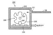
- FIG. 8 to 10 are diagrams for describing the internal structure of door switch 110 according to the present embodiment.
- FIG. 8 shows a state where the operation key 150 is removed
- FIG. 9 shows a state where the operation key 150 is inserted
- FIG. 10 shows a state when viewed from the top of FIG. 8 or FIG.
- door switch 110 includes a cam 230, a detection unit 240, and a substrate 250 for driving detection unit 240, and a housing 210 for housing them integrally. Is further provided.
- the cam 230 rotates around the rotation shaft 231 when the operation key 150 is inserted from the insertion port 211 formed in the housing 210.
- the detection unit 240 is an optical detection element such as a photomicro, for example, and is provided with a light projecting unit 241 and a light receiving unit 242 with a cam 230 interposed therebetween as shown in FIG.
- the operation key 150 is removed (that is, the door is opened)
- the light from the light projecting unit 241 is blocked by the cam 230 as shown in FIG.
- a detection signal is output.
- the notch 235 formed in the cam 230 moves to the position of the detection unit 240, thereby the light projecting unit.
- Light from 241 passes through and is detected by the light receiving unit 242.
- an ON detection signal is output from the door switch 110.
- the configuration in which the operation unit and the detection unit are housed in an integrated housing makes it possible to essentially eliminate the separation of the head unit and the switch unit as described above.
- the size of the entire switch can be reduced by configuring the detection unit using an electronic device such as a photomicro that can detect the operation state of the operation unit without a mechanism unit. As shown in FIG. This can alleviate dimensional restrictions in mounting the switch.
- a light projection part and a light-receiving part are not limited to the structure installed on both sides of a cam.
- a reflection type optical detection element in which the light projecting unit and the light receiving unit are integrated may be disposed at the position of the light projecting unit 241 in FIG. 10, and the reflector may be disposed at the position of the light receiving unit 242. Good. Or you may make it detect an operation state by the difference between the distance to a cam, and the distance to a housing
- the detection unit can use a magnetic detection element in addition to the optical detection element.
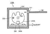
- 11 to 13 are diagrams for describing the internal structure of door switch 110A according to the present embodiment when a magnetic detection element is used.
- FIG. 11 shows a state where the operation key 150 is removed
- FIG. 12 shows a state where the operation key 150 is inserted.
- FIG. 13 shows a state when viewed from the top surface of FIG. 11 or FIG.
- the cam 230 and the detection unit 240 in the door switch 110 described in FIGS. 8 to 10 are replaced with the cam 230A and the detection unit 240A. 11 to 13, the description of the same elements as those in FIGS. 8 to 10 will not be repeated.
- a magnetic element 232 is attached to the cam 230A at a portion corresponding to the notch 235 formed in the cam 230 in FIG.
- a magnetic element 232 for example, a permanent magnet or a metal plate is used according to the type of the detection unit 240A.
- the detection unit 240A is a magnetic detection element, and outputs an ON detection signal when the magnetic element 232 approaches the detection unit 240A within a predetermined distance.
- magnetic detection elements include proximity sensors, Hall elements, and reed switches.
- the detection unit it is also possible to use a capacitive proximity sensor or a contact-type small micro switch in addition to the above.
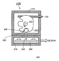
- FIG. 14 and FIG. 15 are diagrams for explaining an example of the door switch 110B when the internal components are divided and housed in two housings.
- the element which has the same function as FIG. 8 is attached
- door switch 110B has a structure in which an upper casing 215 and a lower casing 216 are coupled.
- the upper casing 215 accommodates a cam 230 and a detection unit 240 which are operation units.
- a substrate 250 for driving the detection unit 240 is accommodated in the lower housing 216.
- the detection unit 240 is connected to the substrate 250 through the wiring 245.
- the entire detection unit 240 is housed in the upper housing 215 .
- the light projecting unit of the detection unit 240 is housed in the upper housing 215 and the light receiving unit is installed in the lower housing. It may be configured to be housed in the housing 216. Even in this case, when the upper housing 215 and the lower housing 216 are separated, the light from the light projecting unit cannot be detected by the light receiving unit, so that an off detection signal is output as described above. .
- the size of the entire switch can be reduced by using the electronic device as the detection unit Even when the casing is separated due to breakage of the switch, safety can be ensured.
- FIG. 16 is a diagram showing an electrical connection between the door switch and the safety controller when the optical detection element described in FIG. 8 is used.
- door switch 110 includes a light projecting unit 241 and a light receiving unit 242 as detection units as described above.
- the light projecting unit 241 includes, for example, a light emitting diode 243 as a light receiving element.
- the anode of the light emitting diode is connected to the terminal T3, and the cathode is connected to the terminal T4.
- the light receiving unit 242 includes, for example, a phototransistor 244 as a light receiving element.
- the collector of the phototransistor is connected to the terminal T1, and the emitter is connected to the terminal T2.
- the safety controller 120 includes a power supply terminal V1 for supplying power to the light projecting unit 241, a power supply terminal Vcc for supplying power to the light receiving unit 242, and an input terminal for inputting a detection signal from the light receiving unit 242.
- IN and ground terminal GND are included.
- the power supply terminal V1 and the ground terminal GND are connected to the terminals T3 and T4 of the light projecting unit 241, respectively.
- the power supply terminal Vcc and the input terminal IN are connected to the terminals T1 and T2 of the light receiving unit 242, respectively.
- the power supply terminal V1 When the safety controller 120 is outside the monitoring period of the door switch 110, the power supply terminal V1 has a predetermined power supply voltage (for example, the same voltage as Vcc) in order to continuously emit light from the light projecting unit 241. Is applied continuously. If the light between the light projecting unit 241 and the light receiving unit 242 is in a light transmitting state, the phototransistor 244 is activated, and an ON detection signal (that is, a logic high signal) is input to the input terminal IN. Is done.
- a predetermined power supply voltage for example, the same voltage as Vcc
- the phototransistor 244 is deactivated and an OFF detection signal (that is, a logic low signal) is input to the input terminal IN. Entered.
- the safety controller 120 monitors the door switch 110, the safety controller 120 applies a voltage pulse that repeats application and stop of the power supply voltage in a predetermined periodic pattern to the power supply terminal V1. At this time, when the light between the light projecting unit 241 and the light receiving unit 242 is in a light-transmitting state, if the door switch 110 is normal, the input terminal IN corresponds to the voltage pulse applied to the power supply terminal V1. The pattern signal is input.
- the detection signal may remain on or off with respect to the applied voltage pulse. In this way, the monitoring function of the door switch 110 can be realized by comparing the applied voltage pulse with the input signal that has been input.
- the light between the light projecting unit 241 and the light receiving unit 242 is shielded, the light from the light projecting unit 241 is received by the light receiving unit 242 even if a voltage pulse is applied to the light projecting unit 241. In this case, it is impossible to detect whether the door switch 110 is abnormal. However, in such a light-shielded state, the operation key 150 is generally pulled out, and the power is not supplied to the motor 170 so that safety is maintained. It will not be.
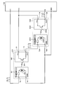
- FIG. 17 is a diagram showing an electrical connection between the door switch and the safety controller when a plurality of door switches are used, for example, when there are a plurality of entrances on the protective wall.
- a door switch 110 # is further added.
- door switch 110 # basically has the same structure as door switch 110.
- the terminal T1 # of the light receiving unit 242 # is connected to the power supply terminal Vcc of the safety controller 120, and the terminal T2 # is connected to the input terminal IN of the safety controller 120.
- the terminal T4 # of the light projecting unit 241 # is connected to the ground terminal GND of the safety controller 120.
- the terminal T3 # of the light projecting unit 241 # is connected to the terminal T2 of the door switch 110.
- the safety controller 120 can detect the abnormality.
- connection of the door switch is not limited to the connection method as shown in FIG. 17, for example, the light projecting unit is connected in parallel to the power supply terminal V1 and the ground terminal GND of the safety controller 120, and the light receiving unit As for, a system in which the safety controller 120 is connected in series between the power supply terminal Vcc and the input terminal IN may be used.
- the safety control system conforming to categories 1 and 3 of ISO 13849-1 has a configuration in which the input device and the logic operation device are duplicated, and has a cross monitoring function between the logic operation devices. Is required.
- FIG. 18 is a diagram showing a safety control system 10A using an interlock switch conforming to category 3 or 4 of ISO13849-1.
- control system 100 ⁇ / b> A includes door switch 180 including two detection units 181 and 182 instead of door switch 110 in FIG. 4, and safety corresponding to two detection units 181 and 182, respectively. Controllers 121 and 122 are provided.
- each safety controller and the detection unit are the same as the functions of the safety controller 120 and the door switch 110 in FIG. 4 and will not be repeated. However, the two safety controllers 121 and 122 cross each other to detect the presence or absence of the other party's abnormality. It also has a monitoring function.
- FIG. 19 and 20 are diagrams for explaining an example of the internal configuration of the door switch 180 having a plurality of such detection units.
- FIG. 19 shows a state in which the operation key 150 is pulled out, and FIG. A state in which the operation key 150 is inserted is shown.
- door switch 180 includes cams 260 in door switch 110 in FIG. 8 replaced with cams 260 and two detection units 181 and 182 in place of detection unit 240.
- Two notches 261 and 262 are formed in the cam 260.
- the detectors 181 and 182 are arranged at positions corresponding to the notches 261 and 262 when the operation key 150 is inserted and the cam 260 rotates. With such a configuration, it is possible to detect the operating state of the cam 260 as the operating unit by the two detecting units 181 and 182.
- the configuration in which the individual cutout portions 261 and 262 corresponding to the two detection units 181 and 182 are formed on the cam 260 has been described.
- the two detection units may be arranged adjacent to each other, and the operation state of the same notch may be detected by the two detection units.
- a control system corresponding to FIG. 18 is constructed by using two door switches having one detection unit shown in FIG. Therefore, it is possible to provide a safety control system conforming to the categories 3 and 4 of ISO13849-1.
- 10, 10A safety control system 100, 100A control system, 110, 110A, 110B, 180, 300 door switch, 120, 121, 122 safety controller, 130 power supply unit, 140 door, 150, 330 operation keys, 160 AC power supply , 170 motor, 181, 182, 240, 240A, 380 detector, 210, 215, 216, 310, 320 housing, 211, 311 insertion port, 230, 230A, 260, 340 cam, 231, 341 rotating shaft, 232 Magnetic element, 235, 261, 262, 342, notch, 241, 241 # light emitting unit, 242, 242 # light receiving unit, 243, 243 # light emitting diode, 244, 244 # phototransistor, 245 wiring, 250 substrate, 350 operation Working rod, 360 spring mechanism, 365 moving contact, 370 fixed contact, GND ground terminal, T1 to T4, T1 # to T4 # terminals, V1, Vcc power terminal.
Landscapes
- Mechanisms For Operating Contacts (AREA)
- Operating, Guiding And Securing Of Roll- Type Closing Members (AREA)
- Power-Operated Mechanisms For Wings (AREA)
Abstract
Description
好ましくは、検出要素は、フォトマイクロセンサである。
好ましくは、第1の筐体は、略立方体の形状を有する。
好ましくは、スイッチは、スイッチにおける異常の有無を監視するために、外部から供給される試験信号を入力するための入力部をさらに備える。そして、検出部は、異常が発生していない場合は、入力部で受けた試験信号に対応した信号を出力する。
図4は、ISO13849-1のカテゴリ2の基準に適合した、インターロックスイッチを用いた安全制御システム10の一般的な例を示す構成図である。図4を参照して、安全制御システム10は、交流電源160から、負荷であるモータ170への駆動電力の供給、および駆動電力の遮断を行なう。なお、図4においては、負荷としてモータを使用した構成を例として説明するが、電力を用いて動作するものであれば、負荷の構成はこれに限定されない。
次に図5~図7を用いて、従来のドアスイッチにおける問題点について説明する。図5を参照して、ドアスイッチ300は、動作部であるカム340を含む第1の筐体310と、操作ロッド350、バネ機構360および検出部380を含む第2の筐体320とを含んで構成される。検出部380は、移動接点365と固定接点370とを含む。
図8~図10は、本実施の形態に従うドアスイッチ110の内部構造を説明するための図である。図8は操作キー150が抜かれた状態を示し、図9は操作キー150が挿入された状態を示す。また、図10は、図8または図9の上面から見た場合の状態を示す。
なお、検出部については、上述のように投光部および受光部がカムを挟んで設置される構成には限定されない。たとえば、投光部と受光部とが一体となった反射型の光学式検出要素を図10における投光部241の位置に配置し、反射板を受光部242の位置に配置するようにしてもよい。あるいは、光学式の距離検出要素を用いて、カムまでの距離と筐体内壁までの距離との違いによって動作状態を検出するようにしてもよい。
上述の例においては、1つの筐体内に動作部、検出部、および基板を一体として収納する例について説明したが、本実施の形態のおいては、必ずしも1つの筐体とすることは必須ではない。
安全制御システムがISO13849-1のカテゴリ2に適合するためには、上述のように、入力機器すなわち図4においてはドアスイッチの監視機能が必要となる。
上記の説明においては、ISO13849-1のカテゴリ2に適合可能なドアスイッチについて説明した。
Claims (11)
- 第1の筐体と、
アクチュエータの操作によって動作する動作部と、
前記動作部の動作状態を検出するとともに、検出した前記動作状態に関する信号を出力するための検出部とを備え、
前記第1の筐体は、前記動作部および前記検出部の少なくとも一部を収納する、スイッチ。 - 前記アクチュエータは、キーを含み、
前記動作部は、前記キーが前記動作部の形状に対応した形状である場合は、前記第1の筐体への前記キーの挿入操作によって動作する一方で、前記キーが前記動作部の形状に対応した形状でない場合は、前記挿入操作によって動作しないように構成される、請求項1に記載のスイッチ。 - 前記検出部は、前記動作部の動作状態を光学的に検出するための検出要素を含む、請求項2に記載のスイッチ。
- 前記検出要素は、フォトマイクロセンサである、請求項3に記載のスイッチ。
- 前記動作部は、動作状態の場合に前記検出部の光を通光させる一方で、非動作状態の場合に前記光を遮光する、請求項3または4に記載のスイッチ。
- 前記検出部は、前記動作部の動作状態を磁気的に検出するための検出要素を含む、請求項2に記載のスイッチ。
- 前記第1の筐体は、略立方体の形状を有する、請求項1または2に記載のスイッチ。
- 前記第1の筐体と結合される第2の筐体をさらに備え、
前記検出部は、前記第1の筐体と前記第2の筐体とが分離された場合は、前記動作部が非動作状態を示す信号を出力する、請求項1~7のいずれか1項に記載のスイッチ。 - 前記検出部を駆動するための回路基板をさらに備え、
前記動作部および前記検出部は、前記第1の筐体に収納され、
前記回路基板は、前記第2の筐体に収納され、
前記検出部は、前記第1の筐体と前記第2の筐体とが分離された場合に、前記検出部と前記回路基板との間の信号伝達が遮断されたことによって、前記動作部が非動作状態を示す信号を出力する、請求項8に記載のスイッチ。 - 前記スイッチにおける異常の有無を監視するために、外部から供給される試験信号を入力するための入力部をさらに備え、
前記検出部は、異常が発生していない場合は、前記入力部で受けた前記試験信号に対応した信号を出力する、請求項1~9のいずれか1項に記載のスイッチ。 - 前記検出部は、少なくとも2つの検出要素を含む、請求項2に記載のスイッチ。
Priority Applications (4)
| Application Number | Priority Date | Filing Date | Title |
|---|---|---|---|
| CN201180024443.9A CN103155078B (zh) | 2010-09-17 | 2011-03-16 | 开关 |
| KR1020127030567A KR101454528B1 (ko) | 2010-09-17 | 2011-03-16 | 스위치 |
| US13/699,121 US9190226B2 (en) | 2010-09-17 | 2011-03-16 | Switch |
| EP11824816.0A EP2562782B1 (en) | 2010-09-17 | 2011-03-16 | Switch |
Applications Claiming Priority (2)
| Application Number | Priority Date | Filing Date | Title |
|---|---|---|---|
| JP2010-209264 | 2010-09-17 | ||
| JP2010209264A JP5195855B2 (ja) | 2010-09-17 | 2010-09-17 | スイッチ |
Publications (1)
| Publication Number | Publication Date |
|---|---|
| WO2012035803A1 true WO2012035803A1 (ja) | 2012-03-22 |
Family
ID=45831286
Family Applications (1)
| Application Number | Title | Priority Date | Filing Date |
|---|---|---|---|
| PCT/JP2011/056226 Ceased WO2012035803A1 (ja) | 2010-09-17 | 2011-03-16 | スイッチ |
Country Status (6)
| Country | Link |
|---|---|
| US (1) | US9190226B2 (ja) |
| EP (1) | EP2562782B1 (ja) |
| JP (1) | JP5195855B2 (ja) |
| KR (1) | KR101454528B1 (ja) |
| CN (1) | CN103155078B (ja) |
| WO (1) | WO2012035803A1 (ja) |
Families Citing this family (7)
| Publication number | Priority date | Publication date | Assignee | Title |
|---|---|---|---|---|
| US9496098B1 (en) * | 2014-01-31 | 2016-11-15 | Cooper Technologies Company | Control system |
| JP2019102236A (ja) * | 2017-11-30 | 2019-06-24 | 株式会社ヴァレオジャパン | スイッチ |
| CN109003411B (zh) * | 2018-08-27 | 2024-04-02 | 佛山市高明毅力温控器有限公司 | 一种防火探测报警器 |
| KR102272727B1 (ko) * | 2019-05-07 | 2021-07-07 | (주)네프 | 전력 제어 설비용 스위치 제어 장치 |
| EP4099567B1 (en) | 2021-05-31 | 2024-10-30 | Schneider Electric Industries SAS | Monitoring of magnetic sensing elements of a switching device |
| JP7820111B2 (ja) * | 2021-08-15 | 2026-02-25 | Idec株式会社 | パドロック対応型非常停止スイッチおよびこれを備えた安全制御システム |
| US12593815B2 (en) * | 2024-05-06 | 2026-04-07 | Kennel Automation LLC | Animal management system |
Citations (4)
| Publication number | Priority date | Publication date | Assignee | Title |
|---|---|---|---|---|
| JPH0961446A (ja) * | 1995-08-30 | 1997-03-07 | Fujitsu Ten Ltd | 衝撃センサ |
| JPH1092270A (ja) * | 1996-06-18 | 1998-04-10 | Kloeckner Moeller Gmbh | ポジションスイッチのための安全装置 |
| JP2010123306A (ja) * | 2008-11-18 | 2010-06-03 | Idec Corp | 安全スイッチ |
| JP2010157488A (ja) | 2008-12-02 | 2010-07-15 | Idec Corp | 安全スイッチ |
Family Cites Families (5)
| Publication number | Priority date | Publication date | Assignee | Title |
|---|---|---|---|---|
| DE19642862A1 (de) * | 1996-10-17 | 1998-04-30 | Kloeckner Moeller Gmbh | Sicherheitsvorrichtung für Positionsschalter |
| DE10000799C1 (de) * | 2000-01-11 | 2001-05-17 | Euchner Gmbh & Co | Vorrichtung zum Schalten einer elektrischen Verbindung in Abhängigkeit des Zustandes einer zu überwachenden Einrichtung, insbesondere Sicherheitsschalter |
| JP2002007059A (ja) * | 2000-06-27 | 2002-01-11 | Nagano Fujitsu Component Kk | 座標入力装置 |
| GB0519929D0 (en) | 2005-09-30 | 2005-11-09 | Eja Ltd | Safety switch |
| GB0705174D0 (en) * | 2007-03-17 | 2007-04-25 | Eja Ltd | Safety switch |
-
2010
- 2010-09-17 JP JP2010209264A patent/JP5195855B2/ja not_active Expired - Fee Related
-
2011
- 2011-03-16 US US13/699,121 patent/US9190226B2/en active Active
- 2011-03-16 KR KR1020127030567A patent/KR101454528B1/ko active Active
- 2011-03-16 EP EP11824816.0A patent/EP2562782B1/en not_active Not-in-force
- 2011-03-16 CN CN201180024443.9A patent/CN103155078B/zh not_active Expired - Fee Related
- 2011-03-16 WO PCT/JP2011/056226 patent/WO2012035803A1/ja not_active Ceased
Patent Citations (4)
| Publication number | Priority date | Publication date | Assignee | Title |
|---|---|---|---|---|
| JPH0961446A (ja) * | 1995-08-30 | 1997-03-07 | Fujitsu Ten Ltd | 衝撃センサ |
| JPH1092270A (ja) * | 1996-06-18 | 1998-04-10 | Kloeckner Moeller Gmbh | ポジションスイッチのための安全装置 |
| JP2010123306A (ja) * | 2008-11-18 | 2010-06-03 | Idec Corp | 安全スイッチ |
| JP2010157488A (ja) | 2008-12-02 | 2010-07-15 | Idec Corp | 安全スイッチ |
Non-Patent Citations (1)
| Title |
|---|
| See also references of EP2562782A4 |
Also Published As
| Publication number | Publication date |
|---|---|
| US20130233683A1 (en) | 2013-09-12 |
| JP2012064499A (ja) | 2012-03-29 |
| KR20130015003A (ko) | 2013-02-12 |
| CN103155078B (zh) | 2015-08-19 |
| JP5195855B2 (ja) | 2013-05-15 |
| KR101454528B1 (ko) | 2014-10-23 |
| US9190226B2 (en) | 2015-11-17 |
| EP2562782A4 (en) | 2014-12-03 |
| EP2562782B1 (en) | 2016-03-16 |
| CN103155078A (zh) | 2013-06-12 |
| EP2562782A1 (en) | 2013-02-27 |
Similar Documents
| Publication | Publication Date | Title |
|---|---|---|
| JP5195855B2 (ja) | スイッチ | |
| JP5407882B2 (ja) | 制御システム | |
| JP5728095B2 (ja) | 電気負荷をフェイルセーフに停止させるための安全開閉装置 | |
| EP2511737B1 (en) | Modular light curtain and plug-in module therefor | |
| US20090008232A1 (en) | Modular safety switching system and method | |
| US10310484B2 (en) | Device and method for failsafe monitoring of a moving machine part | |
| CN116783411A (zh) | 包括视觉状态指示器的线性致动器 | |
| CN104919561B (zh) | 安全切换装置 | |
| KR20070040391A (ko) | 회로 차단기 장치 | |
| JP2024525326A (ja) | 光学表示素子用の光学モニタリングシステム | |
| EP3667150A1 (en) | Interlocking device | |
| IT202200026397A1 (it) | Serratura reversibile | |
| JP3017190B1 (ja) | 製品容器開封履歴管理手段と管理方法 | |
| US10804058B2 (en) | Modular safety relay circuit for the safe control of at least one machine | |
| JP2019136733A (ja) | レーザ加工装置 | |
| US12518935B2 (en) | Safety switching device | |
| CN112596471B (zh) | 输入/输出系统 | |
| US20240355561A1 (en) | Safety switch for guarding accesses to machines or industrial plants and related assembly | |
| JP2008226604A (ja) | 押しボタンスイッチ | |
| KR20240154451A (ko) | 액세스부 보호용 안전 스위치, 관련 조립체 및 조립 방법 |
Legal Events
| Date | Code | Title | Description |
|---|---|---|---|
| WWE | Wipo information: entry into national phase |
Ref document number: 201180024443.9 Country of ref document: CN |
|
| 121 | Ep: the epo has been informed by wipo that ep was designated in this application |
Ref document number: 11824816 Country of ref document: EP Kind code of ref document: A1 |
|
| DPE1 | Request for preliminary examination filed after expiration of 19th month from priority date (pct application filed from 20040101) | ||
| WWE | Wipo information: entry into national phase |
Ref document number: 2011824816 Country of ref document: EP |
|
| ENP | Entry into the national phase |
Ref document number: 20127030567 Country of ref document: KR Kind code of ref document: A |
|
| NENP | Non-entry into the national phase |
Ref country code: DE |
|
| WWE | Wipo information: entry into national phase |
Ref document number: 13699121 Country of ref document: US |