WO2012035928A1 - ハイブリッド作業車両 - Google Patents
ハイブリッド作業車両 Download PDFInfo
- Publication number
- WO2012035928A1 WO2012035928A1 PCT/JP2011/068786 JP2011068786W WO2012035928A1 WO 2012035928 A1 WO2012035928 A1 WO 2012035928A1 JP 2011068786 W JP2011068786 W JP 2011068786W WO 2012035928 A1 WO2012035928 A1 WO 2012035928A1
- Authority
- WO
- WIPO (PCT)
- Prior art keywords
- motor
- vehicle
- speed
- traveling
- hybrid
- Prior art date
- Legal status (The legal status is an assumption and is not a legal conclusion. Google has not performed a legal analysis and makes no representation as to the accuracy of the status listed.)
- Ceased
Links
Images






Classifications
-
- B—PERFORMING OPERATIONS; TRANSPORTING
- B60—VEHICLES IN GENERAL
- B60K—ARRANGEMENT OR MOUNTING OF PROPULSION UNITS OR OF TRANSMISSIONS IN VEHICLES; ARRANGEMENT OR MOUNTING OF PLURAL DIVERSE PRIME-MOVERS IN VEHICLES; AUXILIARY DRIVES FOR VEHICLES; INSTRUMENTATION OR DASHBOARDS FOR VEHICLES; ARRANGEMENTS IN CONNECTION WITH COOLING, AIR INTAKE, GAS EXHAUST OR FUEL SUPPLY OF PROPULSION UNITS IN VEHICLES
- B60K6/00—Arrangement or mounting of plural diverse prime-movers for mutual or common propulsion, e.g. hybrid propulsion systems comprising electric motors and internal combustion engines
- B60K6/20—Arrangement or mounting of plural diverse prime-movers for mutual or common propulsion, e.g. hybrid propulsion systems comprising electric motors and internal combustion engines the prime-movers consisting of electric motors and internal combustion engines, e.g. HEVs
- B60K6/22—Arrangement or mounting of plural diverse prime-movers for mutual or common propulsion, e.g. hybrid propulsion systems comprising electric motors and internal combustion engines the prime-movers consisting of electric motors and internal combustion engines, e.g. HEVs characterised by apparatus, components or means specially adapted for HEVs
- B60K6/40—Arrangement or mounting of plural diverse prime-movers for mutual or common propulsion, e.g. hybrid propulsion systems comprising electric motors and internal combustion engines the prime-movers consisting of electric motors and internal combustion engines, e.g. HEVs characterised by apparatus, components or means specially adapted for HEVs characterised by the assembly or relative disposition of components
-
- E—FIXED CONSTRUCTIONS
- E02—HYDRAULIC ENGINEERING; FOUNDATIONS; SOIL SHIFTING
- E02F—DREDGING; SOIL-SHIFTING
- E02F3/00—Dredgers; Soil-shifting machines
- E02F3/04—Dredgers; Soil-shifting machines mechanically-driven
- E02F3/28—Dredgers; Soil-shifting machines mechanically-driven with digging tools mounted on a dipper- or bucket-arm, i.e. there is either one arm or a pair of arms, e.g. dippers, buckets
- E02F3/36—Component parts
-
- B—PERFORMING OPERATIONS; TRANSPORTING
- B60—VEHICLES IN GENERAL
- B60K—ARRANGEMENT OR MOUNTING OF PROPULSION UNITS OR OF TRANSMISSIONS IN VEHICLES; ARRANGEMENT OR MOUNTING OF PLURAL DIVERSE PRIME-MOVERS IN VEHICLES; AUXILIARY DRIVES FOR VEHICLES; INSTRUMENTATION OR DASHBOARDS FOR VEHICLES; ARRANGEMENTS IN CONNECTION WITH COOLING, AIR INTAKE, GAS EXHAUST OR FUEL SUPPLY OF PROPULSION UNITS IN VEHICLES
- B60K17/00—Arrangement or mounting of transmissions in vehicles
- B60K17/34—Arrangement or mounting of transmissions in vehicles for driving both front and rear wheels, e.g. four wheel drive vehicles
- B60K17/356—Arrangement or mounting of transmissions in vehicles for driving both front and rear wheels, e.g. four wheel drive vehicles having fluid or electric motor, for driving one or more wheels
-
- B—PERFORMING OPERATIONS; TRANSPORTING
- B60—VEHICLES IN GENERAL
- B60K—ARRANGEMENT OR MOUNTING OF PROPULSION UNITS OR OF TRANSMISSIONS IN VEHICLES; ARRANGEMENT OR MOUNTING OF PLURAL DIVERSE PRIME-MOVERS IN VEHICLES; AUXILIARY DRIVES FOR VEHICLES; INSTRUMENTATION OR DASHBOARDS FOR VEHICLES; ARRANGEMENTS IN CONNECTION WITH COOLING, AIR INTAKE, GAS EXHAUST OR FUEL SUPPLY OF PROPULSION UNITS IN VEHICLES
- B60K6/00—Arrangement or mounting of plural diverse prime-movers for mutual or common propulsion, e.g. hybrid propulsion systems comprising electric motors and internal combustion engines
-
- B—PERFORMING OPERATIONS; TRANSPORTING
- B60—VEHICLES IN GENERAL
- B60K—ARRANGEMENT OR MOUNTING OF PROPULSION UNITS OR OF TRANSMISSIONS IN VEHICLES; ARRANGEMENT OR MOUNTING OF PLURAL DIVERSE PRIME-MOVERS IN VEHICLES; AUXILIARY DRIVES FOR VEHICLES; INSTRUMENTATION OR DASHBOARDS FOR VEHICLES; ARRANGEMENTS IN CONNECTION WITH COOLING, AIR INTAKE, GAS EXHAUST OR FUEL SUPPLY OF PROPULSION UNITS IN VEHICLES
- B60K6/00—Arrangement or mounting of plural diverse prime-movers for mutual or common propulsion, e.g. hybrid propulsion systems comprising electric motors and internal combustion engines
- B60K6/20—Arrangement or mounting of plural diverse prime-movers for mutual or common propulsion, e.g. hybrid propulsion systems comprising electric motors and internal combustion engines the prime-movers consisting of electric motors and internal combustion engines, e.g. HEVs
-
- B—PERFORMING OPERATIONS; TRANSPORTING
- B60—VEHICLES IN GENERAL
- B60K—ARRANGEMENT OR MOUNTING OF PROPULSION UNITS OR OF TRANSMISSIONS IN VEHICLES; ARRANGEMENT OR MOUNTING OF PLURAL DIVERSE PRIME-MOVERS IN VEHICLES; AUXILIARY DRIVES FOR VEHICLES; INSTRUMENTATION OR DASHBOARDS FOR VEHICLES; ARRANGEMENTS IN CONNECTION WITH COOLING, AIR INTAKE, GAS EXHAUST OR FUEL SUPPLY OF PROPULSION UNITS IN VEHICLES
- B60K6/00—Arrangement or mounting of plural diverse prime-movers for mutual or common propulsion, e.g. hybrid propulsion systems comprising electric motors and internal combustion engines
- B60K6/20—Arrangement or mounting of plural diverse prime-movers for mutual or common propulsion, e.g. hybrid propulsion systems comprising electric motors and internal combustion engines the prime-movers consisting of electric motors and internal combustion engines, e.g. HEVs
- B60K6/22—Arrangement or mounting of plural diverse prime-movers for mutual or common propulsion, e.g. hybrid propulsion systems comprising electric motors and internal combustion engines the prime-movers consisting of electric motors and internal combustion engines, e.g. HEVs characterised by apparatus, components or means specially adapted for HEVs
- B60K6/36—Arrangement or mounting of plural diverse prime-movers for mutual or common propulsion, e.g. hybrid propulsion systems comprising electric motors and internal combustion engines the prime-movers consisting of electric motors and internal combustion engines, e.g. HEVs characterised by apparatus, components or means specially adapted for HEVs characterised by the transmission gearings
-
- B—PERFORMING OPERATIONS; TRANSPORTING
- B60—VEHICLES IN GENERAL
- B60K—ARRANGEMENT OR MOUNTING OF PROPULSION UNITS OR OF TRANSMISSIONS IN VEHICLES; ARRANGEMENT OR MOUNTING OF PLURAL DIVERSE PRIME-MOVERS IN VEHICLES; AUXILIARY DRIVES FOR VEHICLES; INSTRUMENTATION OR DASHBOARDS FOR VEHICLES; ARRANGEMENTS IN CONNECTION WITH COOLING, AIR INTAKE, GAS EXHAUST OR FUEL SUPPLY OF PROPULSION UNITS IN VEHICLES
- B60K6/00—Arrangement or mounting of plural diverse prime-movers for mutual or common propulsion, e.g. hybrid propulsion systems comprising electric motors and internal combustion engines
- B60K6/20—Arrangement or mounting of plural diverse prime-movers for mutual or common propulsion, e.g. hybrid propulsion systems comprising electric motors and internal combustion engines the prime-movers consisting of electric motors and internal combustion engines, e.g. HEVs
- B60K6/42—Arrangement or mounting of plural diverse prime-movers for mutual or common propulsion, e.g. hybrid propulsion systems comprising electric motors and internal combustion engines the prime-movers consisting of electric motors and internal combustion engines, e.g. HEVs characterised by the architecture of the hybrid electric vehicle
-
- B—PERFORMING OPERATIONS; TRANSPORTING
- B60—VEHICLES IN GENERAL
- B60K—ARRANGEMENT OR MOUNTING OF PROPULSION UNITS OR OF TRANSMISSIONS IN VEHICLES; ARRANGEMENT OR MOUNTING OF PLURAL DIVERSE PRIME-MOVERS IN VEHICLES; AUXILIARY DRIVES FOR VEHICLES; INSTRUMENTATION OR DASHBOARDS FOR VEHICLES; ARRANGEMENTS IN CONNECTION WITH COOLING, AIR INTAKE, GAS EXHAUST OR FUEL SUPPLY OF PROPULSION UNITS IN VEHICLES
- B60K6/00—Arrangement or mounting of plural diverse prime-movers for mutual or common propulsion, e.g. hybrid propulsion systems comprising electric motors and internal combustion engines
- B60K6/20—Arrangement or mounting of plural diverse prime-movers for mutual or common propulsion, e.g. hybrid propulsion systems comprising electric motors and internal combustion engines the prime-movers consisting of electric motors and internal combustion engines, e.g. HEVs
- B60K6/42—Arrangement or mounting of plural diverse prime-movers for mutual or common propulsion, e.g. hybrid propulsion systems comprising electric motors and internal combustion engines the prime-movers consisting of electric motors and internal combustion engines, e.g. HEVs characterised by the architecture of the hybrid electric vehicle
- B60K6/46—Series type
-
- B—PERFORMING OPERATIONS; TRANSPORTING
- B60—VEHICLES IN GENERAL
- B60K—ARRANGEMENT OR MOUNTING OF PROPULSION UNITS OR OF TRANSMISSIONS IN VEHICLES; ARRANGEMENT OR MOUNTING OF PLURAL DIVERSE PRIME-MOVERS IN VEHICLES; AUXILIARY DRIVES FOR VEHICLES; INSTRUMENTATION OR DASHBOARDS FOR VEHICLES; ARRANGEMENTS IN CONNECTION WITH COOLING, AIR INTAKE, GAS EXHAUST OR FUEL SUPPLY OF PROPULSION UNITS IN VEHICLES
- B60K6/00—Arrangement or mounting of plural diverse prime-movers for mutual or common propulsion, e.g. hybrid propulsion systems comprising electric motors and internal combustion engines
- B60K6/20—Arrangement or mounting of plural diverse prime-movers for mutual or common propulsion, e.g. hybrid propulsion systems comprising electric motors and internal combustion engines the prime-movers consisting of electric motors and internal combustion engines, e.g. HEVs
- B60K6/50—Architecture of the driveline characterised by arrangement or kind of transmission units
-
- B—PERFORMING OPERATIONS; TRANSPORTING
- B60—VEHICLES IN GENERAL
- B60K—ARRANGEMENT OR MOUNTING OF PROPULSION UNITS OR OF TRANSMISSIONS IN VEHICLES; ARRANGEMENT OR MOUNTING OF PLURAL DIVERSE PRIME-MOVERS IN VEHICLES; AUXILIARY DRIVES FOR VEHICLES; INSTRUMENTATION OR DASHBOARDS FOR VEHICLES; ARRANGEMENTS IN CONNECTION WITH COOLING, AIR INTAKE, GAS EXHAUST OR FUEL SUPPLY OF PROPULSION UNITS IN VEHICLES
- B60K6/00—Arrangement or mounting of plural diverse prime-movers for mutual or common propulsion, e.g. hybrid propulsion systems comprising electric motors and internal combustion engines
- B60K6/20—Arrangement or mounting of plural diverse prime-movers for mutual or common propulsion, e.g. hybrid propulsion systems comprising electric motors and internal combustion engines the prime-movers consisting of electric motors and internal combustion engines, e.g. HEVs
- B60K6/50—Architecture of the driveline characterised by arrangement or kind of transmission units
- B60K6/52—Driving a plurality of drive axles, e.g. four-wheel drive
-
- E—FIXED CONSTRUCTIONS
- E02—HYDRAULIC ENGINEERING; FOUNDATIONS; SOIL SHIFTING
- E02F—DREDGING; SOIL-SHIFTING
- E02F9/00—Component parts of dredgers or soil-shifting machines, not restricted to one of the kinds covered by groups E02F3/00 - E02F7/00
- E02F9/08—Superstructures; Supports for superstructures
- E02F9/0841—Articulated frame, i.e. having at least one pivot point between two travelling gear units
-
- E—FIXED CONSTRUCTIONS
- E02—HYDRAULIC ENGINEERING; FOUNDATIONS; SOIL SHIFTING
- E02F—DREDGING; SOIL-SHIFTING
- E02F9/00—Component parts of dredgers or soil-shifting machines, not restricted to one of the kinds covered by groups E02F3/00 - E02F7/00
- E02F9/08—Superstructures; Supports for superstructures
- E02F9/0858—Arrangement of component parts installed on superstructures not otherwise provided for, e.g. electric components, fenders, air-conditioning units
-
- E—FIXED CONSTRUCTIONS
- E02—HYDRAULIC ENGINEERING; FOUNDATIONS; SOIL SHIFTING
- E02F—DREDGING; SOIL-SHIFTING
- E02F9/00—Component parts of dredgers or soil-shifting machines, not restricted to one of the kinds covered by groups E02F3/00 - E02F7/00
- E02F9/20—Drives; Control devices
- E02F9/2058—Electric or electro-mechanical or mechanical control devices of vehicle sub-units
- E02F9/2062—Control of propulsion units
- E02F9/2075—Control of propulsion units of the hybrid type
-
- E—FIXED CONSTRUCTIONS
- E02—HYDRAULIC ENGINEERING; FOUNDATIONS; SOIL SHIFTING
- E02F—DREDGING; SOIL-SHIFTING
- E02F9/00—Component parts of dredgers or soil-shifting machines, not restricted to one of the kinds covered by groups E02F3/00 - E02F7/00
- E02F9/20—Drives; Control devices
- E02F9/2058—Electric or electro-mechanical or mechanical control devices of vehicle sub-units
- E02F9/2087—Control of vehicle steering
-
- B—PERFORMING OPERATIONS; TRANSPORTING
- B60—VEHICLES IN GENERAL
- B60K—ARRANGEMENT OR MOUNTING OF PROPULSION UNITS OR OF TRANSMISSIONS IN VEHICLES; ARRANGEMENT OR MOUNTING OF PLURAL DIVERSE PRIME-MOVERS IN VEHICLES; AUXILIARY DRIVES FOR VEHICLES; INSTRUMENTATION OR DASHBOARDS FOR VEHICLES; ARRANGEMENTS IN CONNECTION WITH COOLING, AIR INTAKE, GAS EXHAUST OR FUEL SUPPLY OF PROPULSION UNITS IN VEHICLES
- B60K1/00—Arrangement or mounting of electrical propulsion units
- B60K1/02—Arrangement or mounting of electrical propulsion units comprising more than one electric motor
-
- B—PERFORMING OPERATIONS; TRANSPORTING
- B60—VEHICLES IN GENERAL
- B60K—ARRANGEMENT OR MOUNTING OF PROPULSION UNITS OR OF TRANSMISSIONS IN VEHICLES; ARRANGEMENT OR MOUNTING OF PLURAL DIVERSE PRIME-MOVERS IN VEHICLES; AUXILIARY DRIVES FOR VEHICLES; INSTRUMENTATION OR DASHBOARDS FOR VEHICLES; ARRANGEMENTS IN CONNECTION WITH COOLING, AIR INTAKE, GAS EXHAUST OR FUEL SUPPLY OF PROPULSION UNITS IN VEHICLES
- B60K17/00—Arrangement or mounting of transmissions in vehicles
- B60K17/04—Arrangement or mounting of transmissions in vehicles characterised by arrangement, location or kind of gearing
- B60K17/043—Transmission unit disposed in on near the vehicle wheel, or between the differential gear unit and the wheel
-
- B—PERFORMING OPERATIONS; TRANSPORTING
- B60—VEHICLES IN GENERAL
- B60W—CONJOINT CONTROL OF VEHICLE SUB-UNITS OF DIFFERENT TYPE OR DIFFERENT FUNCTION; CONTROL SYSTEMS SPECIALLY ADAPTED FOR HYBRID VEHICLES; ROAD VEHICLE DRIVE CONTROL SYSTEMS FOR PURPOSES NOT RELATED TO THE CONTROL OF A PARTICULAR SUB-UNIT
- B60W2300/00—Indexing codes relating to the type of vehicle
- B60W2300/17—Construction vehicles, e.g. graders, excavators
-
- B—PERFORMING OPERATIONS; TRANSPORTING
- B60—VEHICLES IN GENERAL
- B60W—CONJOINT CONTROL OF VEHICLE SUB-UNITS OF DIFFERENT TYPE OR DIFFERENT FUNCTION; CONTROL SYSTEMS SPECIALLY ADAPTED FOR HYBRID VEHICLES; ROAD VEHICLE DRIVE CONTROL SYSTEMS FOR PURPOSES NOT RELATED TO THE CONTROL OF A PARTICULAR SUB-UNIT
- B60W2300/00—Indexing codes relating to the type of vehicle
- B60W2300/50—Tilting frame vehicles
-
- B—PERFORMING OPERATIONS; TRANSPORTING
- B60—VEHICLES IN GENERAL
- B60Y—INDEXING SCHEME RELATING TO ASPECTS CROSS-CUTTING VEHICLE TECHNOLOGY
- B60Y2200/00—Type of vehicle
- B60Y2200/40—Special vehicles
- B60Y2200/41—Construction vehicles, e.g. graders, excavators
- B60Y2200/415—Wheel loaders
-
- Y—GENERAL TAGGING OF NEW TECHNOLOGICAL DEVELOPMENTS; GENERAL TAGGING OF CROSS-SECTIONAL TECHNOLOGIES SPANNING OVER SEVERAL SECTIONS OF THE IPC; TECHNICAL SUBJECTS COVERED BY FORMER USPC CROSS-REFERENCE ART COLLECTIONS [XRACs] AND DIGESTS
- Y02—TECHNOLOGIES OR APPLICATIONS FOR MITIGATION OR ADAPTATION AGAINST CLIMATE CHANGE
- Y02T—CLIMATE CHANGE MITIGATION TECHNOLOGIES RELATED TO TRANSPORTATION
- Y02T10/00—Road transport of goods or passengers
- Y02T10/60—Other road transportation technologies with climate change mitigation effect
- Y02T10/62—Hybrid vehicles
-
- Y—GENERAL TAGGING OF NEW TECHNOLOGICAL DEVELOPMENTS; GENERAL TAGGING OF CROSS-SECTIONAL TECHNOLOGIES SPANNING OVER SEVERAL SECTIONS OF THE IPC; TECHNICAL SUBJECTS COVERED BY FORMER USPC CROSS-REFERENCE ART COLLECTIONS [XRACs] AND DIGESTS
- Y10—TECHNICAL SUBJECTS COVERED BY FORMER USPC
- Y10S—TECHNICAL SUBJECTS COVERED BY FORMER USPC CROSS-REFERENCE ART COLLECTIONS [XRACs] AND DIGESTS
- Y10S903/00—Hybrid electric vehicles, HEVS
- Y10S903/902—Prime movers comprising electrical and internal combustion motors
Definitions
- the present invention relates to a hybrid work vehicle, and is particularly suitable for an articulated hybrid work vehicle that is steered while deflecting the vehicle via a center joint.
- the drive part of a vehicle is electrified in a construction machine or the like, that is, the power source is an electric motor
- the power source is an electric motor
- hybrid engine high-efficiency driving
- power transmission efficiency improvement power transmission efficiency improvement
- regenerative power recovery Many energy saving effects can be expected.
- forklifts are most electrified, and “battery forklifts” that drive motors using battery power have been put into practical use ahead of other vehicles.
- “hybrid vehicles” combining a diesel engine and an electric motor have begun to be commercialized in hydraulic excavators, engine-type forklifts, and the like.
- wheel loaders are among the construction machines and work vehicles that are becoming more environmentally friendly and energy-saving through electrification, and vehicles that are expected to have a relatively large fuel consumption reduction effect when hybridized.
- the conventional wheel loader has a traveling part (wheel part) and a front hydraulic working part (lift / bucket part), and converts the power of the engine 1 to a torque converter (hereinafter referred to as torque converter).
- torque converter a torque converter
- This is a working vehicle that transports earth and sand etc. by the bucket portion of the hydraulic working device 5 of the front part using the hydraulic pump 4 as a drive source while traveling to the tire by the transmission 2 and the transmission (T / M) 3 .
- the currently most used wheel loader uses only an engine as a power source, and travel is driven by a torque converter 2 and a transmission (T / M) 3, and a front hydraulic working unit is driven by a hydraulic pump 4. Yes.
- the transmission efficiency of the torque converter 2 and the transmission 3 part can be improved to the transmission efficiency by electricity. Furthermore, since the wheel loader frequently repeats the starting and stopping traveling operations during work, the above-mentioned traveling drive part is electrified, and the energy at the time of braking, which was conventionally discharged as heat loss of the mechanical brake, is regenerated. As a result, it can be recovered and reused.
- the fuel consumption can be reduced by several tens of percent.
- Several configurations are conceivable for realizing the hybridization.
- the series hybrid type the power transmission path between the engine and the motor is connected to the series, that is, the generator is driven by the power of the engine and the electric motor is driven by the generated power.
- the parallel hybrid type uses a combination of an engine and a battery or a large-capacity capacitor power storage device, and directly assists the power of the engine with the power of the electric motor.
- various methods are employed for the transmission system of engine power assisted by the electric motor.
- a system combining torque converter and transmission T / M
- HST a system using a hydraulic drive device called HST.
- a configuration in which an electric transmission is performed by combining a planetary gear and an electric motor has been proposed.
- various system configurations are conceivable for hybrid machines, and when hybridization is performed in automobiles and construction machines, it is necessary to prepare an optimum hybrid configuration according to the work / operation content, equipment specifications, etc. It is.
- the work vehicles that are the subject of the present invention use the engine for the required power from the front hydraulic working device that occupies a relatively large proportion of power in addition to the power required for traveling.
- the assist method by the electric motor is relatively complicated, and it is considered effective to apply a series hybrid type that is not so popular in general automobiles.
- FIG. 11 shows a configuration example when a general series hybrid system is applied to the wheel loader.
- the configuration example shown in FIG. 11 is a hybrid configuration in which the traveling unit is electrified among the driving units of the wheel loader.
- the motor / generator (M / G) 6 is provided on the output shaft of the engine 1, the inverter 7 controls the motor, and the inverter 7.
- a traveling motor 9 attached to the output shaft (propeller shaft) 8 of the traveling unit and an inverter 10 for controlling the traveling motor 9 are mounted.
- the power storage device 11 is electrically connected to the inverters 7 and 10 through the DCDC converter 12, and receives DC power between these power converters.
- the power storage device 11 is described as an electric double-layer capacitor, and the DCDC converter 12 performs a step-up / step-down control of the capacitor voltage, and exchanges DC power with the power inverters 7 and 10.
- the hybrid wheel loader shown in FIG. 11 also includes a hydraulic pump 4 that supplies oil to a front hydraulic working device 5 that performs excavation work such as earth and sand as in the conventional machine shown in FIG. To implement.
- a hydraulic pump 4 that supplies oil to a front hydraulic working device 5 that performs excavation work such as earth and sand as in the conventional machine shown in FIG. To implement.
- the vehicle is driven to travel by the electric motor 9 for traveling mainly using the electric power generated by the motor / generator (M / G) 6 based on the power of the engine 1.
- M / G motor / generator
- the power storage device 11 can absorb regenerative power generated during braking of the vehicle and assist power (torque) with respect to the engine 1, thereby contributing to reduction of vehicle energy consumption.
- FIG. 12 shows an example of travel drive performance required for the wheel loader.
- a wheel loader generally requires a large driving force when it is stopped or at extremely low speeds in order to carry out excavation work such as transporting earth and sand while driving on a four-wheel wheel and driving into a natural ground. Drive to a vehicle speed of ⁇ 40km / h. Therefore, as shown in FIG. 12, the wheel loader is required to have a wide driving range driving performance, which is significantly different from the operating range required for a general industrial electric motor.
- a travel drive performance is to be realized by a hybrid system that travels with a single travel motor 9 as shown in FIG.
- Patent Document 1 discloses a traveling working machine including a traveling body and a working machine, a first electric motor, a second electric motor, A torque distribution transmission mechanism that receives the drive torques of the first and second electric motors and distributes and transmits the drive torque of the first and second electric motors to the drive shaft of the traveling body and the drive shaft of the work implement;
- a traveling work machine characterized by comprising: According to this, when operating the traveling body of the traveling work machine, the working machine using the electric motor as a driving source, the total capacity of the electric motor is reduced, and the driving force of the electric motor is distributed to each driving shaft, There is a description that by making the control contents simple, the apparatus cost can be reduced and the energy efficiency can be improved.
- the traveling work machine described in the above technology operates while distributing the power of the working hydraulic pump and the power of the traveling unit with two electric motors, control is performed so that power distribution is repeated as needed according to the operation mode of the machine. It is necessary to carry out the above, and the control content for realizing it is correspondingly complicated. Further, in the case where the traveling working machine is a hybrid machine that drives a generator by the power of the engine and drives the electric motor by the generated power, there is a possibility that the transmission efficiency may be lower than that of a conventional working machine.
- An object of the present invention is to provide a wheel-type work vehicle that operates with a front hydraulic working device while traveling with four-wheel tires such as a wheel loader, has a simple configuration, has good vehicle mounting properties, and is efficient.
- An object of the present invention is to provide a hybrid work vehicle that can transmit power well.
- the present invention provides an engine, a hydraulic pump driven by the engine, a working device disposed in front of the vehicle and performing work using the hydraulic pump as a drive source, and a rotational force of the engine.
- a hybrid work that has a motor / generator for generating electric power and a driving device for driving the vehicle by rotating the wheels by the electric power generated by the motor / generator, and steering the vehicle while refracting the vehicle via a center joint.
- the travel drive device includes a plurality of electric motors and a propeller shaft that is connected to the plurality of electric motors and transmits power from the plurality of electric motors to the wheels. And the plurality of electric motors are arranged back and forth across the center joint. It is characterized by being arranged him.
- each motor can be made smaller than when a wide range of travel drive performance is covered by a single motor. And can be easily mounted on a vehicle. Furthermore, in the present invention, since the plurality of electric motors are arranged separately at the front and rear with the center joint interposed therebetween, the balance of the weight of the vehicle is more than that when the plurality of electric motors are arranged on one side with the center joint interposed therebetween. Well, there is no need to change the design to mount the electric motor on the vehicle.
- the present invention it is only necessary to divide and mount a plurality of electric motors in empty spaces before and after the center joint of a conventional work vehicle.
- the present invention uses a plurality of electric motors as a power source, power can be transmitted more efficiently than a conventional work vehicle using only an engine as a power source.
- the plurality of electric motors include a high-speed electric motor having a characteristic capable of outputting torque from a low-speed region to a high-speed region, and torque in a low-speed region as compared with the high-speed motor.
- a low-speed motor having a characteristic that the torque in the high-speed range is small, but the low-speed motor is disposed on the rear side of the center joint, and the high-speed motor is disposed on the front side of the center joint. It is characterized by.
- the low-speed motor is generally larger.
- a counterweight is generally provided in order to balance the vehicle.
- the high-speed motor is disposed on the front side of the center joint. Since the low-speed motor larger than the high-speed motor is disposed on the rear side, the weight of the low-speed motor can be used as part of the counterweight.
- the high-speed electric motor in the present invention has a characteristic capable of outputting torque from a low-speed range to a high-speed range.
- the high-speed electric motor mainly has the driving performance required for high-speed driving of the vehicle. I have it.
- the low-speed motor in the present invention has a characteristic that the torque in the low-speed range is large but the torque in the high-speed range is small compared to the high-speed type motor. It has the required travel drive performance.
- the travel drive device is configured such that the overall efficiency of the plurality of electric motors is close to the maximum efficiency based on a travel output request value from the vehicle and each efficiency table of the plurality of electric motors.
- the torque of each of the plurality of electric motors is determined so as to have characteristics. According to the present invention, power can be transmitted more efficiently with simple control.
- a permanent magnet type synchronous motor is used as the low speed type electric motor, and an output shaft of the permanent magnet type synchronous motor is connected to the propeller shaft via a clutch, In a high-speed region where the permanent magnet type synchronous motor is in a revolving state, the clutch is released, and the output shaft of the permanent magnet type synchronous motor is mechanically separated from the propeller shaft. According to this invention, accompanying rotation is avoided, and the occurrence of extra losses during high speed traveling can be reduced.
- the present invention is characterized in that, in the above configuration, the low-speed electric motor is configured by combining the high-speed electric motor with a reduction gear configured with a predetermined gear ratio. According to the present invention, the low-speed motor can be reduced in size.
- the motor / generator is coaxially disposed in front of the engine, and the electric motor disposed behind the center joint is disposed below the motor / generator. It is characterized by that.
- the motor generator and the electric motor can be arranged using the space provided with the torque converter and the transmission in the conventional work vehicle only driven by the engine as it is, the design change for installing these devices can be made. This is unnecessary, and it becomes even easier to mount on the vehicle.
- the vehicle in a work vehicle such as a wheel loader or a dump truck that is operated by a front hydraulic working device while traveling with four-wheel tires, the vehicle can be easily mounted with a simple structure and efficiently powered.
- a hybrid work vehicle equipped with a hybrid system capable of transmission can be provided.
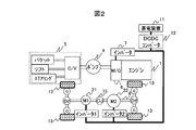
- FIG. 1 shows a configuration of a hybrid wheel loader provided with two traveling motors (motors) 21 and 22.
- the wheel loader shown in FIG. 1 is a series hybrid type wheel loader, which drives the engine 1 to rotate the traveling motors 21 and 22 by the electric power generated by the motor / generator 6, and the four wheels 13 are rotated by the rotation. It is the structure which drives a vehicle by rotating.
- the traveling motors 21 and 22 are arranged on or near the axis of the propeller shaft 8 to constitute a traveling drive device. When the traveling electric motors 21 and 22 rotate, the power is transmitted to the propeller shaft 8 and the wheels 13 are rotationally driven via the differential gear (Dif) and the gear (G).
- the wheel loader is an articulate type vehicle that is bent around the center of the vehicle to turn the steering, and a center joint (CJ) 15 is incorporated in a portion where the propeller shaft 8 is bent. 1 (FIG. 1) and a front frame 50 on the front side of the center joint 15 and a rear frame 60 on the rear side (see FIG. 13). Then, an electric motor (M1) 21 and an electric motor (M2) 22 are arranged as driving electric motors on the front and rear propeller shafts 8 with the center joint (CJ) 15 interposed therebetween.
- M1 electric motor
- M2 electric motor
- the electric motor (M1) 21 mounted on the front side of the vehicle body is provided on the front frame 50 side having a sufficient layout
- the electric motor (M2) 22 mounted on the rear side of the vehicle body is provided on the rear frame 60 side.
- the traveling motors 21 and 22 are disposed on the axis of the propeller shaft 8
- the traveling motors 21 and 22 having a hollow structure are used, and the propeller shaft 8 is inserted into the hollow portion, thereby What is necessary is just to connect a propeller shaft.
- the traveling motors 21 and 22 are disposed in the vicinity of the axis of the propeller shaft 8, the shafts of the traveling motors 21 and 22 and the propeller shaft 8 may be connected by a gear or the like.
- the hydraulic pump 4 is operated, and pressure oil is supplied from the hydraulic pump 4 to the hydraulic working device (working device) 5.
- the pressure oil supplied to the hydraulic working device 5 is supplied to the bucket, lift, and steering via the control valve C / V, and the bucket, The lift and steering can perform predetermined operations.
- the hybrid wheel loader shown in FIG. 1 distributes and drives the power required by the vehicle in a state where the output shafts of the two traveling motors 21 and 22 are mechanically connected.
- 22 can be configured with an electric motor having a smaller capacity than that when configured with one electric motor.
- the size of the electric motor (M2) 22 provided on the rear frame 60 side can be reduced compared to the case where the electric motor is configured with one traveling electric motor, and the mountability to the vehicle (degree of freedom of layout) is improved.
- the two traveling motors 21 and 22 are of the same specification, the two motors 21 and 22 are mechanically connected by the propeller shaft 8 as shown in FIG. What is necessary is just to make it output the motive power performed every 1/2 minute.
- the two traveling motors can be configured optimally with the respective motors having different driving characteristics as shown in FIG. Torque can be produced with the highest motor efficiency.
- the traveling motor 21 in front of the center joint 15 cannot output a large torque in the low speed range, but can be driven to a high speed (M1 characteristic, in FIG. 3).
- the traveling motor 22 behind the center joint 15 cannot output torque until it rotates at a high speed.
- a low-speed motor having a characteristic (M2 characteristic, dotted line in FIG. 3) that can generate a large torque is used.
- each motor having different characteristics has a different operation range in which it can be driven with high efficiency, and therefore, it is possible to drive the motor with high efficiency in a wide range of power performance required for the vehicle.
- Fig. 2 shows a configuration example of a hybrid wheel loader equipped with two electric motors with different characteristics.
- the traveling motor 21 is a high-speed motor
- the traveling motor 22 is a low-speed motor.
- the traveling motor 22 is larger than the traveling motor 21.
- the circle representing the traveling motor 22 is made larger than the circle representing the traveling motor 21. It is.
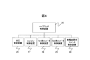
- FIG. 4 shows a configuration example of a controller that controls the hybrid wheel loader.
- the controller of FIG. 4 is incorporated in the travel drive device.
- the controller is provided with a hybrid control device 25 that manages the energy of the entire vehicle, and the hybrid control device 25 determines what output is used to drive each component.
- Each control device (26 to 30) in FIG. 4 controls each component in accordance with a command value relating to an output from the hybrid control device 25.
- FIG. 5 shows a torque determination method for each traveling motor of the hybrid system shown in FIG. 2 with such a controller configuration.
- an accelerator signal corresponding to an operation command from the operator, a brake signal, a forward / reverse SW signal, a current vehicle traveling speed, and the like are input, and a vehicle traveling output calculation is performed.
- a travel output command requested from the vehicle is calculated.
- the state quantity calculated here is described as output (power).
- the traveling speed of the vehicle the number of revolutions of the motor
- the traveling speed of the vehicle can be generally detected, it can be calculated by converting it into a torque state quantity. Good.
- the travel motor torque calculation 32 the calculated travel output command is used to calculate torques required for the travel motor (M1) 21 and the travel motor (M2) 22, respectively. At this time, when the required torques of the traveling motor (M1) 21 and the traveling motor (M2) 22 are totaled, the torque value corresponds to the traveling output command required by the vehicle.
- the traveling motor torque calculation 32 has efficiency data tables for the traveling motor (M1) 21 and the traveling motor (M2) 22 inside, and based on the efficiency data table, a traveling output command is generated. Determine the torque distribution for maximum motor efficiency.
- the limiter 33 uses the hybrid system and the vehicle.
- the torque restriction process based on the restriction items is performed to obtain the M1 torque command and the M2 torque command.
- Each of the M1 and M2 inverter control devices 28 and 29 drives the traveling motor (M1) 21 and the traveling motor (M2) 22 based on the M1 torque command and the M2 torque command, thereby performing a traveling operation of the vehicle.
- the two motors 21 and 22 having different characteristics are used to distribute the torque to the vehicle request so that the motor efficiency is maximized. It is possible to achieve an optimum capacity, and it is possible to achieve downsizing and high efficiency of the drive device.
- the type of the two traveling motors is not particularly limited.
- the two traveling motors 21 a and 22 a can both be constituted by induction machines.
- the high speed induction machine (IM1) 21a is installed in front of the center joint 15, and the low speed induction machine (IM2) 22a is installed in the rear of the center joint 15.
- the efficiency characteristic of the traveling motor 21a is the M1 characteristic shown in FIG. 3, and the efficiency characteristic of the traveling motor 22a is the M2 characteristic shown in FIG. If the hybrid configuration shown in FIG. 6 is used for high-speed running, the low-speed induction machine (IM2) 22a performs a follow-up operation.
- the reference numeral 22a is an induction machine
- the loss of loss can be reduced by stopping the excitation of the motor. It is possible to reduce the number of accompanying movements. From the above, it can be said that it is preferable to use an induction machine for the traveling motor mounted on the hybrid wheel loader because of the simplicity of control and the small loss during high-speed traveling.
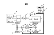
- FIG. 7 shows a hybrid configuration in the case of using a permanent magnet type synchronous motor.
- the high-speed synchronous machine (SM1) 21b is installed in front of the center joint 15, and the low-speed synchronous machine (SM2) 22b is installed in the rear of the center joint 15.
- the efficiency characteristic of the traveling motor 21b is the M1 characteristic shown in FIG. 3, and the efficiency characteristic of the traveling motor 22b is the M2 characteristic shown in FIG.
- the traveling motor is a permanent magnet type synchronous motor, the traveling motor can be made smaller than when the induction motor is mounted.
- the clutch 40 shown in FIG. 7 only releases the transmission of the output shaft of the traveling motor 22b, and the axle itself is configured to be connected to a four-wheel drive.
- the two traveling motors use the same type in each configuration, but an induction machine and a permanent magnet type synchronous motor are mixed. May be used.
- the induction machine usually has a small loss in the high speed range, and the permanent magnet type synchronous motor can efficiently generate a large torque in the low speed range.
- IM1 21a it is realistic that the low-speed type disposed behind the vehicle is configured by a synchronous machine (SM2) 22b.
- SM2 synchronous machine
- FIG. 9 This embodiment is a hybrid system in which high-speed induction machines (IM1) 21a and 21b are arranged at the rear of the vehicle as well as at the front of the vehicle.
- IM1 21a and 21b high-speed induction machines
- FIG. 9 the propeller shaft is connected to the high-speed induction machine (IM1) 21b at the rear of the vehicle via the speed reducer 41. Connect to 8 axes.
- the high-speed induction machine (IM1) 21b that can generate torque in the high-speed range is used, but the torque transmitted to the propeller shaft 8 is increased using the speed reducer 41 in order to generate a large torque in the low-speed range.
- the speed reducer 41 By using the speed reducer 41 in this way, it is possible to use electric motors having the same characteristics for the two traveling electric motors. As a result, it is possible to reduce the size of a low-speed motor that tends to be large.
- the torque determination method for each traveling motor in this embodiment can be realized by the control configuration shown in FIG.
- the traveling motor torque calculation 32 in FIG. 5 includes the rotational speed of the traveling motor at the front of the vehicle as well as at the rear of the vehicle. It is also necessary to input the actual rotational speed of the electric motor for traveling.
- the motor / generator (M / G) 6 constituting the hybrid system described in the above embodiment is arranged coaxially with the engine 1 corresponding to the position of the torque converter 2 of a conventional torque converter driven vehicle (see FIG. 10). Is possible. Further, the electric motor for traveling behind the vehicle can be mounted in the lower direction, that is, the position of the transmission 3 of the torque converter drive vehicle (see FIG. 10), and the electric components necessary for the hybrid system can be properly arranged. It becomes possible. Needless to say, the configuration of the above-described embodiment can be applied to a hybrid dump truck.
Landscapes
- Engineering & Computer Science (AREA)
- Mechanical Engineering (AREA)
- Chemical & Material Sciences (AREA)
- Combustion & Propulsion (AREA)
- Transportation (AREA)
- Mining & Mineral Resources (AREA)
- Civil Engineering (AREA)
- General Engineering & Computer Science (AREA)
- Structural Engineering (AREA)
- Hybrid Electric Vehicles (AREA)
- Electric Propulsion And Braking For Vehicles (AREA)
- Operation Control Of Excavators (AREA)
Abstract
Description
Claims (6)
- エンジンと、このエンジンで駆動される油圧ポンプと、車両前方に配置され前記油圧ポンプを駆動源として作業を行う作業装置と、前記エンジンの回転力により発電するモータ・ジェネレータと、このモータ・ジェネレータにより発電された電力により車輪を回転駆動して車両を走行させる走行駆動装置とを有し、センタージョイントを介して前記車両を屈折させながら操舵するハイブリッド作業車両において、
前記走行駆動装置は、複数の電動機と、これら複数の電動機と連結され、前記車輪に前記複数の電動機からの動力を伝達するプロペラシャフトとを備え、
前記複数の電動機は、前記センタージョイントを挟んで前後に分かれて配置される
ことを特徴とするハイブリッド作業車両。 - 請求項1の記載において、
前記複数の電動機は、低速域から高速域に亘ってトルクの出力が可能な特性を有する高速型電動機と、この高速型電動機に比べて低速域でのトルクは大きいものの高速域でのトルクは小さい特性を有する低速型電動機とを含み、
前記低速型電動機を前記センタージョイントの後方側に配置し、前記高速型電動機を前記センタージョイントの前方側に配置した
ことを特徴とするハイブリッド作業車両。 - 請求項2の記載において、
前記走行駆動装置は、前記車両からの走行出力要求値、ならびに前記複数の電動機の各効率テーブルに基づいて、前記複数の電動機の総合効率が最高効率近傍の特性となるように前記複数の電動機のそれぞれのトルクを決定する
ことを特徴とするハイブリッド作業車両。 - 請求項2または3の記載において、
前記低速型電動機として永久磁石型の同期モータが用いられ、前記永久磁石型の同期モータの出力軸は、クラッチを介して前記プロペラシャフトに連結されており、
前記永久磁石型の同期モータが連れまわり状態となる高速領域では、前記クラッチが開放され、前記永久磁石型の同期モータの出力軸は、前記プロペラシャフトから機械的に切り離される
ことを特徴とするハイブリッド作業車両。 - 請求項2または3の記載において、
前記低速型電動機は、前記高速型電動機に所定のギヤ比で構成される減速機を組み合わせた構成から成る
ことを特徴とするハイブリッド作業車両。 - 請求項1~5のいずれか1項の記載において、
前記モータ・ジェネレータは、前記エンジンの前方に同軸上に配置され、
前記センタージョイントの後方に配置された前記電動機は、前記モータ・ジェネレータの下方に配置される
ことを特徴とするハイブリッド作業車両。
Priority Applications (5)
| Application Number | Priority Date | Filing Date | Title |
|---|---|---|---|
| EP11824936.6A EP2617595B1 (en) | 2010-09-17 | 2011-08-19 | Hybrid work vehicle |
| US13/817,593 US9038759B2 (en) | 2010-09-17 | 2011-08-19 | Hybrid work vehicle |
| KR1020137003900A KR101755069B1 (ko) | 2010-09-17 | 2011-08-19 | 하이브리드 작업 차량 |
| CN201180040325.7A CN103052521B (zh) | 2010-09-17 | 2011-08-19 | 混合动力作业车辆 |
| KR1020177012500A KR101824853B1 (ko) | 2010-09-17 | 2011-08-19 | 하이브리드 작업 차량 |
Applications Claiming Priority (2)
| Application Number | Priority Date | Filing Date | Title |
|---|---|---|---|
| JP2010209449A JP5313986B2 (ja) | 2010-09-17 | 2010-09-17 | ハイブリッド作業車両 |
| JP2010-209449 | 2010-09-17 |
Publications (1)
| Publication Number | Publication Date |
|---|---|
| WO2012035928A1 true WO2012035928A1 (ja) | 2012-03-22 |
Family
ID=45831402
Family Applications (1)
| Application Number | Title | Priority Date | Filing Date |
|---|---|---|---|
| PCT/JP2011/068786 Ceased WO2012035928A1 (ja) | 2010-09-17 | 2011-08-19 | ハイブリッド作業車両 |
Country Status (6)
| Country | Link |
|---|---|
| US (1) | US9038759B2 (ja) |
| EP (1) | EP2617595B1 (ja) |
| JP (1) | JP5313986B2 (ja) |
| KR (2) | KR101824853B1 (ja) |
| CN (1) | CN103052521B (ja) |
| WO (1) | WO2012035928A1 (ja) |
Cited By (1)
| Publication number | Priority date | Publication date | Assignee | Title |
|---|---|---|---|---|
| CN106661868A (zh) * | 2014-05-06 | 2017-05-10 | 伊顿公司 | 具有静液选择的液压混合推进回路和操作方法 |
Families Citing this family (30)
| Publication number | Priority date | Publication date | Assignee | Title |
|---|---|---|---|---|
| JP5559119B2 (ja) * | 2011-09-22 | 2014-07-23 | 日立建機株式会社 | ホイールローダ |
| US8965609B2 (en) * | 2011-12-29 | 2015-02-24 | Kawasaki Jukogyo Kabushiki Kaisha | Electric vehicle |
| CN104203799B (zh) | 2012-01-09 | 2016-08-24 | 伊顿公司 | 用于工作机器的推进回路和工作回路组合 |
| KR101608264B1 (ko) * | 2012-03-28 | 2016-04-01 | 가부시끼 가이샤 구보다 | 하이브리드 작업차 |
| JP2013255366A (ja) * | 2012-06-07 | 2013-12-19 | Hitachi Constr Mach Co Ltd | 電動式走行車両 |
| JP2014007780A (ja) * | 2012-06-21 | 2014-01-16 | Hitachi Constr Mach Co Ltd | ハイブリッド式作業車両 |
| JP6014463B2 (ja) | 2012-11-07 | 2016-10-25 | 日立建機株式会社 | 作業車両 |
| JP5887288B2 (ja) * | 2013-02-04 | 2016-03-16 | 日立建機株式会社 | ホイールローダ |
| JP6046577B2 (ja) * | 2013-09-06 | 2016-12-21 | トヨタ自動車株式会社 | 制御装置、および、これを用いた車両 |
| US9067484B2 (en) * | 2013-10-23 | 2015-06-30 | Dezhou David Zhao | Electric vehicle control systems |
| US20150197239A1 (en) * | 2014-01-14 | 2015-07-16 | Deere & Company | Modular powertrain with multiple motors |
| KR102130179B1 (ko) | 2014-01-16 | 2020-07-03 | 두산인프라코어 주식회사 | 하이브리드 건설기계의 휠 구동장치 및 휠 구동방법 |
| US9649923B2 (en) | 2014-01-21 | 2017-05-16 | Interactive Fully Electrical Vehicles, S.R.L. | Electric-propulsion vehicle |
| ES2627329T3 (es) * | 2014-04-14 | 2017-07-27 | Iveco France S.A. | Vehículo articulado para el transporte de pasajeros con un sistema de accionamiento mejorado. |
| KR102181294B1 (ko) * | 2014-05-27 | 2020-11-20 | 두산인프라코어 주식회사 | 건설기계를 위한 휠 구동 시스템 |
| JP6433687B2 (ja) * | 2014-06-03 | 2018-12-05 | 株式会社Kcm | ハイブリッド式ホイールローダ |
| KR101588790B1 (ko) * | 2014-07-29 | 2016-01-26 | 현대자동차 주식회사 | 하이브리드 차량의 변속 제어 장치 |
| CN107000564B (zh) | 2014-10-27 | 2019-12-24 | 伊顿智能动力有限公司 | 具有静流体选择的液压混合推进回路以及操作方法 |
| CN105502230B (zh) * | 2016-01-21 | 2017-10-27 | 安徽农业大学 | 一种混合动力叉车传动系统 |
| DE102017119256A1 (de) * | 2017-08-23 | 2019-02-28 | Fraport Ag Frankfurt Airport Services Worldwide | Einsatz- oder Nutzfahrzeug für ein räumlich begrenztes Einsatzgebiet |
| JP7146168B2 (ja) * | 2018-03-20 | 2022-10-04 | マツダ株式会社 | 車両駆動装置 |
| US11084369B2 (en) * | 2019-02-26 | 2021-08-10 | Deere & Company | Hybrid transmission module for work vehicles |
| EP4007705A4 (en) | 2019-08-01 | 2023-08-16 | System73 Limited | MULTI-MOTOR SHIFTING SYSTEM AND PROCESSES FOR OPTIMIZED PERFORMANCE |
| US11524676B2 (en) | 2019-11-22 | 2022-12-13 | Shem, Llc | System and method for two step motor for electric vehicle (EV) truck and commercial vehicle applications |
| DE102020207831A1 (de) | 2020-06-24 | 2021-12-30 | Zf Friedrichshafen Ag | Verfahren zum Betreiben eines elektrischen Antriebsstrangs einer Arbeitsmaschine, elektrischer Antriebsstrang für eine Arbeitsmaschine und Arbeitsmaschine |
| US11498548B2 (en) | 2020-11-02 | 2022-11-15 | Deere & Company | Intelligent hybrid powertrain systems for combine harvesters |
| US12017633B2 (en) | 2021-03-24 | 2024-06-25 | Deere & Company | Intelligent power allocation systems onboard hybrid combines and associated methods |
| US20220379872A1 (en) * | 2021-05-26 | 2022-12-01 | Ford Global Technologies, Llc | Electrified vehicle control with distribution of powertrain torque to secondary axle |
| CN114834262B (zh) * | 2022-03-31 | 2025-07-15 | 江苏电子信息职业学院 | 独立电驱动加装离合器型装载机驱动控制系统及方法 |
| CN114834261B (zh) * | 2022-03-31 | 2025-07-15 | 江苏电子信息职业学院 | 节能型独立电驱动装载机驱动控制系统及方法 |
Citations (7)
| Publication number | Priority date | Publication date | Assignee | Title |
|---|---|---|---|---|
| JPH1199838A (ja) * | 1997-09-30 | 1999-04-13 | Fuji Heavy Ind Ltd | ハイブリッド自動車の駆動装置 |
| JP2002046494A (ja) * | 2000-08-04 | 2002-02-12 | Tcm Corp | 産業用車両 |
| JP2003284208A (ja) * | 2002-03-22 | 2003-10-03 | Tcm Corp | 電気式荷役車両 |
| JP2006205777A (ja) | 2005-01-25 | 2006-08-10 | Komatsu Ltd | 走行作業機械 |
| JP2008263920A (ja) * | 2007-04-24 | 2008-11-06 | Kanzaki Kokyukoki Mfg Co Ltd | 乗用型芝刈り車両 |
| JP2009241830A (ja) * | 2008-03-31 | 2009-10-22 | Komatsu Ltd | 走行作業車両 |
| JP2010030599A (ja) * | 2001-04-12 | 2010-02-12 | Komatsu Ltd | ホイールローダ |
Family Cites Families (30)
| Publication number | Priority date | Publication date | Assignee | Title |
|---|---|---|---|---|
| US2600897A (en) * | 1949-04-08 | 1952-06-17 | Berton M Mathias | Drive motor control for engine electric driven vehicles |
| US3334702A (en) * | 1964-12-14 | 1967-08-08 | Int Harvester Co | Four wheel drive articulated vehicle with means to transfer power between the wheels |
| JPS5871223A (ja) | 1981-10-22 | 1983-04-27 | Hino Motors Ltd | 動力可変式自動車 |
| JP3206038B2 (ja) | 1991-10-21 | 2001-09-04 | 株式会社日立製作所 | 電気自動車の制御装置 |
| US5586613A (en) * | 1993-04-22 | 1996-12-24 | The Texas A&M University System | Electrically peaking hybrid system and method |
| JPH07250403A (ja) * | 1994-03-09 | 1995-09-26 | Mazda Motor Corp | 電気車の制御装置 |
| JP3295046B2 (ja) * | 1998-12-21 | 2002-06-24 | ティー・シー・エム株式会社 | 駆動装置内蔵車輪式車両 |
| JP2001103605A (ja) * | 1999-09-30 | 2001-04-13 | Tcm Corp | 電動走行式産業用車両 |
| JP3539358B2 (ja) * | 2000-06-09 | 2004-07-07 | 日産自動車株式会社 | 車両の駆動力制御装置 |
| JP3652223B2 (ja) * | 2000-07-18 | 2005-05-25 | Tcm株式会社 | 電動走行式産業用車両 |
| US7379797B2 (en) * | 2001-01-31 | 2008-05-27 | Oshkosh Truck Corporation | System and method for braking in an electric vehicle |
| JP3961281B2 (ja) * | 2001-12-25 | 2007-08-22 | 富士重工業株式会社 | 自動車の差動機構 |
| JP3874347B2 (ja) | 2002-04-19 | 2007-01-31 | 株式会社ジェイテクト | 四輪駆動車両 |
| US7520354B2 (en) * | 2002-05-02 | 2009-04-21 | Oshkosh Truck Corporation | Hybrid vehicle with combustion engine/electric motor drive |
| US6880651B2 (en) * | 2003-05-14 | 2005-04-19 | Singapore Technologies Kinetics Ltd. | Articulated vehicle, an articulation device and a drive transmission |
| JP4386256B2 (ja) * | 2003-10-28 | 2009-12-16 | 日立建機株式会社 | ハイブリッド式建設車両 |
| US7469761B2 (en) * | 2004-06-28 | 2008-12-30 | Caterpillar Inc. | Continuously variable transmission system with power boost |
| US7325636B2 (en) * | 2004-08-30 | 2008-02-05 | Caterpillar Inc. | Front-wheel drive steering compensation method and system |
| US7441623B2 (en) * | 2005-02-28 | 2008-10-28 | Caterpillar Inc. | Multi-motor drive system for a work machine |
| US7950481B2 (en) * | 2005-09-29 | 2011-05-31 | Caterpillar Inc. | Electric powertrain for machine |
| KR101393660B1 (ko) * | 2005-10-14 | 2014-05-13 | 볼보 컨스트럭션 이큅먼트 에이비 | 작업기계 |
| WO2007043924A1 (en) * | 2005-10-14 | 2007-04-19 | Volvo Construction Equipment Ab | A working machine and a method for operating a working machine |
| JP4967314B2 (ja) * | 2005-11-09 | 2012-07-04 | トヨタ自動車株式会社 | 駆動装置 |
| EP1985487B1 (en) * | 2007-04-24 | 2018-08-08 | Kanzaki Kokyukoki Mfg. Co., Ltd. | Riding lawn mower |
| US9242633B2 (en) * | 2007-05-10 | 2016-01-26 | Volvo Construction Equipment Ab | Method and a control system for controlling a work machine |
| US8075435B2 (en) * | 2008-08-22 | 2011-12-13 | Caterpillar Inc. | Dual mode input split compound split configuration EPPV transmission |
| EP2367711B1 (en) * | 2008-11-21 | 2019-08-07 | Volvo Construction Equipment AB | Pedal map shift |
| JP5220679B2 (ja) * | 2009-04-20 | 2013-06-26 | 住友重機械工業株式会社 | ハイブリッド型作業機械及びハイブリッド型作業機械の制御方法 |
| US8672069B2 (en) * | 2009-08-25 | 2014-03-18 | Deere & Company | Hybrid vehicle with multiple electric drive systems |
| US8626368B2 (en) * | 2010-09-07 | 2014-01-07 | Caterpillar Inc. | Electric drive power response management system and method |
-
2010
- 2010-09-17 JP JP2010209449A patent/JP5313986B2/ja not_active Expired - Fee Related
-
2011
- 2011-08-19 CN CN201180040325.7A patent/CN103052521B/zh not_active Expired - Fee Related
- 2011-08-19 KR KR1020177012500A patent/KR101824853B1/ko not_active Expired - Fee Related
- 2011-08-19 WO PCT/JP2011/068786 patent/WO2012035928A1/ja not_active Ceased
- 2011-08-19 US US13/817,593 patent/US9038759B2/en active Active
- 2011-08-19 KR KR1020137003900A patent/KR101755069B1/ko not_active Expired - Fee Related
- 2011-08-19 EP EP11824936.6A patent/EP2617595B1/en not_active Not-in-force
Patent Citations (7)
| Publication number | Priority date | Publication date | Assignee | Title |
|---|---|---|---|---|
| JPH1199838A (ja) * | 1997-09-30 | 1999-04-13 | Fuji Heavy Ind Ltd | ハイブリッド自動車の駆動装置 |
| JP2002046494A (ja) * | 2000-08-04 | 2002-02-12 | Tcm Corp | 産業用車両 |
| JP2010030599A (ja) * | 2001-04-12 | 2010-02-12 | Komatsu Ltd | ホイールローダ |
| JP2003284208A (ja) * | 2002-03-22 | 2003-10-03 | Tcm Corp | 電気式荷役車両 |
| JP2006205777A (ja) | 2005-01-25 | 2006-08-10 | Komatsu Ltd | 走行作業機械 |
| JP2008263920A (ja) * | 2007-04-24 | 2008-11-06 | Kanzaki Kokyukoki Mfg Co Ltd | 乗用型芝刈り車両 |
| JP2009241830A (ja) * | 2008-03-31 | 2009-10-22 | Komatsu Ltd | 走行作業車両 |
Non-Patent Citations (1)
| Title |
|---|
| See also references of EP2617595A4 |
Cited By (2)
| Publication number | Priority date | Publication date | Assignee | Title |
|---|---|---|---|---|
| CN106661868A (zh) * | 2014-05-06 | 2017-05-10 | 伊顿公司 | 具有静液选择的液压混合推进回路和操作方法 |
| CN106661868B (zh) * | 2014-05-06 | 2019-05-10 | 伊顿公司 | 具有静液选择的液压混合推进回路和操作方法 |
Also Published As
| Publication number | Publication date |
|---|---|
| KR101824853B1 (ko) | 2018-02-01 |
| EP2617595A1 (en) | 2013-07-24 |
| EP2617595B1 (en) | 2018-01-24 |
| KR20170055561A (ko) | 2017-05-19 |
| EP2617595A4 (en) | 2016-10-12 |
| US9038759B2 (en) | 2015-05-26 |
| KR101755069B1 (ko) | 2017-07-06 |
| US20130149093A1 (en) | 2013-06-13 |
| JP2012062003A (ja) | 2012-03-29 |
| CN103052521A (zh) | 2013-04-17 |
| KR20130097727A (ko) | 2013-09-03 |
| CN103052521B (zh) | 2016-04-13 |
| JP5313986B2 (ja) | 2013-10-09 |
Similar Documents
| Publication | Publication Date | Title |
|---|---|---|
| JP5313986B2 (ja) | ハイブリッド作業車両 | |
| US7950481B2 (en) | Electric powertrain for machine | |
| CN101253349B (zh) | 行星式传动装置 | |
| US8702560B2 (en) | Construction machine | |
| EP2427357B1 (en) | A working machine and a method for operating a working machine | |
| US10272900B2 (en) | Hybrid wheel loader | |
| WO2008042319A2 (en) | Energy storage and recovery for a tracked machine | |
| JP5848727B2 (ja) | ハイブリッドホイールローダ | |
| CN1810557A (zh) | 一种油-电混合动力汽车的多桥驱动系统 | |
| CN103434389A (zh) | 具有直驶助力机构的履带车辆电传动装置 | |
| CN102133855A (zh) | 一种双侧独立驱动车辆主辅电机动力耦合总成 | |
| KR20150136366A (ko) | 건설기계를 위한 휠 구동 시스템 | |
| US20120018236A1 (en) | Electric powertrain for off-highway trucks | |
| JP5086667B2 (ja) | ハイブリッド車両 | |
| US20130240279A1 (en) | Hybrid tandem drive axle of a truck vehicle | |
| KR20140034547A (ko) | 연비성능 향상을 위한 하이브리드 지게차 시스템 | |
| JP5781050B2 (ja) | 鉄道車両用駆動装置 | |
| CN102139626A (zh) | 一种车辆用混合动力系统 | |
| JP2013144504A (ja) | ホイール式建設機械 |
Legal Events
| Date | Code | Title | Description |
|---|---|---|---|
| WWE | Wipo information: entry into national phase |
Ref document number: 201180040325.7 Country of ref document: CN |
|
| 121 | Ep: the epo has been informed by wipo that ep was designated in this application |
Ref document number: 11824936 Country of ref document: EP Kind code of ref document: A1 |
|
| ENP | Entry into the national phase |
Ref document number: 20137003900 Country of ref document: KR Kind code of ref document: A |
|
| WWE | Wipo information: entry into national phase |
Ref document number: 13817593 Country of ref document: US |
|
| WWE | Wipo information: entry into national phase |
Ref document number: 2011824936 Country of ref document: EP |
|
| NENP | Non-entry into the national phase |
Ref country code: DE |