WO2012036234A1 - 環境情報計測装置、環境情報計測システム、及び環境情報計測方法 - Google Patents
環境情報計測装置、環境情報計測システム、及び環境情報計測方法 Download PDFInfo
- Publication number
- WO2012036234A1 WO2012036234A1 PCT/JP2011/071099 JP2011071099W WO2012036234A1 WO 2012036234 A1 WO2012036234 A1 WO 2012036234A1 JP 2011071099 W JP2011071099 W JP 2011071099W WO 2012036234 A1 WO2012036234 A1 WO 2012036234A1
- Authority
- WO
- WIPO (PCT)
- Prior art keywords
- environmental information
- unit
- voltage
- time
- power supply
- Prior art date
- Legal status (The legal status is an assumption and is not a legal conclusion. Google has not performed a legal analysis and makes no representation as to the accuracy of the status listed.)
- Ceased
Links
Images







Classifications
-
- G—PHYSICS
- G01—MEASURING; TESTING
- G01D—MEASURING NOT SPECIALLY ADAPTED FOR A SPECIFIC VARIABLE; ARRANGEMENTS FOR MEASURING TWO OR MORE VARIABLES NOT COVERED IN A SINGLE OTHER SUBCLASS; TARIFF METERING APPARATUS; MEASURING OR TESTING NOT OTHERWISE PROVIDED FOR
- G01D9/00—Recording measured values
- G01D9/005—Solid-state data loggers
-
- G—PHYSICS
- G01—MEASURING; TESTING
- G01K—MEASURING TEMPERATURE; MEASURING QUANTITY OF HEAT; THERMALLY-SENSITIVE ELEMENTS NOT OTHERWISE PROVIDED FOR
- G01K1/00—Details of thermometers not specially adapted for particular types of thermometer
- G01K1/02—Means for indicating or recording specially adapted for thermometers
- G01K1/024—Means for indicating or recording specially adapted for thermometers for remote indication
-
- G—PHYSICS
- G01—MEASURING; TESTING
- G01K—MEASURING TEMPERATURE; MEASURING QUANTITY OF HEAT; THERMALLY-SENSITIVE ELEMENTS NOT OTHERWISE PROVIDED FOR
- G01K7/00—Measuring temperature based on the use of electric or magnetic elements directly sensitive to heat ; Power supply therefor, e.g. using thermoelectric elements
- G01K7/16—Measuring temperature based on the use of electric or magnetic elements directly sensitive to heat ; Power supply therefor, e.g. using thermoelectric elements using resistive elements
- G01K7/22—Measuring temperature based on the use of electric or magnetic elements directly sensitive to heat ; Power supply therefor, e.g. using thermoelectric elements using resistive elements the element being a non-linear resistance, e.g. thermistor
-
- G—PHYSICS
- G01—MEASURING; TESTING
- G01R—MEASURING ELECTRIC VARIABLES; MEASURING MAGNETIC VARIABLES
- G01R27/00—Arrangements for measuring resistance, reactance, impedance, or electric characteristics derived therefrom
- G01R27/02—Measuring real or complex resistance, reactance, impedance, or other two-pole characteristics derived therefrom, e.g. time constant
- G01R27/26—Measuring inductance or capacitance; Measuring quality factor, e.g. by using the resonance method; Measuring loss factor; Measuring dielectric constants ; Measuring impedance or related variables
- G01R27/2605—Measuring capacitance
-
- H—ELECTRICITY
- H04—ELECTRIC COMMUNICATION TECHNIQUE
- H04Q—SELECTING
- H04Q9/00—Arrangements in telecontrol or telemetry systems for selectively calling a substation from a main station, in which substation desired apparatus is selected for applying a control signal thereto or for obtaining measured values therefrom
-
- G—PHYSICS
- G01—MEASURING; TESTING
- G01K—MEASURING TEMPERATURE; MEASURING QUANTITY OF HEAT; THERMALLY-SENSITIVE ELEMENTS NOT OTHERWISE PROVIDED FOR
- G01K2219/00—Thermometers with dedicated analog to digital converters
-
- H—ELECTRICITY
- H04—ELECTRIC COMMUNICATION TECHNIQUE
- H04Q—SELECTING
- H04Q2209/00—Arrangements in telecontrol or telemetry systems
- H04Q2209/80—Arrangements in the sub-station, i.e. sensing device
- H04Q2209/88—Providing power supply at the sub-station
- H04Q2209/886—Providing power supply at the sub-station using energy harvesting, e.g. solar, wind or mechanical
Definitions
- the present invention relates to an environmental information measuring device, an environmental information measuring system, and an environmental information measuring method capable of measuring environmental information of a measurement target location.
- the environmental information to be measured includes information such as temperature, humidity, and atmospheric pressure, and the environmental information measuring device measures the information.
- Various measurement methods capable of corresponding to information to be measured are known.
- a method using an infrared camera is known as a method for measuring the temperature of the measurement target without contact (see Non-Patent Document 1).
- a method using a temperature indicating label is known as a method using a temperature indicating label.
- the method using the temperature label it is necessary to visually detect the display color, and the measurer approaches the position where the temperature label can be confirmed.
- temperature management of transmission lines and distribution lines in the power system for example, temperature management of connection points of transmission lines and distribution lines
- temperature management of feeder lines for supplying power to train lines for example, feeder lines
- Management of the temperature at the connection point The locations to be measured are distributed over a wide range, and it is necessary to repeatedly measure and the measurement frequency is highly demanded.
- the distance between the measurement location and the measurement target can be measured.
- an infrared camera is installed at a fixed point for each measurement location, the required equipment scale becomes large and difficult to implement.
- the measurer needs to point the infrared camera at the measurement target.
- the measurement time for each location also becomes longer.
- the method using the temperature indication label requires that the measurer approaches and observes the position where the display color can be visually confirmed. Applicable conditions may be limited. Therefore, by using the recording apparatus described in Patent Document 1, it is possible to reduce the work amount of the measurer and to perform measurement safely.
- the present invention has been made in view of such circumstances, and an object of the present invention is to measure environmental information of a measurement target location and to have low power consumption, an environmental information measuring device, an environmental information measuring system, and an environment. It is to provide an information measurement method.
- an environmental information measurement device includes a power supply unit, an environmental information detection unit, a timing unit, and a control unit.
- the power supply unit generates power to be supplied to the load from the received radio wave.
- the load includes the environmental information detection unit, the time measuring unit, and the control unit.
- the environmental information detection unit includes a detection unit including a circuit element whose impedance or capacitance changes according to a physical quantity detected in an environment of a measurement target location, and changes according to response characteristics of the detection unit. Output a signal.
- the time measuring unit measures the time until the voltage of the signal reaches a predetermined detection voltage from the start of measurement, and generates environment information corresponding to the physical quantity based on the time.
- the control unit controls the operation of the environment information detection unit.
- the environmental information measuring device may include a communication unit that transmits the environmental information in response to a request.
- the detection unit may include a capacity
- the control unit may control charging of the capacity and time measurement by the time measuring unit according to the power supply voltage.
- the control unit may start charging the capacity when the power supply voltage reaches a predetermined charging start voltage.
- the time measuring unit may measure the time from the start of discharging from the capacity until the voltage of the signal drops to the detection voltage.
- the environmental information detection unit may include a first switch that cuts off charging from the power supply unit to the capacitor, and a second switch that cuts off discharge from the capacitor.
- the control unit sets the first switch in a connected state to charge the capacitor from the power supply unit, and opens the second switch to discharge the capacitor. May be stopped.
- the control unit opens the first switch to stop charging from the power source unit to the capacitor, and connects the second switch to the connected state. You may discharge from.
- connection state and the open state may be maintained in a complementary relationship between the first switch and the second switch.
- the time measuring unit charges the capacitor before starting to discharge from the capacitor, the time until the charge is stopped after the voltage of the signal reaches the detection voltage may be measured. Good.
- the physical quantity may be one of temperature, atmospheric pressure, or humidity
- the environmental information detection unit may detect the physical quantity using a circuit element provided in the detection unit.
- the environmental information detection unit may be provided so as to be thermally coupled to an electric wire that is a temperature measurement target.
- An environmental information measurement system includes the environmental information measurement device that transmits information measured based on the environmental information, and the environmental information collection device that collects the transmitted information. .
- the environmental information measurement method includes the following steps.
- a power supply voltage is generated from the received radio wave.
- a signal that changes according to the response characteristic of a circuit network that includes a circuit element whose impedance or capacitance changes according to the physical quantity detected in the environment of the measurement target location is output.
- the time until the voltage of the signal reaches a predetermined detection voltage from the start of measurement is measured.
- environmental information corresponding to the physical quantity is generated.
- the process of outputting the signal, the process of measuring the time, and the process of generating the environmental information are performed using the power supply voltage.
- the present invention it is possible to measure the environmental information of the part to be measured with a low power consumption circuit configuration.
- FIG. 3 is a diagram illustrating a configuration example of an environment information measuring unit 30 and a time measuring unit 40. 4 is a diagram for explaining the operation of an environment information measuring unit 30.
- FIG. It is a figure for demonstrating operation
- FIG. It is a figure which shows the example of reception detection and the charging timing to the capacitor
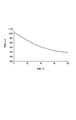
- FIG. It is a figure which shows an example of the temperature characteristic of a thermistor.
- FIG. 3 is a diagram illustrating a configuration example of a voltage doubler rectifier circuit 21.
- FIG. It is a figure which shows the structural example of an environmental information measurement system. It is a figure which shows the structural example of 30 A of environmental information measurement parts. It is a timing chart which shows operation
- the environmental information measuring apparatus shown in the present embodiment is attached to a connection point of feeders (for example, a crimping sleeve for crimping and connecting wires) and has an RFID tag as a communication means. .
- An environmental information collection device (tag reader) installed on the vehicle or the like automatically collects environmental information measured by the environmental information measurement device and performs facility management by performing wireless communication with the environmental information measurement device. It is.
- the environment information measuring device measures temperature will be described. By using the same method as the temperature measurement, it can be applied to the measurement of the temperature of the place where the environmental information measurement device is arranged.
- the environmental information measuring apparatus 1 shown in this embodiment is for temperature management of power transmission lines and distribution lines in a power system (for example, temperature management of connection points of distribution lines and distribution lines) and power supply to train lines. It is used for temperature management of the feeder wire (for example, temperature management of the connection point by a crimping sleeve of the feeder wire).
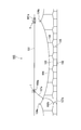
- FIG. 1 is a diagram illustrating an example of a train line on which the environment information measuring device 1 according to the present embodiment is installed.
- the train line 100 includes a feeder 101, a trolley line 102, an auxiliary suspension line 103, a suspension line 104, a hanger 105 that connects the trolley line 102 and the auxiliary suspension line 103, and a feeder branch that connects the feeder 101 and the auxiliary suspension line 103.
- the suspension line 104 is fixed to a power pole (not shown) at the support point 104a.
- One end of the feeder branch portion 107a is fixed to the feeder wire 101 by a clamp 108a, and the other end of the feeder branch portion 107a is fixed to the auxiliary suspension wire 103 by a clamp 108b.
- the environmental information measuring device 1 is attached to the clamp 108a of the feeder branch portion 107a of the feeder 101. Furthermore, the environment information measuring device 1 is attached to a connection point of the feeder 101, for example, a connection location (crimp sleeve 101a) using a crimp sleeve. By mounting in this way, the environmental information measuring device 1 can be provided so as to be thermally coupled to the electric wire that is the object of temperature measurement.
- the clamp 108a of the feeder branch portion 107a and the connection portion (crimp sleeve 101a) of the feeder 101 have contact resistance, and the current passes constantly or discontinuously, so Heat is generated. Also, even if the temperature rise due to the heat generation is not severe, if the temperature continues for a long time, the electrical resistance will increase due to corrosion and fatigue. There is. For this reason, the environmental information measuring device 1 is installed at the feeder branch portion 107a or the connection location 101a of the feeder 101, and the temperature rise at the clamp 108a of the feeder branch portion 107a or the connection location 101a of the feeder 101 is monitored. To do. The environmental information measuring device 1 may be installed at either one of the clamp 108a of the feeder branch portion 107a and the connection location 101a of the feeder 101.
- FIG. 2 is a block diagram showing the configuration of the environmental information measuring apparatus 1 according to the embodiment of the present invention.
- the environmental information measuring apparatus 1 in this figure includes a communication unit 10 that communicates with an environmental information collecting apparatus (tag reader) 51 wirelessly through an antenna 13 and a power source that generates a power supply (DC power supply) from the power of radio waves received by the antenna 13.
- Unit 20 an environment information measuring unit 30 that measures temperature using a thermistor, a time measuring unit 40 that generates temperature measurement data based on a result detected by the environment information measuring unit 30, and the environment information measuring device 1
- the control part 2 which controls the whole and the memory
- the environmental information measuring apparatus 1 includes a communication unit, a CPU, a ROM, and other related IC circuits (integrated circuits), and is a passive type RFID (Radio) that communicates with an external device wirelessly through an antenna 13. This is realized using a Frequency (IDentification) tag.
- the RFID tag is also called an IC tag since it can be realized with a small one-chip IC in recent years.
- the communication unit 10 includes a reception unit 11 and a transmission unit 12.
- the receiving unit 11 receives a radio wave of a predetermined modulation method sent from an external device (environment information collection device 51) through the antenna 13, demodulates the received radio wave, and receives a signal.
- the transmission unit 12 generates a modulated wave based on the temperature measurement data measured by the environment information measurement unit 30, amplifies the modulated wave, and transmits the modulated wave as a radio wave to the external device through the antenna 13.
- the antenna 13 is an antenna formed by a copper foil pattern or the like on the surface of the RFID substrate-like member. For example, the length of the antenna 13 is ⁇ / 4 of the radio transmission frequency. ing.
- the control unit 2 controls the operation of each unit of the environmental information measuring device 1 in an integrated manner.
- the control unit 2 controls temperature measurement in the environment information measurement unit 30 and performs control for wirelessly transmitting temperature measurement data measured by the environment information measurement unit 30 as a signal wave.
- the environmental information measuring device 1 is assigned a unique identification number (sensor ID), and this identification information is stored in the storage unit 3 as RFID identification information.
- the power supply unit 20 is a power supply unit for supplying power to each unit in the RFID tag using radio waves received from the tag reader (receiver) 51 through the antenna 13 as an energy source.
- the power supply unit 20 includes a voltage doubler rectifier circuit 21 and a charge control unit 22.
- the voltage doubler rectifier circuit 21 double rectifies the radio wave received through the antenna 13 to generate a DC voltage and raises the DC voltage to a desired voltage.
- the charging control unit 22 charges a capacitance component such as the capacitor C (33) in the environment information measuring unit 30 with a DC voltage raised to a desired voltage.
- the charge control unit 22 includes a power supply voltage detection unit 22 ⁇ / b> A that detects the magnitude of the power supply voltage generated by the voltage doubler rectifier circuit 21.
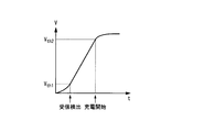
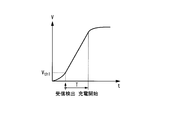
- the power supply voltage detection unit 22A when the voltage of the power generated from the radio wave (power supply voltage) exceeds a predetermined threshold voltage V th1, the environment information collecting device (tag reader) The reception of the radio wave from 51 is detected, and the reception detection information is notified to the control unit 2. Further, as shown in FIG. 5A, the power supply voltage detection unit 22A notifies the control unit 2 of this information when the power supply voltage exceeds a predetermined threshold voltage V th2 (charging start voltage). When the power supply voltage detection unit 22A detects that the power supply voltage has exceeded the threshold voltage V th2 (charge start voltage), the control unit 2 uses the charge control unit 22 to connect the capacitor C (33 in the environment information measurement unit 30). ) Start charging.
- V th2 charging start voltage
- the timing for starting charging the capacitor C is such that, after the power supply voltage exceeds a predetermined threshold voltage V th1 , the control unit 2 counts the predetermined time T with a timer, and the predetermined time T You may make it start charge to the capacitor
- V th1 a predetermined threshold voltage
- V th1 the control unit 2 counts the predetermined time T with a timer, and the predetermined time T You may make it start charge to the capacitor
- FIG. 3A is a diagram illustrating a configuration example of the environment information measuring unit 30 and the time measuring unit 40.
- the environment information measurement unit 30 includes switches SW1 (31) and SW2 (32), a capacitor C (33) charged by the power supply (voltage V cc ) generated by the power supply unit 20,
- the thermistor R SM (34) which is a temperature sensor whose resistance value changes according to temperature, and resistors R 1 (38) and R 2 (39) for dividing the power supply voltage are provided.
- the detection unit 35 is configured by a circuit network including the capacitor C (33) and the thermistor R SM (34). Further, the switches SW1 (31) and SW2 (32) are actually semiconductor switches composed of MOS transistors, analog switches, or the like.
- the timer unit 40 includes a comparator 46, a counter 47, and a reference clock generation circuit 47A. The comparator 46, the counter 47, and the reference clock generation circuit 47A measure (measure) the time from the start of discharging the capacitor C (33) until the charging potential of the capacitor C (33) reaches the reference voltage Vref .
- the switch SW1 (31) has one end connected to the positive terminal of the capacitor C (33) and the other end connected to the positive terminal of the power supply unit (voltage Vcc ) 20 through the power supply line V +.
- the switch SW2 (32) has one end connected to the positive terminal of the capacitor C (33) and the other end connected to the non-inverting input terminal V in (+) of the comparator 46.
- the thermistor R SM (34) serving as the temperature sensor has one end connected to the non-inverting input terminal V in (+) of the comparator 46 and the other end connected to the negative terminal of the power supply unit 20 through the power line V ⁇ . .
- the negative terminal of the capacitor C (33) is connected to the negative terminal of the power supply unit 20 through the power supply line V-.
- Resistor R 1 (38) has one end connected to the power supply line V +, and the other end is connected to one end of the resistor R 2 (39) through the node N1, the other end of the resistor R 2 (39), the power supply line V- It is connected to the. Therefore, the node N1 serves as a resistance voltage dividing point for the output voltage Vcc of the power supply unit 20.
- the node N1 is connected to the inverting input terminal V in ( ⁇ ) of the comparator 46.
- the output side of the comparator 46 is connected to the count control terminal a of the counter 47.
- the clock input terminal b of the counter 47 is connected to the output terminal of the reference clock generation circuit 47A, and the reference clock CLK is input from the reference clock generation circuit 47A to the clock input terminal b.
- the thermistor R SM (34) is arranged so as to be exposed on the mounting surface (mounting surface to the temperature measurement target portion) side of the environment information measuring device 1. Then, the environmental information measuring apparatus 1 is configured such that the thermistor R SM (34) has a silicon rubber compound (electrical insulation and thermal conductivity) at a temperature monitoring target location (for example, the surface of the crimping sleeve 101a to which the feeder 101 is connected). (Silicone rubber compound for enhancing the strength) or silicon grease or the like to fix it. Note that the thermistor R SM (34) may be separated from the main body of the environmental information measuring device 1 so that it can be pulled out via a signal line, and the thermistor R SM alone may be fixed to the temperature monitoring target location.
- a silicon rubber compound electrical insulation and thermal conductivity
- FIG. 3B is a diagram for explaining the operation of the environment information measuring unit 30.
- the operation of the environment information measuring unit 30 will be described with reference to FIGS. 3A and 3B.
- the power supply voltage V cc (charging start voltage) can be supplied from the power supply unit 20 to the environment information measurement unit 30.
- the switch SW1 (31) is closed and the switch SW2 (32) is opened by a control command from the control unit 2, so that the capacitor C (33) is charged to the power supply voltage Vcc (FIG. 3B). state of the time t 0).
- the switch SW1 (31) is opened and the switch SW2 (32) is closed by the control command from the control unit 2, and the charge accumulated in the capacitor C (33) is converted into the thermistor R SM ( 34) to discharge.
- Charging voltage of the capacitor C (33) decreases gradually, at time t 1, equal to the reference voltage V ref.
- the output signal V out of the comparator 46 changes from the H state (potential corresponding to the power supply voltage V + to the comparator) to the L state (to the comparator). Inverted to the power supply voltage V-potential.
- the counter 47 is controlled by the reference clock generation circuit 47A during the time t d from the start of discharging of the capacitor C (33) until the output signal of the comparator 46 transitions from the H state to the L state according to a control command from the control unit 2.
- the output reference clock CLK is counted.
- the environment information measuring unit 30 measures the temperature by converting the time into the time by counting the time (the number of reference clocks) from the start of the discharge of the capacitor C (33) until the comparator 46 operates.
- the resistance value of the thermistor R SM (34) decreases as the temperature rises. Therefore, as the temperature rises, the discharge rate of the charge of the capacitor C (33) increases, and the number of reference clocks counted by the counter 47 decreases. Thus, based on the number of reference clocks counted by the counter 47, the temperature of the thermistor R SM (34) (that is, the temperature of the temperature measurement target portion) can be measured.
- the circuit configuration of the environment information measuring unit 30 shown in FIG. 3A is adopted and the mathematical formulas shown in FIG. 3B will be described later.
- FIG. 4 is a diagram for explaining the overall operation of the environment information measuring apparatus 1.
- the environment information collection device (tag reader) 51 gradually approaches the environment information measurement device (RFID tag) 1 from a distance
- the environment information collection device (tag reader) 51 and the environment information measurement device (RFID tag) 1 Shows an example in which the environmental information collection device 51 receives temperature data from the environmental information measurement device 1 in a state in which the distances are close to each other.
- the operation of the environment information measuring apparatus 1 will be described with reference to FIG.
- the tag reader (environment information collection device) 51 approaches the environment information measurement device 1 while transmitting a signal requesting transmission of temperature information to the environment information measurement device (RFID tag) 1 by radio waves (step S11). .
- the environmental information measuring device 1 receives the radio wave transmitted from the environmental information collecting device 51 (step S21), and the power supply unit 20 generates a power source (DC power source) from the electric power obtained from the received radio wave.
- the voltage of the power source increases as the environmental information collection device 51 approaches the environmental information measurement device 1.
- the generated power supply voltage is detected by the power supply voltage detection unit 22A (step S22), and when it is detected that the voltage exceeds a predetermined threshold voltage Vth1 as shown in FIG.
- the control unit 2 is notified that the radio wave from the information collecting device 51 has been received and detected. Thereafter, when the power supply voltage increases and it is detected that the power supply voltage is equal to or higher than the predetermined threshold voltage Vth2 as shown in FIG. 5A (when it is detected that the charging start voltage has been reached), this is controlled. Notify part 2.
- the control unit 2 detects that the power supply voltage is equal to or higher than the predetermined threshold voltage Vth2 , the switch SW1 (31) in the environmental information measurement unit 30 is closed and the switch SW2 (32) is opened. Thus, the capacitor C (33) is charged with the power supply voltage (step S23). Then, after a predetermined time has elapsed, that is, after the charging of the capacitor C (33) is completed, the control unit 2 opens the switch SW1 (31) in the environmental information measurement unit 30 and closes the switch SW2 (32). As a result, discharging of the electric charge charged in the capacitor C (33) is started through the thermistor R SM (34) (step S24).
- the control unit 2 starts discharging the capacitor C (33), starts the counter 47, and starts counting the reference clock CLK by the counter 47 (step S25). Then, the comparator 46 detects whether or not the potential of the capacitor C (33) has become equal to or lower than the reference voltage Vref as the capacitor C (33) is discharged (step S26). When it is detected that the charging potential of the capacitor C (33) has become equal to or lower than the reference voltage Vref (step S26: Yes), the control unit 2 stops the counting operation of the counter 47 and counters the counter 47. Is sent to the environmental information collection device 51 as temperature measurement data converted into time (step S27).
- the environmental information collection device 51 receives temperature measurement data from the environmental information measurement device 1 (step S12), stores this temperature data, and displays it on a display device or the like. According to the above procedure, the environment information measuring device 1 measures the temperature of the temperature measurement target portion, and the environment information collecting device (tag reader) 51 can automatically collect the temperature measurement data measured by the environment information measuring device 1. it can. For this reason, temperature measurement data can be easily and automatically collected even when there are many temperature measurement target locations.
- the environment information measuring unit 30 includes the switches SW1 (31) and SW2 (32), the capacitor C (33), the thermistor R SM (34), and the resistors R 1 (38) and R 2 (39).
- the timer unit 40 includes a comparator 46, a counter 47, and a reference clock generation circuit 47A.
- the environmental information measuring apparatus 1 measures the temperature by converting the temperature into time by combining the environmental information measuring unit 30 and the time measuring unit 40.
- the reason for this circuit configuration is that the environmental information measuring apparatus 1 uses an RFID tag, and this RFID tag generates a power source based on radio waves received from a tag reader, and thus a low power consumption circuit. This is because it is required. Hereinafter, this point will be described.
- thermocouples There are several types of temperature sensors, and they are classified into thermocouples, PN junction diodes, infrared types, thermistors, and the like when classified by operating principle.
- the thermocouple uses a current that flows when different kinds of metals are joined in a ring shape and the hot beds of the two contacts are different. In this method, it is necessary to install one of the contacts as a measurement target and the other contact at a place where the temperature is known, which is not suitable for use in the RFID tag as a target in the present invention.
- the method using a PN junction diode utilizes the temperature dependence of the forward voltage drop of the diode, and a silicon diode in an IC or LSI can be used as it is as a temperature sensor, but its sensitivity is 1 mV /
- the current flowing through the diode needs to be constant, and handling is difficult.
- the infrared type detects the amount of infrared rays emitted from an object, but is not suitable for incorporation in an RFID tag in terms of size and power consumption.
- the thermistor is a resistance using a material whose resistivity changes with temperature.
- NTC Negative Temperature Coefficient
- the coefficient of change in resistivity with respect to temperature has a negative value is often used because it has a relatively good linearity as compared with that in which the coefficient of change shows a positive value.
- a highly accurate thing can be manufactured and it is possible to measure temperature with desired precision. Further, if the resistance value is up to about 100 k ⁇ , the manufacture is easy.
- FIG. 3B shows an example of the temperature characteristic of the thermistor.
- the power consumption of this thermistor is 12.5 ⁇ W (2.5 V ⁇ 5 ⁇ A), which is a low power consumption. is there.
- AD analog / digital
- Many AD converters use a comparator that compares the voltages of two input signals and outputs the result as a digital signal.
- the power consumption of an AD converter is very large for use in an RFID tag, and even a low power consumption type AD converter is about several hundred ⁇ W. For this reason, it is difficult to incorporate the AD converter in the RFID tag.
- the signal output from the AD converter is a serial or parallel digital signal, but considering the information required in this embodiment, it is not always necessary to convert an analog signal into a digital signal. Therefore, temperature measurement data is obtained as a digital quantity obtained by converting temperature into time by using an RC discharge circuit, a comparator, and a counter. That is, the circuit configuration shown in FIG. 3A is adopted.
- the switch SW1 (31) is closed, the switch SW2 (32) is opened, and the capacitor C (33) is charged with the power supply voltage Vcc .
- the control unit 2 switches the switch SW1 (31) to open and the switch SW2 (32) to close to discharge the charge of the capacitor C (33) through the thermistor RSM (34).
- the time until the voltage of the capacitor C (33) becomes equal to or lower than the reference voltage Vref is measured.
- the reference voltage V ref is generated by dividing the power supply voltage V cc using the resistors R 1 (38) and R 2 (39)
- the discharge time from the start of discharge until reaching the reference voltage V ref is the power supply voltage. It becomes irrelevant to the magnitude of the voltage. That is, the discharge voltage V in (t) is expressed as Expression (1).
- the discharge voltage V in (t) shown in the equation (1) is expressed as a first-order response function by the power supply voltage V cc and the time constant (R SM C). Further, the reference voltage V ref is expressed as an equation (2) from the resistors R 1 (38) and R 2 (39).
- ⁇ represents a partial pressure ratio.
- the time t d can be represented by the capacitance C and the voltage division ratio of the resistance value R SM and capacitors thermistor, it is understood that it does not rely on the power source voltage V cc. Therefore, by using this circuit, the measured temperature can be converted into time. Furthermore, it is also possible to directly use a signal output from this circuit as a response signal from the RFID tag (environmental information measuring device 1) to the tag reader (environmental information collecting device 51). For example, temperature measurement is started at the same time when the RFID tag starts returning data to the tag reader. That is, the controller 2 switches the switches SW1 (31) and SW2 (32) to start discharging the capacitor C (33).
- the RFID tag transmits, for example, “0” until the discharge voltage V in (t) reaches the reference voltage V ref and the output of the comparator is inverted, and “1” after the output of the comparator is inverted.
- the tag reader can calculate the temperature measured by the RFID tag by demodulating the data from the RFID tag and counting the number of “0” contained in the data.
- the environmental information measuring unit 30 operates with a low power supply voltage and uses a low power consumption type analog switch element.
- Currently available products include, for example, specifications of “operable power supply voltage range: 1.8 V to 5.5 V”, “power consumption: 1 ⁇ W”, and “operating frequency band: 250 MHz”. If the above analog switch and resistors R 1 (38) and R 2 (39) are used with a resistance of several M ⁇ , the power consumption of this circuit can be suppressed to about 1 ⁇ W.
- the environment information measuring apparatus 1 according to the present embodiment is required to have a low power consumption and a simple circuit configuration because communication is performed using an RFID tag. Therefore, the environment information measuring unit 30 has a circuit configuration as shown in FIG.
- the capacitor C (33) is charged in advance, and a change in voltage when discharging from the capacitor C (33) is detected.
- the power supply of the environmental information measuring device 1 is supplied from the power supply unit 20 that generates power based on the received radio wave by the RFID tag. Therefore, unlike a normal power supply, the power supply is an unstable power supply that varies depending on the received electric field strength of the received radio wave. If a change in voltage when the capacitor C (33) is charged is detected, the power supply voltage changes due to a change in the received electric field strength of the radio wave, and the charging voltage is not stable. May cause errors. Therefore, in this embodiment, the measurement accuracy is improved by using the voltage at the time of discharging from the capacitor C (33).
- FIG. 7 is a diagram illustrating a configuration example of the voltage doubler rectifier circuit 21.
- the voltage doubler rectifier circuit 21 shown in FIG. 7 is a circuit composed of a Cockcroft-Walton circuit (hereinafter abbreviated as “CW circuit”) in which booster rectifier circuits in which diodes and capacitors are combined are stacked in multiple stages. It is a configuration.
- This voltage doubler rectifier circuit 21 is an example in which the input impedance of an antenna is connected to a symmetrical three-stage CW circuit.
- a short stub is used to match the antenna and the circuit. Since the short stub takes positive and negative reactance values depending on its length, the length is actually changed so that the load voltage is maximized.
- a half-wave diball antenna or a meander antenna can be used as the antenna.
- FIG. 8 is a diagram illustrating a configuration example of a temperature measurement system including the environment information measurement device 1 and the environment information collection device 51 according to the present invention.
- the environment information measuring device 1 (1A, 1B, 1C) is connected to each temperature measurement target portion (connection point of feeders) of a plurality of feeders 101 (101A, 101B, and 101C) connected in series along the track.
- the environmental information collection device (tag reader) 51 is installed in a train 50 that runs on the track.
- the environment information collecting device 51 is equipped with a tag reader function for communicating with the environment information measuring device (RFID tag) 1 using a radio signal from the RFID system.
- the environmental information collection device 51 includes an antenna 52, a display unit 53, and an operation switch group 54.
- the display unit 53 is a liquid crystal display or the like.
- the operation switch group 54 includes push button button type switches and the like.
- Each environmental information measuring device 1 (1A, 1B, 1C) receives radio waves of radio signals transmitted from the environmental information collecting device 51 when the train 50 moves and the environmental information collecting device 51 approaches. Then, the environmental information measuring device 1 (1A, 1B, 1C) that has received the radio wave from the environmental information collecting device 51 generates a power source (DC power source) from the power obtained from the received radio wave by the power source unit 20. . Each environmental information measuring device 1 is activated by the generated power supply. The activated environment information measuring device 1 measures the temperature of the feeder 101 and transmits the measured temperature measurement data to the environment information collecting device 51 together with identification ID information (RFID identification information).
- RFID identification information identification information
- the environmental information collection device 51 and the environmental information measurement device 1A approach each other, and the environmental information collection device 51 receives temperature measurement data from the environmental information measurement device 1A.
- the environmental information collection device 51 and the environmental information measurement device 1B approach, and the environmental information collection device 51 receives temperature measurement data from the environmental information measurement device 1B.
- the environmental information collection device 51 and the environmental information measurement device 1C approach, and the environmental information collection device 51 receives temperature measurement data from the environmental information measurement device 1C.
- This temperature measurement data is displayed as a numerical table, a graph or the like, and it is determined whether or not the temperature of the temperature measurement target portion is in the normal range. In addition, an alarm signal can be generated based on the determination result, which can be used for countermeasures against abnormalities.
- Each temperature measurement data received by the environment information collection device 51 is stored as temperature elapsed data together with the identification ID information of the environment information measurement device 1 and the measurement date / time information.
- each environmental information measuring device 1 (1A, 1B, 1C) can be obtained by simply bringing the environmental information collecting device 51 close to each environmental information measuring device 1 (1A, 1B, 1C). Temperature measurement data can be automatically collected from For this reason, it is possible to easily determine whether or not the connection point of the feeder 101 is good even when there are many temperature measurement target portions.
- the reference numeral 34 is described as the thermistor R SM .
- the strain gauge has a structure in which a thin resistor is mounted on a resilient insulator. When the insulator is deformed, the resistor expands and contracts, and its resistance value changes. By replacing this with a thermistor of a temperature sensor, strain, displacement, and load can be measured.
- a strain gauge to the atmospheric pressure sensor.
- a metal sealed container whose inside is evacuated contracts according to the magnitude of the atmospheric pressure, and the amount of displacement is detected by the strain gauge.
- the thermistor of the temperature sensor circuit By replacing this with the thermistor of the temperature sensor circuit, an atmospheric pressure sensor can be obtained. With such a configuration, it is possible to detect the atmospheric pressure.
- the capacitance of the capacitor can be changed according to the atmospheric pressure by causing the electrode on one side of the capacitor to be displaced by the atmospheric pressure.
- the atmospheric pressure can be measured by applying such a capacitor to the capacitor 33 in the detection unit 35.
- the reference numeral 33 is described as a capacitor C having a fixed capacitance
- the reference numeral 34 is a thermistor R SM.
- the humidity sensor has a capacitor structure formed by electrodes provided with a dielectric whose capacitance changes depending on humidity.
- the humidity sensor was replaced with a capacitor C that has been used in a temperature sensor circuit in the environment information measuring apparatus 1, by replacing the usual resistance in place of the thermistor R SM, the environmental information measurement device 1, detecting humidity Can do.
- a polymer is used as the dielectric forming the humidity sensor.
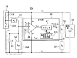
- FIG. 9A is a diagram illustrating a configuration example of the environment information measurement unit 30A. As shown in FIG.
- the environment information measuring unit 30A includes switches SW1 (31A) and SW2 (32A), a capacitor C (33) charged by the power source (voltage V cc ) generated by the power source unit 20, A thermistor R SM (34) which is a temperature sensor whose resistance value changes according to temperature, a resistor R 3 (37), and resistors R 1 (38) and R 2 (39) for dividing a power supply voltage are provided.
- the detection unit 35A is configured by a circuit network including the capacitor C (33), the thermistor R SM (34), and the resistor R 3 (37). Further, a switch unit 36 including the switch SW1 (31A) and the switch SW2 (32A) is configured.
- the switch unit 36 is actually a semiconductor switch composed of a MOS transistor or the like, or may be a CMOS digital circuit.
- a CMOS digital circuit is an inverter circuit.
- Such a switch unit 36 can be regarded as a changeover switch that outputs a high level signal or a low level signal.
- the switch unit 36 outputs a signal of a high (high) level and a low (low) level. One of the signals is output.
- the switch section 36 has an output terminal connected to the resistor R 3 (37), a power supply terminal connected to the positive terminal of the power supply section (voltage V cc ) 20 through the power supply line V +, and a ground terminal connected to the power supply line. It is connected to the negative terminal of the power supply unit (voltage V cc ) 20 through V ⁇ .
- the other end of the resistor R 3 (37) connected to the switch unit 36 is connected to the positive terminal of the capacitor C (33) and the non-inverting input terminal V in (+) of the comparator 46.
- the thermistor R SM (34) serving as the temperature sensor has one end connected to the non-inverting input terminal V in (+) of the comparator 46 and the other end connected to the negative terminal of the power supply unit 20 through the power line V ⁇ . .
- the negative terminal of the capacitor C (33) is connected to the negative terminal of the power supply unit 20 through the power supply line V-.
- Resistor R 1 (38) has one end connected to the power supply line V +, and the other end is connected to one end of the resistor R 2 (39) through the node N1, the other end of the resistor R 2 (39), the power supply line V- It is connected to the. Therefore, the node N1 serves as a resistance voltage dividing point for the output voltage Vcc of the power supply unit 20.
- the node N1 is connected to the inverting input terminal V in ( ⁇ ) of the comparator 46.
- the output side of the comparator 46 is connected to the count control terminal a of the counter 47.
- the clock input terminal b of the counter 47 is connected to the output terminal of the reference clock generation circuit 47A, and the reference clock CLK is input from the reference clock generation circuit 47A to the clock input terminal b.
- the switch part 36 switches the voltage output to an output terminal according to the control command supplied from the control part 2 (FIG. 1).
- FIG. 9B is a timing chart showing the operation of the environment information measuring unit 30A.
- the vertical axis indicates the voltage of each signal, and the horizontal axis indicates the passage of time.
- the control unit an input pulse supplying switch section 36 is in the detection section 35A in response to a control command from 2 V in, potential V c of the capacitor C (33), a power supply and a fixed resistor
- the reference potential generated by (resistors R 1 and R 2 ) is V ref and the output of the comparator 46 is V out .
- T d is the time during which the comparator outputs a low level, that is, the time when V c > V ref .
- V cc charging start voltage
- the switch unit 36 In this initial state, the switch unit 36 outputs a high level signal in response to a control command from the control unit 2. That is, the switch unit 36, and switches SW1 to (31A) to the closed, by the switch SW2 (32A) is opened, to start charging of the capacitor C (33) (at time t 0 in FIG. 9B state). By maintaining this charged state, electric charge is gradually accumulated in the capacitor C (33), and charging via the resistor R 3 (37) proceeds. Charging voltage of the capacitor C (33) gradually increases, at time t 1, equal to the reference voltage V ref.
- the switch unit 36 When the charging voltage of the capacitor C (33) becomes equal to or higher than the reference voltage V ref , the output signal V out of the comparator 46 changes from the L state (the potential corresponding to the power supply voltage V ⁇ to the comparator) to the H state (to the comparator). To the power supply voltage V +).
- the switch unit 36 outputs the low level signal (the state at time t 2 in FIG. 9B). That is, in the switch unit 36, the switch SW1 (31A) is opened and the switch SW2 (32A) is closed, so that the charge accumulated in the capacitor C (33) is discharged through the thermistor R SM (34).
- Charging voltage of the capacitor C (33) decreases gradually, at time t 3, equal to the reference voltage V ref.
- the output signal V out of the comparator 46 changes from the H state (potential corresponding to the power supply voltage V + to the comparator) to the L state (to the comparator). Inverted to the power supply voltage V-potential.
- the counter 47 In parallel with the charge / discharge control, the counter 47 counts the reference clock CLK output from the reference clock generation circuit 47A according to a control command from the control unit 2.
- the counter 47 starts charging the capacitor C (33) at a time t d1 from the start of charging of the capacitor C (33) (time t 0 ) to time t 1 when the output signal of the comparator 46 transitions from the H state to the L state.
- time t 0) starts to discharge from (time t 2) is up to the time t on, the time t the output signal of the discharge start (time t 2) from the comparator 46 of the capacitor C (33) transitions from the L state to H state Measured for time t d2 up to 3 .
- the environment information measuring unit 30A counts the time (reference clock number) during which the output state of the comparator 46 indicates the L state in accordance with the control command from the control unit 2 and the output state of the comparator 46.
- the temperature is converted into time and measured.
- the environment information measuring unit 30A converts the information into time information based on the detected temperature.
- the environment information measuring unit 30A can directly use the converted information for a return signal from the RFID tag to the tag reader. If it is assumed that the reference potential is generated by dividing the power supply voltage by a resistor, the result determined by the comparator does not change depending on the fluctuation of the power supply voltage.
- LPV7215 (trademark) manufactured by National Semiconductor is used as the comparator 46 of the experimental circuit. This comparator has an extremely small power consumption of 1.2 ⁇ W (microwatts) when operated at a power supply voltage of 2 V (volts), and can contribute to a reduction in power consumption of the environmental information measuring unit 30A (sensor circuit).
- the detection unit 35A can simplify the description of the response characteristics by using different operation models when the capacitor C (33) is charged and discharged.
- 10A and 10B are diagrams illustrating an operation model of the detection unit 35A when the detection unit 35A is shown as an equivalent circuit. Initially, with reference to FIG. 10A, the operation
- an input signal (input pulse) supplied from the switch unit 36 is at a high level according to a control command from the control unit 2, if this is regarded as a power supply, the circuit connected to the non-inverting input terminal of the comparator 46 is The circuit shown in FIG. 10A can be converted.
- the time t d can be expressed as Expression (8).
- the theoretical value of the time t d can be calculated based on the equations (5), (7), and (8).
- FIG. 11 is a diagram illustrating a result calculated for each temperature.
- the vertical axis of FIG. 11 shows the time t d
- the horizontal axis shows the temperature.
- the value of the time t d decreases monotonously as the temperature increases, and it is shown that the temperature and the value of the time t d have a one-to-one correspondence.
- FIG. 12 is a diagram comparing the actual measured value and the theoretical value of the temperature measured using the environment information measuring unit 30A.
- the vertical axis of FIG. 12 shows the time t d, the horizontal axis shows the temperature.
- the experimental value of measurement temperature marked with “x” in the figure
- the theoretical value graph indicated by a solid line in the figure
- this environmental information measuring unit 30A The configuration shows that the temperature can be measured.
- the power consumption can be reduced to a total power consumption of 8 W (watts).
- the environmental information measuring device corresponds to the environmental information measuring device 1.
- the communication unit in the present invention corresponds to the communication unit 10, and the power supply unit in the present invention corresponds to the power supply unit 20.
- the environment information detection unit in the present invention corresponds to the detection units 35 and 35A (having the thermistor R SM (34) and the capacitor C (33)), and the time measurement unit in the present invention is the time measurement unit 40 (the comparator 46 and Corresponding to the counter 47).
- the first switch in the present invention corresponds to the switch SW1 (31), and the second switch in the present invention corresponds to the switch SW2 (32).
- the environmental information in the present invention corresponds to the temperature measurement data of the temperature measurement target portion measured by the environmental information measuring device 1.
- the environmental information measuring device 1 includes the power supply unit 20, the environmental information detection unit 30, the time measuring unit (such as the comparator 46 and the counter 47) 40, and the control unit 2. And comprising.
- the power supply unit 20 generates a power supply voltage to be supplied to the load from the received radio wave power.
- the load includes the environment information detection unit 30, the time measuring unit 40, and the control unit 2.
- the environment information detection unit 30 includes a detection unit 35 including a circuit element whose impedance or capacitance changes according to a physical quantity detected under the environment of a measurement target location, and changes according to the response characteristic of the detection unit 35. Output a signal.
- the timer 40 measures the time until the voltage of the output signal reaches a predetermined detection voltage from the start of measurement, and generates environment information corresponding to the physical quantity based on the time.
- the control unit 2 controls the operation of the environment information detection unit 30.
- environmental information of the measurement target location for example, temperature (temperature of a transmission line or distribution line in a power system, or a connection point of a feeder line in a train line), humidity or atmospheric pressure can be reduced with low power consumption and a simple circuit configuration. Easy to measure.
- the environment information measuring device 1 is provided with the communication part 10 which transmits the measurement data produced
- measurement data generated based on the environment information measured by the environment information detection unit 30 (for example, temperature measurement data measured by converting temperature into time more precisely).
- an external device for example, environment information collection device
- environmental information of the measurement target location for example, temperature (temperature of a transmission line or distribution line in a power system, or a connection point of a feeder line in a train line), humidity or atmospheric pressure can be reduced with low power consumption and a simple circuit configuration.
- the detection unit 35 includes a capacity
- the control unit 2 charges the capacity included in the detection unit 35 according to the generated power supply voltage, and the time by the time measuring unit 40.
- the control unit 2 charges the capacitor (capacitor C) included in the detection unit 35 when the generated power supply voltage reaches a predetermined voltage (charging start voltage). Thereafter, discharging of the capacity (capacitor C) included in the detection unit 35 is started, and in the time measuring unit 40, the charging potential of the capacity (capacitor C) included in the detection unit 35 is reduced to a predetermined reference value Vref . Measure the time to complete. Thereby, it becomes possible to measure by converting the environment information of the measurement target portion into time using the CR discharge circuit. Therefore, temperature measurement can be performed with low power consumption and a simple circuit.
- the control unit 2 starts charging the charging unit (capacitor C) when the generated power supply voltage reaches a predetermined charging start voltage.
- the capacitor (capacitor C) included in the detection unit is charged, and then the detection is performed.
- the capacitor (capacitor C) included in the unit 35 starts discharging. Thereby, it becomes possible to measure by converting the environment information of the measurement target portion into time using the CR discharge circuit. Therefore, environmental information can be measured with a low power consumption and a simple circuit.
- the time measuring part 40 is the time until the voltage of the said signal falls to the said detection voltage after starting discharge from the capacity
- the capacitor (capacitor C) included in the detection unit is charged, and then Discharging of the capacitance (capacitor C) included in the detection unit is started, and the time measuring unit 40 measures the time until the charging potential of the environmental information (capacitor C) is reduced to a predetermined reference voltage Vref .
- Vref a predetermined reference voltage
- the environment information detection part 30 is switch SW1 (31) which interrupts
- the control unit 2 charges the capacitor (capacitor C) from the power supply unit 20 with the switch SW1 (31) connected, and opens the switch SW2 (32). The discharge from the capacitor (capacitor C) is stopped.
- the control unit 2 opens the switch SW1 (31) to stop the charging from the power source unit 20 to the capacitor (capacitor C), and switches the switch SW2 (32).
- the capacitor (capacitor C) is discharged in the connected state.
- the switch SW1 (31) cuts off the capacitance (capacitor C) and the temperature detection unit (thermistor R SM ).
- the switch SW1 (31) When discharging the capacity (capacitor C), the switch SW1 (31) cuts off the power supply unit 20 and the capacity (capacitor C), and the switch SW2 (32) detects the capacity (capacitor C) and temperature. Connected to the unit (thermistor R SM ). Thus, the control unit 2 controls the switch SW1 (31) and the switch SW2 (32) to easily perform charging of the capacitor (capacitor C) and discharging by the temperature detection unit (thermistor R SM ). Can do. For this reason, it is possible to measure the environment information of the measurement target portion by converting it into time with low power consumption and a simple circuit configuration.
- a connection state and an open state are kept mutually complementary between switch SW1 (31) and switch SW2 (32).
- a single SPDT (Single Pole Double Throw) switch can be obtained by combining the switch SW1 (31) and the switch SW2 (32).
- the switch SW1 (31) and the switch SW2 (32) can function as SPDT switches to select and output either the power supply voltage or the reference potential.
- Such a switch can be replaced with a digital circuit element (semiconductor device) having a CMOS structure.
- control unit 2 controls the switch SW1 (31) and the switch SW2 (32) to easily perform charging of the capacitor (capacitor C) and discharging by the temperature detection unit (thermistor R SM ). Can do. For this reason, the configuration of the switch SW1 (31) and the switch SW2 (32) can be further simplified, and the environment information of the measurement target portion is converted to time and measured with low power consumption and a simple circuit configuration. Can do.
- the physical quantity is any one of temperature, atmospheric pressure, and humidity
- the environmental information detection unit 30 detects the physical quantity using a circuit element provided in the detection unit 35.
- the environment information detection unit 30 that detects any one of temperature, atmospheric pressure, and humidity in the environment can be configured in accordance with the circuit element provided in the detection unit 35.
- the temperature can be detected by providing a temperature detection unit (thermistor R SM )
- the humidity can be detected by providing the humidity detection unit
- by providing the atmospheric pressure sensor Barometric pressure can be detected.
- the environmental information detection part 30 is provided so that it may couple
- the temperature detection unit (thermistor R SM ) is disposed so as to contact the surface of the temperature measurement target portion.
- the contact is made through a silicon rubber compound or the like. Thereby, the temperature of a temperature measurement object location can be measured correctly.
- the environmental information measurement system includes the environmental information measurement device that transmits information measured based on the detected environmental information, and the environmental information collection device that collects the transmitted information.
- the environmental information collection device 51 collects and stores measurement data transmitted from the environmental information measurement device 1.
- the temperature of the object to be measured for example, the temperature of the power transmission line and distribution line in the power system, or the feeder line in the train line can be easily measured with a low power consumption circuit.
- temperature data can be measured easily and automatically.
- the environmental information measuring device 1 mentioned above is comprised using the RFID tag, and has a computer system inside.
- the process of each unit described above is stored in a computer-readable recording medium (ROM or the like) in the form of a program, and the above process is performed by the computer reading and executing the program.
- ROM computer-readable recording medium
- the environment information measuring device and environment information measuring system of this invention are not limited only to the above-mentioned illustration example, In the range which does not deviate from the summary of this invention.
- the aspect of Embodiment 2 or 3 can be applied to the aspect shown in Embodiment 4.
- the object of measurement is temperature measurement, and it becomes easy to perform various environmental information measurements.
- the case where the deviation by the structure of an environmental information measuring device etc. arises is assumed. By specifying in advance the deviation that occurs depending on the configuration of the environmental information measuring device, the deviation information can be corrected.
- the environmental information collection device stores the deviation information in a storage unit provided in the environmental information collection device in advance, and refers to the deviation information stored in the storage unit according to the measurement result notified from the environmental information measurement device. Thus, the measurement result notified from the environment information measuring device can be corrected.
- the present invention can be used for an apparatus, a system, a method, and the like that manage environmental information such as temperature, humidity, and atmospheric pressure at connection points of a power transmission line, a distribution line, a feeder line, and the like.
Landscapes
- Physics & Mathematics (AREA)
- General Physics & Mathematics (AREA)
- Engineering & Computer Science (AREA)
- Computer Networks & Wireless Communication (AREA)
- Nonlinear Science (AREA)
- Arrangements For Transmission Of Measured Signals (AREA)
- Measuring Temperature Or Quantity Of Heat (AREA)
- Testing Or Calibration Of Command Recording Devices (AREA)
- Selective Calling Equipment (AREA)
Abstract
環境情報計測装置は、電源部と、環境情報検出部と、計時部と、制御部とを備える。電源部は、受信した電波から、負荷に供給する電源電圧を生成する。負荷は、環境情報検出部、計時部、及び制御部を含む。環境情報検出部は、測定対象箇所の環境下で検出される物理量に応じてインピーダンスまたは静電容量が変化する回路素子を備える検出部を有し、検出部の応答特性に応じて変化する信号を出力する。計時部は、出力された信号の電圧が、計測開始から予め定められる検知電圧に達するまでの時間を計測し、当該時間に基づいて、前記物理量に応じた環境情報を生成する。制御部は、環境情報検出部の動作を制御する。
Description
本発明は、被測定対象箇所の環境情報を測定することができる、環境情報計測装置、環境情報計測システム、及び環境情報計測方法に関する。
本願は、2010年9月16日に、日本に出願された特願2010-208452号に基づき優先権を主張し、その内容をここに援用する。
本願は、2010年9月16日に、日本に出願された特願2010-208452号に基づき優先権を主張し、その内容をここに援用する。
広範囲に分散した測定対象箇所ごとの環境情報をそれぞれ測定することが必要とされる場合がある。測定される環境情報には、温度、湿度、気圧などの情報があり、環境情報計測装置がそれらの情報を測定する。測定する情報に対応できる様々な測定方法が知られている。例えば、温度を測定する場合では、被測定対象の温度を非接触で測定する方法としては、赤外線カメラを用いる方法が知られている(非特許文献1を参照)。また、被計測対象に接触して計測する方法には、示温ラベルを用いる方法がある。示温ラベルを用いる方法は、目視で表示色を検出することが必要とされ、示温ラベルを確認できる位置まで測定者が接近して観測している。これらの被測定対象の温度を測定する方法は、間接的な測定であるが気温を測定する方法として用いることができる。
ただし、上記のような方法では、測定者による作業が必要になることから、測定対象箇所、測定頻度が多くなる用途や、測定者が接近できない場所の測定には適さない場合がある。そこで、被計測対象に温度センサを接触させて計測する記録装置が開示されている(特許文献1参照)。
浜松フォトニクス株式会社、"近赤外~赤外用カメラ/画像計測装置"、[online]、平成22年7月、[平成22年7月28日検索]、インターネット<URL:http://jp.hamamatsu.com/products/camera/0001/index_ja.html>
ところで、電力系統における送電線や配電線の温度管理(例えば、送電線や配電線等の接続点の温度管理)や、電車線へ電力を供給するためのき電線の温度管理(例えば、き電線の接続点の温度管理)を行うことが求められている。測定対象箇所は、広範囲に分散しており、繰り返して測定することが必要とされ測定頻度の要求も高い。
非特許文献1に示されるような赤外線カメラを用いる方法では、測定箇所と被計測対象との間の距離を置いて計測することができる。赤外線カメラを測定箇所ごとに定点設置する場合では、必要とされる設備規模が大きくなり実現困難である。また、赤外線カメラを測定箇所に移動させて測定する場合では、連続的な測定ができなくなり、測定者が、被計測対象に赤外カメラを向けて計測することが必要とされることから、測定箇所ごとの計測時間も長くなる。
また、示温ラベルを用いる方法は、目視で表示色を確認できる位置まで測定者が接近して観測することが必要とされることから、充電状態の電線の温度計測には、安全上の理由で適用条件が制限される場合がある。
そこで、特許文献1に記載の記録装置を用いることにより、測定者の作業量を低減させるとともに、安全に測定を行うことができる。
また、示温ラベルを用いる方法は、目視で表示色を確認できる位置まで測定者が接近して観測することが必要とされることから、充電状態の電線の温度計測には、安全上の理由で適用条件が制限される場合がある。
そこで、特許文献1に記載の記録装置を用いることにより、測定者の作業量を低減させるとともに、安全に測定を行うことができる。
しかしながら、被測定対象箇所(温度測定対象箇所)がさらに増大する場合や、あるいは測定頻度をさらに高めることが必要となる場合がある。このような要求に応じるために、記録した測定データを通信する時間が長くなり、また、環境情報計測装置の消費電力が増加し、大規模な装置が必要となるなど実現が困難な場合が生じる。上記は、温度計測の場合を示したものであるが、被測定対象箇所の環境情報を収集する場合においても同様の問題が生じる。つまり、気温、湿度や気圧などの環境情報を収集する被測定対象箇所(温度測定対象箇所)が多い場合や、あるいは測定頻度が高い場合には、上記のように温度を計測することが困難であるのと同様に実現が困難な場合が生じる。また、気温以外の測定項目の環境情報(湿度、気圧など)の測定においても、同様に実現が困難な場合が生じるという問題がある。
本発明は、斯かる実情に鑑みてなされたものであり、本発明の目的は、被測定対象箇所の環境情報を測定でき、かつ、低消費電力な環境情報計測装置、環境情報計測システム及び環境情報計測方法を提供することにある。
本発明は、上記課題を解決するためになされたものであり、本発明の一実施形態に係る環境情報計測装置は、電源部と、環境情報検出部と、計時部と、制御部とを備える。前記電源部は、受信した電波から、負荷に供給する電源電力を生成する。負荷は、前記環境情報検出部、前記計時部、及び前記制御部を含む。前記環境情報検出部は、測定対象箇所の環境下で検出される物理量に応じてインピーダンスまたは静電容量が変化する回路素子を備える検出部を有し、前記検出部の応答特性に応じて変化する信号を出力する。前記計時部は、前記信号の電圧が、計測開始から予め定められる検知電圧に達するまでの時間を計測し、当該時間に基づいて前記物理量に応じた環境情報を生成する。前記制御部は、前記環境情報検出部の動作を制御する。
前記環境情報計測装置は、前記環境情報を要求に応じて送信する通信部を備えてもよい。
前記検出部は容量を含み、前記制御部は、前記電源電圧に応じて、前記容量への充電と、前記計時部による時間の計測とを制御してもよい。
前記制御部は、前記電源電圧が、予め定められた充電開始電圧に達した時に、前記容量への充電を開始させてもよい。
前記計時部は、前記容量からの放電を開始してから、前記信号の電圧が前記検知電圧に低下するまでの時間を計測してもよい。
前記環境情報検出部が、前記電源部から前記容量への充電を遮断する第1のスイッチと、前記容量からの放電を遮断する第2のスイッチと、を備えてもよい。前記制御部は、前記容量に充電する場合に、前記第1のスイッチを接続状態にして前記電源部から前記容量への充電を行い、前記第2のスイッチを開放状態にして前記容量からの放電を停止してもよい。また、前記制御部は、前記容量から放電する場合に、前記第1のスイッチを開放状態にして前記電源部から前記容量への充電を停止し、前記第2のスイッチを接続状態にして前記容量から放電してもよい。
前記環境情報計測装置において、前記第1のスイッチと前記第2のスイッチの間で接続状態と開放状態が互いに相補の関係に保たれていてもよい。
前記計時部が、前記容量から放電を開始する前に、前記容量への充電を行う場合、前記信号の電圧が前記検知電圧に達してから、前記充電を停止するまでの時間を計測してもよい。
前記環境情報計測装置において、前記物理量は、温度、気圧、または湿度のいずれかであり、前記環境情報検出部は、前記検出部に設けられる回路素子により前記物理量を検出してもよい。
前記環境情報検出部は、温度測定対象である電線と熱的に結合するように設けられてもよい。
本発明の他の実施形態に係る環境情報計測システムは、前記環境情報に基づいて計測された情報を送信する前記環境情報計測装置と、前記送信された情報を収集する環境情報収集装置とを備える。
本発明の他の実施形態に係る環境情報計測方法は次の過程を含む。受信した電波から、電源電圧を生成する。測定対象箇所の環境下で検出される物理量に応じてインピーダンス又は静電容量が変化する回路素子を含む回路網の応答特性に応じて変化する信号を出力する。前記信号の電圧が、計測開始から予め定められる検知電圧に達するまでの時間を計測する。前記時間に基づいて、前記物理量に応じた環境情報を生成する。前記信号を出力する過程、前記時間を計測する過程、および前記環境情報を生成する過程は前記電源電圧を利用して行われる。
本発明によれば、被測定対象箇所の環境情報を低消費電力な回路構成で測定することができる。
以下、本発明の実施の形態について添付図面を参照して説明する。
(第1実施形態)
本実施の形態に示す環境情報計測装置は、き電線の接続点(例えば、電線同士を圧着して接続する圧着スリーブ)等に装着されるものであり、通信手段とするRFIDタグを備えている。そして、車上等に設置した環境情報収集装置(タグリーダ)は、環境情報計測装置と無線通信を行うことにより、環境情報計測装置によって計測された環境情報を自動で収集して設備管理を行うものである。最初に、環境情報計測装置が、温度を計測する例をあげて説明する。温度の計測と同様の方法を用いることにより、環境情報計測装置が配置された箇所の気温の測定に適用することができる。
本実施の形態に示す環境情報計測装置は、き電線の接続点(例えば、電線同士を圧着して接続する圧着スリーブ)等に装着されるものであり、通信手段とするRFIDタグを備えている。そして、車上等に設置した環境情報収集装置(タグリーダ)は、環境情報計測装置と無線通信を行うことにより、環境情報計測装置によって計測された環境情報を自動で収集して設備管理を行うものである。最初に、環境情報計測装置が、温度を計測する例をあげて説明する。温度の計測と同様の方法を用いることにより、環境情報計測装置が配置された箇所の気温の測定に適用することができる。
(環境情報計測装置の設置例)
この実施の形態に示す環境情報計測装置1は、電力系統における送電線や配電線の温度管理(例えば、配電線や配電線等の接続点の温度管理)や、電車線へ電力を供給するためのき電線の温度管理(例えば、き電線の圧着スリーブ等による接続点の温度管理)を行うために使用されるものである。
この実施の形態に示す環境情報計測装置1は、電力系統における送電線や配電線の温度管理(例えば、配電線や配電線等の接続点の温度管理)や、電車線へ電力を供給するためのき電線の温度管理(例えば、き電線の圧着スリーブ等による接続点の温度管理)を行うために使用されるものである。
例えば、図1は、本実施形態における環境情報計測装置1が設置される電車線の例を示す図である。電車線100は、き電線101、トロリー線102、補助吊架線103、吊架線104、トロリー線102と補助吊架線103を連結するハンガー105、き電線101と補助吊架線103を接続するき電分岐部107aを有し、吊架線104は支持点104aにおいて、図示しない電柱に固定されている。き電分岐部107aの一端はき電線101にクランプ108aにより固定されており、き電分岐部107aの他端は補助吊架線103にクランプ108bにより固定されている。
そして、環境情報計測装置1は、き電線101のき電分岐部107aのクランプ108aに装着されている。さらに、環境情報計測装置1は、き電線101の接続点、例えば、圧着スリーブを用いた接続箇所(圧着スリーブ101a)に装着されている。このように装着することにより、環境情報計測装置1は、温度測定対象である電線と熱的に結合するように設けることができる。
そして、環境情報計測装置1は、き電線101のき電分岐部107aのクランプ108aに装着されている。さらに、環境情報計測装置1は、き電線101の接続点、例えば、圧着スリーブを用いた接続箇所(圧着スリーブ101a)に装着されている。このように装着することにより、環境情報計測装置1は、温度測定対象である電線と熱的に結合するように設けることができる。
上記、き電分岐部107aのクランプ108aや、き電線101の接続箇所(圧着スリーブ101a)では、接触抵抗を有しており、常時又は不連続に電流が通過することにより、大なり小なりの熱が発生する。また、その発熱による温度上昇が激しくなくても、長時間にわたり高い温度が続くと、腐蝕、疲労により電気抵抗が増大し、そのまま放置すると発熱により接続箇所の切断が起き、給電に障害が生じることがある。このため、き電分岐部107aや、き電線101の接続箇所101aに環境情報計測装置1を設置して、き電分岐部107aのクランプ108aや、き電線101の接続箇所101aにおける温度上昇を監視する。なお、環境情報計測装置1は、き電分岐部107aのクランプ108aと、き電線101の接続箇所101aとのうちのいずれか一方に設置するようにしてもよい。
(環境情報計測装置の構成例)
図2は、本発明の実施形態に係る環境情報計測装置1の構成を示すブロック図である。この図の環境情報計測装置1は、アンテナ13を通して無線により環境情報収集装置(タグリーダ)51と通信を行う通信部10と、アンテナ13により受信した電波の電力から電源(直流電源)を生成する電源部20と、サーミスタを用いて温度計測を行う環境情報計測部30と、環境情報計測部30において検出された結果に基づいて温度計測データを生成する計時部40と、この環境情報計測装置1の全体を制御する制御部2と、記憶部3とを備えている。
図2は、本発明の実施形態に係る環境情報計測装置1の構成を示すブロック図である。この図の環境情報計測装置1は、アンテナ13を通して無線により環境情報収集装置(タグリーダ)51と通信を行う通信部10と、アンテナ13により受信した電波の電力から電源(直流電源)を生成する電源部20と、サーミスタを用いて温度計測を行う環境情報計測部30と、環境情報計測部30において検出された結果に基づいて温度計測データを生成する計時部40と、この環境情報計測装置1の全体を制御する制御部2と、記憶部3とを備えている。
なお、この環境情報計測装置1は、通信部、CPU、ROM等と、その他の関連するIC回路(集積回路)とを備え、アンテナ13を通して無線により外部装置と通信を行うパッシブタイプのRFID(Radio Frequency IDentification)タグを用いて実現されるものである。なお、RFIDタグは、近年、小さなワンチップのICで実現できるようになってきたため、ICタグとも呼ばれる。
通信部10は、受信部11と送信部12とを備える。受信部11は、アンテナ13を通して、外部装置(環境情報収集装置51)から送られる予め定められた変調方式の電波を受信し、受信した電波を復調して、信号を受信する。また、送信部12は、環境情報計測部30で計測された温度計測データに基づく変調波を生成して、この変調波を増幅して、アンテナ13を通して無線電波として外部装置に送信する。なお、アンテナ13は、RFIDの基板状部材の表面に銅箔のパターン等により形成されるアンテナであり、例えば、アンテナ13の長さは、無線送信周波数のλ/4長となるように形成されている。
制御部2は、環境情報計測装置1の各部の動作を統括して制御する。例えば、この制御部2は、環境情報計測部30における温度計測を制御し、また、環境情報計測部30で計測された温度計測データを信号波として無線送信するための制御を行う。なお、この環境情報計測装置1には、それぞれ固有の識別番号(センサID)が付与されており、この識別情報は記憶部3にRFID識別情報として記憶されている。
電源部20は、タグリーダ(受信機)51からアンテナ13を通して受信した電波をエネルギー源として、RFIDタグ内の各部へ電力を供給するための電源部である。この電源部20は、倍電圧整流回路21と充電制御部22とを備える。倍電圧整流回路21は、アンテナ13を通して受信した電波を倍電圧整流して直流電圧を生成するとともに、この直流電圧を所望の電圧まで上昇させる。また、充電制御部22は、所望の電圧まで上昇させた直流電圧により環境情報計測部30内のコンデンサC(33)などの静電容量成分を充電する。この充電制御部22は、倍電圧整流回路21により生成された電源電圧の大きさを検出する電源電圧検出部22Aを備える。
この電源電圧検出部22Aは、図5A及び図5Bに示すように、無線電波から生成した電源の電圧(電源電圧)が所定の閾値電圧Vth1を超えた場合に、環境情報収集装置(タグリーダ)51から電波を受信したことを検出し、この受信検出の情報を制御部2に通知する。また、電源電圧検出部22Aは、図5Aに示すように、電源電圧が所定の閾値電圧Vth2(充電開始電圧)を超えた場合に、この情報を制御部2に通知する。
制御部2は、電源電圧検出部22Aにより電源電圧が閾値電圧Vth2(充電開始電圧)を超えたことが検出された場合に、充電制御部22により環境情報計測部30内のコンデンサC(33)の充電を開始する。また、コンデンサCに充電を開始するタイミングは、図5Bに示すように、電源電圧が所定の閾値電圧Vth1を超えた後、制御部2において所定時間Tをタイマにより計数し、この所定時間Tの経過後にコンデンサC(33)への充電を開始するようにしてもよい。なお、倍電圧整流回路21の構成例については、後述する。
制御部2は、電源電圧検出部22Aにより電源電圧が閾値電圧Vth2(充電開始電圧)を超えたことが検出された場合に、充電制御部22により環境情報計測部30内のコンデンサC(33)の充電を開始する。また、コンデンサCに充電を開始するタイミングは、図5Bに示すように、電源電圧が所定の閾値電圧Vth1を超えた後、制御部2において所定時間Tをタイマにより計数し、この所定時間Tの経過後にコンデンサC(33)への充電を開始するようにしてもよい。なお、倍電圧整流回路21の構成例については、後述する。
(環境情報計測部30と計時部40の構成と動作)
続いて、環境情報計測部30と計時部40の構成と動作について説明する。
図3Aは、環境情報計測部30と計時部40の構成例を示す図である。図3Aに示すように、環境情報計測部30は、スイッチSW1(31)及びSW2(32)と、電源部20により生成された電源(電圧Vcc)により充電されるコンデンサC(33)と、温度に応じて抵抗値が変化する温度センサであるサーミスタRSM(34)と、電源電圧を分圧する抵抗R1(38)及びR2(39)を備える。
このコンデンサC(33)と、サーミスタRSM(34)とを含む回路網により検出部35が構成される。
また、スイッチSW1(31)及びSW2(32)は、実際には、MOSトランジスタやアナログスイッチ等で構成される半導体スイッチである。
また、計時部40は、コンパレータ46と、カウンタ47と、基準クロック発生回路47Aと、を備える。コンパレータ46、カウンタ47、及び基準クロック発生回路47Aは、コンデンサC(33)の放電開始から、コンデンサC(33)の充電電位が基準電圧Vrefに至るまでの時間を計測(計時)する。
続いて、環境情報計測部30と計時部40の構成と動作について説明する。
図3Aは、環境情報計測部30と計時部40の構成例を示す図である。図3Aに示すように、環境情報計測部30は、スイッチSW1(31)及びSW2(32)と、電源部20により生成された電源(電圧Vcc)により充電されるコンデンサC(33)と、温度に応じて抵抗値が変化する温度センサであるサーミスタRSM(34)と、電源電圧を分圧する抵抗R1(38)及びR2(39)を備える。
このコンデンサC(33)と、サーミスタRSM(34)とを含む回路網により検出部35が構成される。
また、スイッチSW1(31)及びSW2(32)は、実際には、MOSトランジスタやアナログスイッチ等で構成される半導体スイッチである。
また、計時部40は、コンパレータ46と、カウンタ47と、基準クロック発生回路47Aと、を備える。コンパレータ46、カウンタ47、及び基準クロック発生回路47Aは、コンデンサC(33)の放電開始から、コンデンサC(33)の充電電位が基準電圧Vrefに至るまでの時間を計測(計時)する。
この図において、スイッチSW1(31)は、一端がコンデンサC(33)の正極端子に接続され、他端が電源線V+を通して電源部(電圧Vcc)20の正極端子に接続される。スイッチSW2(32)は、一端がコンデンサC(33)の正極端子に接続され、他端がコンパレータ46の非反転入力端子Vin(+)に接続される。また、温度センサとなるサーミスタRSM(34)は、一端がコンパレータ46の非反転入力端子Vin(+)に接続され、他端が電源線V-を通して電源部20の負極端子に接続される。また、コンデンサC(33)の負極端子が電源線V-を通して電源部20の負極端子に接続される。
抵抗R1(38)は、一端が電源線V+に接続され、他端がノードN1を通して抵抗R2(39)の一端に接続され、抵抗R2(39)の他端は、電源線V-に接続されている。したがって、ノードN1は、電源部20の出力電圧Vccの抵抗分圧点となる。また、このノードN1は、コンパレータ46の反転入力端子Vin(-)に接続される。また、コンパレータ46の出力側はカウンタ47の計数制御端子aに接続されている。また、カウンタ47のクロック入力端子bは基準クロック発生回路47Aの出力端子に接続されており、このクロック入力端子bに基準クロック発生回路47Aから基準クロックCLKが入力される。
上記、サーミスタRSM(34)は、例えば、環境情報計測装置1の装着面(温度測定対象箇所への装着面)側に露出されるようにして配置される。そして、環境情報計測装置1は、このサーミスタRSM(34)が温度監視対象箇所(例えば、き電線101とき電を接続する圧着スリーブ101aの表面)にシリコンゴムコンパウンド(電気絶縁性と熱伝導性を高めるためのシリコンゴムコンパウンド)あるいはシリコングリース等を介して密着するようにして固定される。なお、サーミスタRSM(34)を環境情報計測装置1の本体から分離し、信号線を介して引き出せるように構成し、サーミスタRSMを単体で温度監視対象箇所に固定するようにしてもよい。
図3Bは、環境情報計測部30の動作を説明するための図である。以下、図3A及び図3Bを参照して、環境情報計測部30の動作について説明する。なお、この図の説明において、電源部20から環境情報計測部30に電源電圧Vcc(充電開始電圧)が供給可能な状態にあるものとする。
この状態において、制御部2からの制御指令により、スイッチSW1(31)を閉にし、スイッチSW2(32)を開にすることにより、コンデンサC(33)を電源電圧Vccに充電する(図3Bの時刻t0の状態)。次に、同じく制御部2からの制御指令により、スイッチSW1(31)を開にし、スイッチSW2(32)を閉にすることにより、コンデンサC(33)に蓄積された電荷を、サーミスタRSM(34)を通して放電する。コンデンサC(33)の充電電圧は次第に低下し、時刻t1において、基準電圧Vrefに等しくなる。そして、コンデンサC(33)の充電電圧が基準電圧Vref以下となった際にコンパレータ46の出力信号VoutがH状態(コンパレータへの電源供給電圧V+相当の電位)からL状態(コンパレータへの電源供給電圧V-相当の電位)に反転する。
カウンタ47は、制御部2からの制御指令により、コンデンサC(33)の放電開始からコンパレータ46の出力信号がH状態からL状態に遷移するまでの時間tdの間、基準クロック発生回路47Aから出力される基準クロックCLKを計数する。このように、環境情報計測部30では、コンデンサC(33)の放電開始からコンパレータ46が動作するまで時間(基準クロック数)をカウントすることにより温度を時間に変換して測定している。
例えば、サーミスタRSM(34)は、図6に示すように、温度が上昇するに従い、その抵抗値が減少する。したがって、温度が上昇するに従い、コンデンサC(33)の充電電荷の放電速度が早くなり、カウンタ47で計数される基準クロックの数が減少する。このように、カウンタ47で計数される基準クロックの数を基に、サーミスタRSM(34)の温度(すなわち、温度測定対象箇所の温度)を測定することができる。
なお、図3Aに示す環境情報計測部30の回路構成を採用した理由と、図3Bに示される数式等については、後述する。
なお、図3Aに示す環境情報計測部30の回路構成を採用した理由と、図3Bに示される数式等については、後述する。
また、図4は、環境情報計測装置1の全体の動作を説明するための図である。なお、この例では、環境情報収集装置(タグリーダ)51が環境情報計測装置(RFIDタグ)1に遠方から次第に接近し、環境情報収集装置(タグリーダ)51と環境情報計測装置(RFIDタグ)1とが互い交信可能な距離に接近した状態において、環境情報収集装置51が環境情報計測装置1から温度データを受信する例を示している。以下、図4を参照して、環境情報計測装置1の動作について説明する。
タグリーダ(環境情報収集装置)51は、環境情報計測装置(RFIDタグ)1に対して、温度情報の送信を要求する信号を電波により送信しつつ(ステップS11)、環境情報計測装置1に接近する。環境情報計測装置1は、環境情報収集装置51から送信される電波を受信し(ステップS21)、電源部20により、この受信した電波により得られる電力から電源(直流電源)を生成する。なお、この電源の電圧は、環境情報収集装置51が環境情報計測装置1に接近するにつれて増大する。
そして、電源部20では、生成した電源の電圧を電源電圧検出部22Aにより検出し(ステップS22)、図5Aに示すように所定の閾値電圧Vth1以上になったことを検出した場合に、環境情報収集装置51からの電波を受信検出したことを制御部2に通知する。その後、電源電圧が増大し、電源電圧が図5Aに示すように所定の閾値電圧Vth2以上になったことを検出した場合(充電開始電圧に到達したことを検出した場合)に、これを制御部2に通知する。
制御部2では、電源電圧が所定の閾値電圧Vth2以上になったことを検知した場合に、環境情報計測部30中のスイッチSW1(31)を閉、スイッチSW2(32)を開にすることにより、コンデンサC(33)を、電源電圧により充電する(ステップS23)。そして、所定の時間の経過後、すなわちコンデンサC(33)への充電が完了した後に、制御部2は環境情報計測部30内のスイッチSW1(31)を開、スイッチSW2(32)を閉にすることにより、サーミスタRSM(34)を通して、コンデンサC(33)に充電された電荷の放電を開始する(ステップS24)。
制御部2は、コンデンサC(33)の放電を開始するとともに、カウンタ47を起動し、このカウンタ47により基準クロックCLKの計数を開始させる(ステップS25)。そして、コンデンサC(33)の放電に伴い、コンデンサC(33)の電位が基準電圧Vref以下になったか否かをコンパレータ46により検出する(ステップS26)。そして、コンデンサC(33)の充電電位が基準電圧Vref以下になったことが検出された場合に(ステップS26:Yes)、制御部2は、カウンタ47の計数動作を停止させるとともに、カウンタ47の計数値のデータを、時間に変換した温度計測データとして環境情報収集装置51に送信する(ステップS27)。環境情報収集装置51では、環境情報計測装置1から温度計測データを受信し(ステップS12)、この温度データを保存するとともに、ディスプレイ装置等に表示する。
上記手順により、環境情報計測装置1が温度測定対象箇所の温度を測定し、環境情報収集装置(タグリーダ)51は、環境情報計測装置1で測定された温度計測データを自動的に収集することができる。このため、温度測定対象箇所が多数ある場合においても容易かつ自動で温度計測データを収集することができる。
上記手順により、環境情報計測装置1が温度測定対象箇所の温度を測定し、環境情報収集装置(タグリーダ)51は、環境情報計測装置1で測定された温度計測データを自動的に収集することができる。このため、温度測定対象箇所が多数ある場合においても容易かつ自動で温度計測データを収集することができる。
(温度計測部の回路構成)
上述したように、環境情報計測部30は、スイッチSW1(31)とSW2(32)、コンデンサC(33)、サーミスタRSM(34)、及び抵抗R1(38)、R2(39)を備え、計時部40は、コンパレータ46、カウンタ47、基準クロック発生回路47Aを備える。このように、環境情報計測装置1では、環境情報計測部30と計時部40とを組み合わせることにより、温度を時間に変換して計測するようにしている。このような回路構成にした理由は、環境情報計測装置1ではRFIDタグを利用しており、このRFIDタグにおいては、タグリーダから受信した電波を基に電源を生成するために、低消費電力の回路が必要とされるためである。以下、この点について説明する。
上述したように、環境情報計測部30は、スイッチSW1(31)とSW2(32)、コンデンサC(33)、サーミスタRSM(34)、及び抵抗R1(38)、R2(39)を備え、計時部40は、コンパレータ46、カウンタ47、基準クロック発生回路47Aを備える。このように、環境情報計測装置1では、環境情報計測部30と計時部40とを組み合わせることにより、温度を時間に変換して計測するようにしている。このような回路構成にした理由は、環境情報計測装置1ではRFIDタグを利用しており、このRFIDタグにおいては、タグリーダから受信した電波を基に電源を生成するために、低消費電力の回路が必要とされるためである。以下、この点について説明する。
温度センサにはいくつかの種類が存在し、動作原理で分類すると、熱電対、PN接合ダイオード、赤外線型、サーミスタなどがある。このうち、熱電対は異種の金属をリング状に接合したときに、二つの接点の温床が異なるときに流れる電流を利用したものである。この方式ではどちらかの接点を測定対象に、もう一方の接点を温度が既知な場所に設置する必要があり、本発明で対象としているRFIDタグに用いるには適していない。
また、PN接合ダイオードを用いる方法は、ダイオードの順方向降下電圧の温度依存性を利用したものであり、IC、LSI中のシリコンダイオードをそのまま温度センサとして使うことができるが、その感度は1mV/℃程度であり、また、ダイオードに流す電流を一定にする必要があり、取り扱いが難しい。また、赤外線型は、物体が放射する赤外線の量を検出するものであるが、大きさ、消費電力の面からRFIDタグに内蔵するには適さない。
また、PN接合ダイオードを用いる方法は、ダイオードの順方向降下電圧の温度依存性を利用したものであり、IC、LSI中のシリコンダイオードをそのまま温度センサとして使うことができるが、その感度は1mV/℃程度であり、また、ダイオードに流す電流を一定にする必要があり、取り扱いが難しい。また、赤外線型は、物体が放射する赤外線の量を検出するものであるが、大きさ、消費電力の面からRFIDタグに内蔵するには適さない。
一方、サーミスタは温度より抵抗率が変化する材料を用いた抵抗である。温度に対する抵抗率の変化係数が負の値を示すNTC(Negative Temperature Coeffcient)は、変化係数が正の値を示すものと比べると比較的線形性が良いのでよく用いられている。また、高精度のものも製造可能であり、所望の精度で温度を計測することが可能である。また、抵抗値も100kΩ程度までなら製造が容易である。なお、低消費電力型の温度センサの一例として、図3Bにサーミスタの温度特性の例を示したが、このサーミスタの消費電力は、12.5μW(2.5V×5μA)と、低消費電力である。
ところで、サーミスタを含め、温度センサから得られる情報は、アナログ値であるので、これをデジタル信号に変換する必要がある。そのために、一般的には、アナログ・デジタル(AD)コンバータを用いる。ADコンバータの内部では、2つの入力信号の電圧の大小を比較してその結果をデジタル信号で出力するコンパレータを用いるものが多い。しかしながら、一般にADコンバータの消費電力は、RFIDタグに用いるには非常に大きく、低消費電力型のADコンバータでも数百μW程度である。このためADコンバータをRFIDタグに内蔵させることは困難である。
そこで、ADコンバータから出力される信号は、シリアルもしくはパラレルのデジタル信号であるが、本実施形態において必要とされる情報を考えると、必ずしもアナログ信号を逐次デジタル信号に変換する必要がない。そこで、RC放電回路と、コンパレータと、カウンタとを用いることにより、温度を時間に変換したデジタル量として、温度計測データを得ている。すなわち、図3Aで示した回路構成を採用している。
図3Bで示したように、最初にスイッチSW1(31)を閉、スイッチSW2(32)を開にし、コンデンサC(33)を電源電圧Vccで充電しておく。そして、測定開始とともに、制御部2により、スイッチSW1(31)を開、スイッチSW2(32)を閉に切り替えて、コンデンサC(33)の充電電荷を、サーミスタRSM(34)を通じて放電させる。このとき、コンデンサC(33)の電圧が基準電圧Vref以下になるまでの時間を計測する。このとき、抵抗R1(38)とR2(39)を使って電源電圧Vccを分圧して、基準電圧Vrefを作成すると、放電開始から基準電圧Vrefに達するまでの放電時間は電源電圧の大きさに関係なくなる。すなわち、放電電圧Vin(t)を式(1)として示す。

式(1)に示された放電電圧Vin(t)は、電源電圧Vccと、時定数(RSMC)とにより、一次応答関数として示される。また、基準電圧Vrefは、抵抗R1(38)とR2(39)から式(2)として示される。

式(2)において、γは分圧比を示す。
式(2)から、放電電圧Vin(t)が、基準電圧Vref以下になるまでの時間tdを求めると、時間tdは、式(3)として示される。
式(2)から、放電電圧Vin(t)が、基準電圧Vref以下になるまでの時間tdを求めると、時間tdは、式(3)として示される。

これにより、時間tdは、サーミスタの抵抗値RSMとコンデンサの静電容量Cと分圧比によって示すことができ、電源電圧Vccに依存していないことがわかる。よって、この回路を用いることにより、測定した温度を時間に変換することが可能になる。さらに、この回路から出力される信号を、RFIDタグ(環境情報計測装置1)からタグリーダ(環境情報収集装置51)ヘの応答信号として直接利用することも可能である。
例えば、RFIDタグがタグリーダにデータの返信を開始するのと同時に温度計測を開始する。つまり、制御部2は、スイッチSW1(31)及びSW2(32)を切り替えて、コンデンサC(33)の放電を開始させる。そして、RFIDタグは、放電電圧Vin(t)が基準電圧Vrefに達してコンパレータの出力が反転するまで、例えば「0」を、コンパレータの出力が反転後に「1」を送信する。タグリーダは、RFIDタグからのデータを復調し、データに含まれる「0」の数をカウントすることで、RFIDタグが測定した温度を算出することが可能となる。
例えば、RFIDタグがタグリーダにデータの返信を開始するのと同時に温度計測を開始する。つまり、制御部2は、スイッチSW1(31)及びSW2(32)を切り替えて、コンデンサC(33)の放電を開始させる。そして、RFIDタグは、放電電圧Vin(t)が基準電圧Vrefに達してコンパレータの出力が反転するまで、例えば「0」を、コンパレータの出力が反転後に「1」を送信する。タグリーダは、RFIDタグからのデータを復調し、データに含まれる「0」の数をカウントすることで、RFIDタグが測定した温度を算出することが可能となる。
また、この環境情報計測部30では、低い電源電圧で動作し、低消費電力型のアナログスイッチ素子を用いる。現在、入手可能なものとしては、例えば、「動作可能電源電圧範囲:1.8V~5.5V」、「消費電力:1μW」、「動作周波数帯域:250MHz」の仕様のものがある。上記のアナログスイッチと、抵抗R1(38)、R2(39)に数MΩの抵抗を用いたとすると、この回路の消費電力を1μW程度に抑えることができる。
このように、本実施形態の環境情報計測装置1は、RFIDタグを用いて通信するため低消費電力かつ簡単な回路構成が要求される。そのため、環境情報計測部30を図3に示したような回路構成としている。
このように、本実施形態の環境情報計測装置1は、RFIDタグを用いて通信するため低消費電力かつ簡単な回路構成が要求される。そのため、環境情報計測部30を図3に示したような回路構成としている。
なお、本実施形態では、コンデンサC(33)を予め充電しておき、コンデンサC(33)から放電する際の電圧の変化を検出するようにしている。環境情報計測装置1の電源は、RFIDタグによって、受信した電波に基づいて電力を生成する電源部20から供給されるものである。このため、当該電源は通常の電源と異なり、受信した電波の受信電界強度によって変化する不安定な電源である。仮に、コンデンサC(33)を充電する際の電圧の変化を検出するようにした場合には、電波の受信電界強度による変化によって電源電圧が変化して、充電電圧が安定しないため、測定の際に誤差が生じる可能性がある。したがって、本実施形態では、コンデンサC(33)からの放電時の電圧を使用することにより、測定精度を向上させている。
(倍電圧整流回路21の構成例)
また、ここで、前述した倍電圧整流回路21の構成例について説明する。図7は、倍電圧整流回路21の構成例を示す図である。図7に示す倍電圧整流回路21は、ダイオードとコンデンサを組み合わせた昇圧整流回路が多段に積み重ねられたコッククロフト・ウォルトン回路(以下「CW回路」と略称する)で構成される回路であり、周知の構成である。この倍電圧整流回路21は、対称形3段CW回路に対して、アンテナの入力インピーダンスを接続した例である。図7において、ショートスタブ(Short-stub)はアンテナと回路を整合させるために用いる。ショートスタブは、その長さによって正負のリアクタンス値を取るため、実際には長さを変化させて負荷電圧を最大にするように調節する。アンテナとして半波長ダイボールアンテナやミアンダアンテナを用いることができる。
また、ここで、前述した倍電圧整流回路21の構成例について説明する。図7は、倍電圧整流回路21の構成例を示す図である。図7に示す倍電圧整流回路21は、ダイオードとコンデンサを組み合わせた昇圧整流回路が多段に積み重ねられたコッククロフト・ウォルトン回路(以下「CW回路」と略称する)で構成される回路であり、周知の構成である。この倍電圧整流回路21は、対称形3段CW回路に対して、アンテナの入力インピーダンスを接続した例である。図7において、ショートスタブ(Short-stub)はアンテナと回路を整合させるために用いる。ショートスタブは、その長さによって正負のリアクタンス値を取るため、実際には長さを変化させて負荷電圧を最大にするように調節する。アンテナとして半波長ダイボールアンテナやミアンダアンテナを用いることができる。
(本発明の環境情報計測装置を用いた温度計測システム)
図8は、本発明による環境情報計測装置1と環境情報収集装置51から成る温度計測システムの構成例を示す図である。同図においては、線路に沿って直列に繋がる複数のき電線101(101A、101B、及び101C)の各温度計測対象箇所(き電線の接続点)に環境情報計測装置1(1A、1B、1C)が装着された例を示している。また、環境情報収集装置(タグリーダ)51は、線路上を走行する電車50内に設置されている。
この環境情報収集装置51には、環境情報計測装置(RFIDタグ)1に対して、RFIDシステムによる無線信号を用いて通信を行うタグリーダの機能が搭載されている。この環境情報収集装置51は、アンテナ52、表示部53、操作スイッチ群54によって構成されている。表示部53は液晶ディスプレイ等である。操作スイッチ群54は押釦ボタン型スイッチ等で構成される。
図8は、本発明による環境情報計測装置1と環境情報収集装置51から成る温度計測システムの構成例を示す図である。同図においては、線路に沿って直列に繋がる複数のき電線101(101A、101B、及び101C)の各温度計測対象箇所(き電線の接続点)に環境情報計測装置1(1A、1B、1C)が装着された例を示している。また、環境情報収集装置(タグリーダ)51は、線路上を走行する電車50内に設置されている。
この環境情報収集装置51には、環境情報計測装置(RFIDタグ)1に対して、RFIDシステムによる無線信号を用いて通信を行うタグリーダの機能が搭載されている。この環境情報収集装置51は、アンテナ52、表示部53、操作スイッチ群54によって構成されている。表示部53は液晶ディスプレイ等である。操作スイッチ群54は押釦ボタン型スイッチ等で構成される。
各環境情報計測装置1(1A、1B、1C)は、電車50が移動して環境情報収集装置51が接近したときに、環境情報収集装置51から送信された無線信号の電波を受信する。そして、環境情報収集装置51からの電波を受信できた環境情報計測装置1(1A、1B、1C)は、電源部20により、この受信した電波により得られる電力から電源(直流電源)を生成する。各環境情報計測装置1は、生成した電源によって起動する。そして、起動した環境情報計測装置1では、き電線101の温度を計測し、測定した温度計測データを、識別ID情報(RFIDの識別情報)とともに環境情報収集装置51に送信する。
図8に示す例では、最初に、環境情報収集装置51と環境情報計測装置1Aとが接近し、環境情報収集装置51が環境情報計測装置1Aから温度計測データを受信する。次に、環境情報収集装置51と環境情報計測装置1Bとが接近し、環境情報収集装置51が環境情報計測装置1Bから温度計測データを受信する。続いて、環境情報収集装置51と環境情報計測装置1Cとが接近し、環境情報収集装置51が環境情報計測装置1Cから温度計測データを受信する。
環境情報収集装置51では、各環境情報計測装置1(1A、1B、1C)から送信される温度計測データを受信するごとに、受信した温度計測データ及び関連情報(例えば、RFIDの識別情報)を、表示部53の液晶ディスプレイに表示する。この温度計測データは、数値表、グラフ等として表示され、温度測定対象箇所の温度が正常範囲にあるか否かが判定される。また、判定結果を基に警報信号を生成し、異常の対策に役立てることができる。また、環境情報収集装置51で受信した各温度計測データは、環境情報計測装置1の識別ID情報と、計測日時情報とともに、温度経過データとして保存される。
このように、本発明の温度計測システムでは、環境情報収集装置51を各環境情報計測装置1(1A、1B、1C)に接近させるだけで、各環境情報計測装置1(1A、1B、1C)から温度計測データを自動的に収集することができる。このため、温度計測対象箇所が多数ある場合においても、き電線101の接続点の良否を容易に判定することができる。
(第2実施形態)
本実施形態では、図3Aおよび図3Bを参照し、環境情報として気圧を検出する場合について示す。
第1実施形態における検出部35において、符号34をサーミスタRSMとして説明したが、符号34をひずみゲージを備える気圧センサに代えることにより、気圧を検出する構成を第1実施形態と同様に構成することができる。
ひずみゲージ(ストレインゲージ)は、弾力性のある絶縁体の上に薄い抵抗体を取り付けた構造になっており、絶縁体が変形すると、抵抗体が伸縮し、その抵抗値が変化する。これを温度センサのサーミスタと置き換えることにより、ひずみ、変位、荷重を測定することができる。また、ひずみゲージを気圧センサに適用することも可能である。
ひずみゲージを適用させた気圧センサでは、内部を真空にした金属密閉容器が、気圧の大小に応じて収縮し、その変位量をひずみゲージによって検出する。これを上記温度センサ回路のサーミスタと置き換えることで気圧センサとすることができる。
このような構成とすることにより、気圧を検出することが可能になる。
本実施形態では、図3Aおよび図3Bを参照し、環境情報として気圧を検出する場合について示す。
第1実施形態における検出部35において、符号34をサーミスタRSMとして説明したが、符号34をひずみゲージを備える気圧センサに代えることにより、気圧を検出する構成を第1実施形態と同様に構成することができる。
ひずみゲージ(ストレインゲージ)は、弾力性のある絶縁体の上に薄い抵抗体を取り付けた構造になっており、絶縁体が変形すると、抵抗体が伸縮し、その抵抗値が変化する。これを温度センサのサーミスタと置き換えることにより、ひずみ、変位、荷重を測定することができる。また、ひずみゲージを気圧センサに適用することも可能である。
ひずみゲージを適用させた気圧センサでは、内部を真空にした金属密閉容器が、気圧の大小に応じて収縮し、その変位量をひずみゲージによって検出する。これを上記温度センサ回路のサーミスタと置き換えることで気圧センサとすることができる。
このような構成とすることにより、気圧を検出することが可能になる。
あるいは、コンデンサの片側の電極が気圧によって変位するようにすることで、気圧に応じて、コンデンサの静電容量を変化させることができる。このようなコンデンサを、検出部35におけるコンデンサ33に適用することで気圧を測定することができる。
(第3実施形態)
本実施形態では、図3Aおよび図3Bを参照し、環境情報として湿度を検出する場合について示す。
第1実施形態における検出部35において、符号33を固定値の静電容量を備えるコンデンサCとして、符号34をサーミスタRSMとして説明したが、それぞれを、符号33を変動する静電容量を備える湿度センサ、符号34を順抵抗に代えることにより、湿度を検出する構成を、第1実施形態と同様に構成することができる。
本実施形態では、図3Aおよび図3Bを参照し、環境情報として湿度を検出する場合について示す。
第1実施形態における検出部35において、符号33を固定値の静電容量を備えるコンデンサCとして、符号34をサーミスタRSMとして説明したが、それぞれを、符号33を変動する静電容量を備える湿度センサ、符号34を順抵抗に代えることにより、湿度を検出する構成を、第1実施形態と同様に構成することができる。
湿度センサは、湿度によって静電容量が変化する誘電体を挟んで設けられた電極によって、形成されるコンデンサの構造を備えている。この湿度センサを、環境情報計測装置1における温度センサ回路で用いられていたコンデンサCと置き換え、サーミスタRSMの代わりに通常の抵抗に置き換えることで、環境情報計測装置1によって、湿度を検出することができる。湿度センサを形成する誘電体には、高分子ポリマーが用いられている。
(第4実施形態)
本実施形態では、図1、図9Aを参照し、図3Aと構成の異なる環境情報計測部30Aを適用する場合について説明する。
図1における環境情報計測部30に代え、図9Aに示す環境情報計測部30Aを適用する。
(環境情報計測部30Aの構成と動作)
続いて、環境情報計測部30Aの構成と動作について説明する。
図9Aは、環境情報計測部30Aの構成例を示す図である。図9Aに示すように、環境情報計測部30Aは、スイッチSW1(31A)及びSW2(32A)と、電源部20により生成された電源(電圧Vcc)により充電されるコンデンサC(33)と、温度に応じて抵抗値が変化する温度センサであるサーミスタRSM(34)と、抵抗R3(37)と、電源電圧を分圧する抵抗R1(38)及びR2(39)を備える。
本実施形態では、図1、図9Aを参照し、図3Aと構成の異なる環境情報計測部30Aを適用する場合について説明する。
図1における環境情報計測部30に代え、図9Aに示す環境情報計測部30Aを適用する。
(環境情報計測部30Aの構成と動作)
続いて、環境情報計測部30Aの構成と動作について説明する。
図9Aは、環境情報計測部30Aの構成例を示す図である。図9Aに示すように、環境情報計測部30Aは、スイッチSW1(31A)及びSW2(32A)と、電源部20により生成された電源(電圧Vcc)により充電されるコンデンサC(33)と、温度に応じて抵抗値が変化する温度センサであるサーミスタRSM(34)と、抵抗R3(37)と、電源電圧を分圧する抵抗R1(38)及びR2(39)を備える。
このコンデンサC(33)と、サーミスタRSM(34)と、抵抗R3(37)を含む回路網により検出部35Aが構成される。
また、スイッチSW1(31A)及びスイッチSW2(32A)を含むスイッチ部36が構成される。このスイッチ部36は、実際には、MOSトランジスタ等で構成される半導体スイッチであり、あるいは、CMOSデジタル回路であってもよい。例えば、CMOSデジタル回路は、インバータ回路である。このような、スイッチ部36は、high(ハイ)レベルまたはlow(ロウ)レベルの信号を出力する切り替えスイッチとみなすことができる。つまり、スイッチSW1(31A)及びスイッチSW2(32A)における接続状態と開放状態が、互いに相補の関係が保たれることから、スイッチ部36は、high(ハイ)レベルとlow(ロウ)レベルの信号のいずれか一方の信号を出力する。
また、スイッチSW1(31A)及びスイッチSW2(32A)を含むスイッチ部36が構成される。このスイッチ部36は、実際には、MOSトランジスタ等で構成される半導体スイッチであり、あるいは、CMOSデジタル回路であってもよい。例えば、CMOSデジタル回路は、インバータ回路である。このような、スイッチ部36は、high(ハイ)レベルまたはlow(ロウ)レベルの信号を出力する切り替えスイッチとみなすことができる。つまり、スイッチSW1(31A)及びスイッチSW2(32A)における接続状態と開放状態が、互いに相補の関係が保たれることから、スイッチ部36は、high(ハイ)レベルとlow(ロウ)レベルの信号のいずれか一方の信号を出力する。
この図9Aにおいて、スイッチ部36は、出力端子が抵抗R3(37)に接続され、電源端子が電源線V+を通して電源部(電圧Vcc)20の正極端子に接続され、接地端子が電源線V-を通して電源部(電圧Vcc)20の負極端子に接続される。抵抗R3(37)は、スイッチ部36に接続されている一端に対する他端が、コンデンサC(33)の正極端子と、コンパレータ46の非反転入力端子Vin(+)とに接続される。また、温度センサとなるサーミスタRSM(34)は、一端がコンパレータ46の非反転入力端子Vin(+)に接続され、他端が電源線V-を通して電源部20の負極端子に接続される。また、コンデンサC(33)の負極端子が電源線V-を通して電源部20の負極端子に接続される。
抵抗R1(38)は、一端が電源線V+に接続され、他端がノードN1を通して抵抗R2(39)の一端に接続され、抵抗R2(39)の他端は、電源線V-に接続されている。したがって、ノードN1は、電源部20の出力電圧Vccの抵抗分圧点となる。また、このノードN1は、コンパレータ46の反転入力端子Vin(-)に接続される。また、コンパレータ46の出力側はカウンタ47の計数制御端子aに接続されている。また、カウンタ47のクロック入力端子bは基準クロック発生回路47Aの出力端子に接続されており、このクロック入力端子bに基準クロック発生回路47Aから基準クロックCLKが入力される。
なお、スイッチ部36は、制御部2(図1)から供給される制御指令に応じて出力端子に出力する電圧を切り替える。
なお、スイッチ部36は、制御部2(図1)から供給される制御指令に応じて出力端子に出力する電圧を切り替える。
以下、図9A及び図9Bを参照して、環境情報計測部30Aの動作について説明する。
図9Bは、環境情報計測部30Aの動作を示すタイミングチャートである。この図9Bにおいて、縦軸が各信号の電圧を示し、横軸が時間の経過を示す。この図に示される信号波形において、制御部2からの制御指令に応じてスイッチ部36が検出部35Aに供給する入力パルスをVin、コンデンサC(33)の電位をVc、電源と固定抵抗(抵抗R1とR2)によって作られる基準電位をVref、コンパレータ46の出力をVoutとしている。tonは、コンデンサC(33)の充電を開始してから時刻t2に到る期間の入力パルスがhighレベルの時間である。また、tdはコンパレータがlowレベルを出力している時間、つまりVc>Vrefとなる時間である。
また、この図の説明において、電源部20から環境情報計測部30Aに電源電圧Vcc(充電開始電圧)が供給可能な状態にあり、コンデンサC(33)が放電された状態にあるものとする。
図9Bは、環境情報計測部30Aの動作を示すタイミングチャートである。この図9Bにおいて、縦軸が各信号の電圧を示し、横軸が時間の経過を示す。この図に示される信号波形において、制御部2からの制御指令に応じてスイッチ部36が検出部35Aに供給する入力パルスをVin、コンデンサC(33)の電位をVc、電源と固定抵抗(抵抗R1とR2)によって作られる基準電位をVref、コンパレータ46の出力をVoutとしている。tonは、コンデンサC(33)の充電を開始してから時刻t2に到る期間の入力パルスがhighレベルの時間である。また、tdはコンパレータがlowレベルを出力している時間、つまりVc>Vrefとなる時間である。
また、この図の説明において、電源部20から環境情報計測部30Aに電源電圧Vcc(充電開始電圧)が供給可能な状態にあり、コンデンサC(33)が放電された状態にあるものとする。
この初期状態において、制御部2からの制御指令により、スイッチ部36は、highレベルの信号を出力する。つまり、スイッチ部36において、スイッチSW1(31A)を閉にし、スイッチSW2(32A)を開にすることにより、コンデンサC(33)の充電を開始する(図9Bの時刻t0の状態)。
この充電状態を保持することにより、コンデンサC(33)に徐々に電荷が蓄積され、抵抗R3(37)を介しての充電が進行する。コンデンサC(33)の充電電圧は次第に上昇し、時刻t1において、基準電圧Vrefに等しくなる。そして、コンデンサC(33)の充電電圧が基準電圧Vref以上となった際にコンパレータ46の出力信号VoutがL状態(コンパレータへの電源供給電圧V-相当の電位)からH状態(コンパレータへの電源供給電圧V+相当の電位)に反転する。
次に、同じく制御部2からの制御指令により、スイッチ部36は、lowレベルの信号を出力する(図9Bの時刻t2の状態)。つまり、スイッチ部36において、スイッチSW1(31A)を開にし、スイッチSW2(32A)を閉にすることにより、コンデンサC(33)に蓄積された電荷を、サーミスタRSM(34)を通して放電する。コンデンサC(33)の充電電圧は次第に低下し、時刻t3において、基準電圧Vrefに等しくなる。そして、コンデンサC(33)の充電電圧が基準電圧Vref以下となった際にコンパレータ46の出力信号VoutがH状態(コンパレータへの電源供給電圧V+相当の電位)からL状態(コンパレータへの電源供給電圧V-相当の電位)に反転する。
この充電状態を保持することにより、コンデンサC(33)に徐々に電荷が蓄積され、抵抗R3(37)を介しての充電が進行する。コンデンサC(33)の充電電圧は次第に上昇し、時刻t1において、基準電圧Vrefに等しくなる。そして、コンデンサC(33)の充電電圧が基準電圧Vref以上となった際にコンパレータ46の出力信号VoutがL状態(コンパレータへの電源供給電圧V-相当の電位)からH状態(コンパレータへの電源供給電圧V+相当の電位)に反転する。
次に、同じく制御部2からの制御指令により、スイッチ部36は、lowレベルの信号を出力する(図9Bの時刻t2の状態)。つまり、スイッチ部36において、スイッチSW1(31A)を開にし、スイッチSW2(32A)を閉にすることにより、コンデンサC(33)に蓄積された電荷を、サーミスタRSM(34)を通して放電する。コンデンサC(33)の充電電圧は次第に低下し、時刻t3において、基準電圧Vrefに等しくなる。そして、コンデンサC(33)の充電電圧が基準電圧Vref以下となった際にコンパレータ46の出力信号VoutがH状態(コンパレータへの電源供給電圧V+相当の電位)からL状態(コンパレータへの電源供給電圧V-相当の電位)に反転する。
上記の充放電の制御に並行して、カウンタ47は、制御部2からの制御指令により、基準クロック発生回路47Aから出力される基準クロックCLKを計数する。カウンタ47は、コンデンサC(33)の充電開始(時刻t0)からコンパレータ46の出力信号がH状態からL状態に遷移する時刻t1までの時間td1、コンデンサC(33)の充電開始(時刻t0)から放電を開始(時刻t2)するまでの時間ton、コンデンサC(33)の放電開始(時刻t2)からコンパレータ46の出力信号がL状態からH状態に遷移する時刻t3までの時間td2についてそれぞれ測定する。
このように、環境情報計測部30Aでは、制御部2からの制御指令と、コンパレータ46の出力状態とに応じて、コンパレータ46の出力状態がL状態を示す時間(基準クロック数)をカウントすることにより温度を時間に変換して測定している。
このように、環境情報計測部30Aでは、制御部2からの制御指令と、コンパレータ46の出力状態とに応じて、コンパレータ46の出力状態がL状態を示す時間(基準クロック数)をカウントすることにより温度を時間に変換して測定している。
このように、この環境情報計測部30Aは、検出した温度に基づいて時間を示す情報に変換する。環境情報計測部30Aは、変換された情報をRFIDタグからタグリーダへの返信信号に直接利用することができる。
また、基準電位が、抵抗によって電源電圧を分圧して生成されると仮定すると、コンパレータにより判定された結果は、電源電圧の変動に依存して変化しなくなる。なお、実験回路のコンパレータ46として、National Semiconductor社製LPV7215(商標)を用いている。このコンパレータは、電源電圧を2V(ボルト)にして動作させた場合の消費電力が1.2μW(マイクロワット)と極めて小さく、この環境情報計測部30A(センサ回路)の低消費電力化に貢献できる。
また、基準電位が、抵抗によって電源電圧を分圧して生成されると仮定すると、コンパレータにより判定された結果は、電源電圧の変動に依存して変化しなくなる。なお、実験回路のコンパレータ46として、National Semiconductor社製LPV7215(商標)を用いている。このコンパレータは、電源電圧を2V(ボルト)にして動作させた場合の消費電力が1.2μW(マイクロワット)と極めて小さく、この環境情報計測部30A(センサ回路)の低消費電力化に貢献できる。
(検出部の動作モデル)
検出部35Aは、コンデンサC(33)の充電時と放電時とにおいて異なる動作モデルを用いることにより、応答特性の説明を簡略化することができる。
図10Aおよび図10Bは、検出部35Aを等価回路で示した場合の検出部35Aの動作モデルを示す図である。
最初に、図10Aを参照し、充電時における検出部35Aの動作モデルについて説明する。
制御部2からの制御指令により、スイッチ部36から供給される入力信号(入力パルス)がhighレベルであるとき、これを電源とみなすと、コンパレータ46の非反転入力端子に接続されている回路は、図10Aに示す回路に変換することができる。
検出部35Aは、コンデンサC(33)の充電時と放電時とにおいて異なる動作モデルを用いることにより、応答特性の説明を簡略化することができる。
図10Aおよび図10Bは、検出部35Aを等価回路で示した場合の検出部35Aの動作モデルを示す図である。
最初に、図10Aを参照し、充電時における検出部35Aの動作モデルについて説明する。
制御部2からの制御指令により、スイッチ部36から供給される入力信号(入力パルス)がhighレベルであるとき、これを電源とみなすと、コンパレータ46の非反転入力端子に接続されている回路は、図10Aに示す回路に変換することができる。
この等価回路の過渡応答Vc(t)は、式(4)として示すことができる。

この式(4)を解くことにより、入力信号Vinがhighレベルになってから、Vc(t)=Vrefとなるまでの時間td1は、式(5)として示すことができる。

続いて、図10Bを参照し、放電時における検出部35Aの動作モデルについて説明する。
制御部2からの制御指令により、スイッチ部36から供給される入力信号(入力パルス)がlowレベルであるとき、これを接地しているとみなすと、コンパレータ46の非反転入力端子に接続されている回路は、図10Bに示す回路に変換することができる。
制御部2からの制御指令により、スイッチ部36から供給される入力信号(入力パルス)がlowレベルであるとき、これを接地しているとみなすと、コンパレータ46の非反転入力端子に接続されている回路は、図10Bに示す回路に変換することができる。
この等価回路の過渡応答Vc(t)は、式(6)として示すことができる。

なお、放電開始時には、コンデンサCは、Vc(ton)として示される電圧に充電されているとしている。したがって、この式(6)を解くことにより、入力信号Vinがlowレベルになってから、Vc(t)がVc(ton)から減少し、Vc(t)=Vrefとなるまでの時間td2は、式(7)として示すことができる。

また、図9Bに示したように、時間tdは、式(8)として示すことができる。

すなわち、式(5)、(7)、(8)に基づいて、時間tdの理論値を計算することができる。
図11を参照し、上記に示した各式に基づいて導かれた時間tdの理論値について示す。
式(5)、(7)、(8)を用いて、試作に用いたサーミスタの温度特性から時間tdについて、温度ごと計算を行った。温度ごとに計算された結果をグラフ化して示す。
図11は、温度ごとに計算された結果を示す図である。
この図11の縦軸は、時間tdを示し、横軸は、温度を示す。
このグラフに示されるように、時間tdの値は、温度が高くなるにしたがって単調に減少し、温度と時間tdの値が一対一に対応することが示されている。
本実施形態に示した環境情報計測部30Aの構成を、図10Aおよび図10Bに示した等価回路と、そのモデルに基づいた式(4)から式(8)の演算式によってモデル化することにより、温度の計測が可能となる。
式(5)、(7)、(8)を用いて、試作に用いたサーミスタの温度特性から時間tdについて、温度ごと計算を行った。温度ごとに計算された結果をグラフ化して示す。
図11は、温度ごとに計算された結果を示す図である。
この図11の縦軸は、時間tdを示し、横軸は、温度を示す。
このグラフに示されるように、時間tdの値は、温度が高くなるにしたがって単調に減少し、温度と時間tdの値が一対一に対応することが示されている。
本実施形態に示した環境情報計測部30Aの構成を、図10Aおよび図10Bに示した等価回路と、そのモデルに基づいた式(4)から式(8)の演算式によってモデル化することにより、温度の計測が可能となる。
続いて、上記の理論値の妥当性を評価するために、環境情報計測部30Aを用いて実測した温度と上記の理論値とを比較した結果を示す。
図12は、環境情報計測部30Aを用いて測定した温度の実測値と理論値とを比較する図である。
この図12の縦軸は、時間tdを示し、横軸は、温度を示す。
この図12に示された結果から、測定温度の実験値(図中「×」印)と理論値(図中に実線で示すグラフ)とは概ね一致しており、この環境情報計測部30Aの構成によって、温度の計測が行えることが示されている。
またこの評価に用いた構成においては、制御部2と環境情報計測部30Aとを駆動して温度の計測を行う場合、合計8W(ワット)の消費電力に省電力化することが可能である。
図12は、環境情報計測部30Aを用いて測定した温度の実測値と理論値とを比較する図である。
この図12の縦軸は、時間tdを示し、横軸は、温度を示す。
この図12に示された結果から、測定温度の実験値(図中「×」印)と理論値(図中に実線で示すグラフ)とは概ね一致しており、この環境情報計測部30Aの構成によって、温度の計測が行えることが示されている。
またこの評価に用いた構成においては、制御部2と環境情報計測部30Aとを駆動して温度の計測を行う場合、合計8W(ワット)の消費電力に省電力化することが可能である。
以上、本発明の実施形態について説明したが、ここで本発明と上記実施形態との対応関係について補足して説明しておく。上記実施形態において、本発明における環境情報計測装置は、環境情報計測装置1に対応する。また、本発明における通信部は、通信部10に対応し、本発明における電源部は電源部20に対応する。また、本発明における環境情報検出部は、検出部35、35A(サーミスタRSM(34)とコンデンサC(33)を有する)に対応し、本発明における計時部は、計時部40(コンパレータ46及びカウンタ47等で構成される部分)に対応する。また、本発明における第1のスイッチは、スイッチSW1(31)に対応し、本発明における第2のスイッチは、スイッチSW2(32)に対応する。また、本発明における環境情報は、環境情報計測装置1で計測された温度測定対象箇所の温度計測データが対応する。
(1)そして、本発明の一実施形態によれば、環境情報計測装置1は、電源部20と、環境情報検出部30と、計時部(コンパレータ46及びカウンタ47等)40と、制御部2と、を備える。電源部20は、受信した電波の電力から、負荷に供給する電源電圧を生成する。負荷は、環境情報検出部30、計時部40、及び制御部2を含む。環境情報検出部30は、測定対象箇所の環境下で検出される物理量に応じてインピーダンス又は静電容量が変化する回路素子を備える検出部35を有し、検出部35の応答特性に応じて変化する信号を出力する。計時部40は、出力された信号の電圧が、計測開始から予め定められる検知電圧に達するまでの時間を計測し、当該時間に基づいて、上記物理量に応じた環境情報を生成する。制御部2は、環境情報検出部30の動作を制御する。
これにより、測定対象箇所の環境情報、例えば、温度(電力系統における送電線や配電線、あるいは電車線におけるき電線の接続点の温度)、湿度又は気圧を、低消費電力かつ簡単な回路構成で容易に測定できる。
これにより、測定対象箇所の環境情報、例えば、温度(電力系統における送電線や配電線、あるいは電車線におけるき電線の接続点の温度)、湿度又は気圧を、低消費電力かつ簡単な回路構成で容易に測定できる。
(2)また、上記実施形態において、環境情報計測装置1は、環境に応じて生成された計測データを要求に応じて送信する通信部10を備える。
このような構成の環境情報計測装置1では、環境情報検出部30により計測された環境情報に基づいて生成された計測データ(例えば、より正確には温度を時間に変換して計測した温度計測データ)を、通信部10により外部の装置(例えば、環境情報収集装置)に送信する。
これにより、測定対象箇所の環境情報、例えば、温度(電力系統における送電線や配電線、あるいは電車線におけるき電線の接続点の温度)、湿度又は気圧を、低消費電力かつ簡単な回路構成で容易に測定できる効果に加えて、測定対象箇所が多数ある場合においても容易かつ自動で測定(計測データを収集)することができる。
このような構成の環境情報計測装置1では、環境情報検出部30により計測された環境情報に基づいて生成された計測データ(例えば、より正確には温度を時間に変換して計測した温度計測データ)を、通信部10により外部の装置(例えば、環境情報収集装置)に送信する。
これにより、測定対象箇所の環境情報、例えば、温度(電力系統における送電線や配電線、あるいは電車線におけるき電線の接続点の温度)、湿度又は気圧を、低消費電力かつ簡単な回路構成で容易に測定できる効果に加えて、測定対象箇所が多数ある場合においても容易かつ自動で測定(計測データを収集)することができる。
(3)また、上記実施形態において、前記検出部35は容量を含み、制御部2は、生成された電源電圧に応じて、検出部35に含まれる容量への充電と、計時部40による時間の計測とを制御する。
このような構成の環境情報計測装置1では、制御部2では、生成された電源電圧が所定の電圧(充電開始電圧)に到達した時に、検出部35に含まれる容量(コンデンサC)への充電を行う、その後、検出部35に含まれる容量(コンデンサC)の放電を開始し、計時部40では、検出部35に含まれる容量(コンデンサC)の充電電位が所定の基準値Vrefに低下するまでの時間を計測する。
これにより、CR放電回路を用いて、測定対象箇所の環境情報を時間に変換して測定することが可能になる。このため、低消費電力かつ簡易な回路で温度測定を行える。
このような構成の環境情報計測装置1では、制御部2では、生成された電源電圧が所定の電圧(充電開始電圧)に到達した時に、検出部35に含まれる容量(コンデンサC)への充電を行う、その後、検出部35に含まれる容量(コンデンサC)の放電を開始し、計時部40では、検出部35に含まれる容量(コンデンサC)の充電電位が所定の基準値Vrefに低下するまでの時間を計測する。
これにより、CR放電回路を用いて、測定対象箇所の環境情報を時間に変換して測定することが可能になる。このため、低消費電力かつ簡易な回路で温度測定を行える。
(4)また、上記実施形態において、制御部2は、生成された電源電圧が、予め定められた充電開始電圧に達した時に、充電部(コンデンサC)への充電を開始させる。
このような構成の環境情報計測装置1では、電源部20で生成される電源電圧が所定の充電開始電圧に到達した時に、検出部に含まれる容量(コンデンサC)へ充電を行い、その後、検出部35に含まれる容量(コンデンサC)の放電を開始する。
これにより、CR放電回路を用いて、測定対象箇所の環境情報を時間に変換して測定することが可能になる。このため、低消費電力かつ簡易な回路で環境情報の測定を行える。
このような構成の環境情報計測装置1では、電源部20で生成される電源電圧が所定の充電開始電圧に到達した時に、検出部に含まれる容量(コンデンサC)へ充電を行い、その後、検出部35に含まれる容量(コンデンサC)の放電を開始する。
これにより、CR放電回路を用いて、測定対象箇所の環境情報を時間に変換して測定することが可能になる。このため、低消費電力かつ簡易な回路で環境情報の測定を行える。
(5)また、上記実施形態において、計時部40は、検出部35に含まれる容量(コンデンサC)からの放電を開始してから、上記信号の電圧が上記検知電圧に低下するまでの時間を計測する。
このような構成の環境情報計測装置1では、電源部20で生成される電源電圧が所定の充電開始電圧に到達した時に、検出部に含まれる容量(コンデンサC)への充電を行い、その後、検出部に含まれる容量(コンデンサC)の電荷の放電を開始し、計時部40では、環境情報(コンデンサC)の充電電位が所定の基準電圧Vrefに低下するまでの時間を計測する。
これにより、CR放電回路を用いて、測定対象箇所の環境情報を時間に変換して測定することが可能になる。このため、低消費電力かつ簡易な回路で温度測定を行える。
このような構成の環境情報計測装置1では、電源部20で生成される電源電圧が所定の充電開始電圧に到達した時に、検出部に含まれる容量(コンデンサC)への充電を行い、その後、検出部に含まれる容量(コンデンサC)の電荷の放電を開始し、計時部40では、環境情報(コンデンサC)の充電電位が所定の基準電圧Vrefに低下するまでの時間を計測する。
これにより、CR放電回路を用いて、測定対象箇所の環境情報を時間に変換して測定することが可能になる。このため、低消費電力かつ簡易な回路で温度測定を行える。
(6)また、上記実施形態において、環境情報検出部30は、電源部20検出部に含まれる容量(コンデンサC)への充電を遮断するスイッチSW1(31)と、検出部に含まれる容量(コンデンサC)からの放電を遮断するスイッチSW2(32)と、を備える。制御部2は、容量(コンデンサC)を充電する場合に、スイッチSW1(31)を接続状態にして電源部20から容量(コンデンサC)への充電を行い、スイッチSW2(32)を開放状態にして容量(コンデンサC)からの放電を停止する。また、制御部2は、容量(コンデンサC)から放電する場合に、スイッチSW1(31)を開放状態にして電源部20から容量(コンデンサC)への充電を停止し、スイッチSW2(32)を接続状態にして容量(コンデンサC)から放電を行う。
このような構成の環境情報計測装置1では、例えば、電源部20により容量(コンデンサC)を充電する際には、スイッチSW1(31)により電源部20と容量(コンデンサC)との間を接続し、スイッチSW2(32)により容量(コンデンサC)と温度検出部(サーミスタRSM)との間を遮断する。そして、容量(コンデンサC)を放電する際には、スイッチSW1(31)により電源部20と容量(コンデンサC)との間を遮断し、スイッチSW2(32)により容量(コンデンサC)と温度検出部(サーミスタRSM)との間を接続する。
これにより、制御部2によりスイッチSW1(31)とスイッチSW2(32)を制御することにより、容量(コンデンサC)への充電と、温度検出部(サーミスタRSM)による放電とを容易に行うことができる。このため、低消費電力かつ簡単な回路構成で、測定対象箇所の環境情報を時間に変換して計測することができる。
このような構成の環境情報計測装置1では、例えば、電源部20により容量(コンデンサC)を充電する際には、スイッチSW1(31)により電源部20と容量(コンデンサC)との間を接続し、スイッチSW2(32)により容量(コンデンサC)と温度検出部(サーミスタRSM)との間を遮断する。そして、容量(コンデンサC)を放電する際には、スイッチSW1(31)により電源部20と容量(コンデンサC)との間を遮断し、スイッチSW2(32)により容量(コンデンサC)と温度検出部(サーミスタRSM)との間を接続する。
これにより、制御部2によりスイッチSW1(31)とスイッチSW2(32)を制御することにより、容量(コンデンサC)への充電と、温度検出部(サーミスタRSM)による放電とを容易に行うことができる。このため、低消費電力かつ簡単な回路構成で、測定対象箇所の環境情報を時間に変換して計測することができる。
(7)また、上記実施形態において、スイッチSW1(31)とスイッチSW2(32)との間で接続状態と開放状態が、互いに相補の関係に保たれる。
このような構成の環境情報計測装置1では、スイッチSW1(31)とスイッチSW2(32)とを組み合わせることにより、1つのSPDT(Single Pole Double Throw)スイッチとすることができる。また、本実施形態に示したようにスイッチSW1(31)とスイッチSW2(32)をSPDTスイッチとして機能させて、電源電圧又は基準電位のいずれかの電位を選択して出力させることができる。このようなスイッチであれば、CMOS構造を有するデジタル回路素子(半導体装置)に代えることが可能となる。
これにより、制御部2によりスイッチSW1(31)とスイッチSW2(32)を制御することにより、容量(コンデンサC)への充電と、温度検出部(サーミスタRSM)による放電とを容易に行うことができる。このため、スイッチSW1(31)とスイッチSW2(32)の構成をより簡素化することができ、低消費電力かつ簡単な回路構成で、測定対象箇所の環境情報を時間に変換して計測することができる。
このような構成の環境情報計測装置1では、スイッチSW1(31)とスイッチSW2(32)とを組み合わせることにより、1つのSPDT(Single Pole Double Throw)スイッチとすることができる。また、本実施形態に示したようにスイッチSW1(31)とスイッチSW2(32)をSPDTスイッチとして機能させて、電源電圧又は基準電位のいずれかの電位を選択して出力させることができる。このようなスイッチであれば、CMOS構造を有するデジタル回路素子(半導体装置)に代えることが可能となる。
これにより、制御部2によりスイッチSW1(31)とスイッチSW2(32)を制御することにより、容量(コンデンサC)への充電と、温度検出部(サーミスタRSM)による放電とを容易に行うことができる。このため、スイッチSW1(31)とスイッチSW2(32)の構成をより簡素化することができ、低消費電力かつ簡単な回路構成で、測定対象箇所の環境情報を時間に変換して計測することができる。
(8)また、上記実施形態において、計時部40は、検出部35に含まれる容量から放電を開始する前に、容量(コンデンサC)への充電を行う場合、信号の電圧が検知電圧に達してから、充電を停止するまでの時間を計測する。
このような構成の環境情報計測装置1では、計測する時間を長くすることができることから、構成を簡素化したままで、検出精度を向上させることができる。
このような構成の環境情報計測装置1では、計測する時間を長くすることができることから、構成を簡素化したままで、検出精度を向上させることができる。
(9)また、上記実施形態において、物理量は、温度、気圧、または湿度のいずれかであり、環境情報検出部30は、検出部35に設けられる回路素子により上記物理量を検出する。
このような構成の環境情報計測装置1では、検出部35に設けられた回路素子に応じて、環境における温度、気圧又は湿度のいずれかを検出する環境情報検出部30を構成することができる。この場合に、例えば、温度検出部(サーミスタRSM)を設けることにより、温度を検出することができ、湿度検出部を設けることにより、湿度を検出することができ、気圧センサを設けることにより、気圧を検出することができる。
これにより、低消費電力かつ簡単な回路構成で、測定対象箇所の環境情報を時間に変換して計測することができる。
このような構成の環境情報計測装置1では、検出部35に設けられた回路素子に応じて、環境における温度、気圧又は湿度のいずれかを検出する環境情報検出部30を構成することができる。この場合に、例えば、温度検出部(サーミスタRSM)を設けることにより、温度を検出することができ、湿度検出部を設けることにより、湿度を検出することができ、気圧センサを設けることにより、気圧を検出することができる。
これにより、低消費電力かつ簡単な回路構成で、測定対象箇所の環境情報を時間に変換して計測することができる。
(10)また、上記実施形態において、環境情報検出部30は、温度測定対象である電線と熱的に結合するように設けられる。
このような構成の環境情報計測装置1では、温度検出部(サーミスタRSM)が温度測定対象箇所の表面に接触するように配置される。この場合に、温度検出部(サーミスタRSM)と温度測定対象箇所との熱的な結合(熱導電性)と電気絶縁性を高めるために、シリコンゴムコンパウンド等を介して接触させる。
これにより、温度測定対象箇所の温度を正確に計測することができる。
このような構成の環境情報計測装置1では、温度検出部(サーミスタRSM)が温度測定対象箇所の表面に接触するように配置される。この場合に、温度検出部(サーミスタRSM)と温度測定対象箇所との熱的な結合(熱導電性)と電気絶縁性を高めるために、シリコンゴムコンパウンド等を介して接触させる。
これにより、温度測定対象箇所の温度を正確に計測することができる。
(11)また、上記実施形態において、環境情報計測システムは、検出した環境情報に基づいて計測された情報を送信する上記環境情報計測装置と、送信された情報を収集する環境情報収集装置とを備える。
このような構成の環境情報計測システムでは、環境情報収集装置51が、環境情報計測装置1から送信される計測データを収集して保存する。
これにより、被測定対象の温度、例えば、電力系統における送電線や配電線、あるいは電車線におけるき電線の温度を、低消費電力の回路で容易に測定できる。また、温度測定対象箇所が多数ある場合においても、容易かつ自動で温度データを測定することができる。このような温度計測方法を用いることにより、気温をはじめとする環境情報の収集に適用することが可能である。
このような構成の環境情報計測システムでは、環境情報収集装置51が、環境情報計測装置1から送信される計測データを収集して保存する。
これにより、被測定対象の温度、例えば、電力系統における送電線や配電線、あるいは電車線におけるき電線の温度を、低消費電力の回路で容易に測定できる。また、温度測定対象箇所が多数ある場合においても、容易かつ自動で温度データを測定することができる。このような温度計測方法を用いることにより、気温をはじめとする環境情報の収集に適用することが可能である。
以上、本発明の実施形態について説明したが、上述した環境情報計測装置1は、RFIDタグを用いて構成されており、内部にコンピュータシステムを有している。そして、上述した各部の処理過程は、プログラムの形式でコンピュータ読み取り可能な記録媒体(ROM等)に記憶されており、このプログラムをコンピュータが読み出して実行することによって、上記処理が行われる。
以上、本発明の実施形態について説明したが、本発明の環境情報計測装置、及び環境情報計測システムは、上述の図示例にのみ限定されるものではなく、本発明の要旨を逸脱しない範囲内において種々変更を加えることができる。
例えば、実施形態4に示した態様に、実施形態2又は3の態様を適用することができる。これにより、測定の対象を温度測定とする場合に限定されず、様々な環境情報計測を行うことが容易となる。
また、本実施形態に示した構成による環境情報計測において、環境情報計測装置の構成などによる偏差を生じる場合が想定される。環境情報計測装置の構成に依存して生じる偏差について、予め特定しておくことにより、その偏差情報を補正することができる。環境情報収集装置は、環境情報収集装置に備える記憶部に、その偏差情報を予め記憶しておき、環境情報計測装置から通知された計測結果に応じて記憶部に記憶されている偏差情報を参照して、環境情報計測装置から通知された計測結果を補正することができる。
例えば、実施形態4に示した態様に、実施形態2又は3の態様を適用することができる。これにより、測定の対象を温度測定とする場合に限定されず、様々な環境情報計測を行うことが容易となる。
また、本実施形態に示した構成による環境情報計測において、環境情報計測装置の構成などによる偏差を生じる場合が想定される。環境情報計測装置の構成に依存して生じる偏差について、予め特定しておくことにより、その偏差情報を補正することができる。環境情報収集装置は、環境情報収集装置に備える記憶部に、その偏差情報を予め記憶しておき、環境情報計測装置から通知された計測結果に応じて記憶部に記憶されている偏差情報を参照して、環境情報計測装置から通知された計測結果を補正することができる。
本発明は、送電線、配電線、き電線などの接続点における気温、湿度、気圧などの環境情報を管理する装置、システム、方法などに利用できる。
1 環境情報計測装置
2 制御部
3 記憶部
10 通信部
11 受信部
12 送信部
13 アンテナ
20 電源部
21 倍電圧整流回路
22 充電制御部
22A 電源電圧検出部
30、30A 環境情報計測部
31 スイッチSW1
32 スイッチSW2
33 コンデンサC
34 サーミスタRSM
35、35A 検出部
36、37、38 抵抗
40 計時部
46 コンパレータ
47 カウンタ
47A 基準クロック発生回路
50 電車
51 環境情報収集装置(タグリーダ)
52 アンテナ
53 表示部
54 操作スイッチ群
100 電車線
101 き電線
101a き電線の接続箇所(圧着スリーブ)
102 トロリー線
107a き電分岐部
108a クランプ
2 制御部
3 記憶部
10 通信部
11 受信部
12 送信部
13 アンテナ
20 電源部
21 倍電圧整流回路
22 充電制御部
22A 電源電圧検出部
30、30A 環境情報計測部
31 スイッチSW1
32 スイッチSW2
33 コンデンサC
34 サーミスタRSM
35、35A 検出部
36、37、38 抵抗
40 計時部
46 コンパレータ
47 カウンタ
47A 基準クロック発生回路
50 電車
51 環境情報収集装置(タグリーダ)
52 アンテナ
53 表示部
54 操作スイッチ群
100 電車線
101 き電線
101a き電線の接続箇所(圧着スリーブ)
102 トロリー線
107a き電分岐部
108a クランプ
Claims (12)
- 受信した電波から、負荷に供給する電源電圧を生成する電源部と、
測定対象箇所の環境下で検出される物理量に応じてインピーダンスまたは静電容量が変化する回路素子を備える検出部を有し、前記検出部の応答特性に応じて変化する信号を出力する環境情報検出部と、
前記信号の電圧が、計測開始から予め定められる検知電圧に達するまでの時間を計測し、当該時間に基づいて、前記物理量に応じた環境情報を生成する計時部と、
前記環境情報検出部の動作を制御する制御部と、
を備え、
前記負荷は、前記環境情報検出部、前記計時部、及び前記制御部を含む環境情報計測装置。 - 前記環境情報を要求に応じて送信する通信部を備える請求項1に記載の環境情報計測装置。
- 前記検出部は容量を含み、
前記制御部は、前記電源電圧に応じて、前記容量への充電と、前記計時部による時間の計測とを制御する請求項1又は2に記載の環境情報計測装置。 - 前記制御部は、
前記電源電圧が、予め定められた充電開始電圧に達した時に、前記容量への充電を開始させる請求項3に記載の環境情報計測装置。 - 前記計時部は、前記容量からの放電を開始してから、前記信号の電圧が前記検知電圧に低下するまでの時間を計測する請求項3から4のいずれか1項に記載の環境情報計測装置。
- 前記環境情報検出部は、
前記電源部から前記容量への充電を遮断する第1のスイッチと、
前記容量からの放電を遮断する第2のスイッチと、
を備え、
前記制御部は、
前記容量に充電する場合に、
前記第1のスイッチを接続状態にして前記電源部から前記容量への充電を行い、
前記第2のスイッチを開放状態にして前記容量からの放電を停止し、
前記容量から放電する場合に、
前記第1のスイッチを開放状態にして前記電源部から前記容量への充電を停止し、
前記第2のスイッチを接続状態にして前記容量からの放電を行う請求項3から5のいずれか1項に記載の環境情報計測装置。 - 前記第1のスイッチと前記第2のスイッチとの間で接続状態と開放状態が互いに相補の関係に保たれる請求項6に記載の環境情報計測装置。
- 前記計時部は、
前記容量から放電を開始する前に、前記容量への充電を行う場合、前記信号の電圧が前記検知電圧に達してから、前記充電を停止するまでの時間を計測する請求項3から7のいずれか1項に記載の環境情報計測装置。 - 前記物理量は、温度、気圧、または湿度のいずれかであり、
前記環境情報検出部は、
前記検出部に設けられる回路素子により前記物理量を検出する請求項1から8のいずれか1項に記載の環境情報計測装置。 - 前記環境情報検出部は、温度測定対象である電線と熱的に結合するように設けられる請求項1から9のいずれか1項に記載の環境情報計測装置。
- 前記環境情報に基づいて計測された情報を送信する請求項1から10のいずれか1項に記載の環境情報計測装置と、
前記送信された情報を収集する環境情報収集装置と
を備える環境情報計測システム。 - 受信した電波から電源電圧を生成する過程と、
測定対象箇所の環境下で検出される物理量に応じてインピーダンス又は静電容量が変化する回路素子を含む回路網の応答特性に応じて変化する信号を出力する過程と、
前記信号の電圧が、計測開始から予め定められる検知電圧に達するまでの時間を計測する過程と、
前記時間に基づいて、前記物理量に応じた環境情報を生成する過程と、
を含み、
前記信号を出力する過程、前記時間を計測する過程、および前記環境情報を生成する過程は、前記電源電圧を利用して行われる環境情報計測方法。
Priority Applications (2)
| Application Number | Priority Date | Filing Date | Title |
|---|---|---|---|
| EP11825234.5A EP2618112A4 (en) | 2010-09-16 | 2011-09-15 | DEVICE FOR MEASURING ENVIRONMENTAL DATA, SYSTEM FOR MEASURING ENVIRONMENTAL DATA AND METHOD FOR MEASURING ENVIRONMENTAL DATA |
| US13/823,724 US20130176037A1 (en) | 2010-09-16 | 2011-09-15 | Environmental information measurement device, environmental information measurement system, and environmental information measurement method |
Applications Claiming Priority (2)
| Application Number | Priority Date | Filing Date | Title |
|---|---|---|---|
| JP2010208452A JP5697233B2 (ja) | 2010-09-16 | 2010-09-16 | 環境情報計測装置、環境情報計測システム、及び環境情報計測方法 |
| JP2010-208452 | 2010-09-16 |
Publications (1)
| Publication Number | Publication Date |
|---|---|
| WO2012036234A1 true WO2012036234A1 (ja) | 2012-03-22 |
Family
ID=45831690
Family Applications (1)
| Application Number | Title | Priority Date | Filing Date |
|---|---|---|---|
| PCT/JP2011/071099 Ceased WO2012036234A1 (ja) | 2010-09-16 | 2011-09-15 | 環境情報計測装置、環境情報計測システム、及び環境情報計測方法 |
Country Status (4)
| Country | Link |
|---|---|
| US (1) | US20130176037A1 (ja) |
| EP (1) | EP2618112A4 (ja) |
| JP (1) | JP5697233B2 (ja) |
| WO (1) | WO2012036234A1 (ja) |
Cited By (1)
| Publication number | Priority date | Publication date | Assignee | Title |
|---|---|---|---|---|
| CN115790880A (zh) * | 2022-11-22 | 2023-03-14 | 杨晓庆 | 一种基于超材料的微波无线高温传感器 |
Families Citing this family (18)
| Publication number | Priority date | Publication date | Assignee | Title |
|---|---|---|---|---|
| US10368146B2 (en) * | 2016-09-20 | 2019-07-30 | General Electric Company | Systems and methods for environment sensing |
| US9182295B1 (en) | 2011-09-09 | 2015-11-10 | Sitime Corporation | Circuitry and techniques for resistor-based temperature sensing |
| US8985849B2 (en) * | 2011-11-11 | 2015-03-24 | Microchip Technology Incorporated | High resolution temperature measurement |
| CN103296962B (zh) | 2012-02-29 | 2017-08-15 | 艾默生电气公司 | 变速多相位电机的速度控制 |
| US9589462B1 (en) * | 2012-12-20 | 2017-03-07 | Centrak, Inc. | System and method for CCX based sensor data tracking with highly assured data delivery |
| US9261540B2 (en) * | 2013-03-22 | 2016-02-16 | Emerson Electric Co. | Devices for measuring voltage of a power supply, detection devices, and temperature controllers |
| CN104062482B (zh) * | 2013-03-22 | 2017-07-25 | 艾默生电气公司 | 测量电源电压的装置及包含其的温度检测装置及温控器 |
| JP6108396B2 (ja) * | 2013-09-20 | 2017-04-05 | 国立研究開発法人産業技術総合研究所 | 無線センサ端末及び無線送信方法 |
| WO2016073408A1 (en) | 2014-11-07 | 2016-05-12 | 3M Innovative Properties Company | Wireless sensing system using sensing device with excitation element |
| US20160131328A1 (en) | 2014-11-07 | 2016-05-12 | Lighthouse Technologies Limited | Indoor smd led equipped for outdoor usage |
| US9892359B2 (en) | 2014-11-07 | 2018-02-13 | 3M Innovative Properties Company | Wireless sensor for thermal property with thermal source |
| CN107077632B (zh) | 2014-11-07 | 2018-12-14 | 3M创新有限公司 | 具有多个天线、ic和/或感测元件的标签组件 |
| WO2016073344A1 (en) | 2014-11-07 | 2016-05-12 | 3M Innovative Properties Company | Wireless sensing devices and method for detecting hydration |
| JP6637749B2 (ja) * | 2015-12-04 | 2020-01-29 | 株式会社デンソーテン | 絶縁異常検知装置及び絶縁異常検知方法 |
| JP6713163B2 (ja) * | 2016-02-17 | 2020-06-24 | 国立大学法人豊橋技術科学大学 | 人検出装置 |
| US10051564B2 (en) * | 2016-11-22 | 2018-08-14 | Google Llc | Transmitter signal time and frequency division duplexing |
| KR102434036B1 (ko) * | 2021-06-17 | 2022-08-19 | 삼성전자주식회사 | 보조 전원 장치의 수명을 위한 충전 전압 제어 방법 및 이를 수행하는 스토리지 장치 |
| WO2025093287A1 (en) * | 2023-10-31 | 2025-05-08 | Murata Manufacturing Co., Ltd. | Capacitive power time-temperature profiling attachment for temperature-sensitive products like vaccines |
Citations (5)
| Publication number | Priority date | Publication date | Assignee | Title |
|---|---|---|---|---|
| JPH0962808A (ja) * | 1995-08-25 | 1997-03-07 | Mitsubishi Electric Corp | 非接触icカード及び非接触icカードシステム |
| JP2004034931A (ja) * | 2002-07-08 | 2004-02-05 | East Japan Railway Co | 無線伝送による電車線管理装置および無線伝送による電車線管理方法 |
| JP2005024441A (ja) * | 2003-07-04 | 2005-01-27 | Ntn Corp | Icタグ・センサ付き軸受の異常検査システム |
| JP2005106555A (ja) * | 2003-09-29 | 2005-04-21 | Sanyo Electric Co Ltd | 温度測定送受信装置 |
| JP2006162572A (ja) * | 2004-12-10 | 2006-06-22 | Asahi Kasei Microsystems Kk | インピーダンス測定装置 |
Family Cites Families (3)
| Publication number | Priority date | Publication date | Assignee | Title |
|---|---|---|---|---|
| US6824307B2 (en) * | 2000-12-12 | 2004-11-30 | Harris Corporation | Temperature sensor and related methods |
| US7413343B2 (en) * | 2005-09-16 | 2008-08-19 | Kyocera Wireless Corp. | Apparatus for determining a temperature sensing element |
| EP1862785A1 (fr) * | 2006-05-29 | 2007-12-05 | Sokymat Automotive GmbH | Circuit électronique indicateur du temps et de la température destiné à être placé sur un produit à surveiller |
-
2010
- 2010-09-16 JP JP2010208452A patent/JP5697233B2/ja not_active Expired - Fee Related
-
2011
- 2011-09-15 WO PCT/JP2011/071099 patent/WO2012036234A1/ja not_active Ceased
- 2011-09-15 EP EP11825234.5A patent/EP2618112A4/en not_active Withdrawn
- 2011-09-15 US US13/823,724 patent/US20130176037A1/en not_active Abandoned
Patent Citations (5)
| Publication number | Priority date | Publication date | Assignee | Title |
|---|---|---|---|---|
| JPH0962808A (ja) * | 1995-08-25 | 1997-03-07 | Mitsubishi Electric Corp | 非接触icカード及び非接触icカードシステム |
| JP2004034931A (ja) * | 2002-07-08 | 2004-02-05 | East Japan Railway Co | 無線伝送による電車線管理装置および無線伝送による電車線管理方法 |
| JP2005024441A (ja) * | 2003-07-04 | 2005-01-27 | Ntn Corp | Icタグ・センサ付き軸受の異常検査システム |
| JP2005106555A (ja) * | 2003-09-29 | 2005-04-21 | Sanyo Electric Co Ltd | 温度測定送受信装置 |
| JP2006162572A (ja) * | 2004-12-10 | 2006-06-22 | Asahi Kasei Microsystems Kk | インピーダンス測定装置 |
Non-Patent Citations (1)
| Title |
|---|
| See also references of EP2618112A4 * |
Cited By (1)
| Publication number | Priority date | Publication date | Assignee | Title |
|---|---|---|---|---|
| CN115790880A (zh) * | 2022-11-22 | 2023-03-14 | 杨晓庆 | 一种基于超材料的微波无线高温传感器 |
Also Published As
| Publication number | Publication date |
|---|---|
| EP2618112A1 (en) | 2013-07-24 |
| JP5697233B2 (ja) | 2015-04-08 |
| EP2618112A4 (en) | 2016-04-06 |
| US20130176037A1 (en) | 2013-07-11 |
| JP2012064035A (ja) | 2012-03-29 |
Similar Documents
| Publication | Publication Date | Title |
|---|---|---|
| JP5697233B2 (ja) | 環境情報計測装置、環境情報計測システム、及び環境情報計測方法 | |
| US7361998B2 (en) | Energy harvesting for wireless sensor operation and data transmission | |
| CN203069289U (zh) | 基于无线无源射频技术的温度监测系统 | |
| TWI542112B (zh) | 電子設備的無線充電方法及相關裝置 | |
| WO2014105541A1 (en) | Remote sensing of remaining battery capacity using on-battery circuitry | |
| Jauregi et al. | UHF RFID temperature sensor assisted with body-heat dissipation energy harvesting | |
| CN102525429A (zh) | 温度测定装置 | |
| US20170131222A1 (en) | System and method for taking a passive measurement of a physical quantity wirelessly | |
| EP3223089A1 (en) | Environmental sensor and environmental parameter measurement and prediction method | |
| CN106092363A (zh) | 一种基于Pt100的温度传感器电路及其测温方法 | |
| CN108562849B (zh) | 用于开关设备的自供电的检测装置 | |
| US20140218005A1 (en) | Anode depletion sensor hardware circuit | |
| CN104237558A (zh) | 热对流式线性加速仪 | |
| US9310404B2 (en) | Power measurement system and power temperature converter | |
| Ishigaki et al. | Power beat: A low-cost and energy harvesting wireless electric power sensing for BEMS | |
| CN107131962A (zh) | 一种现场传感器及其应用方法 | |
| JP6031556B2 (ja) | 電池にエネルギー供給する非常に低い電圧のジェネレーターを有する電子デバイス | |
| Dalola et al. | Autonomous sensor system with rf link and thermoelectric generator for power harvesting | |
| Rennane et al. | Passive uhf rfid bending and absolute force strain gauge based sensors | |
| KR101999431B1 (ko) | 자기장 통신 시스템 및 방법 | |
| JP6334457B2 (ja) | 電流測定システム | |
| CN205037980U (zh) | 一种用于真空温度测量的无线温度传感器装置 | |
| JP6800311B2 (ja) | 無線センサ | |
| Dipon | Self-sustaining multi-sensing and wireless communication system powered by efficient energy harvesting from road traffic and heat | |
| Shu et al. | A wearable, wireless electronic interface for textile sensors lin shu |
Legal Events
| Date | Code | Title | Description |
|---|---|---|---|
| 121 | Ep: the epo has been informed by wipo that ep was designated in this application |
Ref document number: 11825234 Country of ref document: EP Kind code of ref document: A1 |
|
| DPE1 | Request for preliminary examination filed after expiration of 19th month from priority date (pct application filed from 20040101) | ||
| REEP | Request for entry into the european phase |
Ref document number: 2011825234 Country of ref document: EP |
|
| WWE | Wipo information: entry into national phase |
Ref document number: 13823724 Country of ref document: US Ref document number: 2011825234 Country of ref document: EP |
|
| NENP | Non-entry into the national phase |
Ref country code: DE |