WO2012036456A2 - 상향링크 자원 할당을 위한 방법 및 장치 - Google Patents
상향링크 자원 할당을 위한 방법 및 장치 Download PDFInfo
- Publication number
- WO2012036456A2 WO2012036456A2 PCT/KR2011/006770 KR2011006770W WO2012036456A2 WO 2012036456 A2 WO2012036456 A2 WO 2012036456A2 KR 2011006770 W KR2011006770 W KR 2011006770W WO 2012036456 A2 WO2012036456 A2 WO 2012036456A2
- Authority
- WO
- WIPO (PCT)
- Prior art keywords
- rbg
- resource
- resource block
- index
- resource allocation
- Prior art date
- Legal status (The legal status is an assumption and is not a legal conclusion. Google has not performed a legal analysis and makes no representation as to the accuracy of the status listed.)
- Ceased
Links
Classifications
-
- H—ELECTRICITY
- H04—ELECTRIC COMMUNICATION TECHNIQUE
- H04W—WIRELESS COMMUNICATION NETWORKS
- H04W72/00—Local resource management
- H04W72/12—Wireless traffic scheduling
- H04W72/1263—Mapping of traffic onto schedule, e.g. scheduled allocation or multiplexing of flows
- H04W72/1268—Mapping of traffic onto schedule, e.g. scheduled allocation or multiplexing of flows of uplink data flows
-
- H—ELECTRICITY
- H04—ELECTRIC COMMUNICATION TECHNIQUE
- H04L—TRANSMISSION OF DIGITAL INFORMATION, e.g. TELEGRAPHIC COMMUNICATION
- H04L5/00—Arrangements affording multiple use of the transmission path
- H04L5/0001—Arrangements for dividing the transmission path
- H04L5/0014—Three-dimensional division
- H04L5/0023—Time-frequency-space
-
- H—ELECTRICITY
- H04—ELECTRIC COMMUNICATION TECHNIQUE
- H04W—WIRELESS COMMUNICATION NETWORKS
- H04W72/00—Local resource management
- H04W72/20—Control channels or signalling for resource management
- H04W72/21—Control channels or signalling for resource management in the uplink direction of a wireless link, i.e. towards the network
-
- H—ELECTRICITY
- H04—ELECTRIC COMMUNICATION TECHNIQUE
- H04L—TRANSMISSION OF DIGITAL INFORMATION, e.g. TELEGRAPHIC COMMUNICATION
- H04L27/00—Modulated-carrier systems
- H04L27/26—Systems using multi-frequency codes
- H04L27/2601—Multicarrier modulation systems
- H04L27/2626—Arrangements specific to the transmitter only
- H04L27/2627—Modulators
- H04L27/2634—Inverse fast Fourier transform [IFFT] or inverse discrete Fourier transform [IDFT] modulators in combination with other circuits for modulation
- H04L27/2636—Inverse fast Fourier transform [IFFT] or inverse discrete Fourier transform [IDFT] modulators in combination with other circuits for modulation with FFT or DFT modulators, e.g. standard single-carrier frequency-division multiple access [SC-FDMA] transmitter or DFT spread orthogonal frequency division multiplexing [DFT-SOFDM]
-
- H—ELECTRICITY
- H04—ELECTRIC COMMUNICATION TECHNIQUE
- H04L—TRANSMISSION OF DIGITAL INFORMATION, e.g. TELEGRAPHIC COMMUNICATION
- H04L5/00—Arrangements affording multiple use of the transmission path
- H04L5/003—Arrangements for allocating sub-channels of the transmission path
- H04L5/0037—Inter-user or inter-terminal allocation
-
- H—ELECTRICITY
- H04—ELECTRIC COMMUNICATION TECHNIQUE
- H04L—TRANSMISSION OF DIGITAL INFORMATION, e.g. TELEGRAPHIC COMMUNICATION
- H04L5/00—Arrangements affording multiple use of the transmission path
- H04L5/003—Arrangements for allocating sub-channels of the transmission path
- H04L5/0044—Allocation of payload; Allocation of data channels, e.g. PDSCH or PUSCH
-
- H—ELECTRICITY
- H04—ELECTRIC COMMUNICATION TECHNIQUE
- H04L—TRANSMISSION OF DIGITAL INFORMATION, e.g. TELEGRAPHIC COMMUNICATION
- H04L5/00—Arrangements affording multiple use of the transmission path
- H04L5/0091—Signalling for the administration of the divided path, e.g. signalling of configuration information
- H04L5/0094—Indication of how sub-channels of the path are allocated
-
- H—ELECTRICITY
- H04—ELECTRIC COMMUNICATION TECHNIQUE
- H04W—WIRELESS COMMUNICATION NETWORKS
- H04W72/00—Local resource management
- H04W72/20—Control channels or signalling for resource management
- H04W72/23—Control channels or signalling for resource management in the downlink direction of a wireless link, i.e. towards a terminal
-
- H—ELECTRICITY
- H04—ELECTRIC COMMUNICATION TECHNIQUE
- H04W—WIRELESS COMMUNICATION NETWORKS
- H04W88/00—Devices specially adapted for wireless communication networks, e.g. terminals, base stations or access point devices
- H04W88/02—Terminal devices
Definitions
- the present invention relates to a wireless communication system, and more particularly, to a method and apparatus for the continuous or discontinuous uplink resource allocation.
- Wireless communication systems are widely deployed to provide various kinds of communication services such as voice and data.
- a wireless communication system is a multiple access system capable of supporting communication with multiple users by sharing available system resources (bandwidth, transmission power, etc.).
- multiple access systems include a code division multiple access (CDMA) system, a frequency division multiple access (FDMA) system, a time division multiple access (TDMA) system, an orthogonal frequency division multiple access (0FDMA) system, and a single SC-FDMA (SC-FDMA) system.
- CDMA code division multiple access
- FDMA frequency division multiple access
- TDMA time division multiple access
- SC-FDMA single SC-FDMA
- An object of the present invention is to provide a method for efficiently allocating resources in a wireless communication system and an apparatus therefor. Another object of the present invention is to provide a method and apparatus for allocating resources continuously or discontinuously for transmission of an uplink signal.
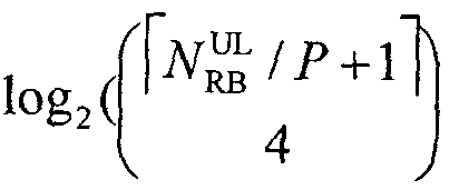
- a method for transmitting an uplink signal in a wireless communication system comprising: receiving a control channel signal including a resource allocation field; And There is provided a method comprising transmitting an uplink signal according to a control channel signal, wherein the size of the resource field is given by the following equation:
- N represents the number of UL (UpLik) RB (Resource Block),
- P represents UL RBG (Resource Block Group) size
- ⁇ ( ⁇ ,;) represents the increase of X and y
- a communication device of a wireless communications system a radio frequency (Radio Frequency, RF) unit; And a processor, wherein the processor is configured to receive a control channel signal including a resource allocation field and to transmit an uplink signal according to the control channel signal, wherein the resource allocation information is used to indicate two resource sets.
- each resource block set includes one or more contiguous resource block groups (RBGs), wherein the size of the resource allocation field is given by the following equation. :
- rc (x, _y) represents the larger of x and y and ifclh ⁇ Z ll
- P is given by the following table:
- the UL RBG size represents the number of consecutive RBs.
- the resource allocation field includes information indicating a combination index r used to indicate two resource block sets, each resource block set includes one or more consecutive RBGs, and the combination index r is Given by the equation:
- N is the number of UL RBGs +1
- s 2 and s 3 are used to indicate the starting RBG index and the ending RBG index of the second resource block set.
- the start and end RBG indexes of the first resource block set are so and Sl ⁇ 1, and the start and end RBG indexes of the second resource block set are s 2 and s 3 ⁇ l, respectively.
- 1 satisfies ⁇ ⁇ s' ⁇ N and.
- log 2 bits indicating the combination index r is
- control channel signal is a PDCOK Physical Downlink Control Channel (PDCOK) signal
- uplink signal is a PUSCH (Physical Uplink Shared Channel) signal.
- PDCOK Physical Downlink Control Channel
- PUSCH Physical Uplink Shared Channel
- resources can be efficiently allocated in a wireless communication system. Specifically, it is possible to efficiently perform continuous or discontinuous resource allocation for uplink transmission.
- FIG. 1 illustrates a structure of a radio frame of a 3GPP system.
- FIG. 2 illustrates a resource grid of a downlink slot.
- 3 shows a structure of a downlink subframe.
- . 5 shows a virtual resource block (VRB) and physical
- PRB Physical Resource Block
- 6A and 6C illustrate resource allocation types 0 to 2 of legacy LTE.
- DFT-s-OFDMA Discrete Fourier Transform Spread Orthogonal Frequency Division Multiple Access
- 11 through 13 illustrate a method of discontinuous uplink resource allocation according to an embodiment of the present invention.
- 16 illustrates an uplink transmission process according to an embodiment of the present invention.
- 17 illustrates a base station and a terminal that can be applied to an embodiment of the present invention.
- CDMA code division multiple access
- FDMA frequency division multiple access
- FDMA TDMACtime division multiple access
- OFDMA orthogonal frequency division multiple access
- SC-FDMA single carrier frequency division multiple access
- CDMA may be implemented with radio technologies such as Universal Terrestrial Radio Access (UTRA) or CDMA2000.
- TDMA may be implemented in a wireless technology such as Global System for Mobile Communications (GSM) / General Packet Radio Service (GPRS) / Enhanced Data Rates for GSM Evolution (EDGE).
- GSM Global System for Mobile Communications
- GPRS General Packet Radio Service
- EDGE Enhanced Data Rates for GSM Evolution
- 0FDMA may be implemented by a radio technology such as IEEE 802.11 (Wi-Fi), IEEE 802.16 (WiMAX), IEEE 802-20, E to ETRA (Uvolved UTRA).
- UTRA is part of the UMTS Jniversal Mobile Telecom unicat ions System.
- 3GPP LTEdong term evolution (3GPP) is part of Evolved UMTS (E-UMTS) using E-UTRA and employs 0FMA in downlink and SOFDMA in uplink.
- LTE ⁇ A Advanced is an evolution of 3GPP LTE.
- 1 illustrates the structure of a radio frame.
- the wireless frame includes 10 sub-frames.
- Subframe includes two slots in the "time domain.
- the time for transmitting a subframe is defined as a transmission time interval (TTI).
- TTI transmission time interval
- one subframe may have a length of 1 ms, and one slot may have a length of 0.5 ms.
- One slot includes multiple 0rthogonal frequency divisions in the time domain. Multiplexing) or SC to FDMA (Single Carrier Frequency Division Multiple Access) symbol. Since 3GPP LTE uses OFDMA in downlink and SC-FDMA in uplink, OFDM or SC-FDMA symbols represent one symbol period.
- a resource block (RB) is a resource allocation unit and includes a plurality of consecutive subcarriers in one slot.
- the structure of a radio frame is shown for illustrative purposes. Accordingly, the number of subframes included in the wireless frame, the number of slots included in the subframe, and the number of symbols included in the slot may be modified in various ways.
- 2 illustrates a resource grid of a downlink slot.
- the downlink pilot includes a plurality of OFDM symbols in the time domain.
- One downlink slot may include 7 (6) OFDM symbols and the resource block may include 12 subcarriers in the frequency domain.
- Each element on the resource grid is referred to as a resource element (RE).
- One RB contains 12X7 (6) REs.
- the number N of RBs included in the downlink slot depends on the downlink transmission band.
- the structure of an uplink slot is the same as that of a downlink slot, except that an OFDM symbol is replaced with an SOFDMA symbol and N is replaced with N.
- 3 illustrates a structure of a downlink subframe.
- up to three (4) OFDM symbols located at the front of the first slot of a subframe are indicated in a control region to which a control channel is allocated.
- the remaining OFDM symbols correspond to data regions to which PDSCH (Physical Downlink Shared CHancel) is allocated.
- Examples of a downlink control channel used in 3GPP LTE include a Physical Control Format Indicator Channel (PCFICH), a Physical Downlink Control Channel (PDCCH), a Physical Hybrid ARQ Indicator Channel (PHICH), and the like.
- the PCFICH is transmitted in the first OFDM symbol of a subframe and carries information on the number of OFDM symbols used for transmission of a control channel within the subframe.
- the PHICH carries an HARQ ACK / NACK (acknowledgment / negat i-acknowledgment) signal as an answer of uplink transmission.
- DCI Downlink Control Information
- Tx uplink transmission
- the PDCCH includes transmission format and resource allocation information of a downlink shared channel (DL-SCH), transmission format and resource allocation information of an uplink shared channel (UL (SCH), and a paging channel. , Resource allocation information of higher-layer control messages such as paging information on PCH), system information on DL-SCH, random access response transmitted on PDSCH, Tx power control command set for individual terminals in a terminal group, and Tx power control. Command, and activation instruction information of Voice over IP (VoIP).
- Multiple PDCCHs may be transmitted in the control region.
- the terminal may monitor the plurality of PDCCHs.
- the PDCCH is transmitted on an aggregation of one or a plurality of consecutive control channel elements (CCEs).
- CCEs control channel elements
- CCE is a logical allocation unit used to provide a coding rate based on the radio channel state to the PDCCH.
- CCEs are applied to a plurality of resource element groups (REGs).
- the format of the PDCCH and the number of PDCCH bits are determined according to the number of CCEs.
- the base station determines the PDCCH format according to the DCI to be transmitted to the terminal, and adds a CRC cyclic redundancy check to the control information.
- the CRC is masked (or scrambled) with an identifier (eg, RNTKradio network temporary ident i fier) depending on the owner or purpose of use of the PDCCH.
- an identifier eg, RNTKradio network temporary ident i fier
- an identifier eg, cell-RNTI (C-RNTI)
- C-RNTI cell-RNTI
- P-RNTI paging-RNTI
- SI-RNTI system information RNTI
- RA-RNTI random access-RNTI
- FIG. 4 illustrates a structure of an uplink subframe used in LTE.
- the uplink subframe includes a plurality (eg, two) slots.
- the slot may include different numbers of SC-FDMA symbols according to CP (CycIic Prefix) lengths. For example, in case of a normal CP, a slot may include 7 SC-FDMA symbols.
- the uplink subframe is divided into a data region and a control region in the frequency domain.
- the data area includes a PUSCH and is used to transmit data signals such as voice.
- the control region includes a PUCCH and is used to transmit control information.
- the control information includes HARQACK / NACK, Channel Quality Information (CQI), PMKPrecoding Matrix Indicator (RQ), Rank Indication (RI), and the like.
- Physical Resource Blocks PRBs
- Virtual Resource Blocks VRBs
- the physical resource block is the same as that illustrated in FIG. That is, the physical resource block is w s D y ; b contiguous OFDM symbols and contiguous subcarriers in the frequency domain. Physical resource blocks are numbered 0 through JV L -1 in the frequency domain. The relationship between the physical resource block number ( « PRB ) and the resource element in the slot is shown in Equation 1.
- V s represents the number of subcarriers included in one resource block.
- the virtual resource block has the same size as the physical resource block.
- Localized virtual resource blocks (Localized VRB, LVRB) and distributed type virtual resource blocks (Distributed VRB, DVRB) are defined. Regardless of the type of virtual resource block, a pair of resource blocks are allocated together by a single virtual resource block number ( « VRB ) over two slots in a subframe.
- FIG. 5 illustrates a method of mapping a virtual resource block to a physical resource block.
- N gap represents the frequency interval (eg, PRB unit) when VRBs of the same number are mapped to PRBs of the first slot and the second slot.
- a gap is defined value (gap - gaP '1).
- two gap values ( ⁇ aP ' 1 and gaP' 2 ) are defined.
- g ap - ⁇ gaP '1 or ⁇ ;
- ⁇ is signaled via downlink scheduling.
- N VRB numbers constitute a unit for VRB number interleaving
- VRB number interleaving of each interleaving unit may be performed using four columns and four rows.
- o w ⁇ ⁇ ⁇ ⁇ ⁇ and denotes the size of the resource block group (RBG).
- RBG is defined as P consecutive resource blocks.
- VRB numbers are in a matrix
- frequency resource allocation may be indicated through a PDCCH in every subframe.
- PRB Physical RB
- the PRB of the first half of the subframe ie, the first slot
- PRB Physical RB
- the PRB of the same frequency of the second half ie, the second slot
- this specification is described in terms of the first half of the subframe.
- Existing LTE uses "number of ways as shown in Table 2-3 for the resource allocation.
- Table 2 shows a downlink (DL) resource allocation method
- Table 3 shows an uplink (UL) resource allocation method.
- ⁇ 3 ⁇ 4 represents an uplink bandwidth expressed in multiples of N. That is, N ⁇ represents uplink bandwidth and the unit is RB.
- P represents the number of RBs constituting the RBG.
- 6A, 6B and 6C show Type 0 Resource Allocation (RA), Type 1 RA and Type, respectively.
- FIG. 2 shows an example of a control information format for RA and resource allocation accordingly.
- the terminal interprets the resource allocation field based on the detected PDCCH DCI format.
- the resource allocation field in each PDCCH is composed of the resource allocation header field and the actual resource block allocation information. It contains two parts.
- PDCCH DCI formats 1, 2, and 2A for type 0 and type 1 resource allocation are distinguished from each other through a single bit resource allocation header field having the same format and existing according to a downlink system band. Specifically, type 0 RA is indicated as 0 and type 1 RA is indicated as 1.
- PDCCH DCI formats 1A, IB, 1C and ID are used for Type 2 RAs, while PDCCH DCI formats 1, 2 and 2A are used for Type 0 or Type 1 RAs.
- PDCCH DCI format with Type 2 RA does not have a resource allocation header field.
- the resource block allocation information in the type 0 RA includes a bitmap indicating a resource block group (RBG) allocated to the terminal.
- RBG is a set of contiguous PRBs.
- RBG size (P) depends on the system band as shown in Table 4.
- the size of the bitmap is ⁇ ⁇ (3 and each bit represents one RBG.
- the entire RBG is indexed from 0 to iV RBG -l in the direction of frequency increase, and RBG 0 to RBGNRBG-1 is the MSB of the bitmap. Mapped from most significant bit) to least significant bit (LSB).
- the resource block allocation information having a size of ⁇ In Type 1 RA indicates to the scheduled UE the resource in the RBG subset in PRB units.
- RBG subset P (0 ⁇ ⁇ ⁇ ) consists of every Pth RBG starting from RBG p.
- Resource block allocation information consists of three fields. The first field is ( " k> g 2 (/ l bits and indicates the RBG subset selected from the P RBG subsets. The second field is 1 bit and shifts the resource allocation span within the subset. If the bit value is 1. Is triggered and vice versa.
- the third field contains a bitmap, each bit indicating one PRB in the selected RBG set. These RBG 'bitmap section that is used to indicate the PRB in the subset is the size of ⁇ ⁇ ⁇ ⁇ , are defined as Equation (2).
- the addressable PRB number in the selected RBG subset may start from the offset (A sh , ft Cp) for the smallest PRB number in the selected RBG subset and map to the MSB of the bitmap.
- N RB Cp represents the number of PRBs in the RBG subset p
- the resource block allocation information in a type 2 RA indicates a set of LVRBs or DVRBs continuously allocated to the scheduled UE.
- a 1-bit flag indicates whether an LVRB or DVRB is allocated (eg, 0 indicates LVRB allocation and 1 indicates DVRB allocation).
- Type 2 resource allocation field may include a resource indication value (Resource Indication Value, RIV), and RIV Corresponds to the starting resource block (/?..) And the length. The length represents the number of resource blocks allocated virtually consecutively.
- the DFT-s-OFDMA scheme differs from the 0FDMA scheme in that a plurality of data symbols (ie, data symbol sequences) are spread in the frequency domain through DFT precoding before IFFT processing.
- the DFT-s-OFDMA scheme is referred to as the SC-FDMA scheme and both are commonly used herein.
- the DFT-s-OFD transmitter 700 includes constellation mapping modules 702, serial / parallel converter 704, Nu-point FFT spreading modules 706, and symbol-to-subcarrier mapping module 708. Nc 'point IFFT module 710, pre-circulation modulus 712 and bottle / serial converter 714.
- the DFT-s-OFDMA transmitter 700 may further include additional models.
- some models may be implemented as a module by integrating functions with each other.
- Nu corresponds to the number of scheduled subcarriers as the FFT spreading mode input size.
- Nc corresponds to the total number of subcarriers present in the system band. Accordingly, the Nu value and thus the DFT input / output size may vary within a range of Nu ⁇ Nc depending on the amount of data symbols scheduled at every scheduling time.
- Signal processing of the DFT-s-OFDMA transmitter 700 is as follows. First, a bit stream is modulated into a data symbol sequence (702). The serial data symbol sequences are then converted in parallel by Nu (704). Nu-length parallel data symbol sequences are converted into Nu-length frequency domain sequences through the same sized FFT process (706). FFT processing may be performed via Nu-point DFT processing. In this specification, FFT is commonly used with DFT, and DFT processing is commonly used with DFT diffusion or DFT precoding. Thereafter, the Nu-length frequency domain sequence is mapped to the allocated Nu subcarriers among the total Nc subcarriers, and 0 is padded to the remaining Nc-Nu subcarriers (708).
- the sequence mapped to the Nc subcarrier is converted into an Nc length time domain sequence through Nc-point IFFT processing (710).
- the cyclic prefix is obtained by copying the last Np samples of the time domain sequence and adding them to the front of the sequence.
- Configure a Cyclic Prefix (712) The generated cataract region sequence corresponds to one transmission symbol and is converted into a serial sequence through a parallel / serial converter (714). After that, the serial sequence is transmitted to the receiver through a process such as frequency upconversion.
- the other user receives the available subcarriers from the remaining Nc-Nu subcarriers used by the previous user and transmits the data.
- the receiver 720 includes a serial / parallel converter 722, an Nc-point FFT models 724, a subcarrier-to-symbol mapping mode 726, and a Nu-point two FT despreading modules 728. , Bottle / serial transformer 730 and constellation demapping modules 732.
- the signal processing of the receiver 720 consists of the inverse of the transmitter 700, so see FIG. 7A for details.
- 0FDMA is used for downlink and SC-FDMA is used for uplink.
- the 0FDMA transmitter corresponds to removing the Nu-point FFT spreading modules 706 from the block diagram of FIG.
- Nu-point DFT despreading modules 728 corresponds to the removal of Nu-point DFT despreading modules 728 from the block diagram of FIG. 7B.
- 8 illustrates a block diagram of a localized DFT-s-OFDMA transmitter. 8 corresponds to a resource allocation method of the existing LTE.
- the frequency domain sequence output from the DFT module 806 is mapped to consecutive subcarriers within the system band. That is, a frequency domain sequence of length Nu is mapped to Nu consecutive subcarriers.
- a frequency domain sequence of length Nu is mapped to Nu consecutive subcarriers.
- 9 illustrates a blotting degree of a clustered DFT-s-OFDMA transmitter.
- 9 corresponds to a resource allocation method additionally used in LTE-A.
- the LTE-A terminal may use the scheme of FIG. 8 or the scheme of FIG. 9 based on the resource allocation information.
- the frequency domain sequence output from the DFT models 906 is discontinuously mapped discontinuously in the frequency band (908).
- This method can be said to independently apply the localized DFT—s—0FDMA method to a plurality of distant frequency domains.
- each resource set (or frequency band) to which the localized DFT-s-OFDMA scheme is applied is referred to as a cluster.
- the cluster includes one or more contiguous subcarriers. Therefore, in the present scheme, a plurality of data symbols that have undergone DFT precoding are mapped to consecutive subcarriers in M ( ⁇ 1) clusters separated from each other in the frequency domain. 9 illustrates the case of three clusters.
- each cluster eg 1, the number of subcarriers, RBs, or RBGs
- the size of each cluster may be set independently. If the M value is greater than 1, the PAPR value of the transmitted signal is larger than the localized DFT-s-OFDMA method, but if the M value is set within an appropriately small range, it still guarantees a smaller PAPR value than the 0FDMA method and improves scheduling flexibility. can do.
- UL RA Type 1 As a discontinuous uplink resource allocation method (referred to as UL RA Type 1 for convenience) is introduced into the LTE-A system, various methods for efficiently signaling UL RA Type 1 have been discussed in the art.
- a method using a bit system that individually indicates a UL RB (or RBG) has been proposed, such as DL RA type 0.
- complete scheduling freedom is ensured in discontinuous resource allocation, but if there are n RBs (or RBGs) in the UL band, an amount of control information may be excessively increased since n bits of RA fields are required.
- the size of the RA field for the existing PUSCH scheduling is set to 10 ⁇ 2 3 ⁇ 43 ⁇ 4 + 1) 2)]
- a new DCI format must be defined to support the present scheme.
- a method of recycling an existing continuous allocation method (RA type 2) but limiting a resource area to which each cluster can be allocated has been proposed.
- the first cluster may be allocated only in RBG 0-4 and the second cluster may be allocated only in RBG 5-9.
- the size of the RA field may be given as 2. "10 ⁇ ( ⁇ . (+ 1) / 2)”.
- N erSpa "represents the size of the area to which each cluster can be allocated and is in RBG units. According to the present scheme, it is preferable to perform discontinuous resource allocation using the existing RA field by adjusting the size of N ⁇ T Span . However, there is a problem in that scheduling freedom is reduced because the area to which each cluster can be allocated is limited.
- the present invention proposes to use a combination index corresponding to a plurality of discontinuously allocated resource sets.
- the combination index may be included in the RA field of the DCI format for PUSCH scheduling.
- the combination index is used to indicate when a particular combination of indices is selected in the whole case.
- a set of indexes of a particular combination is denoted by ⁇ ⁇ 0 _1 .
- M ' 2 M, where M represents the number of allocated resource sets (eg, clusters). In this case, corresponds to the first set of resources, and a to the second set of resources.
- the total UL system bandwidth black defines N as the total number of RBs corresponding to the UL bandwidth available for resource allocation.
- ⁇ may be set to the same value (ie, cell-specific) in all terminals, or may be set independently for each terminal (ie, UE-specific).
- 10 shows an example of an RBG indexing based RBG map for resource allocation. 10 is
- the RBG is composed of two RBs. Therefore, RB # 1 to # 20 are RBG #. Grouped from 1 to # 10.
- RBG is used as a basic UL resource allocation unit. The figure illustrates that the RB index and the RBG index start at 1, but depending on the implementation, the RB index and / or The RBG index may be defined to start at zero.
- Method 1 The combination index points to the combination of RBG indexes,
- the method illustrates a method of allocating a plurality of discontinuous uplink resource sets (eg, RBG clusters) based on RBG indexing.
- RBG clusters discontinuous uplink resource sets
- S and E the starting RBG index and the ending RBG index of the RBG cluster allocated to the terminal
- E m The starting RBG index and ending RBG index of the m th RBG set
- E m the combination index
- Method 1—1 Initiating a Starting / Ending-Rear RBG of an RBG Cluster
- FIG. 11 illustrates a resource allocation scheme according to Method 1-1.
- the method is based on RBG indexing and includes ⁇ S surge, E m + l ⁇ (ie, starting RBG indexes) for each of the M RBG clusters allocated to UEs among all N RBG RBGs. End -Information of the next RBG index
- the combined index included in the DCI format for PUSCH scheduling indicates the seed '( ⁇ '-SA /), and the UE has a fe ⁇ + l ⁇ . You can check ⁇ S fatigue, E from the relationship.
- one virtual RBG may be further defined behind the last RBG index (high RBG index direction) as shown in FIG. 11.
- the last RBG index high RBG index direction
- N N RBG
- the total number of RBG indexes is N + 1 including virtual RBGs. Therefore, the number of bits required for resource allocation in the present method becomes ceiling (log 2 ( N + 1 C 2M )).
- a combination index ⁇ " for signaling M RBG cluster resource allocations may be expressed as follows. [Equation 4]
- a combination index r for signaling M RBG cluster resource allocations may be expressed as follows.
- N may be given by the following equation.
- N represents the number of resource blocks in the uplink band.
- RBG It indicates the number of resource blocks to configure.
- 1 represents a ceiling function.
- Table 5 illustrates the RBG size (P) according to the system band.
- ( ⁇ + ⁇ ⁇ may be interpreted as the starting RBG index of the unallocated RBG region adjacent to the rear of the m th RBG cluster.
- Method 1-2 Initiating RBG Cluster—Indicating a Starting / Front / Ending RBG
- FIG. 12 illustrates a resource allocation scheme according to Method 1-1.
- the method is based on RBG indexing.
- ⁇ S m -E that is, the RBG index before the start and the end RBG indexes.
- the combination index included in the DCI format for PUSCH scheduling indicates ⁇ ⁇ / '- ⁇ ) and indicates that the UE
- all indexes of all clusters can be jointly encoded together.
- a combination index r for signaling M RBG cluster resource allocations may be expressed as in Equation 4.
- the combination index r for signaling the M RBG cluster resource allocation can be expressed as in Equation 5.
- the method illustrates a method of allocating a plurality of discontinuous uplink resource sets (eg, RBG clusters) based on RBG border indexing.
- RBG boundary index and the end RBG boundary index of the RBG cluster allocated to the terminal are referred to as SB and EB, respectively.
- the starting RBG boundary index and the ending RBG boundary index of the m th RBG set are referred to as S3 ⁇ 4 and E, respectively.
- 13A-B illustrate a resource allocation scheme according to Method 2.
- the method is based on the RBG boundary indexing, and for each of the M RBG clusters allocated to the UE among the N RBG RBGs, ⁇ SB m , EB (ie, the starting RBG boundary index and the ending RBG).
- the combination index included in the DCI format for PUSCH scheduling indicates ( ⁇ ! M ⁇ S), and the UE indicates ⁇ SB m , from the relation of ⁇ canvas ⁇ ⁇ ⁇ , ⁇ . You can check the EB.
- ⁇ T ' ⁇ s ⁇ V + l ⁇ , ⁇ nee means the RBG boundary index of the shot dog. Indicates.
- a combination index r for signaling ⁇ RBG cluster resource allocation can be expressed as follows.
- the terminal receives resource allocation information including a combination index from a network node (eg, a base station or a relay) (S1402).
- the field for resource allocation information is included in the DCI and may be received through a downlink control channel (eg, PDCCH).
- PDCCH downlink control channel
- the UE performs a process for PUSCH transmission based on the PDCCH information in subframe n + 4.
- the terminal interprets the resource allocation information.
- the terminal acquires a mesh 0 for the combination index (S1404), and checks the resource set corresponding to the combination index.
- RBG clusters a resource set allocated from a network node (eg, a base station or a relay)
- PUSCH uplink shared channel
- RBG 15 shows an example of interpretation of resource allocation information according to an embodiment of the present invention.
- the number of RBGs is 9 and two resource sets (eg, RBG clusters) are allocated.
- Each resource set consists of contiguous resources (eg RBG).
- Method 1-2 and Method 2 are used to transmit an uplink signal.
- RBG # 3 and RBG # 6-8 are used to transmit the uplink signal.
- RBG # 3 and RBG # 6-8 are used to transmit the uplink signal.
- the foregoing description focuses on discontinuous uplink resource allocation.
- UL RA type 0 continuous uplink resource allocation
- ULRA type 1 discontinuous uplink resource allocation
- Two resource allocation schemes may be signaled through the same DCI format.
- a resource allocation type that is actually applied may be distinguished using flag bits. For example, as in DL RA type 0 ⁇ , one bit flag (referred to as RA type bit for convenience) is placed in DCI format for PUSCH scheduling, and it is possible to selectively signal ULRA type 0 and ULRA type 1 through this. Do.
- RBG size P (that is, (maximum) P RBs per RBG) for DL RA is defined as described in Table 5 according to the BW size (eg, the number of DL RBs in DL BW).
- DCI format 0 for UL scheduling in LTE supports RA Type 2 based on Resource Indication Value (RIV), and the number of bits constituting the RA field is
- LTE-A also considers UL BL continuous RA that allocates two BG clusters by applying the existing DCI format 0 without changing the RA field size based on the RBG size defined in the existing LTE. To do this, include up to 1-bit FH flags (i.e. no FH during non-continuous RA) It may be considered to use +1 bit as an RA field.
- FH flags i.e. no FH during non-continuous RA
- Table 6 shows the RBG size ⁇ and the number of RBGs N for each BW in LTE calculated based on Table 5.
- Gray shaded portions (BW: 7, 9-10, 55-63, 85-90, 101 in Table 6) -110 RBs) is O c! r ⁇ 0 represents BW that does not satisfy DCI0 .
- Alt 0 Supports discontinuous RA only for BW satisfying O clmer ⁇ O DC10 %, Alt 1) changing a part of the RBG size by BW, which is defined in the existing LTE, Alt 2), but accept the RBG by size BW defined in the existing LTE, additionally defines a BW that RA is applied,
- Alt 3 RBG black, to which RA is applicable by RRC signaling, indicates an RB range
- Alt 4 Extends the RA field by borrowing / adding specific bits in DCI format 0;
- O ctor ⁇ O for BW satisfying OCT0 support both the existing LTE system-based continuous RIV RA and RA discontinuously in the proposed method, 1,2-based, and O dus, er> O for a BW that Da0 continuously RA If the RA type bit indicates a discontinuous RA method in the BW where O duster> O DC10 , the UE may consider that an error has occurred and drop the UL transmission.
- the size of the B UL RBG may be changed as shown in Table 7 0 ⁇ ⁇ ⁇ ] ⁇ / 1,
- RBG size can be changed as shown in Table 8. ).
- one RBG excluded from the RA target may be an RBG having a first or last RBG index.
- the RBG having the last RBG index may be excluded.
- two RBGs excluded from the RA subject may be RBGs having a first RBG index and a last RBG index. Since the PUCCH transmission hops to the opposite side of the frequency band on the slot boundary, the RBG excluded from both ends of the frequency band can be utilized for PUCCH signal transmission.
- the RBG indexability based on Table 5 may be applied, and BW to which RA is applied (simply, RA target BW and BWRA) may be separately defined.
- BW to which RA is applied (simply, RA target BW and BWRA) may be separately defined.
- the BWRA is excluded from the actual BW.
- RA can only be applied to RBG) ( ⁇ ).
- one excluded RBG may be an RBG having a last RBG index. This is because the number of RBs constituting the last RBG may be less than or less.
- two excluded RBGs may be RBGs having a first RBG index and a last RBG index. This is to increase the efficiency of the PUCCH resources, considering that the PUCCH transmission hops to the opposite side of the frequency band to the boundary of the slot.
- the three excluded RBGs may be RBGs having a first RBG index, a last RBG index, and an index adjacent to the last RBG index (ie, the last RBG index minus one). Table 10 illustrates according to BW.
- UL RB number A L ' EX excluded from actual BW can be defined as shown in Table 11.
- the excluded RB may be RBs corresponding to the first ⁇ -1 RB indexes and the last a RB indexes.
- the excluded RBs may be RBs corresponding to the first ⁇ RB indexes and the last ⁇ RB indexes.
- RRC signaling indicates the applicable RBG or RB range.
- UL RBG range to which RA is applied through RRC signaling implies, UL RBG range for RA, RBGKA range.
- RBGRAs after applying RBG indexing based on Table 5 only to the corresponding RBGs (ie, RBGRAs), RA may be applied only to the corresponding RBG range.
- RBGRA range the starting RBG index and / or the last RBG index of the range, or the starting RBG index and the number of consecutive RBGs may be informed.
- an RB range (simplified RA target RB range, RBRA range) to which A is applied may be indicated through R C signaling.
- the RA after applying the indexing based on Table 5 only to the corresponding RBs (ie, the RBRAs), the RA may be applied only to the corresponding RB range.
- the starting RB index and / or the last RB index of the range, or the starting RB index and the number of consecutive RBs may be informed.
- DCI format 0 Specific bits in DCI format 0 may be borrowed and included in the RA field in discontinuous RA.
- one bit of the CQI request field in DCI format 0 may be used / interpreted as part of the RA field. Since the CQI request field is composed of 1 bit, the function of the CQI request is disabled in discontinuous RA. That is, the base station cannot indicate the CQI request when applying discontinuous RA.
- one bit of a 3-bit field indicating a Cyclic Shift (CS) of a DeModulation Reference Signal (DMRS) may be borrowed and included in the RA field.
- CS Cyclic Shift
- DMRS DeModulation Reference Signal
- two bits among the three bits constituting the DMRS CS field are used to indicate the CS of the DMRS according to the original use, and one bit is used / interpreted as a part of the RA field.
- Table 12 illustrates the BB-specific RBG size for the present scheme.
- Table 12 exemplifies a case in which one bit is borrowed from another field to expand the size of the RA field.
- LTE-A considers a method of performing dynamic / aperiodic SRS transmission for multi-antenna transmission and butt traffic processing in addition to periodic SRS transmission in the existing LTE.
- a scheme of triggering dynamic / aperiodic SRS transmission through the PDCCH may be considered, and a scheme of adding 1 bit for SRS trigger to the DCI format may also be considered.
- a method of borrowing one bit for SRS trigger in the RA field may be considered.
- the SRS trigger function is automatically disabled when applying the discontinuous RA, and the base station and the terminal use / interpret the corresponding 1 bit as part of the RA field (that is, when the discontinuous RA is applied, the base station may indicate the SRS trigger. Can not).
- DCI format 0 eg. 1 bit of CQI request field
- 1 bit of the DMRS CS field and 1 bit of the SRS trigger field may be set as an RA field or used as an original function through RRC signaling.
- a method of adding one bit to DCI format 0 for the purpose of extending the RA field without borrowing the specific bit may be considered.
- adding one bit to the RA field of the DCI format 0 is limited to the UE-specific search space for the PDCCH. Can be applied.
- the scheme of Alt 4 is only for BW where O ctoer > O oao , ie the gray shaded parts of Table 6 (BW: 7, 9-10, 55-63, 85-90, 101-110 RBs) Can be applied.
- Equation 9 The total number of bits O DCI0 (excluding the 1-bit FH flag) can be newly defined as shown in Equation 9 below.
- O DC / 0 represents the number of bits of the RA field for RBG allocation.
- N represents the number of UL RBGs.
- N represents the number of UL RBs.
- P represents UL RBG size.
- the UL RBG size may be given as shown in Table 5 according to the BW. " " ] Represents the ceiling function, ⁇ ( ⁇ ,;) represents the larger of ⁇ and y. ⁇ Represents the number of cases where y is selected from x .
- X c y
- a method of newly defining an RA field of DCI format 0 may be applied only to the UE-specific search space. Accordingly, in the case of the RA field for LTE-A DCI format 0 in the common search space, after allocating the same as the RA field size of the existing LTE DCI format 0, the proposed Alt 0 to 4 or all Consideration may be given to not supporting discontinuous RAs for the event.
- the BW is 10 RB or less
- discontinuous RA may not be applied. Accordingly, all the proposed Alt 0 to 5 may not be applied to the BW of 10 RB or less.
- the RA field of the DCI format 0 to which Alt 0 to 5 is applied (1-bit FH)
- the number of bits constituting the flag is assumed to be the number of bits required for the N 1 discontinuous RA.
- discontinuous RA the following may be considered by arranging 3 ⁇ 4 bits in the bit RA field when ⁇ ⁇ 1.
- the RA field configuration bit order starts from the 1-bit FH flag. Is defined as ( ⁇ means FH flag).
- the remaining Ni-Mi bit (s) which do not correspond to the ⁇ bits allocated through 1), 2), and 3) are set to a predetermined value (eg, ' all zeros ' ) for error detection. It can be used for virtual CRC purposes.
- the number of bits constituting the RA field (except 1 ⁇ bit FH flag) of DCI format 0 to which Alt 0 to 5 is applied, and the number of bits required for consecutive RA (except 1 bit bit FH flag) are M 2 .
- M 2 ⁇ N 2 the following may be considered as a method of disposing M 2 bits in an N 2 bit RA field.
- the RA field configuration bit order excluding the 1-bit FH flag is defined as-, b N ⁇ .
- the remaining N 2 -M 2 bit (s) which do not correspond to the M 2 bits allocated through 1) and 2) are set to a predetermined value (eg, all set to 0) to detect an error. Can be used for virtual CRC purposes.
- LTE-A can support uplink multi-antenna (port) transmission, and a new DCI format for UL MIM0 scheduling (ie, DCI format X) can be newly defined.
- DCI format X a new DCI format for UL MIM0 scheduling
- discontinuous RA may be supported even when UL MIM0 is transmitted, and the RA field in DCI format X may be designed in consideration of this. Frequency hopping is not supported in ULMIM0, which may result in undefined 1-bit FH flags. Accordingly, when discontinuous RA is applied using DCI format X, the RA field size of DCI format X is allocated to be equal to the RA field size of the existing DCI format 0 (including 1-bit FH flag) (3 ⁇ 4 OT). +1) and Alt 0 to 4 may be applied (Alt 0-4).
- the total number of bits in the RA field is ⁇ 3 ⁇ 4 OT below.
- Alt 5 Can be newly defined as an expression (Alt 5).
- O dc! X represents the number of bits of the RA field for RBG allocation.
- N represents the number of UL RBGs.
- the UL RBG size may be given as shown in Table 5 according to the UL BW.”] Represents a ceiling function.
- M (x, _y ) Represents the greater of x and y, where ⁇ is x
- blind decoding may be performed independently of other DCI formats. Therefore, in the proposed Alt 4, the method of adding 1 bit to the RA field and the Alt 5 based Equation 10, common search space and UE-specific search It can be applied in common without any distinction of space.
- K may be considered as a method of arranging K bits in the RA field. If the size of the RA field is different from the size of the RA information, it may occur in the following cases.
- Alt-5 the case of Alt-5 will be explained mainly. According to Alt # 5, the size of the RA field in the set UL BW is determined to be a larger value between the RA information size of RA type 0 and the information size of RA type 1.
- the size of the RA information may be small.
- the size of the RA information may be smaller than the size of the RA field.
- the RA field configuration bit order is defined as ⁇ ,, ⁇ .. ,.
- the remaining L-K bit (s), which do not correspond to the K bits allocated through 1) and 2), are set to a predetermined value (eg, all set to 0) and used for virtual CRC for error detection. Can be used.
- FIG 16 illustrates an uplink transmission process according to an embodiment of the present invention. For convenience, it is assumed that Alt 5 is applied.
- the base station broadcasts system information to the terminal (S1602).
- the system information includes information about the system band (BW).
- the information on the uplink BW includes information.
- the uplink BW may be given using the number of UL RBs.
- the base station transmits a PDCCH signal for uplink scheduling to the terminal (S1604).
- the PDCCH signal includes a DCI format for uplink scheduling.
- the PDCCH signal In the single antenna (port) transmission mode, the PDCCH signal includes DCI format 0.
- the PDCCH signal is in DCI format X. Include. DCI format 0 / X includes a resource allocation (RA) type bit and a resource allocation (RA) field.
- the RA type bit is used to indicate RA type 0 or 1 and may consist of 1 bit.
- RA field is ULRBG . Used for assignment.
- the size of the RA field can be given by Equations 9-12 (eg Max
- the terminal interprets the RA type bit and the RA field of the PDCCH signal and allocates a resource for PUSCH transmission (S1604).
- a resource for PUSCH transmission is composed of one or more consecutive RB (s) according to the RIV value of the RA field.
- the resource for PUSCH transmission is composed of two continuous clusters according to the combination index of the RA field (see FIGS. 11 to 15). Each cluster consists of one or more contiguous RBG (s).
- the terminal transmits the PUSCH signal to the base station by using the allocated resource (S1606).
- FIG. 17 illustrates a base station and a terminal that can be applied to an embodiment of the present invention.
- the illustrated block diagram of a base station-terminal may be replaced by a block diagram of a base station-relay and a block diagram of a relay-terminal.
- a wireless communication system includes a base station (BS) 110 and a terminal (UE) 120.
- Base station 110 includes a processor 112, a memory 114, and a radio frequency (RF) unit 116.
- the processor 11.2 may be configured to implement the procedures and / or methods proposed in the present invention.
- the memory 114 is connected with the processor 112 and stores various information related to the operation of the processor 112.
- the RF unit 116 is connected with the processor 112 and transmits and / or receives a radio signal.
- Terminal 120 includes a processor 122, a memory 124, and an RF unit 126.
- the processor 122 may be configured to implement the procedures and / or methods proposed in the present invention.
- the memory 124 is connected with the processor 122 and stores various information related to the operation of the processor 122.
- the RF unit 126 is connected with the processor 122 and transmits and / or receives a radio signal.
- the base station 110 and / or the terminal 120 may have a single antenna or multiple antennas.
- the embodiments described above are in the form of elements and features of the present invention. Combined. Each component or feature is to be considered optional unless stated otherwise. Each component or feature may be embodied in a form that is not combined with other components or features. It is also possible to combine some of the components and / or features to form an embodiment of the invention. The order of the operations described in the embodiments of the present invention may be changed.
- embodiments of the present invention have been mainly described based on data transmission / reception relations between a terminal and a base station.
- Certain operations described in this document as being performed by a base station may, in some cases, be performed by their upper node. That is, it is apparent that various operations performed for communication with a terminal in a network including a plurality of network nodes including a base station may be performed by the base station or network nodes other than the base station.
- a base station may be replaced by terms such as a fixed station, a Node B, an eNode B (eNB), an access point, etc.
- the terminal may be a user equipment (UE) or a mobi le stat ion (MS). Or MSS (Mobile Subscriber Station).
- an embodiment of the present invention may be implemented in the form of a module, procedure, function, etc. that performs the functions or operations described above.
- the software code may be stored in a memory unit and driven by a processor.
- the memory unit may be located inside or outside the processor, and may exchange data with the processor by various known means.
- the present invention can be used in a wireless communication device such as a terminal, a relay, a base station, and the like.
Landscapes
- Engineering & Computer Science (AREA)
- Signal Processing (AREA)
- Computer Networks & Wireless Communication (AREA)
- Physics & Mathematics (AREA)
- Discrete Mathematics (AREA)
- General Physics & Mathematics (AREA)
- Mathematical Physics (AREA)
- Mobile Radio Communication Systems (AREA)
- Digital Transmission Methods That Use Modulated Carrier Waves (AREA)
- Radio Transmission System (AREA)
Abstract
Description


Claims





Priority Applications (15)
| Application Number | Priority Date | Filing Date | Title |
|---|---|---|---|
| ES11825416.8T ES2654346T3 (es) | 2010-09-14 | 2011-09-14 | Método y dispositivo para asignación de recursos de enlace ascendente |
| CN201180041569.7A CN103081385B (zh) | 2010-09-14 | 2011-09-14 | 用于上行链路资源分配的方法和装置 |
| RU2013108808/07A RU2529880C1 (ru) | 2010-09-14 | 2011-09-14 | Способ и устройство для распределения ресурсов восходящей линии связи |
| KR1020167022892A KR101683125B1 (ko) | 2010-09-14 | 2011-09-14 | 상향링크 자원 할당을 위한 방법 및 장치 |
| MX2013000981A MX2013000981A (es) | 2010-09-14 | 2011-09-14 | Metodo y dispositivo para asignacion de recursos de enlace ascendente. |
| JP2013520679A JP5629377B2 (ja) | 2010-09-14 | 2011-09-14 | アップリンクリソース割当のための方法及び装置 |
| KR1020167033274A KR102019131B1 (ko) | 2010-09-14 | 2011-09-14 | 상향링크 자원 할당을 위한 방법 및 장치 |
| US13/805,312 US8737344B2 (en) | 2010-09-14 | 2011-09-14 | Method and device for uplink resource allocation |
| EP17187470.4A EP3264846B1 (en) | 2010-09-14 | 2011-09-14 | Method and device for uplink resource allocation |
| KR1020127024326A KR101654064B1 (ko) | 2010-09-14 | 2011-09-14 | 상향링크 자원 할당을 위한 방법 및 장치 |
| EP11825416.8A EP2618505B1 (en) | 2010-09-14 | 2011-09-14 | Method and device for uplink resource allocation |
| US13/770,742 US8867474B2 (en) | 2010-09-14 | 2013-02-19 | Method and device for uplink resource allocation |
| US14/221,120 US9197384B2 (en) | 2010-09-14 | 2014-03-20 | Method and device for uplink resource allocation |
| US14/853,722 US9706535B2 (en) | 2010-09-14 | 2015-09-14 | Method and device for uplink resource allocation |
| US15/603,937 US10368341B2 (en) | 2010-09-14 | 2017-05-24 | Method and device for uplink resource allocation |
Applications Claiming Priority (8)
| Application Number | Priority Date | Filing Date | Title |
|---|---|---|---|
| US38289010P | 2010-09-14 | 2010-09-14 | |
| US61/382,890 | 2010-09-14 | ||
| US41439810P | 2010-11-16 | 2010-11-16 | |
| US61/414,398 | 2010-11-16 | ||
| US41923410P | 2010-12-02 | 2010-12-02 | |
| US61/419,234 | 2010-12-02 | ||
| US42265510P | 2010-12-13 | 2010-12-13 | |
| US61/422,655 | 2010-12-13 |
Related Child Applications (3)
| Application Number | Title | Priority Date | Filing Date |
|---|---|---|---|
| US13/805,312 A-371-Of-International US8737344B2 (en) | 2010-09-14 | 2011-09-14 | Method and device for uplink resource allocation |
| US13/770,742 Continuation US8867474B2 (en) | 2010-09-14 | 2013-02-19 | Method and device for uplink resource allocation |
| US14/221,120 Continuation US9197384B2 (en) | 2010-09-14 | 2014-03-20 | Method and device for uplink resource allocation |
Publications (2)
| Publication Number | Publication Date |
|---|---|
| WO2012036456A2 true WO2012036456A2 (ko) | 2012-03-22 |
| WO2012036456A3 WO2012036456A3 (ko) | 2012-05-31 |
Family
ID=45832092
Family Applications (1)
| Application Number | Title | Priority Date | Filing Date |
|---|---|---|---|
| PCT/KR2011/006770 Ceased WO2012036456A2 (ko) | 2010-09-14 | 2011-09-14 | 상향링크 자원 할당을 위한 방법 및 장치 |
Country Status (9)
| Country | Link |
|---|---|
| US (5) | US8737344B2 (ko) |
| EP (2) | EP2618505B1 (ko) |
| JP (3) | JP5629377B2 (ko) |
| KR (3) | KR101683125B1 (ko) |
| CN (2) | CN103081385B (ko) |
| ES (1) | ES2654346T3 (ko) |
| MX (1) | MX2013000981A (ko) |
| RU (1) | RU2529880C1 (ko) |
| WO (1) | WO2012036456A2 (ko) |
Cited By (1)
| Publication number | Priority date | Publication date | Assignee | Title |
|---|---|---|---|---|
| CN112567848A (zh) * | 2018-08-20 | 2021-03-26 | 韦勒斯标准与技术协会公司 | 无线通信系统中接收物理控制信道的方法及使用其的设备 |
Families Citing this family (58)
| Publication number | Priority date | Publication date | Assignee | Title |
|---|---|---|---|---|
| KR950002639B1 (ko) | 1988-11-23 | 1995-03-23 | 카덴스 에바이론멘탈 에너지, 인코포레이티드 | 환경보존적인 고체 폐기물 처리와 이것을 행하기 위한 개선된 습식 또는 건식처리 회전식 건조로 |
| EP2352242B1 (en) * | 2008-10-29 | 2018-03-07 | Sharp Kabushiki Kaisha | Wireless communication system, mobile station device, and base station device |
| KR20110126034A (ko) * | 2010-05-14 | 2011-11-22 | 엘지전자 주식회사 | 무선 통신 시스템에서 비주기적 사운딩 참조 신호 전송 방법 및 장치 |
| KR101615985B1 (ko) | 2010-05-24 | 2016-05-12 | 엘지전자 주식회사 | 불연속적 상향링크 자원 할당을 위한 방법 및 장치 |
| EP2584828B1 (en) | 2010-06-21 | 2019-03-13 | Sun Patent Trust | Notification of resource allocation information from a base station apparatus to a terminal apparatus |
| US9094175B2 (en) | 2010-07-16 | 2015-07-28 | Qualcomm, Incorporated | Method and apparatus for saving power by using signal field of preamble |
| CN103081385B (zh) | 2010-09-14 | 2016-02-17 | Lg电子株式会社 | 用于上行链路资源分配的方法和装置 |
| CN102781110B (zh) * | 2011-05-12 | 2015-04-01 | 中兴通讯股份有限公司 | 具有跳频功能的资源位置分配方法及装置 |
| US20130142094A1 (en) * | 2011-12-02 | 2013-06-06 | Qualcomm Incorporated | Systems and methods for frame filtering and for enabling frame filtering |
| US20130242901A1 (en) * | 2012-03-13 | 2013-09-19 | Innovative Sonic Corporation | Method and apparatus for delivering an operating parameter of a new carrier in a wireless communication network |
| CN103327615B (zh) * | 2012-03-20 | 2016-04-20 | 华为技术有限公司 | 资源分配指示方法、资源分配方法及设备 |
| KR101895997B1 (ko) * | 2013-06-24 | 2018-09-06 | 한국전자통신연구원 | 주파수 분할 다중 접속을 위한 송신기 및 수신기 |
| US11743897B2 (en) | 2013-12-20 | 2023-08-29 | Qualcomm Incorporated | Techniques for configuring uplink channels in unlicensed radio frequency spectrum bands |
| CN105981316B (zh) | 2014-02-13 | 2018-07-06 | Lg电子株式会社 | 在支持机器型通信的无线接入系统中发送探测参考信号的方法和设备 |
| WO2016019553A1 (zh) * | 2014-08-07 | 2016-02-11 | 华为技术有限公司 | 物理下行数据信道传输方法、基站及用户设备 |
| KR20220145420A (ko) * | 2014-08-15 | 2022-10-28 | 인터디지탈 패튼 홀딩스, 인크 | 감소된 대역폭을 갖는 wtru에 대한 업링크 송신 및 mbms를 지원하기 위한 방법 및 장치 |
| US9603140B2 (en) * | 2014-09-23 | 2017-03-21 | Intel Corporation | Resource allocation |
| WO2016099140A1 (ko) | 2014-12-16 | 2016-06-23 | 엘지전자(주) | 무선 통신 시스템에서 데이터 전송 방법 및 이를 위한 장치 |
| US10367551B2 (en) * | 2015-01-29 | 2019-07-30 | Intel Corporation | Precoding resource block group bundling enhancement for full dimension multi-in-multi-output |
| EP3314798B1 (en) * | 2015-06-29 | 2019-08-14 | Telefonaktiebolaget LM Ericsson (publ) | Combination of different signal streams in a point-to-point transmition using a plurality of different frequency components |
| EP4012945B1 (en) * | 2015-07-03 | 2025-04-09 | Telefonaktiebolaget LM Ericsson (publ) | A network node, a wireless device and respective method performed thereby for communicating therebetween |
| US9756641B2 (en) * | 2015-07-07 | 2017-09-05 | Qualcomm Incorporated | Dynamic signaling of LTE-TDD configurations in the presence of D2D transmissions |
| US10383105B2 (en) * | 2015-07-12 | 2019-08-13 | Lg Electronics Inc. | Method and device for transmitting control information in wireless communication system |
| JP6633084B2 (ja) * | 2015-08-21 | 2020-01-22 | 株式会社Nttドコモ | ユーザ端末、無線基地局及び無線通信方法 |
| CN106559202B (zh) * | 2015-09-29 | 2019-09-10 | 上海朗帛通信技术有限公司 | 一种支持低空口延迟的方法、用户设备和基站设备 |
| CN106561066B (zh) * | 2015-10-02 | 2019-07-05 | 上海朗帛通信技术有限公司 | 无线通信中的一种降低网络延迟的方法和装置 |
| CN106656444B (zh) * | 2015-11-03 | 2019-03-26 | 中兴通讯股份有限公司 | 一种资源分配方法及装置 |
| WO2017160107A2 (ko) * | 2016-03-16 | 2017-09-21 | 엘지전자 주식회사 | 무선 통신 시스템에서 무선 신호 송수신 방법 및 장치 |
| EP3866541B1 (en) | 2016-03-18 | 2023-12-27 | Huawei Technologies Co., Ltd. | Network node, user device and methods thereof |
| US10122559B2 (en) | 2016-03-21 | 2018-11-06 | Qualcomm Incorporated | Uplink channel quality measurement using a subframe with high-intensity reference signal bursts |
| KR20170112897A (ko) * | 2016-03-31 | 2017-10-12 | 삼성전자주식회사 | 이동 통신 시스템에서의 채널 상태 정보 보고 모드 설정 방법 및 장치 |
| KR20170134238A (ko) * | 2016-05-27 | 2017-12-06 | 주식회사 아이티엘 | Nr 시스템을 위한 제어 채널 및 데이터 채널 송수신 방법 및 장치 |
| WO2017204595A1 (ko) | 2016-05-27 | 2017-11-30 | 주식회사 아이티엘 | Nr 시스템을 위한 제어 채널 및 데이터 채널 송수신 방법 및 장치 |
| JP2020017776A (ja) * | 2016-11-02 | 2020-01-30 | 株式会社Nttドコモ | 基地局及びユーザ装置 |
| CN108347776B (zh) * | 2017-01-25 | 2023-11-10 | 华为技术有限公司 | 一种通信系统中资源分配的方法及设备 |
| CN111491379B (zh) | 2017-05-05 | 2021-05-18 | 华为技术有限公司 | 资源分配的方法、用户设备和网络设备 |
| KR101950995B1 (ko) * | 2017-06-08 | 2019-02-22 | 엘지전자 주식회사 | 무선 통신 시스템에서 자원 할당 관련 시그널링 방법 및 상기 방법을 이용하는 장치 |
| EP3624520B1 (en) * | 2017-06-08 | 2021-09-01 | Guangdong Oppo Mobile Telecommunications Corp., Ltd. | Data transmission method, terminal device and network device |
| EP3639587A4 (en) * | 2017-06-16 | 2020-06-03 | ZTE Corporation | SYSTEM AND METHOD FOR ASSIGNING RESOURCE BLOCKS |
| CN110771063B (zh) | 2017-06-22 | 2023-09-01 | Lg电子株式会社 | 在无线通信系统中报告信道状态的方法和装置 |
| CN112564880B (zh) * | 2017-08-11 | 2022-11-01 | Oppo广东移动通信有限公司 | 数据处理方法及相关设备 |
| CN109548149B (zh) | 2017-09-21 | 2020-11-10 | 电信科学技术研究院 | 一种rbg的划分方法和用户终端 |
| US20190158332A1 (en) * | 2017-11-17 | 2019-05-23 | Qualcomm Incorporated | Resource block indexing |
| CN111373812B (zh) * | 2017-11-17 | 2023-04-18 | 中兴通讯股份有限公司 | 用于分配资源块的系统和方法 |
| US10841143B2 (en) * | 2017-12-12 | 2020-11-17 | Qualcomm Incorporated | Phase tracking reference signal for sub-symbol phase tracking |
| KR101954433B1 (ko) | 2018-01-11 | 2019-03-05 | 엘지전자 주식회사 | 무선 통신 시스템에서 단말의 하향링크 신호 수신 방법 및 상기 방법을 이용하는 단말 |
| ES3036068T3 (en) | 2018-01-13 | 2025-09-12 | Wilus Inst Standards & Tech Inc | Resource allocation method, device and system of wireless communication system |
| US11012112B2 (en) * | 2018-02-09 | 2021-05-18 | Qualcomm Incorporated | Techniques for flexible resource allocation |
| EP3833062B1 (en) | 2018-08-10 | 2023-01-25 | Huawei Technologies Co., Ltd. | Resource allocation method and device in tdd system |
| US11166267B2 (en) * | 2018-08-17 | 2021-11-02 | Qualcomm Incorporated | DCI triggered SRS enhancements |
| US11290999B2 (en) * | 2018-09-06 | 2022-03-29 | Qualcomm Incorporated | Techniques for flexible resource allocation |
| JP7156887B2 (ja) * | 2018-09-27 | 2022-10-19 | シャープ株式会社 | 端末装置、基地局装置、および、通信方法 |
| CN112566251B (zh) * | 2019-09-26 | 2025-01-17 | 苹果公司 | 用于多trp传输的下行链路控制 |
| CN112702789B (zh) * | 2020-12-03 | 2022-11-18 | 杭州红岭通信息科技有限公司 | 一种物理上行共享信道的资源分配方法 |
| US11424851B2 (en) * | 2020-12-09 | 2022-08-23 | Qualcomm Incorporated | Dynamic bit width determination for resource block group mask |
| CN116762387A (zh) * | 2021-01-15 | 2023-09-15 | 高通股份有限公司 | 每个搜索空间集组的pdcch监听能力指示 |
| US11716711B2 (en) * | 2021-03-11 | 2023-08-01 | Qualcomm Incorporated | Time domain resource allocation for a time domain waveform |
| KR102905068B1 (ko) | 2021-12-07 | 2025-12-29 | 엘지전자 주식회사 | 의류처리장치 |
Family Cites Families (27)
| Publication number | Priority date | Publication date | Assignee | Title |
|---|---|---|---|---|
| KR20050081528A (ko) * | 2004-02-14 | 2005-08-19 | 삼성전자주식회사 | 다중반송파 통신시스템을 위한 채널 상태정보 피드백 방법 |
| US7584397B2 (en) * | 2004-06-10 | 2009-09-01 | Interdigital Technology Corporation | Method and apparatus for dynamically adjusting data transmission parameters and controlling H-ARQ processes |
| RU2414105C2 (ru) * | 2005-06-14 | 2011-03-10 | Нтт Досомо, Инк. | Мобильная станция, базовая станция и способ осуществления связи |
| JP4295300B2 (ja) | 2006-08-22 | 2009-07-15 | 株式会社エヌ・ティ・ティ・ドコモ | 送信装置及び送信方法 |
| KR20090118072A (ko) | 2007-03-01 | 2009-11-17 | 가부시키가이샤 엔티티 도코모 | 기지국장치 및 통신제어방법 |
| US9137821B2 (en) | 2007-05-02 | 2015-09-15 | Qualcomm Incorporated | Flexible signaling of resources on a control channel |
| JP4574659B2 (ja) | 2007-10-01 | 2010-11-04 | 株式会社エヌ・ティ・ティ・ドコモ | 移動局装置、上りリンク送信方法、および通信システム |
| CN101472300A (zh) * | 2007-12-29 | 2009-07-01 | 华为技术有限公司 | 发送和接收调度用户数据的信息的方法、装置和系统 |
| EP2106057A1 (en) * | 2008-03-25 | 2009-09-30 | Panasonic Corporation | Resource allocation size dependent transport block size signalling |
| WO2009119067A1 (ja) * | 2008-03-25 | 2009-10-01 | パナソニック株式会社 | 無線通信基地局装置および無線通信方法 |
| KR101478240B1 (ko) * | 2008-05-06 | 2015-01-06 | 삼성전자주식회사 | 무선 통신 시스템의 자원 할당 방법 및 이를 위한 무선통신 시스템 |
| KR100921467B1 (ko) * | 2008-06-19 | 2009-10-13 | 엘지전자 주식회사 | 셀룰라 다중반송파 시스템에서 조밀도를 조절하는 자원할당시그널링 방식 |
| KR101565417B1 (ko) * | 2008-08-08 | 2015-11-03 | 엘지전자 주식회사 | 다중 주파수 대역 시스템에서의 자원 할당하는 방법 및 장치 |
| ES2982360T3 (es) | 2008-08-08 | 2024-10-15 | Sun Patent Trust | Dispositivo de estación base de comunicación inalámbrica, dispositivo terminal de comunicación inalámbrica y método de asignación de canales |
| EP2166804A1 (en) * | 2008-09-17 | 2010-03-24 | Panasonic Corporation | Deactivation of semi-persistent resource allocations in a mobile communication network |
| US20110205995A1 (en) * | 2008-10-28 | 2011-08-25 | Nokia Corporation | Physical downlink control channel configuration for extended bandwidth systems |
| KR101557676B1 (ko) | 2008-10-31 | 2015-10-06 | 삼성전자주식회사 | 이동무선 통신시스템의 하향링크 제어채널의 페이로드 크기결정장치 및 방법 |
| GB2464987A (en) * | 2008-11-03 | 2010-05-05 | Nec Corp | Methods for designating resource allocation |
| KR100956828B1 (ko) * | 2008-11-13 | 2010-05-11 | 엘지전자 주식회사 | 반(半)-지속적 스케줄링의 비활성화를 지시하는 방법 및 이를 이용한 장치 |
| US20100195748A1 (en) * | 2009-02-02 | 2010-08-05 | Samsung Electronics Co., Ltd. | Method and system for reference signal pattern design in resource blocks |
| KR20110014101A (ko) * | 2009-08-04 | 2011-02-10 | 엘지전자 주식회사 | 릴레이 백홀 자원 할당 |
| CN101657018B (zh) * | 2009-08-18 | 2015-01-28 | 中兴通讯股份有限公司 | 无线信道资源分配的指示方法及基站、解码方法及终端 |
| US20110069637A1 (en) * | 2009-09-18 | 2011-03-24 | Futurewei Technologies, Inc. | System and Method for Control Channel Search Space Location Indication for a Relay Backhaul Link |
| US9055576B2 (en) * | 2009-10-08 | 2015-06-09 | Qualcomm Incorporated | Uplink resource allocation for LTE advanced |
| US9949261B2 (en) * | 2009-10-15 | 2018-04-17 | Qualcomm Incorporated | Method and apparatus for conveying resource assignment for multiple system bandwidths |
| CN101801093A (zh) * | 2010-02-03 | 2010-08-11 | 中兴通讯股份有限公司 | 资源分配方式指示方法、装置和系统 |
| CN103081385B (zh) | 2010-09-14 | 2016-02-17 | Lg电子株式会社 | 用于上行链路资源分配的方法和装置 |
-
2011
- 2011-09-14 CN CN201180041569.7A patent/CN103081385B/zh not_active Expired - Fee Related
- 2011-09-14 ES ES11825416.8T patent/ES2654346T3/es active Active
- 2011-09-14 KR KR1020167022892A patent/KR101683125B1/ko active Active
- 2011-09-14 EP EP11825416.8A patent/EP2618505B1/en not_active Not-in-force
- 2011-09-14 EP EP17187470.4A patent/EP3264846B1/en active Active
- 2011-09-14 KR KR1020127024326A patent/KR101654064B1/ko active Active
- 2011-09-14 KR KR1020167033274A patent/KR102019131B1/ko active Active
- 2011-09-14 WO PCT/KR2011/006770 patent/WO2012036456A2/ko not_active Ceased
- 2011-09-14 RU RU2013108808/07A patent/RU2529880C1/ru active
- 2011-09-14 CN CN201610036957.0A patent/CN105681011B/zh active Active
- 2011-09-14 US US13/805,312 patent/US8737344B2/en active Active
- 2011-09-14 JP JP2013520679A patent/JP5629377B2/ja not_active Expired - Fee Related
- 2011-09-14 MX MX2013000981A patent/MX2013000981A/es active IP Right Grant
-
2013
- 2013-02-19 US US13/770,742 patent/US8867474B2/en active Active
-
2014
- 2014-03-20 US US14/221,120 patent/US9197384B2/en active Active
- 2014-10-02 JP JP2014204058A patent/JP5911545B2/ja not_active Expired - Fee Related
-
2015
- 2015-09-14 US US14/853,722 patent/US9706535B2/en active Active
-
2016
- 2016-03-28 JP JP2016063283A patent/JP6073514B2/ja active Active
-
2017
- 2017-05-24 US US15/603,937 patent/US10368341B2/en active Active
Non-Patent Citations (2)
| Title |
|---|
| None |
| See also references of EP2618505A4 |
Cited By (2)
| Publication number | Priority date | Publication date | Assignee | Title |
|---|---|---|---|---|
| CN112567848A (zh) * | 2018-08-20 | 2021-03-26 | 韦勒斯标准与技术协会公司 | 无线通信系统中接收物理控制信道的方法及使用其的设备 |
| US12426061B2 (en) | 2018-08-20 | 2025-09-23 | Wilus Institute Of Standards And Technology Inc. | Method for receiving physical control channel in wireless communication system, and device using same |
Also Published As
Similar Documents
| Publication | Publication Date | Title |
|---|---|---|
| WO2012036456A2 (ko) | 상향링크 자원 할당을 위한 방법 및 장치 | |
| KR101615985B1 (ko) | 불연속적 상향링크 자원 할당을 위한 방법 및 장치 | |
| CN113424474B (zh) | 在无线通信系统中发送上行链路控制信道的装置和方法 | |
| KR102241122B1 (ko) | 무선 통신시스템의 제어 채널의 전송 및 수신방법, 장치 및 시스템 | |
| CN115765922B (zh) | 发送或接收数据信道和控制信道的方法、装置和系统 | |
| JP7761970B2 (ja) | 無線通信システムにおいて物理下りリンク制御チャネルを送信する方法及びそのための装置 | |
| JP2013529414A (ja) | 制御チャネル要素への制御情報の対応付け |
Legal Events
| Date | Code | Title | Description |
|---|---|---|---|
| WWE | Wipo information: entry into national phase |
Ref document number: 201180041569.7 Country of ref document: CN |
|
| 121 | Ep: the epo has been informed by wipo that ep was designated in this application |
Ref document number: 11825416 Country of ref document: EP Kind code of ref document: A2 |
|
| ENP | Entry into the national phase |
Ref document number: 20127024326 Country of ref document: KR Kind code of ref document: A |
|
| WWE | Wipo information: entry into national phase |
Ref document number: 13805312 Country of ref document: US |
|
| ENP | Entry into the national phase |
Ref document number: 2013520679 Country of ref document: JP Kind code of ref document: A |
|
| REEP | Request for entry into the european phase |
Ref document number: 2011825416 Country of ref document: EP |
|
| WWE | Wipo information: entry into national phase |
Ref document number: 2011825416 Country of ref document: EP |
|
| WWE | Wipo information: entry into national phase |
Ref document number: MX/A/2013/000981 Country of ref document: MX |
|
| NENP | Non-entry into the national phase |
Ref country code: DE |
|
| ENP | Entry into the national phase |
Ref document number: 2013108808 Country of ref document: RU Kind code of ref document: A |