WO2012042731A1 - 配管の支持構造 - Google Patents
配管の支持構造 Download PDFInfo
- Publication number
- WO2012042731A1 WO2012042731A1 PCT/JP2011/004612 JP2011004612W WO2012042731A1 WO 2012042731 A1 WO2012042731 A1 WO 2012042731A1 JP 2011004612 W JP2011004612 W JP 2011004612W WO 2012042731 A1 WO2012042731 A1 WO 2012042731A1
- Authority
- WO
- WIPO (PCT)
- Prior art keywords
- force
- fluid
- coriolis
- hose
- clamp
- Prior art date
- Legal status (The legal status is an assumption and is not a legal conclusion. Google has not performed a legal analysis and makes no representation as to the accuracy of the status listed.)
- Ceased
Links
Images


Classifications
-
- F—MECHANICAL ENGINEERING; LIGHTING; HEATING; WEAPONS; BLASTING
- F16—ENGINEERING ELEMENTS AND UNITS; GENERAL MEASURES FOR PRODUCING AND MAINTAINING EFFECTIVE FUNCTIONING OF MACHINES OR INSTALLATIONS; THERMAL INSULATION IN GENERAL
- F16L—PIPES; JOINTS OR FITTINGS FOR PIPES; SUPPORTS FOR PIPES, CABLES OR PROTECTIVE TUBING; MEANS FOR THERMAL INSULATION IN GENERAL
- F16L3/00—Supports for pipes, cables or protective tubing, e.g. hangers, holders, clamps, cleats, clips, brackets
- F16L3/16—Supports for pipes, cables or protective tubing, e.g. hangers, holders, clamps, cleats, clips, brackets with special provision allowing movement of the pipe
-
- F—MECHANICAL ENGINEERING; LIGHTING; HEATING; WEAPONS; BLASTING
- F16—ENGINEERING ELEMENTS AND UNITS; GENERAL MEASURES FOR PRODUCING AND MAINTAINING EFFECTIVE FUNCTIONING OF MACHINES OR INSTALLATIONS; THERMAL INSULATION IN GENERAL
- F16L—PIPES; JOINTS OR FITTINGS FOR PIPES; SUPPORTS FOR PIPES, CABLES OR PROTECTIVE TUBING; MEANS FOR THERMAL INSULATION IN GENERAL
- F16L11/00—Hoses, i.e. flexible pipes
- F16L11/04—Hoses, i.e. flexible pipes made of rubber or flexible plastics
- F16L11/08—Hoses, i.e. flexible pipes made of rubber or flexible plastics with reinforcements embedded in the wall
-
- F—MECHANICAL ENGINEERING; LIGHTING; HEATING; WEAPONS; BLASTING
- F16—ENGINEERING ELEMENTS AND UNITS; GENERAL MEASURES FOR PRODUCING AND MAINTAINING EFFECTIVE FUNCTIONING OF MACHINES OR INSTALLATIONS; THERMAL INSULATION IN GENERAL
- F16L—PIPES; JOINTS OR FITTINGS FOR PIPES; SUPPORTS FOR PIPES, CABLES OR PROTECTIVE TUBING; MEANS FOR THERMAL INSULATION IN GENERAL
- F16L55/00—Devices or appurtenances for use in, or in connection with, pipes or pipe systems
- F16L55/02—Energy absorbers; Noise absorbers
- F16L55/033—Noise absorbers
- F16L55/035—Noise absorbers in the form of specially adapted hangers or supports
-
- F—MECHANICAL ENGINEERING; LIGHTING; HEATING; WEAPONS; BLASTING
- F16—ENGINEERING ELEMENTS AND UNITS; GENERAL MEASURES FOR PRODUCING AND MAINTAINING EFFECTIVE FUNCTIONING OF MACHINES OR INSTALLATIONS; THERMAL INSULATION IN GENERAL
- F16D—COUPLINGS FOR TRANSMITTING ROTATION; CLUTCHES; BRAKES
- F16D48/00—External control of clutches
- F16D48/02—Control by fluid pressure
- F16D2048/0224—Details of conduits, connectors or the adaptors therefor specially adapted for clutch control
-
- Y—GENERAL TAGGING OF NEW TECHNOLOGICAL DEVELOPMENTS; GENERAL TAGGING OF CROSS-SECTIONAL TECHNOLOGIES SPANNING OVER SEVERAL SECTIONS OF THE IPC; TECHNICAL SUBJECTS COVERED BY FORMER USPC CROSS-REFERENCE ART COLLECTIONS [XRACs] AND DIGESTS
- Y10—TECHNICAL SUBJECTS COVERED BY FORMER USPC
- Y10T—TECHNICAL SUBJECTS COVERED BY FORMER US CLASSIFICATION
- Y10T29/00—Metal working
- Y10T29/49—Method of mechanical manufacture
- Y10T29/49826—Assembling or joining
- Y10T29/49947—Assembling or joining by applying separate fastener
- Y10T29/49959—Nonresilient fastener
Definitions
- the present invention relates to a pipe support structure, and more particularly to a pipe support structure through which a high-temperature fluid flows.
- hydraulic oil is supplied to a hydraulic device such as an actuator that is driven and controlled by hydraulic pressure through a pipe.
- a hydraulic device such as an actuator that is driven and controlled by hydraulic pressure
- Such an actuator that is driven and controlled by hydraulic pressure is mounted on a vehicle such as an automobile, and is used to control various driving devices of the vehicle.
- a brake system including a master cylinder and a pipe that connects a hydraulic unit is known (see, for example, Patent Document 1).
- the pipe connecting the master cylinder and the hydraulic unit is a metal pipe, and a metal wire is meshed on the outer periphery of a resin hose formed at an intermediate portion of the metal pipe. And a flexible hose coated. For this reason, by using a flexible hose that is less rigid than the metal pipe, it is possible to finely adjust the piping shape corresponding to the mounting error of the relative position between the master cylinder and the hydraulic unit. Absorption of vibration that can be transmitted to the master cylinder side is enabled.
- piping used in the hydraulic system such as the brake system described above may include only resin piping in consideration of the degree of freedom of mounting in a vehicle.
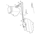
- An example of a hydraulic system using such resin piping is shown in FIG.
- a resin pipe 103 bent at a predetermined radius of curvature is used between the hydraulic power unit 101 and the gear shift actuator 102.
- the resin pipe 103 is clamped by a support member 105 at an arbitrary position.
- the hydraulic oil output from the hydraulic power unit 101 is supplied to the gear shift actuator 102 via the resin pipe 103.
- Such a resin pipe 103 shown in FIG. 13 is bent at a predetermined radius of curvature and is inclined at a predetermined angle with respect to a horizontal plane as it goes from the hydraulic power unit 101 toward the bent portion 103a.
- oil When oil is supplied, it vibrates in the vertical direction according to the flow of the hydraulic oil.
- a so-called Coriolis force F (F 2 m ⁇ V, m: fluid mass, ⁇ : fluid angular velocity, V: flow velocity in the pipe in a direction orthogonal to the flow direction of the hydraulic oil. ) Occurs.
- the resin pipe 103 receives a reaction force F ′ from the support member 105 so as to oppose the Coriolis force F (N).
- the Coriolis force F described above increases as the flow rate (ml / s) of hydraulic fluid flowing through the resin pipe 103 increases or the temperature (° C.) of the hydraulic fluid increases. It has been known.
- the Coriolis force F and the reaction force F ′ acting on the resin pipe 103 change with time as shown in FIG.
- the Coriolis force F and the reaction force F ′ are components facing each other, but their magnitudes do not match. That is, as time passes, a state occurs in which the magnitude of the Coriolis force F exceeds the magnitude of the reaction force F ′, or conversely, the magnitude of the reaction force F ′ exceeds the magnitude of the Coriolis force F.
- the resin pipe 103 is crushed, and the flow speed of the hydraulic fluid flowing in the resin pipe 103 is increased.
- the oil pressure becomes larger than the set value.
- the balance between the Coriolis force F and the reaction force F ′ is not taken into consideration, which is one of the factors hindering the stable supply of hydraulic pressure.
- the hydraulic oil flowing in the resin pipe 103 is used.
- Changes in the rigidity of the piping due to temperature changes affect the position control and responsiveness of hydraulic equipment such as the gear shift actuator 102.
- the rigidity of the resin pipe 103 decreases, and the expansion amount of the resin pipe 103, that is, the so-called hose compliance amount increases.
- the hydraulic pressure in the resin pipe 103 is reduced, and in particular, the responsiveness of hydraulic equipment such as the gear shift actuator 102 is deteriorated.
- a hydraulic system such as a sensor, coolant, heat insulating material, and an electronic control unit (ECU: Electronic Control Unit) that performs temperature environment control, etc.
- ECU Electronic Control Unit
- the resin pipe 103 shown in FIG. 13 has a problem that no countermeasure is taken for the balance between the generated Coriolis force F and the reaction force F ′.
- An object of the present invention is to provide a piping support structure capable of suppressing the amount of hose compliance in a high temperature range with a simple and low-cost configuration.
- the pipe support structure according to the present invention is supported at the first clamp position and the second clamp position, and has a fluid passage through which a high-temperature fluid flows, and is formed of an elastic material.
- a holding member that elastically holds an outer periphery of the pipe at at least one of the first clamp position and the second clamp position, and the pipe has a gravity direction.
- a bent portion having a predetermined radius of curvature between the first clamp position and the second clamp position, and the holding member has a predetermined spring constant.
- the spring constant and the damping coefficient of the holding member are set so that the amount is controlled. It has the composition to do.
- the reaction force generated in the holding member according to the Coriolis force generated in the pipe acts to suppress the thermal expansion amount of the pipe.
- at least one of the first clamp position and the second clamp position and the shape of the bent portion are set, and the spring constant and the damping coefficient of the holding member are set.
- the piping support structure according to the present invention can utilize the generated Coriolis force and the reaction force generated in the holding member.
- the piping support structure according to the present invention can suppress the hose compliance amount in the high temperature range, that is, the expansion amount of the piping, while maintaining the mounting flexibility specific to the piping made of an elastic member such as resin. Realized with a simple and low-cost configuration.
- the pipe support structure according to the present invention is preferably the pipe support structure, wherein the Coriolis force is F c , the fluid angular velocity of the fluid flowing through the fluid passage is ⁇ , and the time is t.
- the piping support structure according to the present invention sets the first clamp position, the second clamp position, the shape of the bent portion, the spring constant, and the damping coefficient so that the coefficient ⁇ in Equation (1) approaches 1. Since this is done, the Coriolis forcing force f c (t) and the clamping reaction force f r (t) act so as to cancel each other. For this reason, the clamping reaction force f r (t) can be converted into a pressing load on the pipe, and the amount of expansion of the pipe can be suppressed.
- the fluid mass of the fluid flowing in the fluid passage between the first clamp position and the second clamp position is m
- the Coriolis force F c is expressed by the following equation (2):
- the fluid density of the fluid is ⁇
- the flow rate of the fluid flowing in the fluid passage between the first clamp position and the second clamp position is v
- the curvature radius of the bent portion is r (2)
- the fluid mass m and the fluid angular velocity ⁇ are expressed by the following equations (3) and (4), respectively.
- the Coriolis forcing force f c (t) adjust the Coriolis force F c is the amplitude has a configuration which is adapted to adjust the fluid angular velocity ⁇ by adjusting the radius of curvature r of the bent portion.
- the piping support structure according to the present invention adjusts the fluid mass m represented by the equation (3) by adjusting the position of at least one of the first clamp position and the second clamp position.
- the Coriolis force F c that is the amplitude of the Coriolis forcing force f c (t) is adjusted.
- the fluid angular velocity ⁇ represented by the equation (4) is adjusted by adjusting the curvature radius r of the bent portion.
- the pipe support structure according to the present invention can adjust the Coriolis forcing force f c (t) only by adjusting the first clamp position, the second clamp position, and the curvature radius r of the bent portion.
- the reaction force F r indicating the amplitude of the force f r (t) and the phase difference ⁇ are expressed by the following equations (5) and (6), respectively.
- the damping coefficient is h
- the total mass of the fluid mass of the whole fluid passage and the mass of the pipe is M
- the natural angular frequency ⁇ n and the damping ratio ⁇ in the equations (5) and (6) above. are represented by the following equations (7) and (8), respectively:
- the phase difference ⁇ and the reaction force F r are adjusted by adjusting the spring constant k and the damping coefficient h.
- the phase difference ⁇ and the reaction force F r are adjusted by adjusting the spring constant k and the damping coefficient h.
- the pipe support structure according to the present invention can be obtained simply by appropriately selecting a holding member having the optimum spring constant k and damping coefficient h from among holding members having different spring constants k and damping coefficients h.
- the clamping reaction force f r (t) can be adjusted according to the forcing force f c (t).
- the present invention by using the generated Coriolis force and reaction force, it is possible to easily and inexpensively suppress the hose compliance amount in a high temperature range while maintaining the mounting flexibility specific to resin piping. It is possible to provide a piping support structure that can be realized by the above.
- FIG. 1 is a schematic configuration diagram schematically illustrating a configuration of a vehicle to which a piping support structure according to an embodiment of the present invention is applied. It is a perspective view which shows the connection state of the master hose and return hose which concern on embodiment of this invention. It is a perspective view which shows the support structure of piping which concerns on embodiment of this invention. It is a front view of the master side clamp part which concerns on embodiment of this invention. It is a sectional side view of the master side clamp part which concerns on embodiment of this invention. It is a side view which shows the support structure of piping which concerns on embodiment of this invention. It is the side view which showed typically the master hose which concerns on embodiment of this invention.
- a vehicle 1 to which a piping support structure according to an embodiment of the present invention is applied will be described with reference to FIG. First, the configuration will be described.
- the vehicle 1 includes an engine (not shown) as a drive source, a clutch mechanism (not shown), and an AMT (Automated Manual Transmission) 4.
- the clutch mechanism and the AMT 4 are connected via a torque tube (not shown).
- the engine is composed of a known power device that outputs power by burning a mixture of hydrocarbon fuel such as gasoline or light oil and air in a combustion chamber of a cylinder (not shown).
- This engine is a crankshaft (not shown) that is connected to the piston so as to transmit power by reciprocating the piston in the cylinder by repeatedly performing a series of intake, compression, combustion, and exhaust strokes of the air-fuel mixture in the combustion chamber. Is supposed to rotate.
- the clutch mechanism is provided between the engine and the AMT4.
- the clutch mechanism includes a clutch actuator (not shown), a flywheel connected to the crankshaft of the engine, and a clutch disk that rotates in synchronization with the input shaft of the AMT 4 that is rotatably supported in the torque tube. .
- This clutch mechanism is configured to switch between a transmission state in which the rotation of the engine is transmitted to the AMT 4 and a cut-off state in which the transmission is interrupted by engaging or releasing the flywheel and the clutch disk by a clutch actuator.
- the clutch actuator is connected to a later-described HPU 11 via a pipe (not shown), and engages or releases the flywheel and the clutch disk in accordance with the hydraulic pressure supplied from the HPU 11.
- the AMT 4 includes a transaxle case 4a, a gear unit (not shown) that forms, for example, 1st to 6th gears in the forward traveling state of the vehicle 1, a gear shift actuator (hereinafter referred to simply as GSA) 10, And a hydraulic power unit (Hydraulic Power Unit: hereinafter simply referred to as HPU) 11.
- the gear unit is accommodated in the transaxle case 4a.
- the gear stage formed by the gear unit is not limited to the 1st to 6th gears.
- the AMT 4 is a gear that automatically shifts gears using the GSA 10 instead of manually, and is configured to automatically shift and output the rotation input from the clutch mechanism. Further, in the vehicle 1 according to the present embodiment, the clutch mechanism is automatically engaged and disengaged together with the automatic shifting operation in the AMT 4.
- the gear unit is provided with a counter shaft (not shown) that rotates in synchronization with the input shaft of the AMT 4, an output shaft, and a plurality of gears that are idled on the output shaft.
- the plurality of gears on the output shaft are always meshed with the plurality of gears on the counter shaft, and rotate in synchronization with the input shaft of the AMT 4 at a rotation speed corresponding to the gear ratio of each gear train.
- one of the plurality of gears is synchronized with the output shaft by a synchromesh mechanism (not shown) so that the gear ratio of the gear unit is set to the gear ratio required by the driver. It has become.
- the GSA 10 is connected to the HPU 11 via a master hose 12 and a return hose 13 as pipes, and operates a select shaft and a fork shaft (not shown) according to the hydraulic pressure supplied from the HPU 11.
- the gear synchronized with the synchromesh mechanism that is, the gear corresponding to the gear ratio required by the driver is selected by the operation of the select shaft. Further, in AMT4, the sleeve (not shown) of the synchromesh mechanism is moved in the axial direction by the operation of the fork shaft, so that the gear corresponding to the gear ratio required by the driver is synchronized with the output shaft. . As a result, the shift in the gear unit is completed.
- the HPU 11 sucks hydraulic oil as fluid stored in a reservoir tank (not shown), adjusts the sucked hydraulic oil, and supplies it to the clutch actuator and the GSA 10 respectively.
- the HPU 11 is electrically connected to an electronic control unit (Electronic Control Unit: hereinafter simply referred to as an ECU) (not shown), and is controlled by a master solenoid, a clutch solenoid (not shown) controlled based on a control signal transmitted from the ECU, Various solenoids such as shift solenoids and select solenoids and various devices such as accumulators are provided.
- the HPU 11 supplies the regulated hydraulic oil to the clutch actuator and the GSA 10 by controlling the above-described various solenoids and various devices based on the control signal transmitted from the ECU, and operates these actuators. It has become.
- the ECU includes, for example, a microcomputer including a CPU, a RAM, a ROM, an input / output interface, and the like.
- the CPU uses a temporary storage function of the RAM and performs signal processing according to a program stored in advance in the ROM. It is like that.
- the master hose 12 and the return hose 13 are made of a resin hose, and are connected to the GSA 10 and the HPU 11 while being bent by bent portions 12 a and 13 a located on the vehicle rear side. Yes.
- a fluid passage 12e (see FIG. 7) is formed inside the master hose 12.
- the return hose 13 has a fluid passage formed therein. The hydraulic oil for operating the GSA 10 flows through the fluid passage 12e (see FIG. 7) of the master hose 12 and the fluid passage of the return hose 13.
- the ends fixed to the GSA 10 of the master hose 12 and the return hose 13 are respectively GSA side fixed ends 12b and 13b, and the ends fixed to the HPU 11 are respectively HPU side fixed ends 12c. , 13c.
- the master hose 12 and the return hose 13 are clamped to the transaxle case 4a (see FIG. 1) via the first support member 21 and the second support member 22.
- the first support member 21 is fixed to the transaxle case 4a (see FIG. 1) at a position separated from the GSA side fixed ends 12b and 13b by a predetermined distance from the HPU side fixed ends 12c and 13c.
- the first support member 21 is made of a metal material including a steel material such as SPC, for example, and a grommet (not shown) is interposed between the master hose 12 and the return hose 13.
- This grommet is made of an elastic material such as chloroprene rubber (CR) or chlorosulfonated polyethylene rubber (CSM).
- the grommet may be made of a plastic material.
- the second support member 22 is fixed to the transaxle case 4a (see FIG. 1) at a position separated from the first support member 21 by a predetermined distance from the HPU side fixed ends 12c and 13c. Similar to the first support member 21, the second support member 22 is made of a metal material including a steel material such as SPC, for example.
- the second support member 22 has a master side clamp portion 23 for clamping the master hose 12 and a return side clamp portion 24. Since these clamp parts are configured in the same manner, the master side clamp part 23 will be described as an example.
- a grommet 25 as a holding member is interposed between the master side clamp portion 23 and the master hose 12.
- the grommet 25 is formed in a cylindrical shape so as to cover the outer peripheral surface of the master hose 12.
- a predetermined clearance is formed between the grommet 25 and the master hose 12. This clearance may not be formed.
- the grommet 25 is made of an elastic material such as chloroprene rubber (CR) or chlorosulfonated polyethylene rubber (CSM). Therefore, the grommet 25 supports the master hose 12 elastically.
- CR chloroprene rubber
- CSM chlorosulfonated polyethylene rubber
- the grommet 25 has a predetermined spring constant k and a predetermined damping coefficient (also referred to as grommet hysteresis) h.
- the spring constant k and the damping coefficient h are a Coriolis forcing force f c (t) described later.
- the optimum value is set by the relational expression with the clamping reaction force f r (t).
- the grommet 25 may be made of a plastic material.
- the material of the first support member 21 and the second support member 22 is a metal material.
- the material is not limited to this, and may be a polyamide resin material such as PA11 or PA12.
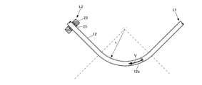
- the master hose 12 and the return hose 13 have inclined portions 12d and 13d between the bent portions 12a and 13a and the HPU side fixed end portions 12c and 13c.
- the inclined portions 12d and 13d are inclined with respect to a horizontal plane orthogonal to the direction of gravity. Specifically, the inclined parts 12d and 13d gradually incline upward from the HPU side fixed end parts 12c and 13c toward the bent parts 12a and 13a. Further, the inclination angle of the inclined portion 12d is set larger than the inclination angle of the inclined portion 13d.
- the HPU side fixed end 12c (see FIG. 2) fixed to the HPU 11 will be described as a clamp point L1
- the master side clamp portion 23 (see FIG. 3) of the second support member 22 will be described as a clamp point L2. That is, the master hose 12 is supported at the clamp point L1 and the clamp point L2.
- the bent portion 12a and the inclined portion 12d are disposed between the clamp point L1 and the clamp point L2.
- the clamp points L1 and L2 in the present embodiment correspond to a first clamp position and a second clamp position according to the present invention, respectively.
- the hydraulic fluid flows through the fluid passage 12e in the master hose 12 from the HPU 11 (see FIG. 2) toward the GSA 10 (in the direction indicated by the arrow A in the figure).
- the inclined portion 12d in front of the bent portion 12a is inclined upward at a predetermined inclination angle ⁇
- the hydraulic oil flowing in the fluid passage 12e in the master hose 12 is inclined to the inclined portion of the master hose 12. Collides with the inner wall of 12d. Due to the collision of the hydraulic oil with the inclined portion 12d, an impact force is generated in the vertical direction in the master hose 12. Since this impact force acts in the vertical direction of the master hose 12, the master hose 12 is elastically deformed in any of the vertical directions. For this reason, a single vibration is generated at an angular frequency ⁇ (rad / s) in the vertical direction ( ⁇ direction and ⁇ direction in the figure) of the master hose 12 by the impact force and the restoring force due to elastic deformation.
- the Coriolis force F c (N) is expressed as m (g), the fluid mass of hydraulic fluid flowing between the clamp point L1 and the clamp point L2, and the fluid angular velocity (corresponding to the angular frequency ⁇ of the single vibration).
- ⁇ (rad / s) and the flow velocity of hydraulic oil in the hose are V (m / s)
- equation (9) is obtained.
- the radius of curvature of the bent portion 12a of the master hose 12 is r (m)
- the fluid density is ⁇ (g / m 3 )
- the hydraulic fluid that flows between the clamp point L1 and the clamp point L2 When the flow rate, that is, the volume is v (m 3 ), the fluid angular velocity ⁇ and the fluid mass m in the above equation (9) are expressed by the following equations (10) and (11), respectively.
- the shape in which the bent portion 12a is included in a part of an ellipse has been described.
- the shape of the part may be sufficient.
- the curvature radius r (m) of the bent portion 12a is the curvature radius of a circle (not an ellipse) having a single curvature radius.
- the Coriolis force f c (t) per time is a sinusoidal excitation force that vibrates at the clamp points L1 and L2 with the amplitude F c and the angular frequency ⁇ , that is, a forced external force.
- the Coriolis force f c (t) per time is referred to as Coriolis forcing force f c (t).
- the grommet 25 of the master side clamp part 23 has the predetermined spring constant k and the predetermined damping coefficient h as described above, the vibration model of the damping forced vibration is applied particularly at the clamp point L2. Is done.
- equation (12) the equation of motion representing the vibration model of the damped forced vibration having the Coriolis forced force f c (t) as a forced external force is generally expressed by the following equation (13).
- M in the above formula (13) is the mass (g), that is, the fluid mass m (g) of the hydraulic fluid flowing between the clamp point L1 and the clamp point L2, and the hose mass of the master hose 12 between the clamps (g ) And the total mass (g).
- ⁇ n and ⁇ in the equation (14) are respectively defined by equations (20) and (21) described later.
- the solution x (t) of the above equation (14) is the sum of the general solution of free vibration with the right side in the above equation (13) set to 0 and the special solution x p (t) of steady vibration with respect to forced external force, It can represent with following Formula (15).
- the first term on the right side of the above equation (15) is a damped vibration of free vibration
- the second term on the right side is a harmonic vibration of forced vibration. That is, the solution x (t) becomes a transient vibration waveform in which free vibration and forced vibration are combined.
- the free vibration is eventually attenuated, and only the steady vibration represented by the special solution x p (t) representing the steady vibration remains.
- the special solution x p (t) is a harmonic response having the same frequency as the frequency of the forced external force.
- the Coriolis forcing force f c (t) in the above equation (13) is a sinusoidal excitation force as in the above equation (12), on the grommet 25 side of the master side clamp portion 23 that receives this, It responds at the same frequency as this sine wave excitation force. That is, the solution x p (t) in the above equation (16) is changed from the reaction force from the grommet 25 that changes with time according to the Coriolis forcing force f c (t), that is, the clamping reaction force f r (t) per time. And X indicating the amplitude in the above equation (16) is replaced with the amplitude F r of the clamping reaction force f r (t), the above equation (16) can be replaced by the following equation (17).
- the amplitude F r is a reaction force F r (N) with respect to the Coriolis force F c (N).
- ⁇ n in the above formulas (18) and (19) is the natural angular frequency of the grommet 25 and is represented by the following formula (20), and ⁇ is a so-called damping ratio, and the following formula (21 ).
- ⁇ / ⁇ n in the equations (20) and (21) is the amplitude of the Coriolis forcing force f c (t), that is, the angular frequency ⁇ of the Coriolis force F c and the natural angular frequency ⁇ n of the grommet 25.
- the magnitude of the clamping reaction force f r (t) near the resonance point is determined by the damping coefficient h.
- the damping coefficient h is doubled, the amplitude F r is increased.
- the peak is 1 ⁇ 2, and conversely, when the attenuation coefficient h is increased by 0.5, the peak of the amplitude F r is doubled.
- the magnitude of the clamping reaction force f r (t) near the resonance point that is, the amplitude F r can be adjusted by adjusting the damping coefficient h.
- the clamping reaction force f The magnitude of r (t) is determined by the spring constant k. That is, in the region ( ⁇ ⁇ ⁇ n ), the amplitude F r of the clamp reaction force f r (t) can be adjusted by adjusting the spring constant k.
- the clamping reaction force f r (t) applied from the grommet 25 to the master hose 12 according to the Coriolis forcing force f c (t) generated in the master hose 12 is pressed against the master hose 12.
- the Coriolis forcing force f c (t) generated in the master hose 12 and the clamping reaction force f r (t) applied to the master hose 12 are in phase with each other. And offset each other. That is, in the relational expression of the following expression (24), the Coriolis forcing force f c (t) and the clamp reaction force f r (t) are adjusted so that the value of ⁇ approaches 1.
- ⁇ is a coefficient used to establish the relational expression (24), that is, a reaction force recovery rate with respect to the generated Coriolis force F c (N), and a clamp reaction force f r (t) and determined by the ratio of the Coriolis forcing f c (t). Therefore, in this relational expression (24), if ⁇ is brought close to 1, as a result, the magnitude of the clamping reaction force f r (t) and the magnitude of the Coriolis forcing force f c (t) approximately match. means. Accordingly, as shown in FIG. 10, the Coriolis forcing force f c (t) and the clamping reaction force f r (t) work so as to cancel each other.
- the Coriolis force F c (N) is derived from the above equation (9), but the magnitude of the fluid mass in the equation (9) is changed by changing the value of m (g). Can be adjusted.
- the fluid mass m (g) is determined by the above equation (11), that is, the fluid density ⁇ (g / m 3 ) and the volume v (m 3 ).
- the fluid mass m (g) can be adjusted by adjusting the positions of the clamp point L1 and the clamp point L2. Therefore, it is possible to adjust the Coriolis force F c (N) by adjusting the fluid mass m (g). Adjusting the Coriolis force F c (N) leads to adjusting the amplitude of the Coriolis forced force f c (t) as a forced external force in the equation of motion of the damped forced vibration shown by the above equation (13).
- the positions of the clamp point L1 and the clamp point L2 are adjusted so that the Coriolis force F c (N), that is, the amplitude F c (N) of the Coriolis forcing force f c (t) is maximized.
- the clamp point L1 and the clamp point L2 are respectively arranged. Thereby, the Coriolis force F c (N) can be maximized.
- the angular frequency ⁇ of the Coriolis forcing force f c (t) is expressed by the above equation (10), the flow velocity V (m / s) of hydraulic oil in the hose or the radius of curvature of the bent portion 12a of the master hose 12. It depends on r (m). Therefore, in the present embodiment, the angular frequency ⁇ of the Coriolis forcing force f c (t) can be adjusted by adjusting the radius of curvature r (m) of the bent portion 12a.
- the Coriolis forcing force f c (t) is adjusted by adjusting the position of the clamp point L1, the clamp point L2, and the radius of curvature r (m) of the bent portion 12a of the master hose 12. can do.
- the clamping reaction force f r (t) is expressed by the above equation (17), and has a predetermined phase difference ⁇ obtained by the above equation (19) with respect to the Coriolis forcing force f c (t). Yes.
- the phase difference ⁇ is small as possible.
- the damping ratio ⁇ and the natural angular frequency ⁇ n of the grommet 25 in the equation (19) is adjusted.
- the adjustment of the damping ratio ⁇ and the natural angular frequency ⁇ n is performed by selecting or combining either or both of the spring constant k and the damping coefficient h of the grommet 25. Therefore, the grommet 25 having the optimum spring constant k and damping coefficient h is appropriately selected so that the phase difference ⁇ is as small as possible.
- the amplitude F r of the clamping reaction force f r (t) is expressed by the above equation (18), and the spring constant k and the damping coefficient h are determined by the selection of the grommet 25 in the adjustment of the phase difference ⁇ . And a predetermined size is determined.
- the amplitude F r of the clamping reaction force f r (t) also depends on the amplitude F c of the Coriolis forcing force f c (t) as shown in the above equation (18).
- the spring constant k and the damping coefficient h of the grommet 25 are adjusted so that the amplitude F r is maximized within the allowable phase difference ⁇ .
- the amplitude F r of the clamping reaction force f r (t) is considered in the case of ⁇ n ( ⁇ / ⁇ n ⁇ 1) close to the resonance point and the case of ⁇ ⁇ ⁇ n as described above.
- the above formula (22) and the above formula (23) may be determined by adjusting the damping coefficient h and the spring constant k of the grommet 25, respectively.
- the clamp reaction force f r (t) can be adjusted by adjusting the spring constant k and the damping coefficient h of the grommet 25.
- the clamp point L1 and the clamp point are set so that the Coriolis forcing force f c (t) and the clamp reaction force f r (t) cancel each other.
- the position of L2, the radius of curvature r (m) of the bent portion 12a of the master hose 12, the damping coefficient h of the grommet 25 and the spring constant k are each adjusted as appropriate.
- the clamping reaction force f r (t) acts to suppress the expansion amount of the master hose 12.
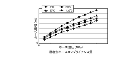
- the hose compliance amount of the master hose 12 will be described by comparing the conventional pipe support structure and the pipe support structure according to the present embodiment.
- the hose compliance amount by temperature shown in FIG. 11 shows the case where the conventional piping support structure is applied, and the horizontal axis shows hose hydraulic pressure (MPa) and the vertical axis shows hose expansion (ml). . Further, in the conventional pipe support structure, the master hose clamp point, the radius of curvature of the bent portion of the master hose, the grommet damping coefficient h, and the spring constant k are not optimized.
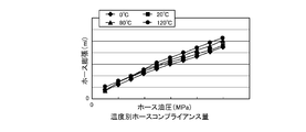
- the hose compliance amount for each temperature shown in FIG. 12 shows the case where the piping support structure according to the present embodiment is applied, and the positions of the clamp point L1 and the clamp point L2, the master hose 12
- the curvature radius r (m) of the bent portion 12a, the damping coefficient h of the grommet 25, and the spring constant k are adjusted as appropriate, and the Coriolis forcing force f c (t) and the clamping reaction force f r (t) are shown in FIG.
- it shows a case where it is optimized so as to have a canceling relationship.
- (Ml) converges to the amount of hose expansion (ml) at 0 ° C.
- the maximum is about 1 in comparison with the conventional piping support structure that expands about 1.5 times at the maximum according to the increase in the hose hydraulic pressure (MPa). It is possible to suppress the hose expansion amount to about 1 time.
- the piping support structure according to the present embodiment can suppress the hose expansion amount of the master hose 12 even when the temperature of the hydraulic oil rises.
- the piping support structure according to the present embodiment has the Coriolis force F c that is the amplitude of the Coriolis forcing force f c (t) generated in the master hose 12 when high-temperature hydraulic oil flows through the fluid passage 12e.
- the clamp point L1 and the clamp point so that the reaction force F r (N), which is the amplitude of the clamp reaction force f r (t) generated in the grommet 25 according to (N), acts to suppress the thermal expansion amount of the master hose 12.
- At least one position of L2 and the radius of curvature r (m) of the bent portion 12a are set, and the spring constant k and the damping coefficient h of the grommet 25 are set.
- the pipe support structure according to the present embodiment can use the generated Coriolis forcing force f c (t) and the clamping reaction force f r (t) generated in the grommet 25.
- the piping support structure according to the present embodiment maintains the degree of freedom of mounting unique to the master hose 12 made of an elastic member such as resin, for example, while maintaining the hose compliance amount in the high temperature range, that is, the master hose 12.
- the expansion amount can be suppressed with a simple and low-cost configuration.
- the piping support structure according to the present embodiment has a radius of curvature r (m) of the clamp point L1, the clamp point L2, and the bent portion 12a of the master hose 12 so that the coefficient ⁇ in the above equation (24) approaches 1.
- the spring constant k and the damping coefficient h of the grommet 25 are set. Therefore, the Coriolis forcing force f c (t) and the clamping reaction force f r (t) act so as to cancel each other. For this reason, the clamping reaction force f r (t) can be converted into a pressing load on the master hose 12, and the expansion amount of the master hose 12 can be suppressed.
- the piping support structure according to the present embodiment adjusts the fluid mass m (g) represented by the above equation (11) by adjusting the position of at least one of the clamp point L1 and the clamp point L2. .
- the Coriolis force F c (N) which is the amplitude of the Coriolis forcing force f c (t) is adjusted.
- the fluid angular velocity ⁇ (rad / s) represented by the above equation (10) is adjusted by adjusting the curvature radius r (m) of the bent portion 12 a.
- the piping support structure adjusts the Coriolis forcing force f c (t) only by adjusting the clamp point L1, the clamp point L2, and the curvature radius r (m) of the bent portion 12a. Can do.
- the phase difference ⁇ and the reaction force F r (N) are adjusted by adjusting the spring constant k and the damping coefficient h.
- the piping support structure according to the present embodiment can be selected by appropriately selecting the grommet 25 having the optimum spring constant k and damping coefficient h from the grommets having the different spring constant k and damping coefficient h.
- the clamping reaction force f r (t) can be adjusted according to the Coriolis forcing force f c (t).
- the support structure of the master hose 12 has been described.
- the support structure similar to the master hose 12 can be applied to the return hose 13.
- any piping can be applied as long as the piping is made of resin through which a fluid such as high-temperature hydraulic fluid flows and has a shape that generates Coriolis force.
- the present invention is suitably applied to piping in which hydraulic oil is used as a fluid and thermal expansion of the piping has an influence on hydraulic pressure control.
- the positions of the clamp point L1 and the clamp point L2, the radius of curvature r (m) of the bent portion 12a of the master hose 12, the damping coefficient h of the grommet 25, and the spring constant k are adjusted as appropriate.
- the Coriolis forcing force f c (t) and the clamping reaction force f r (t) are optimized so as to cancel each other as shown in FIG. position of the point L2, the radius of curvature r of the bent portion 12a of the master hose 12 (m), of the damping coefficient h and the spring constant k of the grommet 25, the Coriolis force force by adjusting at least any one f c (t ) And the clamping reaction force f r (t) may be optimized.
- the damping coefficient h and the spring constant k of the grommet 25 may be fixed, and the positions of the clamp point L1 and the clamp point L2 and the radius of curvature r (m) may be adjusted, or the clamp point L1 and the clamp point L2 may be adjusted.
- the position may be fixed and the damping coefficient h and the spring constant k of the grommet 25 may be adjusted.
- the Coriolis force F c (N) used in the present embodiment also depends on the flow velocity V (m / s) of the hydraulic oil in the hose, the flow velocity V (m / s) in the hose.
- the pipe support structure according to the present invention uses the generated Coriolis force and reaction force to maintain hose compliance in a high temperature range while maintaining the specific mounting flexibility of the resin pipe. It has an effect that the amount can be suppressed with a simple and low-cost configuration, and is useful for a general support structure for piping through which a high-temperature fluid flows.
Landscapes
- Engineering & Computer Science (AREA)
- General Engineering & Computer Science (AREA)
- Mechanical Engineering (AREA)
- Supports For Pipes And Cables (AREA)
- Measuring Volume Flow (AREA)
Abstract
発生するコリオリ力と反力とを利用して、樹脂製配管に特有の搭載自由度を維持しつつ、高温域におけるホースコンプライアンス量の抑制を簡単および低コストな構成で実現できる配管の支持構造を提供する。樹脂製のマスタホース(12)の支持構造であって、クランプ点(L1)、(L2)の少なくともいずれか一方において、マスタホース(12)を弾性的に保持するグロメットを備え、マスタホース(12)は、傾斜部と所定の曲率半径(r)を有する屈曲部(12a)とを、クランプ点(L1)、(L2)間に有し、グロメットは、所定のばね定数(k)および所定の減衰係数(h)を有し、マスタホース(12)に高温の作動油が流通したとき、マスタホース(12)に生ずるコリオリ力(Fc)に応じてグロメットに生ずる反力(Fr)がマスタホース(12)の熱膨張量の抑制に作用するよう、クランプ点(L1)、(L2)の位置および曲率半径(r)を設定するとともに、ばね定数(k)および減衰係数(h)を設定する。
Description
本発明は、配管の支持構造に関し、特に、高温の流体が流動する配管の支持構造に関する。
一般に、油圧で駆動制御されるアクチュエータ等の油圧機器には、配管を介して作動油が供給されるようになっている。このような油圧で駆動制御されるアクチュエータは、例えば自動車等の車両に搭載され、車両が有する種々の駆動装置の制御に用いられている。
従来、このようなアクチュエータなどの油圧機器を備えた車両として、ブレーキブースタによって作動するマスタシリンダと、マスタシリンダとホイールシリンダとの間に介在され、ホイールシリンダ側に加える油圧を制御する油圧ユニットと、マスタシリンダと油圧ユニットとを連結する配管とを含んで構成されたブレーキシステムを備えたものが知られている(例えば、特許文献1参照)。
この特許文献1に記載のブレーキシステムでは、マスタシリンダと油圧ユニットとを連結する配管が、金属製パイプと、この金属製パイプの中間部に形成された樹脂製ホースの外周に金属線をメッシュ状に被覆処理した可撓性ホースとから構成されている。このため、金属製パイプに比べて剛性が低い可撓性ホースを用いることにより、マスタシリンダと油圧ユニットとの相対位置の取付誤差に対応した配管形状の微調整を可能とし、また、油圧ユニットからマスタシリンダ側へ伝達され得る振動の吸収を可能としている。
ところで、上述のブレーキシステムなどの油圧システムに用いられる配管としては、車両への搭載自由度を考慮して、樹脂製の配管のみで構成されるものもある。このような樹脂製の配管を用いた油圧システムとして、例えば、図13に示すものがある。図13に示すように、この油圧システム100においては、油圧パワーユニット101とギヤシフトアクチュエータ102との間に、所定の曲率半径で屈曲した樹脂製配管103が用いられている。この樹脂製配管103は、任意の位置において支持部材105によりクランプされている。油圧パワーユニット101から出力された作動油は、樹脂製配管103を介してギヤシフトアクチュエータ102に供給される。
このような図13に示す樹脂製配管103にあっては、所定の曲率半径で屈曲するとともに、油圧パワーユニット101から屈曲部103aに向うに従い水平面に対して所定の角度で傾斜しているため、作動油が供給されると、その作動油の流動に応じて上下方向に振動する。このとき、振動する樹脂製配管103に作動油が流動すると、作動油の流動方向と直交する方向にいわゆるコリオリ力F(F=2mωV、m:流体質量、ω:流体角速度、V:配管内流速)が生ずる。一方で、樹脂製配管103は、このようなコリオリ力F(N)に対向するよう支持部材105から反力F´を受ける。上述したコリオリ力Fは、図14に示すように、樹脂製配管103内を流動する作動油の流量(ml/s)が増加、あるいは作動油の温度(℃)が上昇するにつれ、増大することが知られている。
樹脂製配管103に作用するコリオリ力Fおよび反力F´は、図15に示すように、時間の経過とともに変化する。しかし、図15からも明らかなように、コリオリ力Fと反力F´とは、互いに対向する成分ではあるが、その大きさが一致していない。つまり、時間の経過とともに、コリオリ力Fの大きさが反力F´の大きさを上回ったり、あるいは逆に反力F´の大きさがコリオリ力Fの大きさを上回ったりする状態が生ずる。ここで、例えばコリオリ力Fの大きさに対して反力F´の大きさが大きいと、樹脂製配管103が押しつぶされる状態となり、樹脂製配管103内を流動する作動油の流速が速まり、油圧が設定値以上に大きくなってしまう。このように、図13に示される樹脂製配管103にあっては、コリオリ力Fと反力F´のバランスが考慮されていないため、安定した油圧の供給を妨げる要因の1つとなっている。
一方で、油圧システム100に用いられる樹脂製配管103においては、その全てが樹脂製であるか、あるいはその一部が樹脂製であるかを問わず、樹脂製配管103内を流動する作動油の温度変化による配管の剛性変化が、ギヤシフトアクチュエータ102等の油圧機器の位置制御や応答性に影響を与える。例えば、樹脂製配管103内を流動する作動油の温度が上昇すると、樹脂製配管103の剛性が低下し、樹脂製配管103の膨張量、いわゆるホースコンプライアンス量が増加することとなる。これにより、樹脂製配管103内の油圧が低下し、特にギヤシフトアクチュエータ102等の油圧機器の応答性が悪化するなどの不具合が生ずる。
このような作動油の温度変化に起因した樹脂製配管103の剛性変化は、ギヤシフトアクチュエータ102等の油圧機器の制御目標値を可変とするような構成とする必要が生じ、油圧機器の制御を複雑化させる要因となっている。また、急激な樹脂製配管103の剛性低下は、油圧振動を引き起こす原因となり得る。
したがって、樹脂製配管103にあっては、適切なホースコンプライアンス量の制御が要求される。
従来、樹脂製の配管における適切なホースコンプライアンス量の制御を可能とするための方法として、センサ、クーラント、断熱材および温度環境制御を実行する電子制御ユニット(ECU:Electronic Control Unit)等を油圧システムに導入することにより、ハードおよびソフト面からホースコンプライアンス量の制御を実行するものや、樹脂製の配管に代えて金属製の配管を用いたり、あるいは樹脂製の配管に金属ブレードを追加する方法が挙げられる。
しかしながら、図13に示す樹脂製配管103にあっては、発生するコリオリ力Fと反力F´のバランスについて、なんら対策が講じられていないという問題があった。
また、作動油の温度変化に起因した樹脂製配管103の剛性変化への対策として、従来のハードおよびソフト面からホースコンプライアンス量の制御を実行するものにあっては、油圧システム自体の大型化や搭載性の悪化および複雑化によりコストが増大するという問題があった。
また、樹脂製配管103に代えて金属製の配管を用いた場合にあっては、配管の搭載自由度が失われるという問題があった。加えて、例えば加速Gによる荷重が樹脂製配管103に加わった場合や油圧パワーユニット101およびギヤシフトアクチュエータ102の組付誤差に応じて配管の位置を調整する場合には、その荷重を吸収することができず、過度な荷重が支持部材にかかるという問題があった。
さらに、樹脂製配管103に金属ブレードを追加した場合にあっては、作動油の温度上昇に伴うホースコンプライアンス量の増加を抑制するには不十分であるという問題があった。
本発明は、上述のような従来の問題を解決するためになされたもので、発生するコリオリ力と反力とを利用することにより、樹脂製の配管に特有の搭載自由度を維持しつつ、高温域におけるホースコンプライアンス量の抑制を簡単および低コストな構成で実現することができる配管の支持構造を提供することを目的とする。
本発明に係る配管の支持構造は、上記目的達成のため、第1クランプ位置および第2クランプ位置において支持されるとともに、高温の流体を流通させる流体通路が内部に形成され、かつ弾性材料で形成された配管の支持構造であって、前記第1クランプ位置および前記第2クランプ位置の少なくともいずれか一方において、前記配管の外周部を弾性的に保持する保持部材を備え、前記配管は、重力方向に直交する水平面に対して傾斜した傾斜部と所定の曲率半径を有する屈曲部とを、前記第1クランプ位置と前記第2クランプ位置との間に有し、前記保持部材は、所定のばね定数および所定の減衰係数を有し、前記流体通路に高温の流体が流通したとき、前記配管に生ずるコリオリ力に応じて前記保持部材に生ずる反力が前記配管の熱膨張量の抑制に作用するよう、前記第1クランプ位置および前記第2クランプ位置の少なくともいずれか一方の位置ならびに前記屈曲部の形状を設定するとともに、前記保持部材の前記ばね定数および前記減衰係数を設定する構成を有している。
この構成により、本発明に係る配管の支持構造は、流体通路に高温の流体が流通したとき、配管に生ずるコリオリ力に応じて保持部材に生ずる反力が配管の熱膨張量の抑制に作用するよう、第1クランプ位置および第2クランプ位置の少なくともいずれか一方の位置ならびに屈曲部の形状を設定するとともに、保持部材のばね定数および減衰係数を設定するようにした。このため、本発明に係る配管の支持構造は、発生するコリオリ力と保持部材に生ずる反力とを利用することができる。これにより、本発明に係る配管の支持構造は、例えば樹脂などの弾性部材から構成される配管に特有の搭載自由度を維持しつつ、高温域におけるホースコンプライアンス量、すなわち配管の膨張量の抑制が簡単および低コストな構成で実現される。
本発明に係る配管の支持構造は、好ましくは、上記の配管の支持構造において、前記コリオリ力をFc、前記流体通路を流通する流体の流体角速度をω、時間をtとしたとき、前記配管の振動に応じて時間的に変化するコリオリ強制力fc(t)は、fc(t)=Fcsinωtで表され、前記コリオリ力Fcに対して前記保持部材に生ずる前記反力をFr、前記保持部材に生じ、前記コリオリ強制力fc(t)に応じて時間的に変化するクランプ反力をfr(t)とすると、前記クランプ反力fr(t)は、fr(t)=Frsin(ωt-φ)で表され、前記クランプ反力fr(t)と前記コリオリ強制力fc(t)との比に応じて決定される係数をκとしたとき、次式(1)における係数κが1に近づくよう、前記第1クランプ位置、前記第2クランプ位置、前記屈曲部の形状、前記ばね定数および前記減衰係数を設定する構成を有する。

この構成により、本発明に係る配管の支持構造は、(1)式における係数κが1に近づくよう、第1クランプ位置、第2クランプ位置、屈曲部の形状、ばね定数および減衰係数を設定するようにしたので、コリオリ強制力fc(t)とクランプ反力fr(t)とが互いに相殺するように作用する。このため、クランプ反力fr(t)を配管への押し付け荷重に変換することができ、配管の膨張量を抑制することができる。
本発明に係る配管の支持構造は、より好ましくは、上記の配管の支持構造において、前記第1クランプ位置と前記第2クランプ位置との間の前記流体通路を流動する流体の流体質量をm、前記流体通路を流れる流体の流速をVとしたとき、前記コリオリ力Fcは、次式(2)で示され、

前記流体の流体密度をρ、前記第1クランプ位置と前記第2クランプ位置との間の前記流体通路を流動する流体の流量をv、前記屈曲部の曲率半径をrとしたとき、上記(2)式における流体質量mおよび前記流体角速度ωは、それぞれ次式(3)、(4)で示され、


前記第1クランプ位置と前記第2クランプ位置の少なくともいずれか一方の位置を調整し、上記(3)式で示される前記流体質量mを調整することにより、前記コリオリ強制力fc(t)における振幅である前記コリオリ力Fcを調整し、前記屈曲部の曲率半径rを調整することにより前記流体角速度ωを調整するようにした構成を有する。
この構成により、本発明に係る配管の支持構造は、第1クランプ位置と第2クランプ位置の少なくともいずれか一方の位置を調整することにより(3)式で示される流体質量mを調整する。これにより、コリオリ強制力fc(t)における振幅であるコリオリ力Fcが調整される。また、本発明に係る配管の支持構造は、屈曲部の曲率半径rを調整することにより(4)式で示される流体角速度ωが調整される。
したがって、本発明に係る配管の支持構造は、第1クランプ位置および第2クランプ位置、屈曲部の曲率半径rを調整するだけで、コリオリ強制力fc(t)を調整することができる。
本発明に係る配管の支持構造は、さらに好ましくは、上記の配管の支持構造において、前記保持部材の固有振動数をωn、減衰比をζ、前記ばね定数をkとしたとき、前記クランプ反力fr(t)における振幅を示す前記反力Frおよび位相差φは、それぞれ次式(5)、(6)で示され、


前記減衰係数をh、前記流体通路全体の流体質量と前記配管の質量の合計の質量をMとしたとき、上記(5)式および(6)式における前記固有角振動数ωn、減衰比ζは、それぞれ次式(7)、(8)で示され、


前記ばね定数kおよび前記減衰係数hを調整することにより、前記位相差φおよび前記反力Frを調整する構成を有する。
この構成により、本発明に係る配管の支持構造は、ばね定数kおよび減衰係数hを調整することにより位相差φおよび反力Frが調整される。このため、本発明に係る配管の支持構造は、それぞれ異なるばね定数kおよび減衰係数hを有する保持部材の中から最適なばね定数kおよび減衰係数hを有する保持部材を適宜選択するだけで、コリオリ強制力fc(t)に応じてクランプ反力fr(t)を調整することができる。
本発明によれば、発生するコリオリ力と反力とを利用することにより、樹脂製の配管に特有の搭載自由度を維持しつつ、高温域におけるホースコンプライアンス量の抑制を簡単および低コストな構成で実現することができる配管の支持構造を提供することができる。
以下、本発明の実施の形態について、図面を参照して説明する。
図1を参照して、本発明の実施の形態に係る配管の支持構造が適用される車両1について、説明する。まず、構成について説明する。
図1に示すように、車両1は、駆動源としての図示しないエンジンと、図示しないクラッチ機構と、AMT(Automated Manual Transmission)4と、を含んで構成されている。クラッチ機構とAMT4とは、図示しないトルクチューブを介して連結されている。
エンジンは、ガソリンあるいは軽油等の炭化水素系の燃料と空気との混合気を、図示しないシリンダの燃焼室内において燃焼させることにより動力を出力する公知の動力装置で構成されている。このエンジンは、燃焼室内で混合気の吸気、圧縮、燃焼および排気の一連の行程を繰り返し行うことにより、シリンダ内のピストンを往復動させて、ピストンと動力伝達可能に連結された図示しないクランクシャフトを回転させるようになっている。
クラッチ機構は、エンジンとAMT4との間に設けられる。クラッチ機構は、図示しないクラッチアクチュエータと、エンジンのクランクシャフトに接続されたフライホイールと、トルクチューブ内に回転可能に支持されたAMT4の入力軸と同期して回転するクラッチディスクとを有している。このクラッチ機構は、クラッチアクチュエータによってフライホイールとクラッチディスクとを係合あるいは解放することにより、エンジンの回転をAMT4に伝達する伝達状態と伝達を遮断する遮断状態とに切換えるようになっている。クラッチアクチュエータは、図示しない配管を介して後述するHPU11に接続されており、HPU11から供給される油圧に応じて、フライホイールとクラッチディスクとを係合あるいは解放するようになっている。
AMT4は、トランスアクスルケース4aと、車両1の前進走行状態において例えば1速~6速のギヤ段を形成する図示しないギヤユニットと、ギヤシフトアクチュエータ(Gear Shift Actuator:以下、単にGSAという)10と、油圧パワーユニット(Hydraulic Power Unit:以下、単にHPUという)11と、を含んで構成されている。ギヤユニットは、トランスアクスルケース4a内に収容されている。なお、ギヤユニットで形成されるギヤ段は、1速~6速に限定されるものではない。
AMT4は、変速段の変速操作を手動ではなく、GSA10を用いて自動的に行うものであり、クラッチ機構から入力された回転を自動的に変速して出力するよう構成されている。また、本実施の形態に係る車両1においては、AMT4における自動的な変速動作とともに、クラッチ機構の断続動作も自動的に行われるようになっている。
ギヤユニットには、AMT4の入力軸と同期して回転する図示しないカウンタ軸と、出力軸と、出力軸上に空転可能に接続された複数の歯車とが設けられている。出力軸上の複数の歯車は、カウンタ軸上の複数の歯車とそれぞれ常時噛み合っており、各歯車列のギヤ比に応じた回転数でAMT4の入力軸と同期して回転するようになっている。ギヤユニットでは、これら複数の歯車のうち、いずれかの歯車が図示しないシンクロメッシュ機構によって出力軸と同期させられることにより、ギヤユニットの変速比が運転者の要求する変速比に設定されるようになっている。
GSA10は、配管としてのマスタホース12およびリターンホース13を介してHPU11に接続されており、HPU11から供給される油圧に応じて、図示しないセレクトシャフトおよびフォークシャフトを作動させるようになっている。
AMT4では、セレクトシャフトの作動により、シンクロメッシュ機構によって同期させられる歯車、すなわち運転者の要求する変速比に対応する歯車が選択されるようになっている。また、AMT4では、フォークシャフトの作動により、シンクロメッシュ機構の図示しないスリーブが軸方向に移動させられることで、運転者の要求する変速比に対応する歯車が出力軸と同期するようになっている。これにより、ギヤユニットにおける変速が終了するようになっている。
HPU11は、図示しないリザーバタンクに貯留された流体としての作動油を吸い込み、吸い込んだ作動油を調圧して、クラッチアクチュエータおよびGSA10にそれぞれ供給するようになっている。
また、HPU11は、図示しない電子制御装置(Electronic Control Unit:以下、単にECUという)と電気的に接続されており、ECUから送信される制御信号に基づき制御される図示しないマスタソレノイド、クラッチソレノイド、シフトソレノイドおよびセレクトソレノイドなどの各種ソレノイドやアキュームレータなどの各種機器を備えている。HPU11は、ECUから送信される制御信号に基づき、上述の各種ソレノイドおよび各種機器が制御されることにより、クラッチアクチュエータおよびGSA10に、調圧された作動油をそれぞれ供給し、これらアクチュエータを作動するようになっている。
ECUは、例えばCPU、RAM、ROM、入出力インターフェース等を備えるマイクロコンピュータを含んで構成されており、CPUは、RAMの一時記憶機能を利用するとともにROMに予め記憶されたプログラムに従って信号処理を行うようになっている。
次いで、図2~図5を参照して、マスタホース12およびリターンホース13について説明する。
図2に示すように、マスタホース12およびリターンホース13は、樹脂製のホースで構成されており、車両後方側に位置する屈曲部12a、13aにより屈曲した状態でGSA10とHPU11とに接続されている。また、マスタホース12の内部には、流体通路12e(図7参照)が形成されている。リターンホース13についても、マスタホース12と同様、その内部に流体通路が形成されている。そして、これらマスタホース12の流体通路12e(図7参照)およびリターンホース13の流体通路を、GSA10を作動するための作動油が流動するようになっている。
また、以下においては、マスタホース12およびリターンホース13のGSA10に固定される端部を、それぞれGSA側固定端部12b、13bとし、HPU11に固定される端部を、それぞれHPU側固定端部12c、13cとして説明を行う。
図3に示すように、マスタホース12およびリターンホース13は、第1支持部材21および第2支持部材22を介してトランスアクスルケース4a(図1参照)にクランプされている。
第1支持部材21は、GSA側固定端部12b、13bからHPU側固定端部12c、13c側に所定の距離だけ離隔した位置において、トランスアクスルケース4a(図1参照)に固定されている。第1支持部材21は、例えばSPCなどの鋼鉄材料を含む金属材料からなり、マスタホース12およびリターンホース13との間に、図示しないグロメットが介装されている。このグロメットは、例えばクロロプレンゴム(CR)やクロロスルホン化ポリエチレンゴム(CSM)などの弾性材料で構成されている。グロメットは、その他、プラスチック材料で構成されていてもよい。
第2支持部材22は、第1支持部材21からHPU側固定端部12c、13c側に所定の距離だけ離隔した位置において、トランスアクスルケース4a(図1参照)に固定されている。第2支持部材22は、第1支持部材21と同様、例えばSPCなどの鋼鉄材料を含む金属材料で構成されている。
また、第2支持部材22は、マスタホース12をクランプするためのマスタ側クランプ部23と、リターン側クランプ部24とを有している。これら各クランプ部は、同様に構成されているため、マスタ側クランプ部23を例に説明する。
図4、図5に示すように、マスタ側クランプ部23は、マスタホース12との間に保持部材としてのグロメット25が介装されている。グロメット25は、マスタホース12の外周面を覆うよう円筒状に形成されている。また、グロメット25とマスタホース12との間には、所定のクリアランスが形成されている。なお、このクリアランスは、形成されていなくともよい。
このグロメット25は、例えばクロロプレンゴム(CR)やクロロスルホン化ポリエチレンゴム(CSM)などの弾性材料で構成されている。したがって、グロメット25は、マスタホース12を弾性的に支持するようになっている。
また、グロメット25は、所定のばね定数kおよび所定の減衰係数(グロメットヒステリシスともいう)hを有しており、これらばね定数kおよび減衰係数hは、後述するコリオリ強制力fc(t)とクランプ反力fr(t)との関係式により最適な値に設定されている。グロメット25は、その他、プラスチック材料で構成されていてもよい。
なお、本実施の形態においては、第1支持部材21および第2支持部材22の材質を金属材料としたが、これに限らず、例えばPA11、PA12などのポリアミド系樹脂材料としてもよい。
また、図6に示すように、マスタホース12およびリターンホース13は、屈曲部12a、13aとHPU側固定端部12c、13cとの間に傾斜部12d、13dを有している。この傾斜部12d、13dは、重力方向に直交する水平面に対して傾斜している。具体的には、傾斜部12d、13dは、HPU側固定端部12c、13cから屈曲部12a、13aに向うに従い、徐々に上方に傾斜している。また、傾斜部12dの傾斜角度は、傾斜部13dの傾斜角度より大きく設定されている。
次いで、図7~図9を参照して、マスタホース12を例に、マスタホース12に作用するコリオリ力Fc(N)について説明する。図7~図9では、マスタホース12および第2支持部材22などの各構成部材を模式的に示している。
以下においては、HPU11に固定されるHPU側固定端部12c(図2参照)をクランプ点L1、第2支持部材22のマスタ側クランプ部23(図3参照)をクランプ点L2として説明を行う。すなわち、マスタホース12は、上記クランプ点L1、クランプ点L2において支持される。また、上述の屈曲部12a、傾斜部12dは、これらクランプ点L1~クランプ点L2間に配置される。なお、本実施の形態における上記クランプ点L1、L2は、それぞれ本発明に係る第1クランプ位置、第2クランプ位置に相当する。
まず、図7に示すように、HPU11(図2参照)からGSA10に向けて(図中、矢印Aで示す方向)、マスタホース12内の流体通路12eを作動油が流動する。このとき、屈曲部12aの手前の傾斜部12dが所定の傾斜角度θで上方に向けて傾斜しているため、マスタホース12内の流体通路12eを流動する作動油は、マスタホース12の傾斜部12dの内壁に衝突する。この作動油の傾斜部12dへの衝突により、マスタホース12には、上下方向に衝撃力が発生する。この衝撃力は、マスタホース12の上下方向に作用するため、マスタホース12が上下方向のいずれかに弾性変形する。このため、上記衝撃力と、弾性変形による復元力とにより、マスタホース12の上下方向(図中、Φ方向および-Φ方向)に角振動数ω(rad/s)で単振動が生ずる。
そして、図8に示すように、上述のような単振動が生じているマスタホース12内の流体通路12eを、さらに作動油が図中、矢印Aで示す方向に流動すると、マスタホース12には、いわゆるコリオリ力Fc(N)が発生する。
具体的には、マスタホース12がΦ方向に振動したときには、屈曲部12aの上流側にあっては、流動する作動油がマスタホース12の下部に衝突にすることにより、図中、下方にコリオリ力Fc(N)が発生する。一方、屈曲部12aの下流側にあっては、流動する作動油がマスタホース12の上部に衝突することにより、図中、上方にコリオリ力Fc(N)が発生する。
これに対し、例えば上記作動油の流動方向と逆向きに作動油が流動した場合、すなわちリターンホース13の振動方向がΦ方向であって、GSA10(図2参照)からHPU11に向けてリターンホース13内を作動油が流動した場合には、図8に示されるコリオリ力Fc(N)は、逆向きとなる。
ここで、上記コリオリ力Fc(N)は、クランプ点L1~クランプ点L2間を流動する作動油の流体質量をm(g)、流体角速度(上記単振動の角振動数ωに相当)をω(rad/s)、作動油のホース内流速をV(m/s)としたとき、次式(9)で示される。

また、図9に示すように、マスタホース12の屈曲部12aの曲率半径をr(m)、流体密度をρ(g/m3)、クランプ点L1~クランプ点L2間を流動する作動油の流量、すなわち体積をv(m3)とすると、上記(9)式における流体角速度ωおよび流体質量mは、それぞれ次式(10)、(11)で示される。


ここで、図9に示す屈曲部12aの曲率半径r(m)は、一般的な楕円式において定義される長径を示す長軸と屈曲部12aを含む楕円との交点における任意の曲率半径である。つまり、一般的な楕円の方程式x2/a2+y2/b2=1における長軸の長さ(長径)2aを等分した距離、すなわちaが屈曲部12aの曲率半径r(m)とされる。
なお、本実施の形態においては、屈曲部12aが楕円の一部に含まれる形状について説明したが、これに限らず、例えば屈曲部12aが単一の曲率半径を有する円(楕円でない)の一部の形状であってもよい。この場合、屈曲部12aの曲率半径r(m)は、単一の曲率半径を有する円(楕円でない)の曲率半径とされる。
さらに、マスタホース12は、角振動数ωで振動しているため、時間当たりのコリオリ力fc(t)は、次式(12)で示すことができる。

したがって、時間当たりのコリオリ力fc(t)は、クランプ点L1、L2において、振幅Fc、角振動数ωで振動する正弦波加振力、すなわち強制外力となる。以下の説明においては、上記時間当たりのコリオリ力fc(t)をコリオリ強制力fc(t)という。
一方で、マスタ側クランプ部23のグロメット25は、上述の通り、所定のばね定数kおよび所定の減衰係数hを有しているため、特にクランプ点L2においては、減衰強制振動の振動モデルが適用される。
ここで、コリオリ強制力fc(t)を強制外力とする減衰強制振動の振動モデルを表す運動方程式は、一般的に次式(13)で表される。

ただし、上記式(13)におけるMは、質点(g)、すなわちクランプ点L1~クランプ点L2間を流動する作動油の流体質量m(g)と両クランプ間のマスタホース12のホース質量(g)との合計の質量(g)を表している。
次いで、上記(13)式の全体をMで割ると、次式(14)となる。

ただし、上記(14)式におけるωn、ζは、後述する(20)、(21)式でそれぞれ定義される。
上記(14)式の解x(t)は、上記(13)式における右辺を0と置いた自由振動の一般解と、強制外力に対する定常振動の特解xp(t)との和となり、次式(15)で表すことができる。

上記(15)式の右辺の第1項は、自由振動の減衰振動であり、右辺の第2項は、強制振動の調和振動である。すなわち、解x(t)は、自由振動と強制振動とが合わさった過渡振動波形となる。
ここで、上記解x(t)において、所定の時間が経過すると自由振動は、やがて減衰し、定常振動を表す特解xp(t)で表される定常振動のみが残る。このとき、特解xp(t)は、強制外力の振動数と同じ振動数の調和応答となる。
したがって、上記定常振動の解xp(t)は、次式(16)で示すことができる。

ここで、上記(13)式におけるコリオリ強制力fc(t)は、上記(12)式の通り、正弦波加振力であるから、これを受けるマスタ側クランプ部23のグロメット25側では、この正弦波加振力と同様の振動数で応答することとなる。すなわち、上記(16)式における解xp(t)を、コリオリ強制力fc(t)に応じて時間とともに変化するグロメット25からの反力、すなわち時間当たりのクランプ反力fr(t)と置き、また上記(16)式における振幅を示すXを、クランプ反力fr(t)の振幅Frと置くと、上記(16)式は、次式(17)に置き換えることができる。ここで、上記振幅Frは、コリオリ力Fc(N)に対する反力Fr(N)である。

このとき、上記(17)式におけるクランプ反力fr(t)の振幅Fr、位相差φは、それぞれ次式(18)、(19)のように表すことができる。


ここで、上記(18)、(19)式におけるωnは、グロメット25が有する固有角振動数であり、次式(20)で表され、ζは、いわゆる減衰比であり、次式(21)で表される。


ここで、上記(20)、(21)式におけるω/ωnは、コリオリ強制力fc(t)の振幅、すなわちコリオリ力Fcの角振動数ωとグロメット25の固有角振動数ωnとの比であり、この比が1、つまりω/ωn=1のとき、共振現象が生じる。
したがって、例えば、共振点に近いω≒ωn(ω/ωn≒1)のとき、上記(18)式におけるクランプ反力fr(t)の振幅Frは、近似的に次式(22)で示される。

つまり、上記(22)式で示されるように、共振点近くにおけるクランプ反力fr(t)の大きさは、上記減衰係数hによって決まり、例えば減衰係数hを2倍にすると振幅Frのピークは1/2となり、逆に減衰係数hを0.5倍にすると振幅Frのピークは2倍となる。このように、共振点近くの領域においては、減衰係数hを調整することにより共振点近くにおけるクランプ反力fr(t)の大きさ、すなわち振幅Frを調整することができる。
一方で、グロメット25の固有角振動数ωnに比べてコリオリ力Fcの角振動数ωが小さい領域(ω<<ωn)では、上記(10)式におけるクランプ反力fr(t)の振幅Frは、近似的に次式(23)で示される。

つまり、上記(23)式で示されるように、グロメット25の固有角振動数ωnに比べてコリオリ力Fcの角振動数ωが小さい領域(ω<<ωn)において、クランプ反力fr(t)の大きさは、上記ばね定数kによって決まる。すなわち、上記領域(ω<<ωn)にあっては、ばね定数kを調整することによりクランプ反力fr(t)の振幅Frを調整することができる。
ところで、一般に高温の作動油が流通する樹脂製のホースにあっては、ホース内を流通する作動油の温度が上昇すると、この温度上昇に伴って膨張してしまう。すなわち、ホースの膨張量を表す、いわゆるホースコンプライアンス量が増加してしまう。このようなホースコンプライアンス量の増加は、油圧機器の応答性の悪化などの不具合を招来する。
そこで、本実施の形態においては、マスタホース12に生ずるコリオリ強制力fc(t)に応じてグロメット25からマスタホース12に加わるクランプ反力fr(t)を、マスタホース12への押し付け荷重とすることで、マスタホース12内を高温の作動油が流動した際のマスタホース12のホース膨張を抑えるようになっている。
ここで、上記クランプ反力fr(t)をマスタホース12への押し付け荷重とすることができたとしても、マスタホース12に生ずるコリオリ強制力fc(t)の大きさとマスタホース12に加わるクランプ反力fr(t)の大きさとが従来のようにバラつきが生じて一致していない(図15参照)と、安定した油圧の供給が困難となってしまう。
そこで、本実施の形態においては、図10に示すように、マスタホース12に生ずるコリオリ強制力fc(t)とマスタホース12に加わるクランプ反力fr(t)とを、その位相を一致させるとともに、互いに相殺させるようになっている。すなわち、次式(24)の関係式において、κの値が1に近づくように、コリオリ強制力fc(t)とクランプ反力fr(t)とがそれぞれ調整される。

ここで、上記κは、上記関係式(24)を成立させるために用いられた係数、すなわち発生するコリオリ力Fc(N)に対する反力回収率であり、クランプ反力fr(t)とコリオリ強制力fc(t)との比によって定まる。したがって、この関係式(24)において、κを1に近づけることは、結果としてクランプ反力fr(t)の大きさとコリオリ強制力fc(t)の大きさとが近似的に一致することを意味する。これにより、図10に示すように、コリオリ強制力fc(t)とクランプ反力fr(t)とが互いに相殺するように働くこととなる。
上記関係式(24)を成立させ、コリオリ強制力fc(t)とクランプ反力fr(t)とを、図10に示すように互いの位相を略一致させるとともに、その大きさ(振幅)を相殺させるようにするため、本実施の形態においては、コリオリ強制力fc(t)およびクランプ反力fr(t)をそれぞれ最適な値に調整するようになっている。
コリオリ強制力fc(t)およびクランプ反力fr(t)のそれぞれの調整方法は、次の通りである。
上述してきたように、コリオリ力Fc(N)は、上記(9)式により導かれるが、同(9)式における流体質量をm(g)の値を変化させることにより、その大きさを調整することができる。具体的には、流体質量m(g)は、上記(11)式、すなわち流体密度ρ(g/m3)および体積v(m3)により決定される。このため、クランプ点L1とクランプ点L2との位置を調整することにより、上記流体質量m(g)を調整することができる。したがって、上記流体質量m(g)を調整することで、コリオリ力Fc(N)を調整することが可能となる。このコリオリ力Fc(N)を調整することは、上記(13)式で示される減衰強制振動の運動方程式における強制外力としてのコリオリ強制力fc(t)の振幅を調整することに繋がる。
本実施の形態では、クランプ点L1とクランプ点L2との位置を調整し、コリオリ力Fc(N)、すなわちコリオリ強制力fc(t)の振幅Fc(N)が最大となる位置に、クランプ点L1、クランプ点L2をそれぞれ配置する。これにより、コリオリ力Fc(N)を最大とすることができる。
また、コリオリ強制力fc(t)の角振動数ωは、上記(10)式で示される通り、作動油のホース内流速V(m/s)あるいはマスタホース12の屈曲部12aの曲率半径r(m)に依存して決定される。したがって、本実施の形態では、屈曲部12aの曲率半径r(m)を調整することにより、コリオリ強制力fc(t)の角振動数ωを調整することができる。
このように、本実施の形態においては、クランプ点L1、クランプ点L2の位置およびマスタホース12の屈曲部12aの曲率半径r(m)を調整することによってコリオリ強制力fc(t)を調整することができる。
一方、クランプ反力fr(t)は、上記(17)式で示されるが、コリオリ強制力fc(t)に対して上記(19)式で求められる所定の位相差φを有している。このため、図10に示すように、コリオリ強制力fc(t)とクランプ反力fr(t)との位相を一致させるためには、上記位相差φをできる限り小さくすることが好ましい。
具体的には、上記(19)式における減衰比ζおよびグロメット25の固有角振動数ωnの少なくともいずれか一方を調整する。減衰比ζおよび固有角振動数ωnの調整は、グロメット25のばね定数k、減衰係数hの双方、あるいはいずれか一方の選択または組合せにより行われる。したがって、上記位相差φをできる限り小さくするよう、最適なばね定数k、減衰係数hを有するグロメット25を適宜選択する。
これに対して、クランプ反力fr(t)の振幅Frは、上記(18)式で示され、上記位相差φの調整におけるグロメット25の選択により、ばね定数k、減衰係数hが決定され、所定の大きさに決定される。このとき、クランプ反力fr(t)の振幅Frは、上記(18)式でも示される通り、コリオリ強制力fc(t)の振幅Fcにも依存しているため、好ましくは、上記(18)式においてクランプ反力fr(t)の振幅Frとコリオリ強制力fc(t)の振幅Fcとが近似する(Fr≒Fc)のがよい。
クランプ反力fr(t)の振幅Frの調整は、例えば、許容される位相差φの範囲において、振幅Frが最大となるようグロメット25のばね定数k、減衰係数hがそれぞれ調整される。
また、クランプ反力fr(t)の振幅Frは、上述した通り、共振点に近いω≒ωn(ω/ωn≒1)の場合、およびω<<ωnの場合を考慮して、上記(22)式および上記(23)式で示される通り、それぞれグロメット25の減衰係数hならびにばね定数kを調整することによって、決定されるようにしてもよい。
このように、本実施の形態においては、グロメット25のばね定数k、減衰係数hを調整することによってクランプ反力fr(t)を調整することができる。
したがって、本実施の形態では、図10に示すように、コリオリ強制力fc(t)とクランプ反力fr(t)とが互いに相殺するような関係となるよう、クランプ点L1およびクランプ点L2の位置、マスタホース12の屈曲部12aの曲率半径r(m)、グロメット25の減衰係数hならびにばね定数kのそれぞれを適宜調整する。これにより、クランプ反力fr(t)がマスタホース12の膨張量の抑制に作用する。
ここで、図11、図12を参照して、マスタホース12のホースコンプライアンス量について、従来の配管の支持構造と本実施の形態に係る配管の支持構造とを比較して説明を行う。
図11に示される温度別のホースコンプライアンス量は、従来の配管の支持構造を適用した場合を示すもので、横軸にホース油圧(MPa)、縦軸にホース膨張(ml)をそれぞれ示している。また、従来の配管の支持構造は、マスタホースのクランプ点、マスタホースの屈曲部の曲率半径、グロメットの減衰係数hおよびばね定数kのそれぞれが最適化されていないものである。
これに対し、図12に示される温度別のホースコンプライアンス量は、本実施の形態に係る配管の支持構造を適用した場合を示すもので、クランプ点L1およびクランプ点L2の位置、マスタホース12の屈曲部12aの曲率半径r(m)、グロメット25の減衰係数hならびにばね定数kのそれぞれを適宜調整し、コリオリ強制力fc(t)とクランプ反力fr(t)とが図10に示すように相殺する関係となるよう最適化された場合を示すものである。
図11、図12に示すように、本実施の形態に係る配管の支持構造を適用した例では、従来の配管の支持構造に比べて、20℃、80℃および120℃のそれぞれにおけるホース膨張量(ml)が0℃におけるホース膨張量(ml)に収束している。特に、作動油の温度が120℃の場合には、ホース油圧(MPa)の増加に応じて最大で約1.5倍に膨張していた従来の配管の支持構造に比べて、最大で約1.1倍程度のホース膨張量に抑えることが可能となる。この結果が示すように、本実施の形態に係る配管の支持構造は、作動油の温度が上昇してもマスタホース12のホース膨張量を抑制することができる。
このように、本実施の形態に係る配管の支持構造は、流体通路12eに高温の作動油が流通したとき、マスタホース12に生ずるコリオリ強制力fc(t)の振幅であるコリオリ力Fc(N)に応じてグロメット25に生ずるクランプ反力fr(t)の振幅である反力Fr(N)がマスタホース12の熱膨張量の抑制に作用するよう、クランプ点L1およびクランプ点L2の少なくともいずれか一方の位置ならびに屈曲部12aの曲率半径r(m)を設定するとともに、グロメット25のばね定数kおよび減衰係数hを設定するようにした。
このため、本実施の形態に係る配管の支持構造は、発生するコリオリ強制力fc(t)とグロメット25に生ずるクランプ反力fr(t)とを利用することができる。これにより、本実施の形態に係る配管の支持構造は、例えば樹脂などの弾性部材から構成されるマスタホース12に特有の搭載自由度を維持しつつ、高温域におけるホースコンプライアンス量、すなわちマスタホース12の膨張量の抑制を簡単および低コストな構成で実現することができる。
また、本実施の形態に係る配管の支持構造は、上記(24)式における係数κが1に近づくよう、クランプ点L1、クランプ点L2、マスタホース12の屈曲部12aの曲率半径r(m)、グロメット25のばね定数kおよび減衰係数hを設定するようにした。このため、コリオリ強制力fc(t)とクランプ反力fr(t)とが互いに相殺するように作用する。このため、クランプ反力fr(t)をマスタホース12への押し付け荷重に変換することができ、マスタホース12の膨張量を抑制することができる。
また、本実施の形態に係る配管の支持構造は、クランプ点L1とクランプ点L2の少なくともいずれか一方の位置を調整することにより上記(11)式で示される流体質量m(g)を調整する。これにより、コリオリ強制力fc(t)における振幅であるコリオリ力Fc(N)が調整される。また、本実施の形態に係る配管の支持構造は、屈曲部12aの曲率半径r(m)を調整することにより上記(10)式で示される流体角速度ω(rad/s)が調整される。
したがって、本実施の形態に係る配管の支持構造は、クランプ点L1およびクランプ点L2、屈曲部12aの曲率半径r(m)を調整するだけで、コリオリ強制力fc(t)を調整することができる。
さらに、本実施の形態に係る配管の支持構造は、ばね定数kおよび減衰係数hを調整することにより位相差φおよび反力Fr(N)が調整される。このため、本実施の形態に係る配管の支持構造は、それぞれ異なるばね定数kおよび減衰係数hを有するグロメットの中から最適なばね定数kおよび減衰係数hを有するグロメット25を適宜選択するだけで、コリオリ強制力fc(t)に応じてクランプ反力fr(t)を調整することができる。
なお、本実施の形態では、マスタホース12の支持構造について説明を行ったが、リターンホース13についても、マスタホース12と同様の支持構造を適用可能である。
また、本実施の形態においては、GSA10とHPU11との間に接続されたマスタホース12およびリターンホース13に、本発明に係る配管の支持構造を適用した例について説明したが、これに限らず、高温の作動油などの流体が流通する樹脂製の配管であって、コリオリ力が生ずるような形状の配管であれば、いずれの配管にも適用可能である。特に、流体として作動油を用い、油圧の制御に対して配管の熱膨張が影響を与えるような配管に好適に適用される。
また、本実施の形態では、クランプ点L1およびクランプ点L2の位置、マスタホース12の屈曲部12aの曲率半径r(m)、グロメット25の減衰係数hならびにばね定数kのそれぞれを適宜調整して、コリオリ強制力fc(t)とクランプ反力fr(t)とが図10に示すように相殺する関係となるよう最適化するようにしたが、これに限らず、クランプ点L1およびクランプ点L2の位置、マスタホース12の屈曲部12aの曲率半径r(m)、グロメット25の減衰係数hならびにばね定数kのうち、少なくともいずれか1つを調整することによりコリオリ強制力fc(t)とクランプ反力fr(t)とを最適化するものであってもよい。例えば、グロメット25の減衰係数hおよびばね定数kを固定として、クランプ点L1およびクランプ点L2の位置および曲率半径r(m)を調整するようにしてもよいし、クランプ点L1およびクランプ点L2の位置を固定として、グロメット25の減衰係数hおよびばね定数kを調整するようにしてもよい。
また、この他、本実施の形態で利用するコリオリ力Fc(N)は、作動油のホース内流速V(m/s)にも依存することから、このホース内流速V(m/s)を制御することにより、発生するコリオリ力Fc(N)、コリオリ強制力fc(t)を調整するようにしてもよい。
以上説明したように、本発明に係る配管の支持構造は、発生するコリオリ力と反力とを利用することにより、樹脂製の配管に特有の搭載自由度を維持しつつ、高温域におけるホースコンプライアンス量の抑制を簡単および低コストな構成で実現することができるという効果を有し、高温の流体が流動する配管の支持構造全般に有用である。
12 マスタホース
12a、13a 屈曲部
12c、13c HPU側固定端部
12d、13d 傾斜部
12e 流体通路
13 リターンホース
22 第2支持部材
23 マスタ側クランプ部
24 リターン側クランプ部
25 グロメット
L1 クランプ点
L2 クランプ点
12a、13a 屈曲部
12c、13c HPU側固定端部
12d、13d 傾斜部
12e 流体通路
13 リターンホース
22 第2支持部材
23 マスタ側クランプ部
24 リターン側クランプ部
25 グロメット
L1 クランプ点
L2 クランプ点
Claims (4)
- 第1クランプ位置および第2クランプ位置において支持されるとともに、高温の流体を流通させる流体通路が内部に形成され、かつ弾性材料で形成された配管の支持構造であって、
前記第1クランプ位置および前記第2クランプ位置の少なくともいずれか一方において、前記配管の外周部を弾性的に保持する保持部材を備え、
前記配管は、重力方向に直交する水平面に対して傾斜した傾斜部と所定の曲率半径を有する屈曲部とを、前記第1クランプ位置と前記第2クランプ位置との間に有し、
前記保持部材は、所定のばね定数および所定の減衰係数を有し、
前記流体通路に高温の流体が流通したとき、前記配管に生ずるコリオリ力に応じて前記保持部材に生ずる反力が前記配管の熱膨張量の抑制に作用するよう、前記第1クランプ位置および前記第2クランプ位置の少なくともいずれか一方の位置ならびに前記屈曲部の形状を設定するとともに、前記保持部材の前記ばね定数および前記減衰係数を設定することを特徴とする配管の支持構造。 - 前記コリオリ力をFc、前記流体通路を流通する流体の流体角速度をω、時間をtとしたとき、前記配管の振動に応じて時間的に変化するコリオリ強制力fc(t)は、fc(t)=Fcsinωtで表され、
前記コリオリ力Fcに対して前記保持部材に生ずる前記反力をFr、前記保持部材に生じ、前記コリオリ強制力fc(t)に応じて時間的に変化するクランプ反力をfr(t)とすると、前記クランプ反力fr(t)は、fr(t)=Frsin(ωt-φ)で表され、
前記クランプ反力fr(t)と前記コリオリ強制力fc(t)との比に応じて決定される係数をκとしたとき、次式(1)における係数κが1に近づくよう、前記第1クランプ位置、前記第2クランプ位置、前記屈曲部の形状、前記ばね定数および前記減衰係数を設定することを特徴とする請求項1に記載の配管の支持構造。

- 前記第1クランプ位置と前記第2クランプ位置との間の前記流体通路を流動する流体の流体質量をm、前記流体通路を流れる流体の流速をVとしたとき、前記コリオリ力Fcは、次式(2)で示され、


前記屈曲部の曲率半径rを調整することにより前記流体角速度ωを調整するようにしたことを特徴とする請求項2に記載の配管の支持構造。 - 前記保持部材の固有振動数をωn、減衰比をζ、前記ばね定数をkとしたとき、前記クランプ反力fr(t)における振幅を示す前記反力Frおよび位相差φは、それぞれ次式(5)、(6)で示され、


Priority Applications (4)
| Application Number | Priority Date | Filing Date | Title |
|---|---|---|---|
| EP11818907.5A EP2623831B1 (en) | 2010-10-01 | 2011-08-18 | Pipe support structure |
| CN201180003393.6A CN102575798B (zh) | 2010-10-01 | 2011-08-18 | 配管的支持结构 |
| US13/392,203 US20130200247A1 (en) | 2010-10-01 | 2011-08-18 | Pipe support structure |
| US14/513,786 US9851023B2 (en) | 2010-10-01 | 2014-10-14 | Pipe support structure |
Applications Claiming Priority (2)
| Application Number | Priority Date | Filing Date | Title |
|---|---|---|---|
| JP2010223997A JP5267530B2 (ja) | 2010-10-01 | 2010-10-01 | 配管の支持構造 |
| JP2010-223997 | 2010-10-01 |
Related Child Applications (2)
| Application Number | Title | Priority Date | Filing Date |
|---|---|---|---|
| US13/392,203 A-371-Of-International US20130200247A1 (en) | 2010-10-01 | 2011-08-18 | Pipe support structure |
| US14/513,786 Continuation US9851023B2 (en) | 2010-10-01 | 2014-10-14 | Pipe support structure |
Publications (1)
| Publication Number | Publication Date |
|---|---|
| WO2012042731A1 true WO2012042731A1 (ja) | 2012-04-05 |
Family
ID=45892228
Family Applications (1)
| Application Number | Title | Priority Date | Filing Date |
|---|---|---|---|
| PCT/JP2011/004612 Ceased WO2012042731A1 (ja) | 2010-10-01 | 2011-08-18 | 配管の支持構造 |
Country Status (5)
| Country | Link |
|---|---|
| US (2) | US20130200247A1 (ja) |
| EP (1) | EP2623831B1 (ja) |
| JP (1) | JP5267530B2 (ja) |
| CN (1) | CN102575798B (ja) |
| WO (1) | WO2012042731A1 (ja) |
Cited By (1)
| Publication number | Priority date | Publication date | Assignee | Title |
|---|---|---|---|---|
| DE102016224611A1 (de) | 2016-12-09 | 2018-06-14 | Audi Ag | Brennstoffzellenaufbau und Verfahren zu dessen Herstellung |
Families Citing this family (3)
| Publication number | Priority date | Publication date | Assignee | Title |
|---|---|---|---|---|
| KR20150120355A (ko) * | 2013-02-22 | 2015-10-27 | 나베야 바이-테크 가부시키가이샤 | 커플링 |
| JP6799963B2 (ja) * | 2015-08-27 | 2020-12-16 | 株式会社ブリヂストン | 樹脂管、樹脂管の製造方法、及び配管構造 |
| US10005443B1 (en) | 2017-04-12 | 2018-06-26 | Teraflex, Inc. | Brake line anchor |
Citations (4)
| Publication number | Priority date | Publication date | Assignee | Title |
|---|---|---|---|---|
| JPS6238004Y2 (ja) * | 1983-10-14 | 1987-09-29 | ||
| JP2004125021A (ja) | 2002-09-30 | 2004-04-22 | Honda Motor Co Ltd | パイプの固定方法 |
| JP2006194433A (ja) * | 2004-12-17 | 2006-07-27 | Tokai Rubber Ind Ltd | 燃料輸送用のコネクタ付き樹脂チューブの組付構造及びこれに用いるコネクタ付き樹脂チューブ |
| JP2010151228A (ja) * | 2008-12-25 | 2010-07-08 | Ud Trucks Corp | 配線及び配管の支持構造 |
Family Cites Families (13)
| Publication number | Priority date | Publication date | Assignee | Title |
|---|---|---|---|---|
| JPH0638562B2 (ja) * | 1985-08-12 | 1994-05-18 | 日産自動車株式会社 | 車両用アンテナ |
| JP3226222B2 (ja) | 1991-04-05 | 2001-11-05 | 吉彦 杉山 | 流体を用いた構造物の安定化方法 |
| HU215143B (hu) * | 1993-08-03 | 1998-12-28 | MMG Automatika Művek Rt. | Eljárás és berendezés áramló közeg tömegáramának mérésére |
| US5546814A (en) * | 1994-10-26 | 1996-08-20 | The Foxboro Company | Parallel-flow coriolis-type mass flowmeter with flow-dividing manifold |
| NZ335414A (en) * | 1997-01-30 | 2000-10-27 | Fisher & Paykel | Dishwasher chamber having drain pump impeller with upper disc sealing against casing, and lower blade roots radially spaced from hub to allow air accumulation for priming |
| JP4538891B2 (ja) | 2000-04-17 | 2010-09-08 | 株式会社Ihi | 配管支持装置 |
| JP2003176762A (ja) * | 2001-09-27 | 2003-06-27 | Yamaha Motor Co Ltd | 燃料噴射エンジンの燃料ホース取付構造 |
| JP4176449B2 (ja) * | 2002-10-30 | 2008-11-05 | 本田技研工業株式会社 | 小型車両における燃料配管構造 |
| JP4565150B2 (ja) * | 2003-05-12 | 2010-10-20 | 独立行政法人産業技術総合研究所 | コリオリ流量計 |
| AU2004324097B2 (en) * | 2004-09-17 | 2010-01-21 | Emerson Electric Co. | Compensation method and apparatus for a coriolis flow meter |
| CN1789068A (zh) * | 2004-12-17 | 2006-06-21 | 东海橡胶工业株式会社 | 用于输送燃料的管道结构、适用在该管道结构中的用于输送燃料的树脂管及其生产方法 |
| US7806213B2 (en) | 2004-12-17 | 2010-10-05 | Tokai Rubber Industries, Ltd. | Piping structure for transporting a fuel |
| DE102008007742A1 (de) * | 2007-04-25 | 2008-11-06 | Krohne Ag | Coriolis-Massendurchflußmeßgerät |
-
2010
- 2010-10-01 JP JP2010223997A patent/JP5267530B2/ja not_active Expired - Fee Related
-
2011
- 2011-08-18 US US13/392,203 patent/US20130200247A1/en not_active Abandoned
- 2011-08-18 CN CN201180003393.6A patent/CN102575798B/zh not_active Expired - Fee Related
- 2011-08-18 WO PCT/JP2011/004612 patent/WO2012042731A1/ja not_active Ceased
- 2011-08-18 EP EP11818907.5A patent/EP2623831B1/en not_active Ceased
-
2014
- 2014-10-14 US US14/513,786 patent/US9851023B2/en not_active Expired - Fee Related
Patent Citations (4)
| Publication number | Priority date | Publication date | Assignee | Title |
|---|---|---|---|---|
| JPS6238004Y2 (ja) * | 1983-10-14 | 1987-09-29 | ||
| JP2004125021A (ja) | 2002-09-30 | 2004-04-22 | Honda Motor Co Ltd | パイプの固定方法 |
| JP2006194433A (ja) * | 2004-12-17 | 2006-07-27 | Tokai Rubber Ind Ltd | 燃料輸送用のコネクタ付き樹脂チューブの組付構造及びこれに用いるコネクタ付き樹脂チューブ |
| JP2010151228A (ja) * | 2008-12-25 | 2010-07-08 | Ud Trucks Corp | 配線及び配管の支持構造 |
Non-Patent Citations (1)
| Title |
|---|
| See also references of EP2623831A4 |
Cited By (1)
| Publication number | Priority date | Publication date | Assignee | Title |
|---|---|---|---|---|
| DE102016224611A1 (de) | 2016-12-09 | 2018-06-14 | Audi Ag | Brennstoffzellenaufbau und Verfahren zu dessen Herstellung |
Also Published As
| Publication number | Publication date |
|---|---|
| US9851023B2 (en) | 2017-12-26 |
| CN102575798B (zh) | 2014-03-12 |
| US20150026956A1 (en) | 2015-01-29 |
| EP2623831A4 (en) | 2014-06-18 |
| JP2012077847A (ja) | 2012-04-19 |
| EP2623831B1 (en) | 2015-10-07 |
| US20130200247A1 (en) | 2013-08-08 |
| EP2623831A1 (en) | 2013-08-07 |
| CN102575798A (zh) | 2012-07-11 |
| JP5267530B2 (ja) | 2013-08-21 |
Similar Documents
| Publication | Publication Date | Title |
|---|---|---|
| CN103732943B (zh) | 动态减振装置 | |
| US9797470B2 (en) | Torsional vibration damper and torsional vibration damping method | |
| CN104053926B (zh) | 车辆用振动降低装置 | |
| JP7000879B2 (ja) | 車両の制御装置 | |
| JP5267530B2 (ja) | 配管の支持構造 | |
| US11247659B2 (en) | Vehicle control apparatus | |
| CN106884979B (zh) | 带有离心振子减振器的动力传动系统的控制装置 | |
| WO2014039846A2 (en) | Active torque ripple rectifier | |
| US20130328323A1 (en) | Method and mechanism for starting an internal combustion engine | |
| KR101814649B1 (ko) | 차량용 구동 장치의 제어 장치 | |
| WO2007055144A1 (ja) | 内燃機関の制御装置 | |
| JP6636809B2 (ja) | トルクコンバータの制御装置 | |
| US9283946B2 (en) | Vehicle drive apparatus | |
| CN108291606B (zh) | 用于减小动力传动系统中的扭振的装置 | |
| US20190195298A1 (en) | Method For Transmitting And Dampening Torques | |
| JP6900829B2 (ja) | 車両の制御装置 | |
| JP2018135933A (ja) | 車両の制御装置 | |
| JP2018105345A (ja) | ジャダー発生判定装置 | |
| JP2016118290A (ja) | 車両用動力伝達制御装置 | |
| US12110940B1 (en) | Vibration mitigation in vehicle using gear clutch control | |
| JP6413739B2 (ja) | 車両用駆動装置 | |
| JP6660247B2 (ja) | 車両の変速機 | |
| JP2017072157A (ja) | トルクコンバータの制御装置 | |
| JP2007092835A (ja) | 発進クラッチの制御装置 | |
| JP2014137115A (ja) | 動力伝達装置の制御装置 |
Legal Events
| Date | Code | Title | Description |
|---|---|---|---|
| WWE | Wipo information: entry into national phase |
Ref document number: 201180003393.6 Country of ref document: CN |
|
| WWE | Wipo information: entry into national phase |
Ref document number: 13392203 Country of ref document: US Ref document number: 2011818907 Country of ref document: EP |
|
| 121 | Ep: the epo has been informed by wipo that ep was designated in this application |
Ref document number: 11818907 Country of ref document: EP Kind code of ref document: A1 |
|
| NENP | Non-entry into the national phase |
Ref country code: DE |