WO2012042974A1 - 情報提示装置、デジタルカメラ、ヘッドマウントディスプレイ、プロジェクタ、情報提示方法、情報提示プログラム - Google Patents
情報提示装置、デジタルカメラ、ヘッドマウントディスプレイ、プロジェクタ、情報提示方法、情報提示プログラム Download PDFInfo
- Publication number
- WO2012042974A1 WO2012042974A1 PCT/JP2011/062275 JP2011062275W WO2012042974A1 WO 2012042974 A1 WO2012042974 A1 WO 2012042974A1 JP 2011062275 W JP2011062275 W JP 2011062275W WO 2012042974 A1 WO2012042974 A1 WO 2012042974A1
- Authority
- WO
- WIPO (PCT)
- Prior art keywords
- information
- sight
- line
- information presentation
- persons
- Prior art date
- Legal status (The legal status is an assumption and is not a legal conclusion. Google has not performed a legal analysis and makes no representation as to the accuracy of the status listed.)
- Ceased
Links
Images





Classifications
-
- G—PHYSICS
- G06—COMPUTING OR CALCULATING; COUNTING
- G06T—IMAGE DATA PROCESSING OR GENERATION, IN GENERAL
- G06T19/00—Manipulating three-dimensional [3D] models or images for computer graphics
- G06T19/006—Mixed reality
-
- G—PHYSICS
- G06—COMPUTING OR CALCULATING; COUNTING
- G06T—IMAGE DATA PROCESSING OR GENERATION, IN GENERAL
- G06T15/00—Three-dimensional [3D] image rendering
- G06T15/10—Geometric effects
- G06T15/20—Perspective computation
-
- G—PHYSICS
- G06—COMPUTING OR CALCULATING; COUNTING
- G06T—IMAGE DATA PROCESSING OR GENERATION, IN GENERAL
- G06T19/00—Manipulating three-dimensional [3D] models or images for computer graphics
Definitions
- the present invention relates to an information presentation device, a digital camera, a head mounted display, a projector, an information presentation method, and an information presentation program.
- Augmented reality technology that superimposes and displays a virtual object on an image of a real space (captured image) taken by a camera has become widespread, and mobile phones and head-mounted displays (HMD) that employ this technology have appeared.
- HMD head-mounted displays
- An augmented reality providing apparatus that provides such an augmented reality generally displays an image that matches the user who has the augmented reality providing apparatus on a display unit.
- a virtual object to be superimposed on a captured image is determined according to the line of sight of a user wearing an HMD.
- the usage of the augmented reality providing device can be expanded.
- the market scale of augmented reality technology can be increased.
- Patent Document 2 describes a method of detecting a person included in a captured image and superimposing a costume CG on the person. According to this method, it is possible to display in consideration of a human being reflected in the camera of the augmented reality providing apparatus. However, in the method of Patent Document 2, since it is necessary to continuously superimpose CG on a moving person, the system configuration becomes complicated and cannot be used easily by general users.
- Patent Document 3 is a technique for displaying a person's CG in a virtual space, and is not related to the augmented reality providing apparatus.
- Patent Document 4 relates to a system that detects the position and orientation of a person's face and is not related to an augmented reality providing device.
- Patent Document 5 uses face positions and face orientations in a three-dimensional space to determine whether or not people are facing each other, assigns attribute values according to the determination results, and assigns unique values to each person.
- the ID and the attribute value are associated with each other and are not related to the augmented reality providing device.
- Patent Documents 1 to 5 cannot realize such a projector.
- Japanese Laid-Open Patent Publication No. 2005-174021 Japanese Unexamined Patent Publication No. 2009-289035 Japanese Unexamined Patent Publication No. 2000-331190 Japanese Unexamined Patent Publication No. 2007-026073 Japanese Unexamined Patent Publication No. 2010-044448
- the present invention has been made in view of the above circumstances, and an object thereof is to provide a highly convenient information presentation apparatus, information presentation method, and information presentation program.
- An information presentation apparatus is an information presentation apparatus that presents information to a person in a real space, and controls the information to be superimposed on a real space image captured by an image sensor and displayed on a display unit, or Detected by a control unit that performs control to project the information onto a predetermined position in the real space, a gaze detection unit that detects a gaze of a person included in the real space image captured by the imaging device, and the gaze detection unit. And an information presentation position determining unit that determines the superimposed position of the information or the predetermined position based on the line of sight.
- Each of the digital camera and the head mounted display of the present invention includes each unit of the information presentation device, the imaging device, and the display unit, and the control unit adds the real space image captured by the imaging device to the real space image. Control to superimpose information and display the information on the display unit is performed.
- the projector of the present invention includes each unit of the information presentation device and the image sensor, and the control unit performs control to project the information onto a predetermined position in the real space.
- the information presentation method of the present invention is an information presentation method for presenting information to a person in a real space, and controls the information to be superimposed on a real space image captured by an image sensor and displayed on a display unit, or Detected in a control step for performing control to project the information onto a predetermined position in the real space, a gaze detection step for detecting a gaze of a person included in a real space image captured by the imaging device, and the gaze detection step. And an information presentation position determining step for determining the superimposed position of the information or the predetermined position based on the line of sight.
- the information presentation program of the present invention is a program for causing a computer to execute each step of the information presentation method.
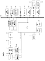
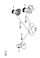
- the figure which shows schematic structure of the digital camera for describing one Embodiment of this invention Illustration for explaining a person's gaze vector 2 is a diagram for explaining a method for determining a superimposed position of a virtual object when three lines of sight illustrated in FIG. 2 are detected by the line-of-sight detection unit 12.
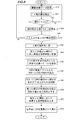
- movement at the time of the augmented reality mode of the digital camera shown in FIG. The figure which shows the 1st modification of the digital camera shown in FIG.
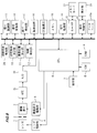
- movement at the time of the augmented reality mode of the digital camera shown in FIG. The figure which shows the 2nd modification of the digital camera shown in FIG.
- movement at the time of two person augmented reality mode of the digital camera shown in FIG. The flowchart for demonstrating operation
- FIG. 1 is a diagram showing a schematic configuration of a digital camera for explaining an embodiment of the present invention.
- This digital camera provides a user with augmented reality by superimposing and displaying information such as a virtual object (computer graphic; CG) on a real space image (captured image) obtained by photographing the real space. Equipped with augmented reality mode.
- CG computer graphic
- the imaging system of the digital camera shown in FIG. 1 includes a photographic lens 1 including a focus lens, a zoom lens, etc., a diaphragm 2 provided behind the photographic lens 1, a CCD type, a MOS type, etc. provided behind the diaphragm 2.
- the image pickup device 3 an analog front end (AFE) 32 that performs analog signal processing on the signal output from the image pickup device 3, an AD converter 33 that converts the output signal of the AFE 32 into digital output, and the focus lens of the shooting lens 1
- the lens drive unit 4 that controls the movement of the zoom lens and the image sensor drive unit 5 that controls the drive of the image sensor 3 are provided.
- the digital captured image signal output from the AD conversion unit 33 is output to the bus B.
- the lens drive unit 4, the image sensor drive unit 5, the AFE 32, and the AD conversion unit 33 are controlled by a system control unit (CPU) 6 that performs overall control of the entire digital camera.
- a system control unit (CPU) 6 that performs overall control of the entire digital camera.
- Connected to the CPU 6 are an operation unit 7 for performing various operations of the digital camera, a ROM 8 that stores various programs executed by the CPU 6, and a RAM 9 that is a work memory of the CPU 6.
- the CPU 6 is connected to the bus B.
- the electric control system of the digital camera shown in FIG. 1 includes a CPU 6, a superposition position determination unit 11, a line-of-sight detection unit 12, a coordinate conversion unit 14, a face part detection unit 15, a face detection unit 16, and a CG superposition unit. 17, a memory 18, a signal processing unit 19, a card interface 20 that controls a memory card (recording medium) 21, and a display control unit 22 that controls a display unit 23 such as a liquid crystal panel or an organic EL panel. These are connected to each other via a bus B and controlled by the CPU 6.
- the superposition position determination unit 11, the line-of-sight detection unit 12, the coordinate conversion unit 14, the face part detection unit 15, the face detection unit 16, and the CG superposition unit 17 are executed by the CPU 6, which is a computer, of an information presentation program stored in the ROM 8. It is a functional block realized by this.
- the signal processing unit 19 includes a digital signal processor (DSP), and performs image processing such as synchronization processing and ⁇ correction processing on the captured image signal output from the AD conversion unit 33 and temporarily stored in the memory 18. To generate captured image data.
- DSP digital signal processor
- the face detection unit 16 acquires the captured image data generated by the signal processing unit 19 and performs face detection processing on the acquired captured image data.
- the face part detection unit 15 detects the face parts detected by the face detection unit 16 (hereinafter, two eyes and a mouth as an example).
- the coordinate conversion unit 14 converts the coordinates of each point of the triangle on the two-dimensional plane that connects the center of each of the two eyes of the face detected by the face part detection unit 15 and the center of the mouth to the coordinates in the three-dimensional space ( World coordinate).
- the line-of-sight detection unit 12 detects a person's line of sight (a vector having a size and direction in a three-dimensional space) based on the triangular world coordinates converted by the coordinate conversion unit 14.
- the line-of-sight detection unit 12 calculates a normal vector of the triangle in a three-dimensional space starting from the midpoint between the points corresponding to the two eyes among the points of the triangle converted by the coordinate conversion unit 14.
- the normal vector is detected as a line of sight.
- the line-of-sight detection unit 12 has a triangular normal vector (line of sight) that connects the two eyes and mouth of each person.
- Vector B1 to B3 are calculated.
- the superposition position determination unit 11 calculates the center of gravity of the attention area in the three-dimensional space, which is the area where the plurality of lines of sight are focused, based on the plurality of lines of sight detected by the line of sight detection unit 12. Then, the superimposition position determination unit 11 determines the calculated barycentric position as a position (attention point) where the virtual object is to be superimposed.
- FIG. 3 is a diagram for explaining a method for determining the superimposed position of the virtual object when the three lines of sight B1 to B3 illustrated in FIG. 2 are detected by the line-of-sight detection unit 12.
- the superimposition position determination unit 11 is a line segment connecting the line-of-sight vector B1 and the line-of-sight vector B2 in the three-dimensional space defined by the world coordinates, and among the line segments perpendicular to both the line-of-sight vector B1 and the line-of-sight vector B2, The shortest line segment 3A is calculated.
- the superimposition position determination unit 11 calculates the shortest line segment 3B among the line segments connecting the line-of-sight vector B1 and the line-of-sight vector B3 and perpendicular to both the line-of-sight vector B1 and the line-of-sight vector B3.
- the superimposition position determination unit 11 calculates the shortest line segment 3C among the line segments connecting the line-of-sight vector B2 and the line-of-sight vector B3 and perpendicular to both the line-of-sight vector B2 and the line-of-sight vector B3.
- the superposition position determination unit 11 deletes the calculated line segments 3A to 3C having a length equal to or greater than the threshold value.
- the threshold When there is a line segment whose length is equal to or greater than the threshold, it can be determined that the two line-of-sight vectors connected by the line segment are greatly separated from each other. For this reason, such a line segment is not used for determining the position where the virtual object should be superimposed, thereby preventing a reduction in the calculation accuracy of the superimposed position of the virtual object.
- the overlapping position determination unit 11 selects a polygon that connects the midpoints of the three or more line segments as a region of interest. And the center of gravity of the region of interest is the coordinate on which the virtual object is superimposed.
- the overlapping position determination unit 11 determines whether the middle points of the two line segments are connected to each other. Let the point be the coordinate on which the virtual object is superimposed.
- the superimposition position determination unit 11 sets the midpoint of the one line segment as a coordinate for superimposing a virtual object. To do.
- the center of gravity of the triangle connecting the midpoint of the line segment 3A, the midpoint of the line segment 3B, and the midpoint of the line segment 3C are coordinates (attention point coordinates) on which the virtual object is superimposed.
- the CG superimposing unit 17 converts the attention point coordinates determined by the superimposition position determining unit 11 into two-dimensional coordinates, and generates augmented reality image data in which a predetermined virtual object is synthesized with the converted coordinates of the captured image data.
- the display control unit 22 is instructed to display an image based on the augmented reality image data on the display unit 23.
- the display control unit 22 causes the display unit 23 to display an image based on the augmented reality image data instructed from the CG superimposing unit 17.
- FIG. 4 is a flowchart for explaining the operation of the digital camera shown in FIG. 1 in the augmented reality mode.
- the CPU 6 controls the image sensor driving unit 5 to start moving image shooting by the image sensor 3.
- the signal processing unit 19 When moving image shooting is started by the image sensor 3, the signal processing unit 19 performs image processing on the captured image signals sequentially output from the image sensor 3, and generates captured image data.
- the generated captured image data is sequentially displayed on the display unit 23 under the control of the display control unit 22. Accordingly, the user can confirm the real space image being captured as a live view image.
- the face detection unit 16 acquires it (step S40), and executes face detection processing on the captured image data (step S41).
- step S42: Y When one or more faces are detected as a result of the face detection process (step S42: Y), the face part detection unit 15 detects two eyes and one mouth from the detected faces (step S42). S43). If one or more faces were not detected as a result of the face detection process (step S42: N), the process returns to step S40, the next frame of the moving image is acquired, and the face detection process is performed on this frame. .
- step S44: Y When the part group consisting of two eyes and mouths can be detected by two or more persons in the process of step S43 (step S44: Y), the processes after step S45 are performed. On the other hand, if two or more parts cannot be detected (step S44: N), the next frame of the moving image is acquired in step S40, and face detection processing is performed on this frame.
- step S45 the coordinate conversion unit 14 calculates the coordinates of each vertex of a triangle (part triangle) connecting the center of each of the two eyes and the center of the mouth for each part group detected in step S43.
- the coordinates are converted into coordinates in the three-dimensional space (world coordinates) (step S45).
- the line-of-sight detection unit 12 generates a normal vector (line-of-sight vector) of the part triangle starting from the midpoint of the line segment connecting the two eyes constituting the part triangle for each part triangle converted to world coordinates. ) Is calculated (step S46). At this point, N (N is a natural number of 2 or more) line-of-sight vectors are calculated.
- the superimposition position determination unit 11 is a line segment connecting one line-of-sight vector and each of the other (N ⁇ 1) line-of-sight vectors, and is perpendicular to both line-of-sight vectors.
- the process of calculating the shortest of these is performed for each of the N line-of-sight vectors. Thereby, [ ⁇ N (N-1) ⁇ / 2] line segments are calculated (step S47).
- the superposition position determination unit 11 deletes a line segment having a line segment length equal to or greater than the threshold TH from [ ⁇ N (N-1) ⁇ / 2] line segments (step S48). If all the line segments are deleted in step S48, the process proceeds to step S40. On the other hand, if one or more line segments remain in step S48, the process proceeds to step S49.
- step S49 if there are three or more remaining line segments, the superimposition position determination unit 11 uses the point of interest coordinates to superimpose the virtual object on the center of gravity of the polygon connecting the midpoints of the three line segments. And If there are two remaining line segments, the superimposition position determination unit 11 sets the midpoint of the line segment connecting the midpoints of the two line segments as the point-of-interest coordinates for superimposing the virtual object. . Further, if there is only one remaining line segment, the superimposition position determination unit 11 sets the midpoint of the one line segment as a target point coordinate on which the virtual object is superimposed.
- the CG superimposing unit 17 converts the point-of-interest coordinates calculated in step S49 into two-dimensional coordinates.
- the CG superimposing unit 17 generates augmented reality image data obtained by synthesizing a virtual object with the two-dimensional coordinates of the captured image data being displayed on the display unit 23, and displays an image based on the augmented reality image data as a display control unit.
- the information is displayed on the display unit 23 via 22 (step S50).
- step S50 When a still image shooting instruction is given via the operation unit 7 after step S50, the image pickup device 3 performs still image shooting, whereby the signal processing unit 19 generates captured image data. Then, the processing of step S40 to step S49 is performed, and the generated augmented reality image data is displayed on the display unit 23, and the augmented reality image data is recorded on the memory card 21 via the card interface 20.
- the superimposition position of the virtual object with respect to the real space image displayed on the display unit 23 can be determined according to the line of sight of the person photographed by the image sensor 3. For this reason, it is possible to provide augmented reality in consideration of the side to be photographed, and it is possible to widen the usage as an augmented reality providing device.
- this digital camera has a simple configuration that only detects the line of sight of a photographed person and determines the superimposed position of the virtual object according to the line of sight. For this reason, as described in Patent Document 2, there is a complicated system that uses a server computer that receives data from a portable display device and returns image data to be superimposed to the portable display device based on this data. It becomes unnecessary. Therefore, the technology of the present invention can be easily installed in a device such as a digital camera that can be easily purchased by general consumers.
- step S40 to step S50 is performed during live view image display before the still image shooting instruction is performed.
- this process may be performed only when a still image shooting instruction is issued.
- the digital camera calculates the coordinates of the attention point by performing the processing of steps S40 to S49 shown in FIG. 4 on the captured image data generated by the signal processing unit 19 after the photographing is completed. Thereafter, the digital camera generates augmented reality image data obtained by synthesizing the virtual object with the coordinates, displays the augmented reality image data on the display unit 23, and records the data on the memory card 21.
- the digital camera performs the processing shown in FIG. 4 on the captured image data recorded on the memory card 21 and the captured image data captured by another camera, and converts the augmented reality image data. It may be generated.
- this digital camera is premised on a method in which the photographer starts shooting after instructing with a finger or the like what area the subject person wants to pay attention to.
- FIG. 5 is a diagram showing a first modification of the digital camera shown in FIG.
- the digital camera shown in FIG. 5 has the same configuration as that shown in FIG. 1 except that a virtual object determination unit 10, a personal recognition unit 13, and a database 10a are added.
- the virtual object determination unit 10 and the individual recognition unit 13 are functional blocks realized by the CPU 6 executing the information presentation program.
- the personal recognition unit 13 detects a person from the captured image data generated by the signal processing unit 19 and determines the attribute of the person.
- a person attribute table in which a person image (face or whole image) is associated with an attribute of the person is recorded.
- the personal recognition unit 13 determines the attribute of the extracted person image based on the person image extracted from the captured image data and the person attribute table.
- the attribute of a person is information indicating at least one of gender, age, occupation, name, and clothes, for example.
- the virtual object determination unit 10 determines the contents of the virtual object based on the attribute discrimination result by the personal recognition unit 13 and the database 10a.
- a first table in which person attributes are associated with virtual object contents is recorded. This first table is provided for each person. When there are a plurality of persons, data indicating the contents of one virtual object is recorded for each attribute combination of the plurality of persons.
- FIG. 6 is a diagram showing an example of a first table (when there are three persons) recorded in the database 10a.
- a car is associated as a virtual object content for a combination of a 30-35 year old man, a 30-35 year old woman, and a 0-5 year old man.
- a doll is associated with the contents of the virtual object for a combination of a 30-35 year old man, a 30-35 year old woman, and a 0-5 year old woman.
- the contents of the virtual object are associated with soccer balls.
- the attributes of the three persons determined by the personal recognition unit 13 are 20-25 years old men wearing uniforms, 20-25 years old men wearing uniforms, and 20-25 years old wearing referee uniforms.
- the virtual object determination unit 10 determines the soccer ball as a virtual object according to the attribute and the database 10a.
- the image based on the augmented reality image data generated by the CG superimposing unit 17 looks like the image G shown in FIG. 7, and a virtual object highly correlated with the person being photographed is captured. Are superimposed on the area of interest.
- FIG. 8 is a flowchart for explaining the operation of the digital camera shown in FIG. 5 in the augmented reality mode.
- FIG. 5 the same processes as those in FIG.
- the personal recognition unit 13 When two or more eyes and mouths are detected in step S44, the personal recognition unit 13 performs personal recognition on the captured image data for which face detection has been performed in step S41, and a person included in the captured image data. Are determined (step S81).
- step S81 the processing of step S45 to step S49 is performed, and then the virtual object determination unit 10 determines a virtual object based on the attribute determined in step S81 and the database 10a (step S82).
- step S50 the CG superimposing unit 17 generates augmented reality image data in which the virtual object determined in step S82 is superimposed on the attention point determined in step S49. An image based on the data is displayed on the display unit 23.
- the contents of the virtual object to be superimposed on the real space image can be determined according to the attribute of the photographed person. For this reason, a virtual object can be made highly correlated with the person being photographed, and an augmented reality image without a sense of incongruity can be obtained even if the photographer does not specify the virtual object.
- FIG. 9 is a diagram showing a second modification of the digital camera shown in FIG.
- the digital camera shown in FIG. 9 has the same configuration as that shown in FIG. 5 except that a line-of-sight angle detection unit 24 is added.
- the digital camera shown in FIG. 9 has a two-person augmented reality mode on the assumption that there are two persons to be photographed.
- the line-of-sight angle detection unit 24 is a functional block realized by the CPU 6 executing the information presentation program.
- the line-of-sight angle detection unit 24 projects the two line-of-sight vectors detected by the line-of-sight detection unit 12 into a two-dimensional plane (a plane corresponding to the captured image) in the two-person augmented reality mode, and forms the projected two line-of-sight vectors.
- the angle ⁇ is calculated.
- the superimposition position determination unit 11 should convert the world coordinates of the intersection of the two gaze vectors detected by the gaze detection unit 12 into two-dimensional coordinates, and superimpose the two-dimensional coordinates on the CG. Determined as position (attention point).
- the superimposition position determining unit 11 determines the attention point according to the N line-of-sight vectors detected by the line-of-sight detection unit 12 as described above.
- the virtual object determination unit 10 determines the contents of the virtual object based on the angle ⁇ calculated by the line-of-sight angle detection unit 24 and the attributes of the two persons determined by the personal recognition unit 13. Determine (type and size).
- the attribute combinations of the two persons, the angle ⁇ formed by the line of sight of the two persons, and the contents (type and size) of the virtual object are associated with each other.
- a second table is recorded.
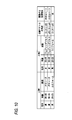
- FIG. 10 is a diagram showing an example of the second table recorded in the database 10a of the digital camera shown in FIG.
- a combination of a 20-25 year old man wearing a uniform and a 20-25 year old man wearing a uniform, 0 ⁇ ⁇ ⁇ ⁇ / 8 information, and “virtual” as the content of the virtual object are recorded in association with each other.
- the attribute determined by the personal recognition unit 13 is a combination of a 30-35 year old man wearing a tuxedo and a 30-35 year old woman wearing a wedding dress, and the angle calculated by the gaze angle detecting unit 24 When ⁇ is 30 degrees, as shown in FIG. 11A in FIG. 11, a small heart is superimposed and displayed near the intersection of the lines of sight of the two persons in the captured real space image.
- the attribute determined by the personal recognition unit 13 is a combination of a 30-35 year old man wearing a tuxedo and a 30-35 year old woman wearing a wedding dress, and is calculated by the gaze angle detecting unit 24.
- the angle ⁇ is 5 degrees, as shown in FIG. 11B in FIG. 11, a large heart is superimposed and displayed near the intersection of the lines of sight of the two persons in the captured real space image.
- the attribute determined by the personal recognition unit 13 is a combination of a 20-25 year old man wearing a uniform and a 20-25 year old man wearing a uniform, and is calculated by the gaze angle detection unit 24.
- the angle ⁇ is 5 degrees, as shown in FIG. 11C in FIG. 11, the flame is superimposed and displayed in the vicinity of the intersection of the two lines of sight in the captured real space image.
- FIG. 12 is a flowchart for explaining the operation of the digital camera shown in FIG. 9 in the two-person augmented reality mode.
- FIG. 12 the same processes as those in FIG.
- step S83 If the detection of the eyes and mouth of the two people is successful in the process of step S43 (step S110: Y), step S81, step S45, and step S46 are sequentially performed.
- the line-of-sight angle detection unit 24 projects the two line-of-sight vectors calculated in step S46 onto a two-dimensional plane (step S111), and calculates an angle ⁇ formed by the two projected line-of-sight vectors (step S112). ).
- the virtual object determination unit 10 performs virtual An object is determined (step S113).
- the superimposition position determination unit 11 calculates the intersection coordinates of the two line-of-sight vectors in the world coordinates calculated in step S46, and sets the intersection coordinates as the attention point.
- the CG superimposing unit 17 converts the intersection coordinates of the point of interest into two-dimensional coordinates, and generates augmented reality image data in which the virtual object determined in step S113 is synthesized with the converted intersection coordinates.
- An image based on the real image data is displayed on the display unit 23 (step S114).
- the type and size of the virtual object to be superimposed on the real space image according to the attributes of the two persons photographed and the angle formed by the line of sight. Can be determined.
- a virtual object in accordance with the feelings of two persons can be superimposed and displayed, providing an interesting augmented reality that reflects the intention of the person being photographed. be able to.
- the digital camera of the second modification may omit personal recognition in the two-person augmented reality mode.
- the user specifies a virtual object to be superimposed and displayed in the two-person augmented reality mode, and the virtual object determination unit 10 determines the specified virtual object according to the angle ⁇ calculated by the line-of-sight angle detection unit 24. The size of can be determined.
- a user designates a heart as a virtual object and shoots two people as shown in FIG. 11A in FIG. 11, when the angle of the line of sight of the two people is large, the heart becomes small as in FIG. When the line-of-sight angle is small, the heart becomes large as in FIG.
- the content (size) of the virtual object can be determined only according to the angle ⁇ formed by the line of sight.
- FIG. 13 is a flowchart for explaining a modification of the operation of the digital camera shown in FIG. 1 in the augmented reality mode.
- FIG. 13 the same processes as those in FIG. 13
- step S44 N
- coordinate conversion is performed.
- the unit 14 calculates the coordinates of each vertex of a triangle (part triangle) that connects the center of each of the two eyes detected in step S43 and the center of the mouth, and uses these coordinates as coordinates in the three-dimensional space (world coordinates). (Step S131).
- the line-of-sight detection unit 12 calculates a normal vector (line-of-sight vector) of the part triangle starting from the midpoint of the line segment connecting the two eyes constituting the part triangle converted into world coordinates (step) S132). At this point, one line-of-sight vector is calculated.
- the line-of-sight detection unit 12 acquires information on the line-of-sight vector of the image sensor 3 at the time of shooting to obtain the captured image data for which face detection has been performed in step S41 (step S133). Since the line-of-sight vector of the image sensor 3 coincides with the optical axis of the digital camera, the line-of-sight detection unit 12 calculates a straight line extending perpendicularly to the captured image data from the center of the captured image data as the line-of-sight vector of the image sensor 3. As a result, information on the line-of-sight vector of the image sensor 3 is acquired.
- the superimposition position determination unit 11 should superimpose a virtual object on the basis of the single line-of-sight vector calculated in step S132 and the line-of-sight vector of the image sensor 3 acquired in step S133 (attention point). ) Is determined (step S134).
- the superimposition position determination unit 11 is a line segment connecting one line-of-sight vector calculated in step S132 and the line-of-sight vector of the image sensor 3 acquired in step S133.
- the shortest of the vertical line segments is calculated, and the midpoint of the shortest line segment is determined as an attention point on which the virtual object is to be superimposed.
- step S50 the CG superimposing unit 17 generates augmented reality image data obtained by synthesizing a virtual object at the point of interest determined in step S134 of the captured image data, and an image based on the augmented reality image data. Is displayed on the display unit 23.
- the size of the virtual object may be changed according to the angle formed by the line-of-sight vector of one person and the line-of-sight vector of the image sensor 3.
- the augmented reality image data in consideration of the person to be photographed is generated, This can be provided to the user, and an unprecedented usage as an augmented reality providing device can be proposed.
- the augmented reality function is provided in the digital camera.
- the augmented reality function may be provided in the head mounted display (HMD).
- the person 14B and the person 14C are included in the image taken by the HMD image sensor 3 worn by the person 14A. Therefore, the augmented reality image G1 in which the virtual object is superimposed on the position corresponding to the line of sight of the person 14B and the person 14C in the real space image is displayed on the display unit 23 of the HMD worn by the person 14A.
- Images captured by the HMD image sensor 3 worn by the person 14B and the person 14C include only the person 14A. Therefore, the augmented reality image G2 in which the virtual object is superimposed on the position corresponding to the line of sight of the person 14A and the line of sight of the HMD worn by the person 14B is displayed on the display unit 23 of the HMD worn by the person 14B. Further, the HMD display unit 23 worn by the person 14C displays an augmented reality image G3 in which virtual objects are superimposed at positions corresponding to the line of sight of the person 14A and the line of sight of the HMD worn by the person 14C.
- the augmented reality function described in this embodiment can also be provided in a three-dimensional projector with an imaging device.
- FIG. 15 is a diagram showing a schematic configuration of a three-dimensional projector 150 for explaining an embodiment of the present invention.
- the block configuration shown in FIG. 15 is the block configuration of the digital camera shown in FIG. 1 except that the CG superimposing unit 17 is deleted and a projection unit 30 is provided instead of the display control unit 22 and the display unit 23. Is the same.
- a virtual space obtained by converting captured image data into world coordinates and a table for recording the position of the real space corresponding to the position of the virtual space are registered. Then, the superimposition position determination unit 11 reads out the position of the real space corresponding to the determined world coordinate of the target point from the table, and instructs the projection unit 30 to project the virtual object at the position of the real space.
- the projection unit 30 projects a virtual object at a position in the real space according to this instruction.
- the three-dimensional projector 150 detects the line of sight of the three persons included in the shot image, determines a point of interest according to the line of sight, A virtual object (soccer ball in the example of FIG. 16) is projected onto the real space position corresponding to the determined attention point.
- the part (lens 1, aperture 2, image sensor 3, AFE 32, AD conversion unit 33, lens drive unit 4, image sensor drive unit 5) where the 3D projector 150 performs imaging may be separated from the main body. .
- the part to be photographed can be arranged at a position where the person's line of sight can be easily detected, and the line of sight detection is facilitated.
- the CG superimposing unit 17 is deleted, the display control unit 22 and the display unit 23 are changed to the projecting unit 30, and the attention point determined by the superimposition position determining unit 11 is used. If the projection unit 30 is instructed to project a virtual object, a three-dimensional projector can be obtained. Further, the modified example described with reference to FIG. 13 can also be applied to the three-dimensional projector 150.
- the augmented reality function described in the present embodiment can also be realized by a commercially available computer.
- the program is read from a computer-readable medium (for example, CD-ROM, CD-R, DVD-ROM, DVD-R, USB memory, etc.) storing a program for executing each step of the flowchart shown in FIG. Install it on your computer.
- a computer-readable medium for example, CD-ROM, CD-R, DVD-ROM, DVD-R, USB memory, etc.
- the computer acquires captured image data designated by the user in step S40 shown in FIG. 4, and when the determination in step S42 is NO and the determination in step S44 is NO. If no line segment remains as a result of step S48, the user is notified that augmented reality image data cannot be generated, and the process is terminated.
- step S50 an image based on the augmented reality image data is displayed on a display unit connected to the computer.
- the computer is installed in a computer from a computer-readable medium storing a program for executing each step of the flowchart shown in FIG. 8 or FIG. 12, and the database 10a shown in FIG. Keep it.
- the computer executes this program, the computer acquires captured image data designated by the user in step S40 shown in FIGS. 8 and 12, and when the determination in step S42 is NO, and in steps S44 and S110.
- this determination is NO, the user is notified that augmented reality image data cannot be generated, and the process is terminated.
- step S50 and step S114 an image based on the augmented reality image data is displayed on the display unit connected to the computer.
- the program is installed in a computer from a computer-readable medium storing a program for executing each step of the flowchart shown in FIG.
- the computer executes this program, in step 40 shown in FIG. 13, the computer acquires captured image data designated by the user, and when the determination in step S42 is NO and the result of step S48 is a line segment. When no image remains, the user is notified that augmented reality image data cannot be generated, and the process ends.
- step S50 an image based on the augmented reality image data is displayed on a display unit connected to the computer.
- augmented reality image data can be generated and reproduced even on a commercially available computer having no imaging function.
- the disclosed information presentation device is an information presentation device that presents information to a person in a real space, and controls the information to be superimposed on a real space image captured by an image sensor and displayed on a display unit, or Detected by a control unit that performs control to project the information onto a predetermined position in the real space, a gaze detection unit that detects a gaze of a person included in the real space image captured by the imaging device, and the gaze detection unit. And an information presentation position determining unit that determines the superimposed position of the information or the predetermined position based on the line of sight.
- the disclosed information presentation apparatus determines the attributes of all persons whose eyes are detected using a database storing the images of the persons in association with the attributes and the images of all the persons.
- the apparatus further includes an attribute determination unit and an information content determination unit that determines the content of the information according to the attributes of all the persons.
- the attribute of the person indicates at least one of sex, age, occupation, name, and clothes.
- the disclosed information presentation device includes: an angle calculation unit that obtains an angle formed by each line of sight of two persons included in the real space image captured by the image sensor; and at least the information according to the angle formed by the line of sight And an information content determination unit for determining the content of the information.
- the disclosed information presentation apparatus determines the attributes of the two persons using a database in which the images of the two persons are associated with the attributes and the images of the two persons.
- the information content determination unit is further configured to determine the content of the information according to the angle formed by the line of sight and the attributes of the two persons.
- the attribute of the person indicates at least one of sex, age, occupation, name, and clothes.
- the disclosed information presentation apparatus further includes an imaging element line-of-sight information acquisition unit that acquires line-of-sight information of the imaging element when there is only one person included in the real space image captured by the imaging element,
- the information presentation position determination unit determines the superimposed position of the information or the predetermined position based on the line of sight of the one person and the line of sight of the image sensor.
- the disclosed digital camera includes each unit of the information presentation device, the imaging device, and the display unit, and the control unit superimposes the information on a real space image captured by the imaging device, and Control to be displayed on the display unit is performed.
- the disclosed head mounted display includes each unit of the information presentation device, the imaging device, and the display unit, and the control unit superimposes the information on a real space image captured by the imaging device. Control to display on the display unit is performed.
- the disclosed projector includes each unit of the information presentation device and the image sensor, and the control unit performs control to project the information onto a predetermined position in the real space.
- the disclosed information presentation method is an information presentation method for presenting information to a person in the real space, and controls the information to be superimposed on the real space image captured by the image sensor and displayed on the display unit, or Detected in a control step for performing control to project the information onto a predetermined position in the real space, a gaze detection step for detecting a gaze of a person included in a real space image captured by the imaging device, and the gaze detection step. And an information presentation position determining step for determining the superimposed position of the information or the predetermined position based on the line of sight.
- the disclosed information presentation method discriminates attributes of all persons whose eyes are detected using a database storing the images of the persons in association with the attributes and images of all the persons.
- the method further includes an attribute determination step and an information content determination step for determining the content of the information according to the attributes of all the persons.
- the attribute of the person indicates at least one of gender, age, occupation, name, and clothes.
- the information is calculated according to an angle calculation step for obtaining an angle formed by each line of sight of two persons included in the real space image captured by the image sensor, and at least according to the angle formed by the line of sight. And an information content determination step for determining the content of.
- the content of the information is determined according to the angle formed by the line of sight and the attributes of the two persons.
- the attribute of the person indicates at least one of gender, age, occupation, name, and clothes.
- the disclosed information presentation method further includes an imaging element line-of-sight information acquisition step of acquiring line-of-sight information of the imaging element when there is one person included in the real space image captured by the imaging element,
- the superimposed position of the information or the predetermined position is determined based on the direction of the line of sight of the one person and the direction of the line of sight of the image sensor.
- the disclosed information presentation program is a program for causing a computer to execute each step of the information presentation method.
Landscapes
- Engineering & Computer Science (AREA)
- Physics & Mathematics (AREA)
- Theoretical Computer Science (AREA)
- General Physics & Mathematics (AREA)
- Computer Graphics (AREA)
- Computer Hardware Design (AREA)
- General Engineering & Computer Science (AREA)
- Software Systems (AREA)
- Geometry (AREA)
- Computing Systems (AREA)
- Processing Or Creating Images (AREA)
- User Interface Of Digital Computer (AREA)
- Position Input By Displaying (AREA)
- Controls And Circuits For Display Device (AREA)
Abstract
利便性の高い情報提示装置を提供する。 情報提示装置としてのデジタルカメラは、撮像素子3で撮像された現実空間画像に仮想物体を重畳させて表示部23に表示させる制御を行うCG重畳部17と、撮像素子3で撮像された現実空間画像に含まれる人物の視線を検出する視線検出部12と、視線検出部12で検出された視線に基づいて、仮想物体の重畳位置を決定する重畳位置決定部11とを備える。
Description
本発明は、情報提示装置、デジタルカメラ、ヘッドマウントディスプレイ、プロジェクタ、情報提示方法、情報提示プログラムに関する。
カメラで撮影した現実空間の画像(撮像画像)に、仮想物体を重畳表示させる拡張現実技術が普及してきており、この技術を採用した携帯電話機やヘッドマウントディスプレイ(HMD)が登場してきている。
このような拡張現実感を提供する拡張現実感提供装置は、一般に、その拡張現実感提供装置を持っているユーザに合わせた映像を表示部に表示させている。例えば、特許文献1では、HMDを装着したユーザの視線に応じて、撮像画像に重畳させる仮想物体を決定している。
拡張現実感提供装置を持っているユーザに限らず、その拡張現実感提供装置のカメラに写っている人間のことも考慮した表示が可能になれば、拡張現実感提供装置の使い途を広げることができ、拡張現実技術の市場規模拡大を図ることができる。
例えば、特許文献2には、撮像画像に含まれる人物を検出し、その人物に衣装のCGを重畳させる方法が記載されている。この方法によれば、拡張現実感提供装置のカメラに写っている人間のことも考慮した表示が可能となる。しかし、特許文献2の方法は、動き回る人物にCGを重ね合わせ続ける必要があるため、システム構成が複雑になり、一般のユーザが気軽に利用することができない。
特許文献3は、仮想空間に人物のCGを表示させる技術であり、拡張現実感提供装置とは関係がない。
特許文献4は、人物の顔の位置と顔の向きを検出するシステムに関するものであり、拡張現実感提供装置とは関係がない。
特許文献5は、3次元空間上での顔位置と顔向きを用いて、人物間で互いに向き合っているか否かを決定し、その決定結果に応じて属性値を割り当て、それぞれの人物の固有のID及び属性値を紐付けるものであり、拡張現実感提供装置とは関係がない。
なお、拡張現実感提供装置に限らず、例えば、特定の位置に3次元映像を投影するプロジェクタにおいても、その映像を見る人物のことを考慮した投影が可能になれば、その使い途を広げることができる。特許文献1~5は、このようなプロジェクタを実現できるものではない。
本発明は、上記事情に鑑みてなされたものであり、利便性の高い情報提示装置、情報提示方法、及び情報提示プログラムを提供することを目的とする。
本発明の情報提示装置は、現実空間にいる人物に情報を提示する情報提示装置であって、撮像素子で撮像された現実空間画像に前記情報を重畳させて表示部に表示させる制御、又は、前記現実空間の所定位置に前記情報を投影させる制御を行う制御部と、前記撮像素子で撮像された現実空間画像に含まれる人物の視線を検出する視線検出部と、前記視線検出部で検出された視線に基づいて、前記情報の重畳位置又は前記所定位置を決定する情報提示位置決定部とを備えるものである。
本発明のデジタルカメラ及びヘッドマウントディスプレイは、それぞれ、前記情報提示装置の各部と、前記撮像素子と、前記表示部とを備え、前記制御部が、前記撮像素子で撮像された現実空間画像に前記情報を重畳させて前記表示部に表示させる制御を行うものである。
本発明のプロジェクタは、前記情報提示装置の各部と、前記撮像素子とを備え、前記制御部が、前記現実空間の所定位置に前記情報を投影させる制御を行うものである。
本発明の情報提示方法は、現実空間にいる人物に情報を提示する情報提示方法であって、撮像素子で撮像された現実空間画像に前記情報を重畳させて表示部に表示させる制御、又は、前記現実空間の所定位置に前記情報を投影させる制御を行う制御ステップと、前記撮像素子で撮像された現実空間画像に含まれる人物の視線を検出する視線検出ステップと、前記視線検出ステップで検出された視線に基づいて、前記情報の重畳位置又は前記所定位置を決定する情報提示位置決定ステップとを備えるものである。
本発明の情報提示プログラムは、前記情報提示方法の各ステップをコンピュータに実行させるためのプログラムである。
本発明によれば、利便性の高い情報提示装置、情報提示方法、及び情報提示プログラムを提供することができる。
以下、本発明の情報提示装置の一実施形態であるデジタルカメラについて図面を参照して説明する。
図1は、本発明の一実施形態を説明するためのデジタルカメラの概略構成を示す図である。このデジタルカメラは、現実空間を撮影して得た現実空間画像(撮像画像)に、仮想物体(コンピュータグラフィック;CG)等の情報を重畳させて表示することで、ユーザに拡張現実感を提供する拡張現実モードを搭載している。
図1に示すデジタルカメラの撮像系は、フォーカスレンズ、ズームレンズ等を含む撮影レンズ1と、撮影レンズ1後方に設けられた絞り2と、絞り2後方に設けられたCCD型、MOS型等の撮像素子3と、撮像素子3から出力される信号をアナログ信号処理するアナログフロントエンド(AFE)32と、AFE32の出力信号をデジタル変換して出力するAD変換部33と、撮影レンズ1のフォーカスレンズ、ズームレンズの移動制御を行うレンズ駆動部4と、撮像素子3の駆動制御を行う撮像素子駆動部5とを備える。AD変換部33から出力されたデジタルの撮像画像信号は、バスBに出力される。
レンズ駆動部4、撮像素子駆動部5、AFE32、及びAD変換部33は、デジタルカメラ全体を統括制御するシステム制御部(CPU)6によって制御される。CPU6には、デジタルカメラの各種操作を行うための操作部7と、CPU6が実行する各種プログラム等が格納されるROM8と、CPU6のワークメモリであるRAM9とが接続されている。また、CPU6はバスBに接続されている。
図1に示すデジタルカメラの電気制御系は、CPU6と、重畳位置決定部11と、視線検出部12と、座標変換部14と、顔パーツ検出部15と、顔検出部16と、CG重畳部17と、メモリ18と、信号処理部19と、メモリカード(記録媒体)21を制御するカードインターフェース20と、液晶パネルや有機ELパネル等の表示部23を制御する表示制御部22とを備え、これらがバスBを介して相互に接続され、CPU6によって制御される。
重畳位置決定部11、視線検出部12、座標変換部14、顔パーツ検出部15、顔検出部16、及びCG重畳部17は、ROM8に格納される情報提示プログラムをコンピュータであるCPU6が実行することで実現される機能ブロックである。
信号処理部19は、デジタルシグナルプロセッサ(DSP)で構成され、AD変換部33から出力されてメモリ18に一時記憶された撮像画像信号に対し、同時化処理、γ補正処理等の画像処理を施して撮像画像データを生成する。
顔検出部16は、信号処理部19で生成された撮像画像データを取得し、取得した撮像画像データに対し顔検出処理を施す。
顔パーツ検出部15は、顔検出部16で検出された顔のパーツ(以下では、一例として2つの目及び口とする)を検出する。
座標変換部14は、顔パーツ検出部15で検出された顔の2つの目の各々の中心と口の中心とを結ぶ二次元平面での三角形の各点の座標を、三次元空間の座標(世界座標)に変換する。
視線検出部12は、座標変換部14で変換後の三角形の世界座標に基づいて、人物の視線(三次元空間における大きさ及び方向を持ったベクトル)を検出する。
例えば、視線検出部12は、座標変換部14で変換された三角形の各点のうち、2つの目に対応する点同士の中点を始点とした三次元空間における当該三角形の法線ベクトルを算出し、この法線ベクトルを視線として検出する。図2に示すように、撮像画像データに3人の人物2A,2B,2Cが含まれていた場合、視線検出部12は、各人物の2つの目と口を結ぶ三角形の法線ベクトル(視線ベクトル)B1~B3を算出する。
重畳位置決定部11は、視線検出部12で検出された複数の視線に基づいて、当該複数の視線が注目している領域である三次元空間上の注目領域の重心を算出する。そして、重畳位置決定部11は、算出した重心位置を、仮想物体を重畳させるべき位置(注目点)として決定する。
図3は、図2に例示した3つの視線B1~B3が視線検出部12で検出されたときの仮想物体の重畳位置の決定方法を説明するための図である。
重畳位置決定部11は、世界座標で規定される三次元空間において、視線ベクトルB1と視線ベクトルB2を結ぶ線分であって、視線ベクトルB1と視線ベクトルB2の双方に垂直な線分のうち、最も短い線分3Aを算出する。
また、重畳位置決定部11は、視線ベクトルB1と視線ベクトルB3を結ぶ線分であって、視線ベクトルB1と視線ベクトルB3の双方に垂直な線分のうち、最も短い線分3Bを算出する。
また、重畳位置決定部11は、視線ベクトルB2と視線ベクトルB3を結ぶ線分であって、視線ベクトルB2と視線ベクトルB3の双方に垂直な線分のうち、最も短い線分3Cを算出する。
次に、重畳位置決定部11は、算出した線分3A~3Cのうち、長さが閾値以上のものを削除する。長さが閾値以上の線分が存在していた場合、その線分で結ばれる2つの視線ベクトル同士は大きく離れていると判断できる。このため、このような線分については、仮想物体を重畳させるべき位置の決定に用いないことで、仮想物体の重畳位置の算出精度の低下を防ぐ。
長さが閾値以上の線分を削除した結果、残った線分が3つ以上ある場合、重畳位置決定部11は、3つ以上の線分の各々の中点同士を結ぶ多角形を注目領域とし、この注目領域の重心を、仮想物体を重畳させる座標とする。
また、長さが閾値以上の線分を削除した結果、残った線分が2つである場合、重畳位置決定部11は、その2つの線分の各々の中点同士を結ぶ線分の中点を、仮想物体を重畳させる座標とする。また、長さが閾値以上の線分を削除した結果、残った線分が1つである場合、重畳位置決定部11は、その1つの線分の中点を、仮想物体を重畳させる座標とする。
図3に示すように、線分3A~3Cの長さが全て閾値未満の場合、線分3Aの中点と、線分3Bの中点と、線分3Cの中点とを結ぶ三角形の重心が、仮想物体を重畳させる座標(注目点座標)となる。
CG重畳部17は、重畳位置決定部11で決定された注目点座標を二次元座標に変換し、撮像画像データの当該変換後の座標に所定の仮想物体を合成した拡張現実画像データを生成し、この拡張現実画像データに基づく画像を表示部23に表示させる指示を、表示制御部22に対して行う。
表示制御部22は、CG重畳部17から指示された拡張現実画像データに基づく画像を、表示部23に表示させる。
以下では図1に示すデジタルカメラの拡張現実モード時の動作について説明する。図4は、図1に示したデジタルカメラの拡張現実モード時の動作を説明するためのフローチャートである。
拡張現実モードに設定されると、CPU6は、撮像素子駆動部5を制御して撮像素子3により動画撮影を開始させる。
撮像素子3により動画撮影が開始されると、撮像素子3から順次出力される撮像画像信号を信号処理部19が画像処理し、撮像画像データを生成する。生成された撮像画像データは、表示制御部22の制御により、表示部23に順次表示される。これにより、ユーザは、撮影中の現実空間画像をライブビュー画像として確認することができる。
一方、撮像画像データが生成されると、顔検出部16がこれを取得し(ステップS40)、当該撮像画像データに対して顔検出処理を実行する(ステップS41)。
顔検出処理の結果、1つ以上の顔が検出された場合(ステップS42:Y)は、顔パーツ検出部15が、検出された顔の中から目を2つと口を1つ検出する(ステップS43)。顔検出処理の結果、1つ以上の顔が検出されたかった場合(ステップS42:N)は、ステップS40に戻り、動画の次のフレームが取得され、このフレームに対して顔検出処理が行われる。
ステップS43の処理で、2つの目及び口からなるパーツ群を2人分以上検出できた場合(ステップS44:Y)は、ステップS45以降の処理が行われる。一方、パーツ群を2人分以上検出できなかった場合(ステップS44:N)は、ステップS40で動画の次のフレームが取得され、このフレームに対して顔検出処理が行われる。
ステップS45では、座標変換部14が、ステップS43で検出されたパーツ群毎に、2つの目の各々の中心と口の中心とを結ぶ三角形(パーツ三角形)の各頂点の座標を算出し、この座標を三次元空間の座標(世界座標)に変換する(ステップS45)。
次に、視線検出部12が、世界座標に変換後のパーツ三角形毎に、当該パーツ三角形を構成する2つの目を結ぶ線分の中点を始点とした当該パーツ三角形の法線ベクトル(視線ベクトル)を算出する(ステップS46)。この時点で、N本(Nは2以上の自然数)の視線ベクトルが算出される。
次に、重畳位置決定部11が、1本の視線ベクトルと、それ以外の(N-1)本の視線ベクトルの各々とを結ぶ線分であって、双方の視線ベクトルに垂直な線分のうち最短のものを算出する処理を、N本の視線ベクトルの各々について行う。これにより、[{N(N-1)}/2]本の線分が算出される(ステップS47)。
次に、重畳位置決定部11が、[{N(N-1)}/2]本の線分の中から、線分の長さが閾値TH以上の線分を削除する(ステップS48)。なお、ステップS48において全ての線分が削除された場合にはステップS40に処理が移行する。一方、ステップS48において線分が1つ以上残る場合にはステップS49に処理が移行する。
ステップS49では、重畳位置決定部11が、残った線分が3つ以上であれば、その3つの線分の各々の中点同士を結ぶ多角形の重心を、仮想物体を重畳する注目点座標とする。また、重畳位置決定部11は、残った線分が2つであれば、その2つの線分の各々の中点同士を結ぶ線分の中点を、仮想物体を重畳する注目点座標とする。また、重畳位置決定部11は、残った線分が1つであれば、その1つの線分の中点を、仮想物体を重畳する注目点座標とする。
次に、CG重畳部17が、ステップS49で算出された注目点座標を二次元座標に変換する。そして、CG重畳部17は、表示部23に表示中の撮像画像データの当該二次元座標に仮想物体を合成した拡張現実画像データを生成し、当該拡張現実画像データに基づく画像を、表示制御部22を介して表示部23に表示させる(ステップS50)。
ステップS50の後に操作部7を介して静止画撮影指示がなされた場合には、撮像素子3が静止画撮影を行い、これによって信号処理部19で撮像画像データが生成される。そして、ステップS40~ステップS49の処理が行われ、生成された拡張現実画像データが表示部23に表示されると共に、この拡張現実画像データがカードインターフェース20を介してメモリカード21に記録される。
以上のように、このデジタルカメラによれば、撮像素子3で撮影している人物の視線に応じて、表示部23に表示される現実空間画像に対する仮想物体の重畳位置を決定することができる。このため、撮影される側のことを考慮した拡張現実感を提供することができ、拡張現実感提供装置としての使い途を広げることができる。
また、このデジタルカメラは、撮影された人物の視線を検出し当該視線に応じて仮想物体の重畳位置を決めるだけの簡易な構成である。このため、特許文献2に記載のように、携帯型表示装置からデータを受信し、このデータを元に、重畳させる画像データを携帯型表示装置に返信するサーバーコンピュータを用いるような複雑なシステムが不要となる。したがって、デジタルカメラのように一般消費者にも手軽に購入できるような機器に本発明の技術を簡単に搭載することができる。
なお、以上の説明では、ステップS40からステップS50の処理を、静止画撮影指示が行われる前のライブビュー画像表示中に行っている。しかし、この処理を静止画撮影指示が行われたときだけ行ってもよい。
例えば、デジタルカメラは、撮影終了後、信号処理部19で生成した撮像画像データに対し、図4に示したステップS40~S49の処理を行って注目点の座標を算出する。その後、デジタルカメラは、この座標に仮想物体を合成した拡張現実画像データを生成し、これを表示部23に表示すると共に、これをメモリカード21に記録する。
この構成によれば、ライブビュー画像の表示中は図4に示すフローチャートの処理を行わずにすむため、デジタルカメラの消費電力の削減が可能となる。
また、デジタルカメラは、メモリカード21に記録されている撮影済みの撮像画像データや、別のカメラで撮影された撮像画像データに対し、図4に示した処理を行って、拡張現実画像データを生成してもよい。
このようにすることで、このデジタルカメラで撮影して得た撮像画像データに限らず、様々な撮像画像データを拡張現実画像データに変換することができ、デジタルカメラの付加価値を高めることができる。
なお、撮影される複数の人物が全く異なる方向を向いていては注目点を決定できなくなる。このため、このデジタルカメラでは、撮影者が、被写体となる人物にどのあたりを注目してもらいたいかを指等で指示してから撮影を開始するといった使い方を前提としている。
以下では、図1に示したデジタルカメラの変形例について説明する。
図5は、図1に示したデジタルカメラの第一の変形例を示す図である。図5に示したデジタルカメラは、仮想物体決定部10と個人認識部13とデータベース10aを追加した点を除いては、図1に示した構成と同じである。仮想物体決定部10と個人認識部13は、情報提示プログラムをCPU6が実行することで実現される機能ブロックである。
個人認識部13は、信号処理部19で生成された撮像画像データの中から人物を検出し、この人物の属性を判別する。
データベース10aには、人物の画像(顔又は全体像)とその人物の属性とを対応付けた人物属性テーブルが記録されている。個人認識部13は、撮像画像データの中から抽出した人物画像とこの人物属性テーブルとに基づいて、当該抽出した人物画像の属性を判別する。ここで、人物の属性とは、例えば性別、年齢、職業、名前、及び服装のうち少なくとも1つを示す情報である。
仮想物体決定部10は、個人認識部13による属性の判別結果とデータベース10aとに基づいて仮想物体の内容を決定する。
データベース10aには、人物の属性と仮想物体の内容とを対応付けた第一のテーブルが記録されている。この第一のテーブルは、人物の人数毎に設けられている。人物が複数の場合には、複数の人物の各々の属性の組み合わせに対して1つの仮想物体の内容を示すデータが記録されている。
図6は、データベース10aに記録される第一のテーブル(人物が3人の場合)の一例を示す図である。
図6に示すように、30-35歳の男、30-35歳の女、0-5歳の男の3人の組み合わせに対しては、仮想物体の内容としてクルマが対応付けられている。また、30-35歳の男、30-35歳の女、0-5歳の女の3人の組み合わせに対しては、仮想物体の内容として人形が対応付けられている。また、ユニフォームを着た20-25歳の男、ユニフォームを着た20-25歳の男、審判のユニフォームを着た20-25歳の男の3人の組み合わせに対しては、仮想物体の内容としてサッカーボールが対応付けられている。
例えば、個人認識部13で判別された3人の人物の属性が、ユニフォームを着た20-25歳の男、ユニフォームを着た20-25歳の男、審判のユニフォームを着た20-25歳の男であった場合、仮想物体決定部10は、この属性とデータベース10aにしたがって、サッカーボールを仮想物体として決定する。
この結果、CG重畳部17によって生成された拡張現実画像データに基づく画像は図7に示した画像Gのようになり、撮影されている人物に相関性の高い仮想物体が、撮影されている人物の注目している領域に重畳表示される。
図8は、図5に示したデジタルカメラの拡張現実モード時の動作を説明するためのフローチャートである。図5において図4と同じ処理には同一符号を付して説明を省略する。
ステップS44で二人以上の目と口の検出がなされた場合、個人認識部13が、ステップS41で顔検出がなされた撮像画像データに対して個人認識を行い、その撮像画像データに含まれる人物の属性を判別する(ステップS81)。
ステップS81の後は、ステップS45~ステップS49の処理が行われ、その後、仮想物体決定部10が、ステップS81で判別した属性とデータベース10aとに基づいて、仮想物体を決定する(ステップS82)。
ステップS82の後は、ステップS50にて、CG重畳部17が、ステップS82で決定された仮想物体を、ステップS49で決定した注目点に重畳させた拡張現実画像データを生成し、この拡張現実画像データに基づく画像を表示部23に表示させる。
以上のように、第一の変形例のデジタルカメラによれば、撮影された人物の属性に応じて、現実空間画像に重畳させる仮想物体の内容を決めることができる。このため、仮想物体を、撮影されている人物に相関性の高いものにすることができ、仮想物体を撮影者が指定しなくとも、違和感のない拡張現実画像を得ることができる。
図9は、図1に示したデジタルカメラの第二の変形例を示す図である。図9に示したデジタルカメラは、視線角度検出部24を追加した点を除いては、図5に示した構成と同じである。図9に示したデジタルカメラは、撮影対象となる人物が二人であることを前提とする二人拡張現実モードを有している。視線角度検出部24は、情報提示プログラムをCPU6が実行することで実現される機能ブロックである。
視線角度検出部24は、二人拡張現実モード時に、視線検出部12で検出された2つの視線ベクトルを二次元平面(撮像画像に対応する平面)に射影し、射影した2つの視線ベクトルのなす角度θを算出する。
重畳位置決定部11は、二人拡張現実モード時に、視線検出部12で検出された2つの視線ベクトルの交点の世界座標を二次元座標に変換し、当該二次元座標を、CGを重畳させるべき位置(注目点)として決定する。
二人拡張現実モード以外の拡張現実モードでは、重畳位置決定部11は、前述したように、視線検出部12で検出されたN本の視線ベクトルにしたがって注目点を決定する。
仮想物体決定部10は、二人拡張現実モード時に、視線角度検出部24で算出された角度θと、個人認識部13で判別された二人の人物の属性とに基づいて、仮想物体の内容(種類及び大きさ)を決定する。
図9に示すデジタルカメラにおけるデータベース10aには、二人の人物の属性の組み合わせと、当該二人の人物の視線のなす角度θと、仮想物体の内容(種類及び大きさ)とを対応付けた第二のテーブルが記録されている。
図10は、図9に示すデジタルカメラのデータベース10aに記録される第二のテーブルの一例を示す図である。
図10に示すように、タキシードを着た30-35歳の男とウエディングドレスを着た30-35歳の女の二人の組み合わせと、0≦θ≦π/8の情報と、仮想物体の内容として“大きなハート”とが対応付けて記録されている。
また、タキシードを着た30-35歳の男とウエディングドレスを着た30-35歳の女の二人の組み合わせと、π/8≦θ≦π/4の情報と、仮想物体の内容として“小さなハート”とが対応付けて記録されている。
また、ユニフォームを着た20-25歳の男とユニフォームを着た20-25歳の男の二人の組み合わせと、0≦θ≦π/8の情報と、仮想物体の内容として“炎”とが対応付けて記録されている。
例えば、個人認識部13で判別された属性が、タキシードを着た30-35歳の男とウエディングドレスを着た30-35歳の女の組み合わせであり、視線角度検出部24で算出された角度θが30度であった場合は、図11のFIG11Aに示すように、撮影された現実空間画像中の二人の視線の交点付近に、小さなハートが重畳表示される。
また、例えば、個人認識部13で判別された属性が、タキシードを着た30-35歳の男とウエディングドレスを着た30-35歳の女の組み合わせであり、視線角度検出部24で算出された角度θが5度であった場合は、図11のFIG11Bに示すように、撮影された現実空間画像中の二人の視線の交点付近に、大きなハートが重畳表示される。
また、例えば、個人認識部13で判別された属性が、ユニフォームを着た20-25歳の男とユニフォームを着た20-25歳の男の組み合わせであり、視線角度検出部24で算出された角度θが5度であった場合、図11のFIG11Cに示すように、撮影された現実空間画像中の二人の視線の交点付近に、炎が重畳表示される。
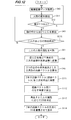
図12は、図9に示したデジタルカメラの二人拡張現実モード時の動作を説明するためのフローチャートである。図12において、図8と同じ処理には同一符号を付して説明を省略する。
ステップS43の処理で二人の目と口の検出が成功した場合(ステップS110:Y)は、ステップS81、ステップS45、ステップS46が順次行われる。
ステップS46の後、視線角度検出部24が、ステップS46で算出された2つの視線ベクトルを二次元平面に射影し(ステップS111)、射影した2つの視線ベクトルのなす角度θを算出する(ステップS112)。
次に、仮想物体決定部10が、ステップS81で判別された二人の人物の属性と、ステップS112で算出された角度θと、データベース10aに記録された第二のテーブルとに基づいて、仮想物体を決定する(ステップS113)。
次に、重畳位置決定部11が、ステップS46で算出された世界座標における2つの視線ベクトルの交点座標を算出し、この交点座標を注目点とする。
その後、CG重畳部17が、この注目点の交点座標を二次元座標に変換し、変換後の交点座標に、ステップS113で決定された仮想物体を合成した拡張現実画像データを生成し、この拡張現実画像データに基づく画像を表示部23に表示させる(ステップS114)。
なお、二人拡張現実モード以外の拡張現実モード時の動作は、図8で説明したとおりである。
以上のように、第二の変形例のデジタルカメラによれば、撮影された二人の人物の属性と視線のなす角度とに応じて、現実空間画像に重畳される仮想物体の種類及び大きさを決定することができる。このため、図11に示したように、二人の人物の気持ちに沿った仮想物体を重畳表示させることができ、撮影されている人物の意図を反映した、面白みのある拡張現実感を提供することができる。
なお、第二の変形例のデジタルカメラは、二人拡張現実モード時に個人認識を省略してもよい。この場合は、二人拡張現実モード時に重畳表示させる仮想物体をユーザが指定するものとし、仮想物体決定部10は、視線角度検出部24で算出された角度θに応じて、指定された仮想物体の大きさを決定すればよい。
例えば、ユーザは、仮想物体としてハートを指定して図11のFIG11Aに示すような二人を撮影すると、この二人の視線の角度が大きいときにはFIG11Aのようにハートが小さくなり、この二人の視線の角度が小さいときにはFIG11Bのようにハートが大きくなる。
このように、仮想物体が予め決まっている場合には、視線のなす角度θだけに応じて仮想物体の内容(大きさ)を決定することができる。
ここまでの説明では、撮像素子3で撮影された現実空間画像に人物が2人以上含まれているときに、人物の視線に応じた位置に仮想物体を重畳表示させるものとした。以下では、撮像素子3で撮影された現実空間画像に含まれる人物が1人のときでも、仮想物体を重畳表示する方法について説明する。
図13は、図1に示すデジタルカメラの拡張現実モード時の動作の変形例を説明するためのフローチャートである。図13において、図4と同じ処理には同一符号を付して説明を省略する。
ステップS43の処理の結果、撮像画像データに二人以上の目と口が検出されなかった場合、つまり、撮像画像データに人物が1人だけ含まれていた場合(ステップS44:N)、座標変換部14が、ステップS43で検出された2つの目の各々の中心と口の中心とを結ぶ三角形(パーツ三角形)の各頂点の座標を算出し、この座標を三次元空間の座標(世界座標)に変換する(ステップS131)。
次に、視線検出部12が、世界座標に変換後のパーツ三角形を構成する2つの目を結ぶ線分の中点を始点とした当該パーツ三角形の法線ベクトル(視線ベクトル)を算出する(ステップS132)。この時点で、1本の視線ベクトルが算出される。
次に、視線検出部12は、ステップS41で顔検出が行われた撮像画像データ、を得るための撮影時における撮像素子3の視線ベクトルの情報を取得する(ステップS133)。撮像素子3の視線ベクトルは、デジタルカメラの光軸と一致するため、視線検出部12は、撮像画像データの中心から当該撮像画像データに対して垂直に延びる直線を撮像素子3の視線ベクトルとして算出することで、撮像素子3の視線ベクトルの情報を取得する。
次に、重畳位置決定部11が、ステップS132で算出された1本の視線ベクトルと、ステップS133で取得された撮像素子3の視線ベクトルとに基づいて、仮想物体を重畳させるべき位置(注目点)を決定する(ステップS134)。
具体的には、重畳位置決定部11が、ステップS132で算出された1本の視線ベクトルとステップS133で取得された撮像素子3の視線ベクトルとを結ぶ線分であって、双方の視線ベクトルに対して垂直な線分のうち最短のものを算出し、この最短の線分の中点を、仮想物体を重畳させるべき注目点として決定する。
ステップS134の後は、ステップS50において、CG重畳部17が、撮像画像データのステップS134で決定された注目点に仮想物体を合成した拡張現実画像データを生成し、この拡張現実画像データに基づく画像を表示部23に表示させる。
以上のように、撮像素子3で撮影して得られた現実空間画像に人物が1人しか含まれない場合でも、その1人の人物の視線ベクトルと、撮像素子3の視線ベクトルとに基づいて、仮想物体を重畳させる位置を決定することができる。この場合、1人の人物の視線ベクトルと撮像素子3の視線ベクトルとのなす角度に応じて、仮想物体の大きさを変更してもよい。
このように、図1、図5、図9に示したデジタルカメラ、図13に示した動作を行うデジタルカメラによれば、撮影される人物のことを考慮した拡張現実画像データを生成して、これをユーザに提供することができ、拡張現実提供装置としてこれまでにない使い方を提案することができる。
なお、以上の説明ではデジタルカメラに拡張現実機能を設けるものとしたが、ヘッドマウントディスプレイ(HMD)に拡張現実機能を設けてもよい。
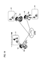
例えば、図1に示したブロック構成、又はその変形例の構成を持つHMDを、図14に示したように、3人の人物14A,14B,14Cが装着した場合を例にする。
この場合、人物14Aが装着するHMDの撮像素子3で撮影される画像には、人物14Bと人物14Cが含まれる。このため、人物14Aが装着するHMDの表示部23には、現実空間画像の人物14Bと人物14Cの視線に応じた位置に仮想物体が重畳された拡張現実画像G1が表示される。
人物14B,人物14Cが装着するHMDの撮像素子3で撮影される画像には、人物14Aのみが含まれる。このため、人物14Bが装着するHMDの表示部23には、人物14Aの視線と人物14Bが装着するHMDの視線とに応じた位置に仮想物体が重畳された拡張現実画像G2が表示される。また、人物14Cが装着するHMDの表示部23には、人物14Aの視線と人物14Cが装着するHMDの視線とに応じた位置に仮想物体が重畳された拡張現実画像G3が表示される。
このように、HMDに拡張現実機能を設けることで、撮影している側と、撮影されている側との双方で拡張現実感を共有することができる。
本実施形態で説明した拡張現実機能は、撮像装置付の三次元プロジェクタに設けることもできる。
図15は、本発明の一実施形態を説明するための三次元プロジェクタ150の概略構成を示す図である。図15に示すブロック構成は、CG重畳部17を削除し、表示制御部22及び表示部23の代わりに、投影部30を設けた点を除いては、図1に示したデジタルカメラのブロック構成と同じである。
三次元プロジェクタには、撮像画像データを世界座標に変換した仮想空間と、その仮想空間の位置に対応する現実空間の位置を記録するテーブルが登録されている。そして、重畳位置決定部11が、決定した注目点の世界座標に対応する現実空間の位置を当該テーブルから読み出し、当該現実空間の位置に仮想物体を投影するよう、投影部30に指示する。
投影部30は、この指示にしたがって、当該現実空間の位置に仮想物体を投影する。
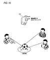
図16に示したように、三人の人物を撮影する場合、三次元プロジェクタ150は、撮影した画像に含まれる三人の人物の視線を検出し、この視線に応じて注目点を決定し、決定した注目点に対応する現実空間位置に仮想物体(図16の例ではサッカーボール)を投影する。
このようにすることで、撮影されている人達は、HMDを用いることなく、仮想物体を共有することができる。
なお、三次元プロジェクタ150の撮影を行う部分(レンズ1、絞り2、撮像素子3、AFE32、AD変換部33、レンズ駆動部4、撮像素子駆動部5)は、本体とは別体としてもよい。撮影を行う部分を別体にすることで、人物の視線を検出しやすい位置に撮影を行う部分を配置することができ、視線検出が容易になる。
また、図5,9に示したブロック構成においても、CG重畳部17を削除し、表示制御部22及び表示部23を投影部30に変更した構成とし、重畳位置決定部11が決定した注目点に仮想物体を投影するよう投影部30に指示する構成にすることで、三次元プロジェクタとすることができる。また、三次元プロジェクタ150においても、図13で説明した変形例を適用することができる。
本実施形態で説明した拡張現実機能は、市販のコンピュータによって実現することもできる。
例えば、図4に示したフローチャートの各ステップを実行するためのプログラムを記憶したコンピュータ可読媒体(例えば、CD-ROM、CD-R、DVD-ROM,DVD-R、USBメモリ等)から当該プログラムをコンピュータにインストールしておく。このプログラムをコンピュータが実行する場合、コンピュータは、図4に示すステップS40では、ユーザから指定された撮像画像データを取得し、ステップS42の判定がNOのときと、ステップS44の判定がNOのときと、ステップS48の結果、線分が1つも残らないときには、拡張現実画像データの生成ができないことをユーザに通知して、処理を終了する。また、ステップS50では、コンピュータに接続された表示部に、拡張現実画像データに基づく画像を表示させる。
又は、コンピュータに、図8又は図12に示したフローチャートの各ステップを実行するためのプログラムを記憶したコンピュータ可読媒体から当該プログラムをコンピュータにインストールし、図5又は図9に示したデータベース10aを内蔵しておく。このプログラムをコンピュータが実行する場合、コンピュータは、図8、図12に示すステップS40では、ユーザから指定された撮像画像データを取得し、ステップS42の判定がNOのときと、ステップS44、ステップS110の判定がNOのときには、拡張現実画像データの生成ができないことをユーザに通知して、処理を終了する。また、ステップS50、ステップS114では、コンピュータに接続された表示部に、拡張現実画像データに基づく画像を表示させる。
或いは、図13に示したフローチャートの各ステップを実行するためのプログラムを記憶したコンピュータ可読媒体から当該プログラムをコンピュータにインストールしておく。このプログラムをコンピュータが実行する場合、コンピュータは、図13に示すステップ40では、ユーザから指定された撮像画像データを取得し、ステップS42の判定がNOのときと、ステップS48の結果、線分が1つも残らないときには、拡張現実画像データの生成ができないことをユーザに通知して、処理を終了する。また、ステップS50では、コンピュータに接続された表示部に、拡張現実画像データに基づく画像を表示させる。
このように、撮像機能を持たない市販のコンピュータ上でも拡張現実画像データを生成して、これを再生することができる。
以上説明してきたように、本明細書には以下の事項が開示されている。
開示された情報提示装置は、現実空間にいる人物に情報を提示する情報提示装置であって、撮像素子で撮像された現実空間画像に前記情報を重畳させて表示部に表示させる制御、又は、前記現実空間の所定位置に前記情報を投影させる制御を行う制御部と、前記撮像素子で撮像された現実空間画像に含まれる人物の視線を検出する視線検出部と、前記視線検出部で検出された視線に基づいて、前記情報の重畳位置又は前記所定位置を決定する情報提示位置決定部とを備えるものである。
開示された情報提示装置は、前記視線が検出された全ての人物の属性を、前記人物の画像とその属性を対応付けて記録しているデータベースと前記全ての人物の画像とを用いて判別する属性判別部と、前記全ての人物の属性にしたがって、前記情報の内容を決定する情報内容決定部とを更に備えるものである。
開示された情報提示装置は、前記人物の属性は、性別、年齢、職業、名前、及び服装のうち少なくとも1つを示すものである。
開示された情報提示装置は、前記撮像素子で撮像された現実空間画像に含まれる二人の人物の各々の視線のなす角度を求める角度算出部と、少なくとも前記視線のなす角度にしたがって、前記情報の内容を決定する情報内容決定部とを更に備えるものである。
開示された情報提示装置は、前記二人の人物の属性を、前記二人の人物の画像とその属性を対応付けて記録しているデータベースと前記二人の人物の画像とを用いて判別する属性判別部を更に備え、前記情報内容決定部は、前記視線のなす角度と前記二人の人物の属性にしたがって、前記情報の内容を決定するものである。
開示された情報提示装置は、前記人物の属性は、性別、年齢、職業、名前、及び服装のうち少なくとも1つを示すものである。
開示された情報提示装置は、前記撮像素子で撮像された現実空間画像に含まれる人物が一人である場合に、前記撮像素子の視線の情報を取得する撮像素子視線情報取得部を更に備え、前記情報提示位置決定部は、前記一人の人物の視線と前記撮像素子の視線とに基づいて、前記情報の重畳位置又は前記所定位置を決定するものである。
開示されたデジタルカメラは、前記情報提示装置の各部と、前記撮像素子と、前記表示部とを備え、前記制御部が、前記撮像素子で撮像された現実空間画像に前記情報を重畳させて前記表示部に表示させる制御を行うものである。
開示されたヘッドマウントディスプレイは、前記情報提示装置の各部と、前記撮像素子と、前記表示部とを備え、前記制御部が、前記撮像素子で撮像された現実空間画像に前記情報を重畳させて前記表示部に表示させる制御を行うものである。
開示されたプロジェクタは、前記情報提示装置の各部と、前記撮像素子とを備え、前記制御部が、前記現実空間の所定位置に前記情報を投影させる制御を行うものである。
開示された情報提示方法は、現実空間にいる人物に情報を提示する情報提示方法であって、撮像素子で撮像された現実空間画像に前記情報を重畳させて表示部に表示させる制御、又は、前記現実空間の所定位置に前記情報を投影させる制御を行う制御ステップと、前記撮像素子で撮像された現実空間画像に含まれる人物の視線を検出する視線検出ステップと、前記視線検出ステップで検出された視線に基づいて、前記情報の重畳位置又は前記所定位置を決定する情報提示位置決定ステップとを備えるものである。
開示された情報提示方法は、前記視線が検出された全ての人物の属性を、前記人物の画像とその属性を対応付けて記録しているデータベースと前記全ての人物の画像とを用いて判別する属性判別ステップと、前記全ての人物の属性にしたがって、前記情報の内容を決定する情報内容決定ステップとを更に備えるものである。
開示された情報提示方法は、前記人物の属性は、性別、年齢、職業、名前、及び服装のうち少なくとも1つを示すものである。
開示された情報提示方法は、前記撮像素子で撮像された現実空間画像に含まれる二人の人物の各々の視線のなす角度を求める角度算出ステップと、少なくとも前記視線のなす角度にしたがって、前記情報の内容を決定する情報内容決定ステップとを更に備えるものである。
開示された情報提示方法は、前記二人の人物の属性を、前記二人の人物の画像とその属性を対応付けて記録しているデータベースと当該人物の画像とを用いて判別する属性判別ステップを更に備え、前記情報内容決定ステップでは、前記視線のなす角度と前記二人の人物の属性にしたがって、前記情報の内容を決定するものである。
開示された情報提示方法は、前記人物の属性は、性別、年齢、職業、名前、及び服装のうち少なくとも1つを示すものである。
開示された情報提示方法は、前記撮像素子で撮像された現実空間画像に含まれる人物が一人である場合に、前記撮像素子の視線の情報を取得する撮像素子視線情報取得ステップを更に備え、前記情報提示位置決定ステップでは、前記一人の人物の視線の方向と前記撮像素子の視線の方向とに基づいて、前記情報の重畳位置又は前記所定位置を決定するものである。
開示された情報提示プログラムは、前記情報提示方法の各ステップをコンピュータに実行させるためのプログラムである。
本発明によれば、利便性の高い情報提示装置、情報提示方法、及び情報提示プログラムを提供することができる。
本発明を詳細にまた特定の実施態様を参照して説明したが、本発明の精神と範囲を逸脱することなく様々な変更や修正を加えることができることは当業者にとって明らかである。
本出願は、2010年9月30日出願の日本出願(特願2010-223278)に基づくものであり、その内容はここに参照として取り込まれる。
本出願は、2010年9月30日出願の日本出願(特願2010-223278)に基づくものであり、その内容はここに参照として取り込まれる。
3 撮像素子
11 重畳位置決定部
12 視線検出部
17 CG重畳部
23 表示部
11 重畳位置決定部
12 視線検出部
17 CG重畳部
23 表示部
Claims (18)
- 現実空間にいる人物に情報を提示する情報提示装置であって、
撮像素子で撮像された現実空間画像に前記情報を重畳させて表示部に表示させる制御、又は、前記現実空間の所定位置に前記情報を投影させる制御を行う制御部と、
前記撮像素子で撮像された現実空間画像に含まれる人物の視線を検出する視線検出部と、
前記視線検出部で検出された視線に基づいて、前記情報の重畳位置又は前記所定位置を決定する情報提示位置決定部とを備える情報提示装置。 - 請求項1記載の情報提示装置であって、
前記視線が検出された全ての人物の属性を、前記人物の画像とその属性を対応付けて記録しているデータベースと、前記全ての人物の画像とを用いて判別する属性判別部と、
前記全ての人物の属性にしたがって、前記情報の内容を決定する情報内容決定部とを更に備える情報提示装置。 - 請求項2記載の情報提示装置であって、
前記人物の属性は、性別、年齢、職業、名前、及び服装のうち少なくとも1つを示す情報提示装置。 - 請求項1記載の情報提示装置であって、
前記撮像素子で撮像された現実空間画像に含まれる二人の人物の各々の視線のなす角度を求める角度算出部と、
少なくとも前記視線のなす角度にしたがって、前記情報の内容を決定する情報内容決定部とを更に備える情報提示装置。 - 請求項4記載の情報提示装置であって、
前記二人の人物の属性を、前記二人の人物の画像とその属性を対応付けて記録しているデータベースと、前記二人の人物の画像とを用いて判別する属性判別部を更に備え、
前記情報内容決定部は、前記視線のなす角度と前記二人の人物の属性にしたがって、前記情報の内容を決定する情報提示装置。 - 請求項5記載の情報提示装置であって、
前記人物の属性は、性別、年齢、職業、名前、及び服装のうち少なくとも1つを示す情報提示装置。 - 請求項1記載の情報提示装置であって、
前記撮像素子で撮像された現実空間画像に含まれる人物が一人である場合に、前記撮像素子の視線の情報を取得する撮像素子視線情報取得部を備え、
前記情報提示位置決定部は、前記一人の人物の視線と前記撮像素子の視線とに基づいて、前記情報の重畳位置又は前記所定位置を決定する情報提示装置。 - 請求項1~7のいずれか1項記載の情報提示装置の各部と、
前記撮像素子と、
前記表示部とを備え、
前記制御部が、前記撮像素子で撮像された現実空間画像に前記情報を重畳させて前記表示部に表示させる制御を行うデジタルカメラ。 - 請求項1~7のいずれか1項記載の情報提示装置の各部と、
前記撮像素子と、
前記表示部とを備え、
前記制御部が、前記撮像素子で撮像された現実空間画像に前記情報を重畳させて前記表示部に表示させる制御を行うヘッドマウントディスプレイ。 - 請求項1~7のいずれか1項記載の情報提示装置の各部と、
前記撮像素子とを備え、
前記制御部が、前記現実空間の所定位置に前記情報を投影させる制御を行うプロジェクタ。 - 現実空間にいる人物に情報を提示する情報提示方法であって、
撮像素子で撮像された現実空間画像に前記情報を重畳させて表示部に表示させる制御、又は、前記現実空間の所定位置に前記情報を投影させる制御を行う制御ステップと、
前記撮像素子で撮像された現実空間画像に含まれる人物の視線を検出する視線検出ステップと、
前記視線検出ステップで検出された視線に基づいて、前記情報の重畳位置又は前記所定位置を決定する情報提示位置決定ステップとを備える情報提示方法。 - 請求項11記載の情報提示方法であって、
前記視線が検出された全ての人物の属性を、前記人物の画像とその属性を対応付けて記録しているデータベースと、前記全ての人物の画像とを用いて判別する属性判別ステップと、
前記全ての人物の属性にしたがって、前記情報の内容を決定する情報内容決定ステップとを更に備える情報提示方法。 - 請求項12記載の情報提示方法であって、
前記人物の属性は、性別、年齢、職業、名前、及び服装のうち少なくとも1つを示す情報提示方法。 - 請求項11記載の情報提示方法であって、
前記撮像素子で撮像された現実空間画像に含まれる二人の人物の各々の視線のなす角度を求める角度算出ステップと、
少なくとも前記視線のなす角度にしたがって、前記情報の内容を決定する情報内容決定ステップとを更に備える情報提示方法。 - 請求項14記載の情報提示方法であって、
前記二人の人物の属性を、前記二人の人物の画像とその属性を対応付けて記録しているデータベースと当該人物の画像とを用いて判別する属性判別ステップを更に備え、
前記情報内容決定ステップでは、前記視線のなす角度と前記二人の人物の属性にしたがって、前記情報の内容を決定する情報提示方法。 - 請求項15記載の情報提示方法であって、
前記人物の属性は、性別、年齢、職業、名前、及び服装のうち少なくとも1つを示す情報提示方法。 - 請求項11記載の情報提示方法であって、
前記撮像素子で撮像された現実空間画像に含まれる人物が一人である場合に、前記撮像素子の視線の情報を取得する撮像素子視線情報取得ステップを更に備え、
前記情報提示位置決定ステップでは、前記一人の人物の視線の方向と前記撮像素子の視線の方向とに基づいて、前記情報の重畳位置又は前記所定位置を決定する情報提示方法。 - 請求項11~17のいずれか1項記載の情報提示方法の各ステップをコンピュータに実行させるための情報提示プログラム。
Priority Applications (4)
| Application Number | Priority Date | Filing Date | Title |
|---|---|---|---|
| JP2012536250A JP5337915B2 (ja) | 2010-09-30 | 2011-05-27 | 情報提示装置、デジタルカメラ、ヘッドマウントディスプレイ、プロジェクタ、情報提示方法、情報提示プログラム |
| CN201180047398.9A CN103140879B (zh) | 2010-09-30 | 2011-05-27 | 信息呈现装置、数字照相机、头戴式显示器、投影仪、信息呈现方法和信息呈现程序 |
| EP11828536.0A EP2624217A4 (en) | 2010-09-30 | 2011-05-27 | Information presentation device, digital camera, head mount display, projector, information presentation method, and information presentation program |
| US13/853,188 US9196093B2 (en) | 2010-09-30 | 2013-03-29 | Information presentation device, digital camera, head mount display, projector, information presentation method and non-transitory computer readable medium |
Applications Claiming Priority (2)
| Application Number | Priority Date | Filing Date | Title |
|---|---|---|---|
| JP2010223278 | 2010-09-30 | ||
| JP2010-223278 | 2010-09-30 |
Related Child Applications (1)
| Application Number | Title | Priority Date | Filing Date |
|---|---|---|---|
| US13/853,188 Continuation US9196093B2 (en) | 2010-09-30 | 2013-03-29 | Information presentation device, digital camera, head mount display, projector, information presentation method and non-transitory computer readable medium |
Publications (1)
| Publication Number | Publication Date |
|---|---|
| WO2012042974A1 true WO2012042974A1 (ja) | 2012-04-05 |
Family
ID=45892455
Family Applications (1)
| Application Number | Title | Priority Date | Filing Date |
|---|---|---|---|
| PCT/JP2011/062275 Ceased WO2012042974A1 (ja) | 2010-09-30 | 2011-05-27 | 情報提示装置、デジタルカメラ、ヘッドマウントディスプレイ、プロジェクタ、情報提示方法、情報提示プログラム |
Country Status (5)
| Country | Link |
|---|---|
| US (1) | US9196093B2 (ja) |
| EP (1) | EP2624217A4 (ja) |
| JP (1) | JP5337915B2 (ja) |
| CN (1) | CN103140879B (ja) |
| WO (1) | WO2012042974A1 (ja) |
Cited By (7)
| Publication number | Priority date | Publication date | Assignee | Title |
|---|---|---|---|---|
| JP2015197924A (ja) * | 2014-03-31 | 2015-11-09 | 三星電子株式会社Samsung Electronics Co.,Ltd. | 自動映像選択装置、自動映像選択方法、コンピュータ可読記録媒体及びコンピューティング装置 |
| CN105391938A (zh) * | 2014-08-27 | 2016-03-09 | 株式会社理光 | 图像处理装置、图像处理方法和计算机程序产品 |
| JP6040336B1 (ja) * | 2016-07-25 | 2016-12-07 | 株式会社オーエムアイ | 撮影対象位置特定装置、撮影対象位置特定方法、及びプログラム |
| JP2019080252A (ja) * | 2017-10-26 | 2019-05-23 | 株式会社リコー | プログラム、画像表示方法、画像表示システム、情報処理装置 |
| JP2020010327A (ja) * | 2018-07-10 | 2020-01-16 | 富士ゼロックス株式会社 | 360度ビデオへのデジタルストリームの自動検出及び挿入のためのシステム、方法及びプログラム |
| WO2020157821A1 (ja) * | 2019-01-29 | 2020-08-06 | 三菱電機エンジニアリング株式会社 | 作業支援システム |
| WO2020255758A1 (ja) * | 2019-06-19 | 2020-12-24 | ソニー株式会社 | 情報処理装置および情報処理方法、並びにプログラム |
Families Citing this family (72)
| Publication number | Priority date | Publication date | Assignee | Title |
|---|---|---|---|---|
| US20150205111A1 (en) | 2014-01-21 | 2015-07-23 | Osterhout Group, Inc. | Optical configurations for head worn computing |
| US9715112B2 (en) | 2014-01-21 | 2017-07-25 | Osterhout Group, Inc. | Suppression of stray light in head worn computing |
| US9229233B2 (en) | 2014-02-11 | 2016-01-05 | Osterhout Group, Inc. | Micro Doppler presentations in head worn computing |
| US9400390B2 (en) | 2014-01-24 | 2016-07-26 | Osterhout Group, Inc. | Peripheral lighting for head worn computing |
| US9298007B2 (en) | 2014-01-21 | 2016-03-29 | Osterhout Group, Inc. | Eye imaging in head worn computing |
| US9952664B2 (en) | 2014-01-21 | 2018-04-24 | Osterhout Group, Inc. | Eye imaging in head worn computing |
| US9965681B2 (en) | 2008-12-16 | 2018-05-08 | Osterhout Group, Inc. | Eye imaging in head worn computing |
| BR112014011974A2 (pt) | 2011-11-21 | 2017-05-30 | Nippon Kogaku Kk | dispositivo de exibição e programa de controle de exibição |
| US10955665B2 (en) * | 2013-06-18 | 2021-03-23 | Microsoft Technology Licensing, Llc | Concurrent optimal viewing of virtual objects |
| US9658454B2 (en) | 2013-09-06 | 2017-05-23 | Omnivision Technologies, Inc. | Eyewear display system providing vision enhancement |
| KR102138520B1 (ko) * | 2013-11-11 | 2020-08-11 | 엘지전자 주식회사 | 헤드 마운트 디스플레이 및 제어 방법 |
| US9829707B2 (en) | 2014-08-12 | 2017-11-28 | Osterhout Group, Inc. | Measuring content brightness in head worn computing |
| US20160019715A1 (en) | 2014-07-15 | 2016-01-21 | Osterhout Group, Inc. | Content presentation in head worn computing |
| US10684687B2 (en) | 2014-12-03 | 2020-06-16 | Mentor Acquisition One, Llc | See-through computer display systems |
| US9810906B2 (en) | 2014-06-17 | 2017-11-07 | Osterhout Group, Inc. | External user interface for head worn computing |
| US9448409B2 (en) | 2014-11-26 | 2016-09-20 | Osterhout Group, Inc. | See-through computer display systems |
| US9841599B2 (en) | 2014-06-05 | 2017-12-12 | Osterhout Group, Inc. | Optical configurations for head-worn see-through displays |
| US10191279B2 (en) | 2014-03-17 | 2019-01-29 | Osterhout Group, Inc. | Eye imaging in head worn computing |
| US9671613B2 (en) | 2014-09-26 | 2017-06-06 | Osterhout Group, Inc. | See-through computer display systems |
| US11103122B2 (en) | 2014-07-15 | 2021-08-31 | Mentor Acquisition One, Llc | Content presentation in head worn computing |
| US9575321B2 (en) | 2014-06-09 | 2017-02-21 | Osterhout Group, Inc. | Content presentation in head worn computing |
| US20150277118A1 (en) | 2014-03-28 | 2015-10-01 | Osterhout Group, Inc. | Sensor dependent content position in head worn computing |
| US10254856B2 (en) | 2014-01-17 | 2019-04-09 | Osterhout Group, Inc. | External user interface for head worn computing |
| US20150294156A1 (en) * | 2014-04-14 | 2015-10-15 | Osterhout Group, Inc. | Sight information collection in head worn computing |
| US9594246B2 (en) | 2014-01-21 | 2017-03-14 | Osterhout Group, Inc. | See-through computer display systems |
| US9746686B2 (en) | 2014-05-19 | 2017-08-29 | Osterhout Group, Inc. | Content position calibration in head worn computing |
| US9529195B2 (en) | 2014-01-21 | 2016-12-27 | Osterhout Group, Inc. | See-through computer display systems |
| US10649220B2 (en) | 2014-06-09 | 2020-05-12 | Mentor Acquisition One, Llc | Content presentation in head worn computing |
| US9299194B2 (en) | 2014-02-14 | 2016-03-29 | Osterhout Group, Inc. | Secure sharing in head worn computing |
| US11227294B2 (en) | 2014-04-03 | 2022-01-18 | Mentor Acquisition One, Llc | Sight information collection in head worn computing |
| US9939934B2 (en) | 2014-01-17 | 2018-04-10 | Osterhout Group, Inc. | External user interface for head worn computing |
| US9651784B2 (en) | 2014-01-21 | 2017-05-16 | Osterhout Group, Inc. | See-through computer display systems |
| US11487110B2 (en) | 2014-01-21 | 2022-11-01 | Mentor Acquisition One, Llc | Eye imaging in head worn computing |
| US11737666B2 (en) | 2014-01-21 | 2023-08-29 | Mentor Acquisition One, Llc | Eye imaging in head worn computing |
| US11892644B2 (en) | 2014-01-21 | 2024-02-06 | Mentor Acquisition One, Llc | See-through computer display systems |
| US9836122B2 (en) | 2014-01-21 | 2017-12-05 | Osterhout Group, Inc. | Eye glint imaging in see-through computer display systems |
| US9532715B2 (en) | 2014-01-21 | 2017-01-03 | Osterhout Group, Inc. | Eye imaging in head worn computing |
| US11669163B2 (en) | 2014-01-21 | 2023-06-06 | Mentor Acquisition One, Llc | Eye glint imaging in see-through computer display systems |
| US9753288B2 (en) | 2014-01-21 | 2017-09-05 | Osterhout Group, Inc. | See-through computer display systems |
| US9746676B2 (en) | 2014-01-21 | 2017-08-29 | Osterhout Group, Inc. | See-through computer display systems |
| US20150206173A1 (en) | 2014-01-21 | 2015-07-23 | Osterhout Group, Inc. | Eye imaging in head worn computing |
| US9766463B2 (en) | 2014-01-21 | 2017-09-19 | Osterhout Group, Inc. | See-through computer display systems |
| US20150205135A1 (en) | 2014-01-21 | 2015-07-23 | Osterhout Group, Inc. | See-through computer display systems |
| US9494800B2 (en) | 2014-01-21 | 2016-11-15 | Osterhout Group, Inc. | See-through computer display systems |
| US12093453B2 (en) | 2014-01-21 | 2024-09-17 | Mentor Acquisition One, Llc | Eye glint imaging in see-through computer display systems |
| US9846308B2 (en) | 2014-01-24 | 2017-12-19 | Osterhout Group, Inc. | Haptic systems for head-worn computers |
| US20150241964A1 (en) | 2014-02-11 | 2015-08-27 | Osterhout Group, Inc. | Eye imaging in head worn computing |
| US9401540B2 (en) | 2014-02-11 | 2016-07-26 | Osterhout Group, Inc. | Spatial location presentation in head worn computing |
| US20160187651A1 (en) | 2014-03-28 | 2016-06-30 | Osterhout Group, Inc. | Safety for a vehicle operator with an hmd |
| US9651787B2 (en) | 2014-04-25 | 2017-05-16 | Osterhout Group, Inc. | Speaker assembly for headworn computer |
| US9423842B2 (en) | 2014-09-18 | 2016-08-23 | Osterhout Group, Inc. | Thermal management for head-worn computer |
| US9672210B2 (en) | 2014-04-25 | 2017-06-06 | Osterhout Group, Inc. | Language translation with head-worn computing |
| US10853589B2 (en) | 2014-04-25 | 2020-12-01 | Mentor Acquisition One, Llc | Language translation with head-worn computing |
| US10663740B2 (en) | 2014-06-09 | 2020-05-26 | Mentor Acquisition One, Llc | Content presentation in head worn computing |
| US10297082B2 (en) | 2014-10-07 | 2019-05-21 | Microsoft Technology Licensing, Llc | Driving a projector to generate a shared spatial augmented reality experience |
| US9684172B2 (en) | 2014-12-03 | 2017-06-20 | Osterhout Group, Inc. | Head worn computer display systems |
| JP6152888B2 (ja) * | 2014-12-25 | 2017-06-28 | キヤノンマーケティングジャパン株式会社 | 情報処理装置、その制御方法、及びプログラム、並びに、情報処理システム、その制御方法、及びプログラム |
| USD751552S1 (en) | 2014-12-31 | 2016-03-15 | Osterhout Group, Inc. | Computer glasses |
| USD753114S1 (en) | 2015-01-05 | 2016-04-05 | Osterhout Group, Inc. | Air mouse |
| US10284839B2 (en) * | 2015-01-21 | 2019-05-07 | Chengdu Idealsee Technology Co., Ltd. | Binocular see-through AR head-mounted display device and information display method therefor |
| US20160239985A1 (en) | 2015-02-17 | 2016-08-18 | Osterhout Group, Inc. | See-through computer display systems |
| US10149958B1 (en) * | 2015-07-17 | 2018-12-11 | Bao Tran | Systems and methods for computer assisted operation |
| KR101697286B1 (ko) * | 2015-11-09 | 2017-01-18 | 경북대학교 산학협력단 | 사용자 스타일링을 위한 증강현실 제공 장치 및 방법 |
| AU2016201974A1 (en) * | 2016-03-30 | 2017-10-19 | Canon Kabushiki Kaisha | Displaying a document as mixed reality content |
| CN105894584B (zh) * | 2016-04-15 | 2019-08-02 | 北京小鸟看看科技有限公司 | 一种三维沉浸式环境下与现实环境交互的方法和装置 |
| JP6746775B2 (ja) * | 2017-03-31 | 2020-08-26 | シャープ株式会社 | 情報提供装置、端末装置、表示システム、プログラム及び情報提供方法 |
| US20210166481A1 (en) * | 2017-08-04 | 2021-06-03 | Zyetric Enterprise Limited | Intelligent virtual object in an augmented reality environment interactively responding to ambient environmental changes |
| EP3621086A1 (en) * | 2018-09-06 | 2020-03-11 | Koninklijke Philips N.V. | Augmented reality user guidance during examinations or interventional procedures |
| WO2020069006A1 (en) | 2018-09-25 | 2020-04-02 | Magic Leap, Inc. | Systems and methods for augmented reality |
| DE112019005617T5 (de) * | 2018-11-09 | 2021-08-19 | Sony Group Corporation | Informationsverarbeitungsvorrichtung, informationsverarbeitungsverfahrenund programm |
| TWI704473B (zh) * | 2018-11-16 | 2020-09-11 | 財團法人工業技術研究院 | 視線向量偵測方向與裝置 |
| US12106651B2 (en) | 2020-08-04 | 2024-10-01 | Hewlett-Packard Development Company, L.P. | Collision avoidance of head mounted displays |
Citations (11)
| Publication number | Priority date | Publication date | Assignee | Title |
|---|---|---|---|---|
| JPH1055257A (ja) * | 1996-08-09 | 1998-02-24 | Nippon Telegr & Teleph Corp <Ntt> | 3次元仮想空間表示方法 |
| JP2000331190A (ja) | 1999-05-20 | 2000-11-30 | Atr Media Integration & Communications Res Lab | 仮想変身装置 |
| JP2004062756A (ja) * | 2002-07-31 | 2004-02-26 | Canon Inc | 情報提示装置および情報処理方法 |
| JP2005049996A (ja) * | 2003-07-30 | 2005-02-24 | Canon Inc | 画像表示方法及び装置 |
| JP2005174021A (ja) | 2003-12-11 | 2005-06-30 | Canon Inc | 情報提示方法及び装置 |
| JP2006227838A (ja) * | 2005-02-16 | 2006-08-31 | Nec Corp | 画像処理装置及び画像処理プログラム |
| JP2006301924A (ja) * | 2005-04-20 | 2006-11-02 | Canon Inc | 画像処理方法および画像処理装置 |
| JP2007026073A (ja) | 2005-07-15 | 2007-02-01 | National Univ Corp Shizuoka Univ | 顔姿勢検出システム |
| JP2009289035A (ja) | 2008-05-29 | 2009-12-10 | Jiro Makino | 画像表示システム、携帯型表示装置、サーバコンピュータ、および遺跡観光システム |
| JP2010044448A (ja) | 2008-08-08 | 2010-02-25 | Panasonic Corp | 画像処理装置および画像処理方法 |
| JP2010223278A (ja) | 2009-03-20 | 2010-10-07 | Daihatsu Motor Co Ltd | 変速機の潤滑装置 |
Family Cites Families (3)
| Publication number | Priority date | Publication date | Assignee | Title |
|---|---|---|---|---|
| JP2008108246A (ja) * | 2006-10-23 | 2008-05-08 | Internatl Business Mach Corp <Ibm> | 閲覧者の位置に従って仮想画像を生成するための方法、システム、およびコンピュータ・プログラム |
| US8098881B2 (en) * | 2008-03-11 | 2012-01-17 | Sony Ericsson Mobile Communications Ab | Advertisement insertion systems and methods for digital cameras based on object recognition |
| JP2009260630A (ja) * | 2008-04-16 | 2009-11-05 | Olympus Corp | 画像処理装置および画像処理プログラム |
-
2011
- 2011-05-27 EP EP11828536.0A patent/EP2624217A4/en not_active Withdrawn
- 2011-05-27 JP JP2012536250A patent/JP5337915B2/ja active Active
- 2011-05-27 CN CN201180047398.9A patent/CN103140879B/zh active Active
- 2011-05-27 WO PCT/JP2011/062275 patent/WO2012042974A1/ja not_active Ceased
-
2013
- 2013-03-29 US US13/853,188 patent/US9196093B2/en active Active
Patent Citations (11)
| Publication number | Priority date | Publication date | Assignee | Title |
|---|---|---|---|---|
| JPH1055257A (ja) * | 1996-08-09 | 1998-02-24 | Nippon Telegr & Teleph Corp <Ntt> | 3次元仮想空間表示方法 |
| JP2000331190A (ja) | 1999-05-20 | 2000-11-30 | Atr Media Integration & Communications Res Lab | 仮想変身装置 |
| JP2004062756A (ja) * | 2002-07-31 | 2004-02-26 | Canon Inc | 情報提示装置および情報処理方法 |
| JP2005049996A (ja) * | 2003-07-30 | 2005-02-24 | Canon Inc | 画像表示方法及び装置 |
| JP2005174021A (ja) | 2003-12-11 | 2005-06-30 | Canon Inc | 情報提示方法及び装置 |
| JP2006227838A (ja) * | 2005-02-16 | 2006-08-31 | Nec Corp | 画像処理装置及び画像処理プログラム |
| JP2006301924A (ja) * | 2005-04-20 | 2006-11-02 | Canon Inc | 画像処理方法および画像処理装置 |
| JP2007026073A (ja) | 2005-07-15 | 2007-02-01 | National Univ Corp Shizuoka Univ | 顔姿勢検出システム |
| JP2009289035A (ja) | 2008-05-29 | 2009-12-10 | Jiro Makino | 画像表示システム、携帯型表示装置、サーバコンピュータ、および遺跡観光システム |
| JP2010044448A (ja) | 2008-08-08 | 2010-02-25 | Panasonic Corp | 画像処理装置および画像処理方法 |
| JP2010223278A (ja) | 2009-03-20 | 2010-10-07 | Daihatsu Motor Co Ltd | 変速機の潤滑装置 |
Non-Patent Citations (1)
| Title |
|---|
| See also references of EP2624217A4 * |
Cited By (13)
| Publication number | Priority date | Publication date | Assignee | Title |
|---|---|---|---|---|
| JP2015197924A (ja) * | 2014-03-31 | 2015-11-09 | 三星電子株式会社Samsung Electronics Co.,Ltd. | 自動映像選択装置、自動映像選択方法、コンピュータ可読記録媒体及びコンピューティング装置 |
| CN105391938A (zh) * | 2014-08-27 | 2016-03-09 | 株式会社理光 | 图像处理装置、图像处理方法和计算机程序产品 |
| JP6040336B1 (ja) * | 2016-07-25 | 2016-12-07 | 株式会社オーエムアイ | 撮影対象位置特定装置、撮影対象位置特定方法、及びプログラム |
| JP7031228B2 (ja) | 2017-10-26 | 2022-03-08 | 株式会社リコー | プログラム、画像表示方法、画像表示システム、情報処理装置 |
| US11140324B2 (en) | 2017-10-26 | 2021-10-05 | Ricoh Company, Ltd. | Method of displaying wide-angle image, image display system, and information processing apparatus |
| JP2019080252A (ja) * | 2017-10-26 | 2019-05-23 | 株式会社リコー | プログラム、画像表示方法、画像表示システム、情報処理装置 |
| JP2020010327A (ja) * | 2018-07-10 | 2020-01-16 | 富士ゼロックス株式会社 | 360度ビデオへのデジタルストリームの自動検出及び挿入のためのシステム、方法及びプログラム |
| JP7395855B2 (ja) | 2018-07-10 | 2023-12-12 | 富士フイルムビジネスイノベーション株式会社 | 360度ビデオへのデジタルストリームの自動検出及び挿入のためのシステム、方法及びプログラム |
| WO2020157821A1 (ja) * | 2019-01-29 | 2020-08-06 | 三菱電機エンジニアリング株式会社 | 作業支援システム |
| JPWO2020157821A1 (ja) * | 2019-01-29 | 2021-09-30 | 三菱電機エンジニアリング株式会社 | 作業支援システム |
| JP7034340B2 (ja) | 2019-01-29 | 2022-03-11 | 三菱電機エンジニアリング株式会社 | 作業支援システム |
| WO2020255758A1 (ja) * | 2019-06-19 | 2020-12-24 | ソニー株式会社 | 情報処理装置および情報処理方法、並びにプログラム |
| US11914760B2 (en) | 2019-06-19 | 2024-02-27 | Sony Group Corporation | Information processing device and information processing method |
Also Published As
| Publication number | Publication date |
|---|---|
| JPWO2012042974A1 (ja) | 2014-02-06 |
| CN103140879B (zh) | 2017-06-16 |
| JP5337915B2 (ja) | 2013-11-06 |
| US20130215149A1 (en) | 2013-08-22 |
| EP2624217A4 (en) | 2017-07-26 |
| CN103140879A (zh) | 2013-06-05 |
| US9196093B2 (en) | 2015-11-24 |
| EP2624217A1 (en) | 2013-08-07 |
Similar Documents
| Publication | Publication Date | Title |
|---|---|---|
| JP5337915B2 (ja) | 情報提示装置、デジタルカメラ、ヘッドマウントディスプレイ、プロジェクタ、情報提示方法、情報提示プログラム | |
| US8648924B2 (en) | Computer-readable storage medium having stored thereon image generation program, capturing apparatus, capturing system, and image generation method for generating a combination image on a display of the capturing apparatus | |
| JP6074494B2 (ja) | 形状認識装置、形状認識プログラム、および形状認識方法 | |
| US8860847B2 (en) | Computer-readable storage medium having stored thereon image generation program, capturing apparatus, capturing system, and image generation method for creating an image | |
| JP3847753B2 (ja) | 画像処理装置、画像処理方法、記録媒体、コンピュータプログラム、半導体デバイス | |
| JP4804256B2 (ja) | 情報処理方法 | |
| CN103513421B (zh) | 影像处理装置、影像处理方法及影像处理系统 | |
| JP5632100B2 (ja) | 表情出力装置及び表情出力方法 | |
| JP5672109B2 (ja) | 撮像装置及び撮像方法、並びにプログラム | |
| US20150199850A1 (en) | Information processing apparatus and information processing method | |
| JP5762600B1 (ja) | 情報処理装置及び情報処理方法 | |
| JP6771435B2 (ja) | 情報処理装置および位置情報取得方法 | |
| KR101892735B1 (ko) | 직관적인 상호작용 장치 및 방법 | |
| JP2019032599A (ja) | 情報処理装置および位置情報取得方法 | |
| JP2022000697A (ja) | 表示装置、表示装置の制御方法 | |
| KR20150073754A (ko) | 동작 훈련 장치 및 동작 훈련 방법 | |
| JP7065708B2 (ja) | 録画再生装置及びプログラム | |
| JP2021004894A (ja) | 情報処理装置および位置情報取得方法 | |
| JP2009237899A (ja) | 画像処理装置 | |
| CN118796023A (zh) | 一种头戴式显示器的定位方法及头戴式显示设备 | |
| JP4689548B2 (ja) | 画像処理装置、画像処理方法、記録媒体、コンピュータプログラム、半導体デバイス | |
| JP4745724B2 (ja) | 画像処理方法、画像処理装置 | |
| JP2019040357A (ja) | 画像処理装置、画像処理方法、コンピュータプログラム | |
| JP2019133276A (ja) | 画像処理システム、端末 | |
| JP2007172271A (ja) | 画像処理システム、画像処理装置、画像処理方法、および画像処理プログラム |
Legal Events
| Date | Code | Title | Description |
|---|---|---|---|
| WWE | Wipo information: entry into national phase |
Ref document number: 201180047398.9 Country of ref document: CN |
|
| 121 | Ep: the epo has been informed by wipo that ep was designated in this application |
Ref document number: 11828536 Country of ref document: EP Kind code of ref document: A1 |
|
| WWE | Wipo information: entry into national phase |
Ref document number: 2012536250 Country of ref document: JP |
|
| WWE | Wipo information: entry into national phase |
Ref document number: 2011828536 Country of ref document: EP |
|
| NENP | Non-entry into the national phase |
Ref country code: DE |