WO2012043054A1 - 常温接合装置および常温接合方法 - Google Patents
常温接合装置および常温接合方法 Download PDFInfo
- Publication number
- WO2012043054A1 WO2012043054A1 PCT/JP2011/067424 JP2011067424W WO2012043054A1 WO 2012043054 A1 WO2012043054 A1 WO 2012043054A1 JP 2011067424 W JP2011067424 W JP 2011067424W WO 2012043054 A1 WO2012043054 A1 WO 2012043054A1
- Authority
- WO
- WIPO (PCT)
- Prior art keywords
- room temperature
- substrate
- temperature bonding
- chamber
- wafer
- Prior art date
- Legal status (The legal status is an assumption and is not a legal conclusion. Google has not performed a legal analysis and makes no representation as to the accuracy of the status listed.)
- Ceased
Links
Images


Classifications
-
- B—PERFORMING OPERATIONS; TRANSPORTING
- B23—MACHINE TOOLS; METAL-WORKING NOT OTHERWISE PROVIDED FOR
- B23K—SOLDERING OR UNSOLDERING; WELDING; CLADDING OR PLATING BY SOLDERING OR WELDING; CUTTING BY APPLYING HEAT LOCALLY, e.g. FLAME CUTTING; WORKING BY LASER BEAM
- B23K20/00—Non-electric welding by applying impact or other pressure, with or without the application of heat, e.g. cladding or plating
-
- H—ELECTRICITY
- H10—SEMICONDUCTOR DEVICES; ELECTRIC SOLID-STATE DEVICES NOT OTHERWISE PROVIDED FOR
- H10P—GENERIC PROCESSES OR APPARATUS FOR THE MANUFACTURE OR TREATMENT OF DEVICES COVERED BY CLASS H10
- H10P72/00—Handling or holding of wafers, substrates or devices during manufacture or treatment thereof
- H10P72/04—Apparatus for manufacture or treatment
- H10P72/0428—Apparatus for mechanical treatment or grinding or cutting
-
- B—PERFORMING OPERATIONS; TRANSPORTING
- B32—LAYERED PRODUCTS
- B32B—LAYERED PRODUCTS, i.e. PRODUCTS BUILT-UP OF STRATA OF FLAT OR NON-FLAT, e.g. CELLULAR OR HONEYCOMB, FORM
- B32B37/00—Methods or apparatus for laminating, e.g. by curing or by ultrasonic bonding
- B32B37/0046—Methods or apparatus for laminating, e.g. by curing or by ultrasonic bonding characterised by constructional aspects of the apparatus
-
- H—ELECTRICITY
- H10—SEMICONDUCTOR DEVICES; ELECTRIC SOLID-STATE DEVICES NOT OTHERWISE PROVIDED FOR
- H10P—GENERIC PROCESSES OR APPARATUS FOR THE MANUFACTURE OR TREATMENT OF DEVICES COVERED BY CLASS H10
- H10P72/00—Handling or holding of wafers, substrates or devices during manufacture or treatment thereof
- H10P72/04—Apparatus for manufacture or treatment
- H10P72/0431—Apparatus for thermal treatment
- H10P72/0434—Apparatus for thermal treatment mainly by convection
-
- H—ELECTRICITY
- H10—SEMICONDUCTOR DEVICES; ELECTRIC SOLID-STATE DEVICES NOT OTHERWISE PROVIDED FOR
- H10P—GENERIC PROCESSES OR APPARATUS FOR THE MANUFACTURE OR TREATMENT OF DEVICES COVERED BY CLASS H10
- H10P95/00—Generic processes or apparatus for manufacture or treatments not covered by the other groups of this subclass
Definitions
- the present invention relates to a room temperature bonding apparatus and a room temperature bonding method, and more particularly to a room temperature bonding apparatus and a room temperature bonding method used when bonding a plurality of substrates.
- MEMS Micro Electro Mechanical Systems
- the MEMS include a micromachine, a pressure sensor, and a micro motor.
- Room temperature bonding is known in which wafer surfaces activated in a vacuum atmosphere are brought into contact with each other and bonded to each other. Such room temperature bonding is suitable for manufacturing the MEMS.
- a MEMS formed by bonding wafers with large waviness may be a defective product. It is desired to produce a device with good quality more stably.
- Japanese Patent Application Laid-Open No. 2003-318219 discloses that the bonded surface can be efficiently and uniformly cleaned with energy waves or energy particles, and also has a problem of impurity adhesion due to etching of the opposite chamber wall surface when cleaning in the chamber.
- An implementation method that can be avoided is disclosed.
- the mounting method irradiates energy waves or energy particles with a single irradiation means in the gap formed between both objects to be bonded, and substantially simultaneously cleans the bonding surfaces of both objects to be bonded. It is characterized in that at least one of the objects to be bonded is rotated during cleaning, the relative positions between the cleaned objects to be bonded are aligned, and then the objects to be bonded are bonded.
- Japanese Patent Application Laid-Open No. 2006-73780 discloses a room temperature bonding method capable of bonding without warping.
- the room-temperature bonding method is a method in which the bonding surfaces of the objects to be bonded are subjected to surface activation treatment with an energy wave that is an atomic beam, an ion beam or plasma, and then bonded. In addition, this is a method of separating the main bonding step.
- the room-temperature bonding apparatus reduces the residual stress of a bonding chamber and a bonding chamber for manufacturing the bonding substrate by bonding the two activated substrates manufactured by activating the two substrates. And a heat chamber for annealing the bonding substrate. According to such a room temperature bonding apparatus, the residual stress of the bonding substrate can be reduced, and the quality can be further improved.
- the room temperature bonding apparatus further includes a control device.
- the heat chamber includes a pressurizing mechanism that pressurizes the bonding substrate.
- the control device controls the pressurizing mechanism so that the bonded substrate is pressurized when the bonded substrate is annealed. According to such a room temperature bonding apparatus, the bonding substrate can be formed in a predetermined shape.
- the room temperature bonding apparatus further includes a sensor for measuring a pressure for pressurizing the bonded substrate when the bonded substrate is annealed.
- the control device controls the pressurizing mechanism so that the pressure does not exceed a predetermined pressure.
- Such a room temperature bonding apparatus can prevent the bonding substrate from cracking due to an increase in the load applied to the bonding substrate.
- the room temperature bonding apparatus further includes a chamber for desorbing the adsorbed material from the two substrates before activating the two substrates. According to such a room temperature bonding method, voids can be prevented from being generated on the bonding surface of the bonded substrate when the bonded substrate is annealed, and the bonding strength of the bonded substrate can be improved.
- the room-temperature bonding apparatus further includes a cooling device that cools the two substrates after the adsorbed substances are desorbed from the two substrates.
- the controller controls the bonding chamber so that the two substrates are activated after being cooled.
- the heat chamber is also used as a chamber for desorbing adsorbed substances from the two substrates before activating the two substrates.
- a room temperature bonding apparatus is more compact and preferable as compared with other room temperature bonding apparatuses in which the apparatus for annealing the bonding substrate and the apparatus for desorbing the adsorbed substance from the two substrates are separate.
- the heat chamber includes a first holding device that holds a first substrate of the two substrates, a second holding device that holds a second substrate of the two substrates, and the first holding device includes A first heater for desorbing the adsorbed substance from the first substrate when the first substrate is held; and a second substrate when the second holding device holds the second substrate. And a second heater for desorbing the adsorbed substance from the first heater.
- the control device applies pressure so that when the bonded substrate is annealed by the first heater, the bonded substrate is pressed by being sandwiched between the first holding device and the second holding device. Control the pressure mechanism.
- the room temperature bonding method includes a step of activating two substrates to produce two activated substrates, a step of producing a bonded substrate by bonding the two activated substrates, and the bonded substrate. Annealing the bonded substrate so as to reduce the residual stress. According to such a room temperature bonding method, the residual stress of the bonded substrate can be reduced, and the quality can be further improved.
- the room temperature bonding method according to the present invention further includes a step of pressurizing the bonded substrate when the bonded substrate is annealed.
- the bonding substrate can be formed in a predetermined shape.
- the room temperature bonding method includes a step of measuring a pressure for pressurizing the bonded substrate when the bonded substrate is annealed, and a step of controlling the pressure so that the pressure does not exceed a predetermined pressure. It has more. According to such a room temperature bonding method, it is possible to prevent the bonding substrate from cracking due to an increase in the load applied to the bonding substrate.
- the room temperature bonding method according to the present invention further includes a step of desorbing the adsorbed substance from the two substrates before activating the two substrates. According to such a room temperature bonding method, voids can be prevented from being generated on the bonding surface of the bonded substrate when the bonded substrate is annealed, and the bonding strength of the bonded substrate can be improved.
- the room-temperature bonding method according to the present invention further includes a step of cooling the two substrates after desorbing the adsorbed material from the two substrates.
- the two substrates are activated after being cooled. According to such a room temperature bonding method, a product can be produced at higher speed, and the throughput can be improved.
- the bonded substrate is annealed using a heat chamber for desorbing adsorbed material from the two substrates.
- the room-temperature bonding apparatus main body that performs such a room-temperature bonding method is different from the apparatus that anneals the bonding substrate with other room-temperature bonding apparatus main bodies that are separate from the apparatus that desorbs the adsorbed material from the two substrates. Therefore, it is more compact and preferable.
- the heat chamber includes a first holding device that holds a first substrate of the two substrates, a second holding device that holds a second substrate of the two substrates, and the first holding device includes A first heater for desorbing the adsorbed substance from the first substrate when the first substrate is held; and a second substrate when the second holding device holds the second substrate. And a second heater for desorbing the adsorbed substance from the first heater.
- the bonded substrate is pressed by being sandwiched between the first holding device and the second holding device, and is annealed by the first heater.
- the room temperature bonding apparatus and the room temperature bonding method according to the present invention can reduce the residual stress of a product produced by bonding objects to be bonded, and can improve the quality of the product.
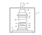
- FIG. 1 is a cross-sectional view showing a room temperature bonding apparatus main body.
- FIG. 2 is a cross-sectional view showing the bonding chamber.
- FIG. 3 is a cross-sectional view showing the heat chamber.
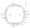
- FIG. 4 is a plan view showing the upper cartridge.
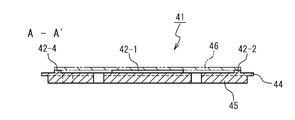
- FIG. 5 is a cross-sectional view showing the upper cartridge.
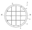
- FIG. 6 is a plan view showing the lower cartridge.
- FIG. 7 is a cross-sectional view showing the lower cartridge.
- FIG. 8 is a block diagram showing a room temperature bonding apparatus control apparatus.
- FIG. 9 is a flowchart showing a room temperature bonding method according to the present invention.
- FIG. 10 is a cross-sectional view showing another heat chamber.
- FIG. 11 is a cross-sectional view showing still another heat chamber.
- FIG. 12 is a cross-sectional view showing still another heat chamber.
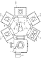
- FIG. 13 is a cross-sectional view showing another room temperature bonding apparatus main body.
- the room temperature bonding apparatus includes a room temperature bonding apparatus main body and a room temperature bonding apparatus controller.
- the room-temperature bonding apparatus main body includes a load lock chamber 1, a bonding chamber 2, and a heat chamber 3.
- the load lock chamber 1, the joining chamber 2, and the heat chamber 3 are containers that seal the inside from the environment.
- the room temperature bonding apparatus main body further includes a gate valve 5 and a gate valve 6.
- the gate valve 5 is interposed between the load lock chamber 1 and the bonding chamber 2, and forms a first gate that connects the inside of the bonding chamber 2 and the inside of the load lock chamber 1.
- the gate valve 5 is controlled by the bonding device control device to close the first gate or open the first gate.
- the gate valve 6 is interposed between the load lock chamber 1 and the heat chamber 3, and forms a second gate that connects the inside of the heat chamber 3 and the inside of the load lock chamber 1.
- the gate valve 6 is controlled by the bonding device control device to close the second gate or open the second gate.
- the load lock chamber 1 has a lid (not shown).
- the lid closes the gate connecting the environment and the interior of the load lock chamber 1 or opens the gate.
- the load lock chamber 1 includes a vacuum pump (not shown).
- the vacuum pump exhausts gas from the inside of the load lock chamber 1 by being controlled by the joining device controller.
- the vacuum pump include a turbo molecular pump, a cryopump, and an oil diffusion pump.
- the load lock chamber 1 further includes a plurality of shelves 7 and a transfer robot 8 inside.
- a plurality of cartridges are placed on the plurality of shelves 7.
- the transfer robot 8 is controlled by the bonding device control device to transfer the cartridges arranged on the plurality of shelves 7 to the bonding chamber 2 or the bonding chamber 2. Are transported to the plurality of shelves 7.
- the transfer robot 8 is controlled by the bonding apparatus control device to transfer the cartridges arranged on the plurality of shelves 7 to the heat chamber 3 or heat
- the cartridge arranged in the chamber 3 is conveyed to a plurality of shelves 7.
- the bonding chamber 2 includes a vacuum pump 10.
- the vacuum pump 10 evacuates gas from the inside of the bonding chamber 2 by being controlled by the bonding apparatus control device when the gate valve 5 is closed.
- Examples of the vacuum pump 10 include a turbo molecular pump, a cryopump, and an oil diffusion pump.
- the heat chamber 3 includes a vacuum pump (not shown).
- the vacuum pump exhausts gas from the inside of the heat chamber 3 by being controlled by the joining device control device when the gate valve 6 is closed.
- Examples of the vacuum pump include a turbo molecular pump, a cryopump, and an oil diffusion pump.
- the bonding chamber 2 further includes a positioning stage carriage 11 and an alignment mechanism 12, as shown in FIG.
- the positioning stage carriage 11 is formed in a plate shape.
- the positioning stage carriage 11 is disposed inside the bonding chamber 2 and is supported so as to be able to move in parallel in the horizontal direction and to be rotatable around a rotation axis that is parallel to the vertical direction.
- the positioning stage carriage 11 is used for holding a cartridge.
- the alignment mechanism 12 is controlled by the bonding apparatus control device so that the positioning stage carriage 11 moves in parallel in the horizontal direction, or centering on a rotation axis in which the positioning stage carriage 11 is parallel to the vertical direction.
- the positioning stage carriage 11 is moved so as to rotate.
- the bonding chamber 2 further includes a pressure contact shaft 14, an electrostatic chuck 15, a pressure contact mechanism 16, and a load meter 17.
- the pressure contact shaft 14 is supported so as to be movable in the vertical direction with respect to the bonding chamber 2.
- the electrostatic chuck 15 is disposed at the lower end of the press contact shaft 14.
- the electrostatic chuck 15 is formed of a dielectric layer in which internal electrodes are disposed.
- the dielectric layer is made of alumina ceramic and has a flat surface at the lower end.
- the electrostatic chuck 15 is controlled by the bonding device control device so that a predetermined applied voltage is applied to the internal electrode.
- the electrostatic chuck 15 holds a wafer disposed near the flat surface of the dielectric layer with an electrostatic force when a predetermined applied voltage is applied to the internal electrode.
- the pressure contact mechanism 16 is moved by the bonding apparatus control device to translate the pressure contact shaft 14 in the vertical direction with respect to the bonding chamber 2.
- the pressure contact mechanism 16 further measures the position where the electrostatic chuck 15 is disposed, and outputs the position to the bonding apparatus control device.
- the load meter 17 measures the load applied to the pressure contact shaft 14, thereby measuring the load applied to the wafer held by the electrostatic chuck 15, and outputs the load to the bonding apparatus controller.
- the bonding chamber 2 further includes an ion gun 18 and an electron source 19.
- the ion gun 18 emits accelerated argon ions by being controlled by the bonding device controller.
- the ion gun 18 discharges the argon ions into the space between the positioning stage carriage 11 and the electrostatic chuck 15, that is, a wafer held by the positioning stage carriage 11 and a wafer held by the electrostatic chuck 15. Is fixed to the bonding chamber 2 so that the argon ions are irradiated.
- the electron source 19 emits accelerated electrons by being controlled by the bonding apparatus controller.
- the electron source 19 is configured so that electrons are emitted into the space between the alignment mechanism 12 and the electrostatic chuck 15, that is, a wafer held on the positioning stage carriage 11 and a wafer held on the electrostatic chuck 15. Are fixed to the bonding chamber 2 so that the electrons are irradiated.
- the ion gun 18 further includes a metal target (not shown).
- the metal target is formed of a plurality of metals and is disposed at a position where the argon ions are irradiated.
- the metal target releases the plurality of metal atoms to the atmosphere inside the bonding chamber 2 when the argon ions are irradiated.
- the metal target can be replaced with a metal grid.
- the metal grid is a metal member having an opening, and is disposed at the exit end of the ion gun 18.
- the metal grid emits the plurality of metal atoms to the atmosphere inside the bonding chamber 2 by irradiating the argon ions in the same manner as the metal target.
- the metal target can be omitted when it is not necessary to attach metal atoms to the bonding surface of the wafer.
- FIG. 3 shows the heat chamber 3.
- the heat chamber 3 includes a chamber base 21, a heat sink 22, a heat insulating member 23, a sample table 24, and a heater 25.
- the chamber base 21 forms a part of the heat chamber 3 and is a foundation that supports the heat sink 22, the heat insulating member 23, the sample stage 24, and the heater 25.
- the heat sink 22 is fixed to the chamber base 21.
- the heat insulating member 23 is made of quartz and is fixed to the chamber base 21 via the heat sink 22.
- the heat insulating member 23 can also be formed of another heat insulating material having a high thermal shock property different from quartz. An example of the heat insulating material is quartz glass.
- the heat insulating member 23 includes a flow path 26. The flow path 26 forms a conduit through which gaseous nitrogen flows.
- the gaseous nitrogen is supplied from the outside of the heat chamber 3 by a cooling device (not shown).
- the sample stage 24 is made of aluminum nitride AlN, and is fixed to the chamber base 21 via a heat insulating member 23. Note that the sample stage 24 can also be formed of another material having an excellent thermal conductivity different from that of aluminum nitride AlN. As the material, silicon carbide SiC is exemplified.
- the sample table 24 has a holding surface 27 on the side opposite to the side joined to the heat insulating member 23. The holding surface 27 is formed so that the cartridge is held on the sample stage 24.
- the heater 25 is disposed inside the sample table 24. The heater 25 generates heat by being controlled by the room temperature bonding apparatus controller, and heats the wafer placed on the cartridge. At this time, the heat sink 22 prevents the heat chamber 3 from being heated when the cooled refrigerant is constantly supplied from the outside of the heat chamber 3 and the heater 25 generates heat.
- the heat chamber 3 further includes a substrate holder 31, a heat sink 32, an angle adjusting mechanism 33, a load cell 34, and a pressurizing mechanism 35.
- the substrate holder 31 is made of quartz.
- the substrate holder 31 has a holding surface 36 on the side facing the sample table 24.
- the pressing surface 36 is formed flat.
- the substrate pressing member 31 is bonded to the heat sink 32 on the side opposite to the side on which the pressing surface 36 is formed.
- the heat sink 32 is bonded to the angle adjustment mechanism 33 on the side opposite to the side bonded to the substrate holder 31.
- the angle adjustment mechanism 33 is joined to the load cell 34.
- the load cell 34 is supported so that it can move in a direction perpendicular to the upper surface of the chamber base 21. At this time, the heat sink 32 prevents the angle adjusting mechanism 33 and the load cell 34 from being heated when the cooled refrigerant is constantly supplied from the outside of the heat chamber 3 and the substrate holder 31 is heated.
- the pressurizing mechanism 35 is controlled by the room temperature bonding apparatus control device to move the angle adjusting mechanism 33 in the vertical direction with respect to the upper surface of the chamber base 21, that is, press the substrate against the upper surface of the chamber base 21. 31 is moved in the vertical direction.
- the load cell 34 includes a piezoelectric element, measures the load applied to the pressing surface 36, and measures the bias of the load applied to the substrate pressing 31.
- the load cell 34 outputs the load and the bias to the room temperature bonding apparatus controller.
- the angle adjustment mechanism 33 changes the direction in which the pressing surface 36 faces by being controlled by the room temperature bonding apparatus controller.
- the load cell 34 may have a large error in measurement values when the piezoelectric element is heated. Since the load cell 34 is prevented from being heated by the heat sink 32, the load and the deviation can be measured with higher accuracy.
- the plurality of cartridges placed on the plurality of shelves 7 include an upper cartridge and a lower cartridge.
- FIG. 4 shows the cartridge thereon.
- the upper cartridge 41 is made of aluminum, stainless steel, or aluminum nitride, and has a generally disc shape.
- the upper cartridge 41 has a plurality of island portions 42-1 to 42-4 formed on the upper surface of the disk.
- the plurality of island portions 42-1 to 42-4 are formed as protrusions protruding from the upper surface of the disk, and the upper ends thereof are formed along one plane.
- the upper cartridge 41 is formed with a flange portion 44 and a main body portion 45.
- the main body portion 45 is formed in a cylindrical shape.
- the flange portion 44 is formed so as to protrude from the side surface of the cylinder of the main body portion 45 and is formed in a disk shape. That is, the upper cartridge 41 is gripped by the transport robot 8 by being squeezed by the flange portion 44.
- the upper cartridge 41 is used by placing the upper wafer 46 on the plurality of island portions 42-1 to 42-4. That is, the plurality of island portions 42-1 to 42-4 are formed along the outer periphery of the upper wafer 46.
- the upper cartridge 41 is arranged so that the lower surface of the upper wafer 46 does not contact the upper cartridge 41 when the upper wafer 46 is placed on the plurality of island portions 42-1 to 42-4.
- the side surface is formed so as not to be contaminated by the upper cartridge 41.
- the upper cartridge 41 is further formed with a flow path through which the space between the upper cartridge 41 and the upper wafer 46 communicates with the outside when the upper wafer 46 is placed on the plurality of island portions 42-1 to 42-4.
- a plurality of island portions 42-1 to 42-4 are formed. That is, the plurality of island portions 42-1 to 42-4 are formed so as not to be connected to each other.
- FIG. 6 shows the lower cartridge 51.
- the lower cartridge 51 is made of aluminum, stainless steel, or aluminum nitride, is formed in a generally disc shape, and is used for placing a lower wafer.
- the lower cartridge 51 further has an island portion 52 formed on the upper surface of the disk.
- the island portion 52 is formed as a protrusion protruding from the upper surface of the disk, is formed in a shape substantially equal to the shape of the lower wafer placed on the lower cartridge 51, and is formed so that the upper end is along one plane.
- the island portion 52 has a groove 53 formed at the upper end.
- the grooves 53 are formed in a lattice shape at the upper end.
- the groove 53 is further formed so as to be connected to the side surface of the island portion 52.
- the lower cartridge 51 is formed with a flange portion 54 and a main body portion 55.
- the main body portion 55 is formed in a cylindrical shape.
- the flange portion 54 is formed so as to protrude from the side surface of the cylinder of the main body portion 55 and is formed in a disk shape. That is, the lower cartridge 51 is gripped by the transfer robot 8 by the flange portion 54 being rubbed.
- the lower cartridge 51 is used with the lower wafer 56 placed on the island portion 52. That is, the island portion 52 is formed along the outer periphery of the lower wafer 56.
- the lower cartridge 51 further has an island portion 52 so that when the lower wafer 56 is placed on the island portion 52, a flow path is formed so that a space between the lower cartridge 51 and the lower wafer 56 communicates with the outside. Is formed. That is, the island portions 52 are formed so as not to be connected to each other.
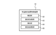
- FIG. 8 shows the room temperature bonding apparatus controller 61.
- the room temperature bonding apparatus control device 61 is a computer and includes a CPU, a storage device, a removable memory drive, a communication device, an input device, an output device, and an interface (not shown).
- the CPU executes a computer program installed in the room temperature bonding apparatus control device 61 to control the storage device, the removable memory drive, the communication device, the input device, the output device, and the interface.
- the storage device records the computer program.
- the storage device further records information used by the CPU.
- the removable memory drive is used when the computer program is installed in the room temperature bonding apparatus controller 61 when a recording medium in which the computer program is recorded is inserted.
- the communication apparatus downloads a computer program from another computer connected to the room temperature bonding apparatus controller 61 to the room temperature bonding apparatus controller 61 via a communication network, and installs the computer program in the room temperature bonding apparatus controller 61.
- the input device outputs information generated by being operated by the user to the CPU. Examples of the input device include a keyboard and a mouse.
- the output device outputs the information generated by the CPU so that it can be recognized by the user. Examples of the output device include a display that displays an image generated by the CPU.
- the interface outputs information generated by an external device connected to the room temperature bonding apparatus control device 61 to the CPU, and outputs information generated by the CPU to the external device.
- the external devices include a gate valve 5, a gate valve 6, a transfer robot 8, a vacuum pump exhausted from the load lock chamber 1, a vacuum pump exhausted from the heat chamber 3, a vacuum pump 10, an alignment mechanism 12, and an electrostatic chuck 15.
- a pressure contact mechanism 16, a load meter 17, an ion gun 18, an electron source 19, a heater 25, a cooling device that supplies a refrigerant to the flow path 26, a heater 25, an angle adjustment mechanism 33, a load cell 34, and a pressurization mechanism 35 are included.
- the computer program installed in the room temperature bonding apparatus controller 61 is formed of a plurality of computer programs for causing the room temperature bonding apparatus controller 61 to realize a plurality of functions.
- the plurality of functions include a conveyance unit 62, a pre-bonding heating unit 63, a bonding unit 64, and a post-bonding heating unit 65.
- the transfer unit 62 is configured so that when the gate valve 5 and the gate valve 6 are closed, a preliminary atmosphere having a predetermined degree of vacuum is generated inside the load lock chamber 1 or the load lock chamber 1.
- the vacuum pump of the load lock chamber 1 is controlled so that an atmospheric pressure atmosphere is generated inside.
- the transfer unit 62 controls the gate valve 5 so that the gate valve 5 opens and closes when the preliminary atmosphere is generated inside the load lock chamber 1, and the gate valve 6 opens and closes so that the gate valve 6 opens and closes. Control.
- the transport unit 62 is configured so that when the gate valve 5 is opened, the upper cartridge 41 or the lower cartridge 51 arranged on the plurality of shelves 7 is transported to the positioning stage carriage 11 of the joining chamber 2, or The transfer robot 8 is controlled so that the upper cartridge 41 or the lower cartridge 51 held by the positioning stage carriage 11 is transferred to the plurality of shelves 7 of the load lock chamber 1.
- the transport unit 62 is configured so that when the gate valve 6 is opened, the upper cartridge 41 or the lower cartridge 51 arranged on the plurality of shelves 7 is transported to the sample stage 24 of the heat chamber 3 or heat
- the transfer robot 8 is controlled so that the upper cartridge 41 or the lower cartridge 51 held on the sample stage 24 of the chamber 3 is transferred to the plurality of shelves 7 of the load lock chamber 1.
- the pre-bonding heating unit 63 controls the vacuum pump of the heat chamber 3 so that a desorption atmosphere having a predetermined degree of vacuum is generated inside the heat chamber 3 when the gate valve 6 is closed.
- the pre-bonding heating unit 63 is placed on the upper cartridge 41 when the desorption atmosphere is generated inside the heat chamber 3 and the upper cartridge 41 is held on the sample stage 24 of the heat chamber 3.
- the heater 25 is controlled so that the upper wafer 46 is heated at a predetermined desorption temperature, that is, the adsorbed substance is desorbed from the upper wafer 46.
- the adsorbed substance is a substance adsorbed on the upper wafer 46, and examples thereof include water and atmospheric components.
- An example of the desorption temperature is 200 ° C.
- the pre-bonding heating unit 63 controls the heater 25 so that the upper wafer 46 is not heated after the upper wafer 46 is heated for a predetermined time, that is, after the adsorbed substance is sufficiently desorbed from the upper wafer 46. Then, the cooling device of the heat chamber 3 is controlled so that gaseous nitrogen flows through the flow path 26, that is, the upper wafer 46 is cooled to the bonding temperature.
- the bonding temperature is set so as to be included in a temperature range in which a product manufactured from the upper wafer 46 is used.
- the pre-bonding heating unit 63 is placed on the lower cartridge 51 when the desorption atmosphere is generated inside the heat chamber 3 and the lower cartridge 51 is held on the sample stage 24 of the heat chamber 3.
- the heater 25 is controlled so that the lower wafer 56 is heated at a predetermined desorption temperature, that is, the adsorbed substance is desorbed from the lower wafer 56.
- the pre-bonding heating unit 63 controls the heater 25 so that the lower wafer 56 is not heated after the lower wafer 56 is heated for a predetermined time, that is, after the adsorbed substance is sufficiently desorbed from the lower wafer 56.
- the cooling device of the heat chamber 3 is controlled so that gaseous nitrogen flows through the flow path 26, that is, the lower wafer 56 is cooled to the bonding temperature.
- the joint 64 controls the pressure contact mechanism 16 so that the electrostatic chuck 15 is lowered when the upper cartridge 41 is placed on the positioning stage carriage 11.
- the joint portion 64 controls the load meter 17 so that the load applied to the electrostatic chuck 15 is measured when the electrostatic chuck 15 is lowered.
- the joint portion 64 calculates the timing at which the load reaches a predetermined contact load, that is, calculates the timing at which the upper wafer 46 placed on the upper cartridge 41 contacts the electrostatic chuck 15 based on the load.
- the joining part 64 controls the press contact mechanism 16 so that the electrostatic chuck 15 stops at the timing.
- the bonding portion 64 controls the electrostatic chuck 15 so that the electrostatic chuck 15 holds the upper wafer 46 when the electrostatic chuck 15 is in contact with the upper wafer 46 placed on the upper cartridge 41.
- the joining portion 64 controls the pressure contact mechanism 16 so that the electrostatic chuck 15 is raised when the upper chuck 46 held on the upper cartridge 41 is held by the electrostatic chuck 15.
- the junction 64 controls the vacuum pump 10 so that a junction atmosphere having a predetermined degree of vacuum is generated inside the junction chamber 2 when the gate valve 5 is closed.
- the bonding unit 64 further controls the ion gun 18 so that the upper wafer 46 and the lower wafer 56 are irradiated with argon ions when the bonding atmosphere is generated inside the bonding chamber 2.
- the junction 64 further controls the electron source 19 so that electrons are emitted while the argon ions are being emitted.
- the bonding portion 64 and the lower wafer 56 placed on the lower cartridge 51 and the upper portion are connected.
- the pressure contact mechanism 16 is controlled so that the wafer 46 approaches a predetermined alignment distance.
- the bonding portion 64 is further positioned so that when the upper wafer 46 and the lower wafer 56 are separated by the alignment distance, the lower wafer 56 is arranged at a predetermined alignment position with respect to the upper wafer 46.
- the alignment mechanism 12 is controlled. The alignment position is set so that when the electrostatic chuck 15 is lowered, the upper wafer 46 and the lower wafer 56 are bonded as designed.
- the bonding portion 64 further controls the pressure contact mechanism 16 so that the electrostatic chuck 15 is lowered when the lower wafer 56 is disposed at the alignment position.
- the joint portion 64 controls the load meter 17 so that the load applied to the electrostatic chuck 15 is measured when the electrostatic chuck 15 is lowered.
- the joining part 64 calculates the timing when the load reaches a predetermined joining load.
- the bonding portion 64 controls the pressure contact mechanism 16 so that the electrostatic chuck 15 stops at that timing, that is, the bonding load is applied to the upper wafer 46 and the lower wafer 56.
- the bonding unit 64 is configured so that the bonded wafer manufactured from the upper wafer 46 and the lower wafer 56 is detached from the electrostatic chuck 15 after the bonding load is applied to the upper wafer 46 and the lower wafer 56 for a predetermined bonding time. In addition, the electrostatic chuck 15 is controlled. The bonding unit 64 controls the pressure contact mechanism 16 so that the electrostatic chuck 15 is raised after the bonded wafer is detached from the electrostatic chuck 15.
- the post-joining heating unit 65 controls the pressurizing mechanism 35 so that the substrate presser 31 is lowered when the lower cartridge 51 is held on the sample stage 24 of the heat chamber 3.
- the post-bonding heating unit 65 measures the load applied to the substrate retainer 31 when the substrate retainer 31 is lowered, and measures the bias of the load applied to the substrate retainer 31.
- the load cell 34 is controlled.
- the post-bonding heating unit 65 controls the pressurizing mechanism 35 so that a predetermined pressing load is applied to the bonded wafer.
- the post-bonding heating unit 65 is configured so that the pressing surface 36 of the substrate holder 31 is parallel to the upper surface of the bonded wafer based on the deviation, that is, the pressing load is uniformly applied to the bonding wear.
- the angle adjustment mechanism 33 is controlled.
- the post-bonding heating unit 65 is configured so that the bonded wafer is heated at a predetermined annealing temperature when a predetermined pressing load is applied to the bonded wafer, that is, the bonded wafer is annealed.
- the heater 25 is controlled.
- An example of the annealing temperature is 480 ° C.
- the post-bonding heating unit 65 controls the heater 25 so that the lower cartridge 51 is not heated after the bonded wafer is heated for a predetermined time, that is, after the bonded wafer is annealed.
- the cooling device of the heat chamber 3 is controlled so that nitrogen flows, that is, the lower cartridge 51 is cooled to the portable temperature.
- the post-bonding heating unit 65 controls the pressurizing mechanism 35 so that the substrate presser 31 is further raised after the bonded wafer is annealed.
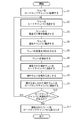
- FIG. 9 shows an embodiment of the room temperature bonding method according to the present invention.
- the room temperature bonding method is performed using the room temperature bonding apparatus according to the present invention.
- the room temperature bonding apparatus controller 61 controls the gate valve 5 so that the first gate connecting the inside of the load lock chamber 1 and the inside of the bonding chamber 2 is closed,
- the gate valve 6 is controlled so that the second gate connecting the inside of the heat chamber 3 is closed.
- the room temperature bonding apparatus controller 61 controls the vacuum pump of the load lock chamber 1 so that an atmospheric pressure atmosphere is generated inside the load lock chamber 1 when the gate valve 5 and the gate valve 6 are closed.
- the vacuum pump 10 is controlled so that a bonding atmosphere is generated inside the bonding chamber 2, and the vacuum pump of the heat chamber 3 is controlled so that a desorption atmosphere is generated inside the heat chamber 3.
- the user opens the lid of the load lock chamber 1 and arranges a plurality of cartridges on the plurality of shelves 7 when an atmospheric pressure atmosphere is generated inside the load lock chamber 1.
- the plurality of cartridges include a plurality of upper cartridges 41 and a plurality of lower cartridges 51.
- An upper wafer 46 is placed on the upper cartridge 41.
- a lower wafer 56 is placed on the lower cartridge 51.
- the user closes the lid of the load lock chamber 1 after arranging the cartridges on the shelves 7.
- the room temperature bonding apparatus controller 61 controls the vacuum pump of the load lock chamber 1 so that a preliminary atmosphere is generated inside the load lock chamber 1 when the lid of the load lock chamber 1 is closed (step S1). ).
- the room temperature bonding apparatus controller 61 controls the gate valve 6 so that the gate valve 6 is opened when a preliminary atmosphere is generated inside the load lock chamber 1.
- the room temperature bonding apparatus controller 61 transfers one upper cartridge 41 of the plurality of cartridges arranged on the plurality of shelves 7 to the sample stage 24 of the heat chamber 3. In this manner, the transfer robot 8 is controlled (step S2).
- the room temperature bonding apparatus controller 61 controls the gate valve 6 so that the gate valve 6 is closed after the upper cartridge 41 is held on the sample stage 24 of the heat chamber 3.
- the room temperature bonding apparatus controller 61 controls the vacuum pump of the heat chamber 3 so that a desorption atmosphere is generated inside the heat chamber 3 when the gate valve 6 is closed.
- the room temperature bonding apparatus controller 61 is configured so that the upper wafer 46 placed on the upper cartridge 41 is heated at a predetermined desorption temperature when the desorption atmosphere is generated inside the heat chamber 3. That is, the heater 25 is controlled so that the adsorbed material is desorbed from the upper wafer 46 (step S3).
- the room temperature bonding apparatus controller 61 controls the heater 25 so that the upper wafer 46 is not heated after the upper wafer 46 is heated for a predetermined time, that is, after the adsorbed substance is sufficiently desorbed from the upper wafer 46.
- the cooling device of the heat chamber 3 is controlled so that gaseous nitrogen flows through the flow path 26, that is, the upper wafer 46 is cooled to the bonding temperature.
- the room temperature bonding apparatus controller 61 controls the gate valve 6 so that the gate valve 6 is opened after the adsorbed substance is sufficiently desorbed from the upper wafer 46.
- the room temperature bonding apparatus controller 61 controls the transfer robot 8 so that the upper cartridge 41 is transferred from the sample stage 24 of the heat chamber 3 to the plurality of shelves 7 after the upper wafer 46 is cooled to the bonding temperature.
- step S2 The room temperature bonding apparatus controller 61 controls the gate valve 6 so that the gate valve 6 is closed after the lower cartridge 51 is held on the sample stage 24 of the heat chamber 3.
- the room temperature bonding apparatus controller 61 controls the vacuum pump of the heat chamber 3 so that a desorption atmosphere is generated inside the heat chamber 3 when the gate valve 6 is closed.
- the room temperature bonding apparatus control device 61 is configured so that the lower wafer 56 placed on the lower cartridge 51 is heated at a predetermined desorption temperature when the desorption atmosphere is generated inside the heat chamber 3. That is, the heater 25 is controlled so that the adsorbed material is desorbed from the lower wafer 56 (step S3).
- the room temperature bonding apparatus controller 61 controls the heater 25 so that the lower wafer 56 is not heated after the lower wafer 56 is heated for a predetermined time, that is, after the adsorbed substance is sufficiently desorbed from the lower wafer 56.
- the cooling device of the heat chamber 3 is controlled so that gaseous nitrogen flows through the flow path 26, that is, the lower wafer 56 is cooled to the bonding temperature.
- the room temperature bonding apparatus controller 61 controls the gate valve 6 so that the gate valve 6 is opened after the adsorbed substance is sufficiently desorbed from the lower wafer 56.
- the room temperature bonding apparatus controller 61 controls the transfer robot 8 so that the lower cartridge 51 is transferred from the sample stage 24 of the heat chamber 3 to the plurality of shelves 7 after the lower wafer 56 is cooled to the bonding temperature.
- the room temperature bonding apparatus controller 61 controls the gate valve 5 so that the gate valve 5 is opened after the adsorbed substances are sufficiently desorbed from the upper wafer 46 and the lower wafer 56.
- the room temperature bonding apparatus controller 61 controls the transfer robot 8 so that the upper cartridge 41 on which the detached upper wafer 46 is placed is transferred from the plurality of shelves 7 to the positioning stage carriage 11 of the bonding chamber 2. .
- the room temperature bonding apparatus controller 61 controls the pressure contact mechanism 16 so that the electrostatic chuck 15 is lowered.
- the room temperature bonding apparatus controller 61 controls the load meter 17 so that the load applied to the electrostatic chuck 15 is measured when the electrostatic chuck 15 is lowered.
- the room temperature bonding apparatus controller 61 calculates the timing at which the load reaches a predetermined contact load, that is, the timing at which the upper wafer 46 placed on the upper cartridge 41 contacts the electrostatic chuck 15 based on the load. calculate.
- the room temperature bonding apparatus controller 61 controls the pressure contact mechanism 16 so that the electrostatic chuck 15 stops at that timing.
- the room temperature bonding apparatus controller 61 controls the electrostatic chuck 15 so that the electrostatic chuck 15 holds the upper wafer 46 when the electrostatic chuck 15 is in contact with the upper wafer 46 mounted on the upper cartridge 41. Control.
- the room-temperature bonding apparatus controller 61 controls the pressure contact mechanism 16 so that the electrostatic chuck 15 is raised when the upper chuck 46 held on the upper cartridge 41 is held by the electrostatic chuck 15.
- the room-temperature bonding apparatus control device 61 is configured so that the upper cartridge 41 on which the upper wafer 46 is not placed is transported from the positioning stage carriage 11 to the plurality of shelves 7 after the electrostatic chuck 15 has moved up to a predetermined activation position.
- the transfer robot 8 is controlled.
- the room temperature bonding apparatus controller 61 controls the gate valve 5 so that the gate valve 5 is closed after the lower cartridge 51 is held by the positioning stage carriage 11 (step S4).
- the room temperature bonding apparatus controller 61 controls the vacuum pump 10 so that a bonding atmosphere is generated inside the bonding chamber 2 when the gate valve 5 is closed.
- the room temperature bonding apparatus controller 61 further controls the ion gun 18 so that the upper wafer 46 and the lower wafer 56 are irradiated with argon ions when the bonding atmosphere is generated inside the bonding chamber 2.
- the room-temperature bonding apparatus controller 61 further controls the electron source 19 so that electrons are emitted while the argon ions are being emitted (step S5).
- the room temperature bonding apparatus controller 61 controls the pressure contact mechanism 16 so that the lower wafer 56 and the upper wafer 46 are close to a predetermined alignment distance.
- the room temperature bonding apparatus controller 61 further arranges the lower wafer 56 at a predetermined alignment position with respect to the upper wafer 46 when the upper wafer 46 and the lower wafer 56 are separated by the alignment distance.
- the alignment mechanism 12 is controlled.
- the room temperature bonding apparatus controller 61 further controls the pressure contact mechanism 16 so that the electrostatic chuck 15 is lowered after the lower wafer 56 is disposed at the alignment position.
- the room temperature bonding apparatus controller 61 controls the load meter 17 so that the load applied to the electrostatic chuck 15 is measured when the electrostatic chuck 15 is lowered.
- the room temperature bonding apparatus controller 61 calculates the timing at which the load reaches a predetermined bonding load.
- the room temperature bonding apparatus control device 61 controls the pressure welding mechanism 16 so that the electrostatic chuck 15 stops at that timing, that is, the bonding load is applied to the upper wafer 46 and the lower wafer 56 (step). S6).
- the lower wafer 56 and the upper wafer 46 are bonded to each other when a bonding load is applied to form a single bonded wafer.
- the room temperature bonding apparatus controller 61 controls the electrostatic chuck 15 so that the bonded wafer is detached from the electrostatic chuck 15 after the bonding load is applied to the bonded wafer for a predetermined bonding time.
- the room-temperature bonding apparatus controller 61 controls the pressure contact mechanism 16 so that the electrostatic chuck 15 is raised after the bonded wafer is detached from the electrostatic chuck 15.
- the room temperature bonding apparatus controller 61 controls the gate valve 5 so that the gate valve 5 is opened after the electrostatic chuck 15 is sufficiently raised.
- the room temperature bonding apparatus controller 61 transfers the transfer robot 8 so that the lower cartridge 51 on which the bonded wafer is placed is transferred from the positioning stage carriage 11 to the load lock chamber 1 when the gate valve 5 is opened. To control.
- the room temperature bonding apparatus controller 61 controls the gate valve 6 so that the gate valve 6 is opened when a preliminary atmosphere is generated inside the load lock chamber 1.
- the room temperature bonding apparatus controller 61 is configured so that when the gate valve 6 is opened, the lower cartridge 51 on which the bonded wafer is placed is transported from the load lock chamber 1 to the sample stage 24 of the heat chamber 3.
- the transfer robot 8 is controlled (step S7).
- the room temperature bonding apparatus controller 61 controls the pressurizing mechanism 35 so that the substrate presser 31 is lowered when the lower cartridge 51 is held on the sample stage 24 of the heat chamber 3.
- the room temperature bonding apparatus control device 61 measures the bias applied to the substrate holder 31 so that the load applied to the substrate holder 31 is measured when the substrate holder 31 is lowered.
- the load cell 34 is controlled.
- the room temperature bonding apparatus controller 61 controls the pressurizing mechanism 35 at a predetermined sampling period so that a predetermined pressing load is applied to the bonded wafer. Based on the deviation, the room-temperature bonding apparatus control device 61 applies the pressing load uniformly to the bonding wear so that the pressing surface 36 of the substrate pressing member 31 is parallel to the upper surface of the bonding wafer.
- the angle adjustment mechanism 33 is controlled at a predetermined sampling period.
- the room temperature bonding apparatus controller 61 is configured so that the bonded wafer is heated at a predetermined annealing temperature when the holding load is applied to the bonded wafer, that is, the bonded wafer is annealed.
- the heater 25 is controlled at a predetermined sampling period (step S8).
- the bonded wafer is annealed by heating for a predetermined annealing time, and the residual stress is reduced.
- An example of the annealing time is several minutes.
- the room temperature bonding apparatus control device 61 controls the heater 25 so that the lower cartridge 51 is not heated after the bonded wafer is annealed, so that gaseous nitrogen flows in the flow path 26, that is, the lower cartridge 51 is enabled.
- the cooling device of the heat chamber 3 is controlled so as to be cooled to the carrying temperature. Room temperature is illustrated as the portable temperature.
- the room temperature bonding apparatus controller 61 controls the pressurizing mechanism 35 so that the substrate presser 31 is further raised after the bonded wafer is annealed.
- the room temperature bonding apparatus controller 61 transfers the substrate cartridge 31 so that the lower cartridge 51 on which the annealed bonded wafer is placed is transferred from the positioning stage carriage 11 to the plurality of shelves 7 after the substrate presser 31 is sufficiently raised.
- the robot 8 is controlled (step S9).
- the room temperature bonding apparatus control device 61 is arranged when the upper cartridge 41 on which the upper wafer 46 is placed and the lower cartridge 51 on which the lower wafer 56 is placed are arranged on the plurality of shelves 7 (YES in step S10). The operations from step S2 to step S9 are repeated again.
- the room temperature bonding apparatus controller 61 controls the gate valve 5 so that the gate valve 5 is closed when a wafer to be bonded is not arranged on the plurality of shelves 7 (NO in step S10).
- the gate valve 6 is controlled so that the gate valve 6 is closed.
- the room temperature bonding apparatus controller 61 controls the vacuum pump of the load lock chamber 1 so that an atmospheric pressure atmosphere is generated inside the load lock chamber 1 after the gate valve 5 and the gate valve 6 are closed.
- the user opens the lid of the load lock chamber 1 and takes out a plurality of cartridges from the plurality of shelves 7.
- the plurality of cartridges includes a plurality of upper cartridges 41 and a plurality of lower cartridges 51. The bonded wafer is placed on the lower cartridge 51.
- the upper cartridge 41 on which the upper wafer 46 is placed and the lower cartridge 51 on which the lower wafer 56 is placed are arranged on the plurality of shelves 7. Then, the room temperature bonding method is performed again.
- the contact area of the bonding surface bonded at room temperature becomes small, and sufficient bonding strength may not be obtained.
- the upper wafer 46 and the lower wafer 56 are bonded with a sufficient bonding strength when the waviness is large and bonded while applying a sufficiently large load.
- the upper wafer 46 and the lower wafer 56 have large waviness, and residual stress may be generated when they are joined while a sufficiently large load is applied. Such residual stress may adversely affect a product manufactured from the upper wafer 46 and the lower wafer 56. Examples of the adverse effects include functional defects and malfunctions.
- voids generated from the adsorbing material may be generated on the bonding surface, and the bonding strength may be reduced.
- Such a room temperature bonding method can reduce the adsorbed material remaining on the bonded surface of the bonded wafer by the operation of desorbing the adsorbed material from the upper wafer 46 and the lower wafer 56 (steps S2 to S3). As a result, voids can be prevented from occurring on the joint surface, and the joint strength can be improved.
- the room temperature bonding method according to the present invention operates to desorb the adsorbed material from the upper wafer 46 and the lower wafer 56 when the adsorbed material adsorbed on the upper wafer 46 and the lower wafer 56 is sufficiently small. (Steps S2 to S3) can be omitted. Such a room temperature bonding method can also produce a product with good quality more stably in the same manner as the room temperature bonding method in the above-described embodiment.
- Products made from bonded wafers may be required to be formed in a predetermined shape. Even when the waviness of the bonded wafer before annealing is large, the bonded wafer can be formed more flat by being annealed while the pressing load is applied, and is applied to such a product. be able to.
- the room temperature bonding method according to the present invention is performed when annealing is performed when the bonded wafer before annealing is sufficiently flat, that is, when bonding can be performed so that the bonded wafer is sufficiently flat. It is possible to omit applying the pressing load to the. Such a room temperature bonding method can also produce a product with good quality more stably in the same manner as the room temperature bonding method in the above-described embodiment.
- the load applied to the bonded wafer may increase due to thermal expansion of the bonded wafer and the apparatus that handles the bonded wafer when the bonded wafer is annealed.
- the bonded wafer may crack when the applied load is sufficiently large.
- the room temperature bonding method of the present invention since the load applied to the bonded wafer is controlled by the holding load, the bonded wafer can be prevented from cracking, and a product with good quality can be more stably produced. Can be produced.
- the room temperature bonding method according to the present invention suppresses the load applied to the bonded wafer when the apparatus that handles the bonded wafer is elastically deformed and the load applied to the bonded wafer does not exceed a predetermined load. It is also possible to omit the operation of performing feedback control so that the load becomes a pressing load after the load is once controlled.
- the heat chamber 3 in the above-described embodiment is replaced with another heat chamber.
- the heat chamber 70 includes a chamber base 21, a heat sink 22, a heat insulating member 23, a sample stage 24, and a heater 25 in the same manner as the heat chamber 3 in the above-described embodiment. I have.
- the heat chamber 70 further includes an electrostatic chuck 71, a heat insulating member 72, a heat sink 73, an angle adjusting mechanism 74, a load cell 75, a pressurizing mechanism 76, and a heater 77.
- the electrostatic chuck 71 has a holding surface 78 on the side facing the sample stage 24. The holding surface 78 is formed flat.
- the electrostatic chuck 71 is joined to the heat insulating member 72 on the side opposite to the side on which the holding surface 78 is formed.
- the electrostatic chuck 71 is controlled by the room temperature bonding apparatus controller 61 to hold a wafer disposed near the holding surface 78 with an electrostatic force.
- the heat insulating member 72 is made of quartz and joined to the heat sink 73.
- the heat insulating member 72 includes a flow path 79.
- the flow path 79 forms a conduit through which gaseous nitrogen flows.
- the gaseous nitrogen is supplied from the outside of the heat chamber 70 by a cooling device (not shown).
- the heat sink 73 is bonded to the angle adjusting mechanism 74 on the opposite side to the side bonded to the electrostatic chuck 71.
- the angle adjustment mechanism 74 is joined to the load cell 75.
- the load cell 75 is supported so that it can move in a direction perpendicular to the upper surface of the chamber base 21. At this time, the heat sink 73 prevents the angle adjusting mechanism 74 and the load cell 75 from being heated when the cooled refrigerant is constantly supplied from the outside of the heat chamber 70 and the electrostatic chuck 71 is heated. .
- the pressurizing mechanism 76 is controlled by the room temperature bonding apparatus control device to move the angle adjusting mechanism 74 in the vertical direction with respect to the upper surface of the chamber base 21, that is, electrostatically with respect to the upper surface of the chamber base 21.
- the chuck 71 is moved in the vertical direction.
- the load cell 75 includes a piezoelectric element, measures the load applied to the holding surface 78, and measures the bias of the load applied to the electrostatic chuck 71.
- the load cell 75 outputs the load and the bias to the room temperature bonding apparatus controller.
- the angle adjustment mechanism 74 changes the direction in which the holding surface 78 faces by being controlled by the room temperature bonding apparatus controller.
- the load cell 75 may have a large error in measurement values when the piezoelectric element is heated. Since the load cell 75 is prevented from being heated by the heat sink 73, the load and the deviation can be measured with higher accuracy.
- the heater 77 is disposed inside the electrostatic chuck 71.
- the heater 77 generates heat and is heated by the room temperature bonding apparatus controller 61 to heat the wafer held by the electrostatic chuck 71.
- the heat sink 73 prevents the load cell 75 from being heated when the cooled refrigerant is constantly supplied from the outside of the heat chamber 70 and the heater 77 generates heat.
- the room temperature bonding apparatus control device 61 controls the gate valve 6 so that the gate valve 6 is opened when a preliminary atmosphere is generated inside the load lock chamber 1.
- the room temperature bonding apparatus controller 61 transfers one upper cartridge 41 of the plurality of cartridges arranged on the plurality of shelves 7 to the sample stage 24 of the heat chamber 70.
- the transfer robot 8 is controlled.
- the room temperature bonding apparatus controller 61 controls the pressurizing mechanism 76 so that the electrostatic chuck 71 is lowered after the upper cartridge 41 is held on the sample stage 24 of the heat chamber 70.
- the room temperature bonding apparatus controller 61 controls the load cell 75 so that the load applied to the electrostatic chuck 71 is measured when the electrostatic chuck 71 is lowered.
- the room temperature bonding apparatus controller 61 calculates the timing at which the load reaches a predetermined contact load, that is, the timing at which the upper wafer 46 placed on the upper cartridge 41 contacts the electrostatic chuck 71 based on the load. calculate.
- the room temperature bonding apparatus controller 61 controls the pressurizing mechanism 76 so that the electrostatic chuck 71 stops at that timing.
- the room temperature bonding apparatus controller 61 controls the electrostatic chuck 71 so that the electrostatic chuck 71 holds the upper wafer 46 when the electrostatic chuck 71 is in contact with the upper wafer 46 mounted on the upper cartridge 41. Control.
- the room temperature bonding apparatus control device 61 controls the pressurizing mechanism 76 so that the electrostatic chuck 71 is raised when the upper chuck 46 held on the upper cartridge 41 is held by the electrostatic chuck 71.
- the room-temperature bonding apparatus control device 61 includes a transfer robot 8 so that the upper cartridge 41 on which the upper wafer 46 is not mounted is transferred from the sample stage 24 to the plurality of shelves 7 after the electrostatic chuck 71 has moved up to a predetermined position. To control.
- the room temperature bonding apparatus control device 61 includes a transfer robot so that the lower cartridge 51 on which the lower wafer 56 is placed is transferred from the plurality of shelves 7 to the sample stage 24 after the upper cartridge 41 is transferred to the plurality of shelves 7. 8 is controlled.
- the room temperature bonding apparatus controller 61 controls the gate valve 6 so that the gate valve 6 is closed after the lower cartridge 51 is held on the sample stage 24.
- the room temperature bonding apparatus controller 61 controls the vacuum pump of the heat chamber 70 so that a desorption atmosphere is generated inside the heat chamber 70 when the gate valve 6 is closed.
- the room temperature bonding apparatus controller 61 is configured so that the upper wafer 46 held by the electrostatic chuck 71 is heated at a predetermined desorption temperature when the desorption atmosphere is generated in the heat chamber 70.
- the heater 25 is controlled to control the heater 25 so that the lower wafer 56 placed on the lower cartridge 51 is heated at the desorption temperature.
- the room temperature bonding apparatus controller 61 controls the heater 77 so that the upper wafer 46 is not heated after the upper wafer 46 is heated for a predetermined time, so that gaseous nitrogen flows in the flow path 79, that is, the upper wafer.
- the cooling device of the heat chamber 70 is controlled so that 46 is cooled to the bonding temperature.
- the room temperature bonding apparatus controller 61 controls the heater 25 so that the lower wafer 56 is not heated after the lower wafer 56 is heated for a predetermined time, so that gaseous nitrogen flows in the flow path 26, that is, the lower wafer 56.
- the cooling device of the heat chamber 70 is controlled so that is cooled to the bonding temperature.
- the room temperature bonding apparatus controller 61 controls the gate valve 6 so that the gate valve 6 is opened after the adsorbed substances are sufficiently desorbed from the upper wafer 46 and the lower wafer 56.
- the room temperature bonding apparatus controller 61 controls the transfer robot 8 so that the lower cartridge 51 is transferred from the sample stage 24 of the heat chamber 70 to the plurality of shelves 7 after the lower wafer 56 is cooled to the bonding temperature.
- the room temperature bonding apparatus control device 61 includes a transfer robot so that after the lower cartridge 51 is transferred from the sample stage 24 of the heat chamber 70, the upper cartridge 41 on which no wafer is placed is transferred to the sample stage 24 of the heat chamber 70. 8 is controlled.
- the room temperature bonding apparatus controller 61 controls the pressurizing mechanism 76 so that the electrostatic chuck 71 is lowered after the upper cartridge 41 is held on the sample stage 24 of the heat chamber 70.
- the room temperature bonding apparatus controller 61 controls the load cell 75 so that the load applied to the electrostatic chuck 71 is measured when the electrostatic chuck 71 is lowered.
- the room temperature bonding apparatus controller 61 calculates the timing at which the load reaches a predetermined contact load, that is, the timing at which the upper wafer 46 held by the electrostatic chuck 71 contacts the upper cartridge 41 based on the load. To calculate.
- the room temperature bonding apparatus controller 61 controls the pressurizing mechanism 76 so that the electrostatic chuck 71 stops at that timing.
- the room temperature bonding apparatus controller 61 moves the electrostatic chuck 71 so that the upper wafer 46 is detached from the electrostatic chuck 71 when the electrostatic chuck 71 is in contact with the upper wafer 46 mounted on the upper cartridge 41. Control.
- the room temperature bonding apparatus controller 61 controls the pressurizing mechanism 76 so that the electrostatic chuck 71 moves up after the upper wafer 46 is detached from the electrostatic chuck 71.
- the room temperature bonding apparatus control device 61 includes a transfer robot 8 so that the upper cartridge 41 on which the upper wafer 46 is placed is transferred from the sample stage 24 to the plurality of shelves 7 after the electrostatic chuck 71 has moved up to a predetermined position. To control.
- the room temperature bonding method to which such an operation is applied can produce a product with good quality more stably in the same manner as the room temperature bonding method in the above-described embodiment.
- Such an operation can be executed in a shorter time than the operations in steps S2 to S3 in the above-described embodiment. For this reason, according to the room temperature bonding method to which such an operation is applied, a bonded wafer can be manufactured at a higher speed.
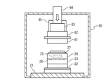
- FIG. 11 shows still another heat chamber.
- the heat chamber 80 includes a chamber base 21, a heat sink 22, a heat insulating member 23, a sample stage 24, and a heater 25 in the same manner as the heat chamber 3 in the above-described embodiment.
- the heat chamber 80 further includes a substrate pressing member 81, an angle adjusting mechanism 82, a load cell 83, a pressurizing mechanism 84, and a cooling mechanism 85.
- the substrate holder 81 is made of quartz.
- the substrate pressing member 81 has a pressing surface on the side facing the sample table 24. The pressing surface is formed flat.
- the substrate pressing member 81 is joined to the angle adjusting mechanism 82 on the side opposite to the side on which the pressing surface is formed.
- the angle adjustment mechanism 82 is joined to the load cell 83.
- the load cell 83 is supported so that it can move in a direction perpendicular to the upper surface of the chamber base 21.
- the pressure mechanism 84 is controlled by the room temperature bonding apparatus controller 61 to move the angle adjustment mechanism 82 in the vertical direction with respect to the upper surface of the chamber base 21, that is, press the substrate against the upper surface of the chamber base 21. 81 is moved in the vertical direction.
- the load cell 83 includes a piezoelectric element, measures the load applied to the pressing surface thereof, and measures the bias of the load applied to the substrate pressing member 81.
- the load cell 83 outputs the load and the bias to the room temperature bonding apparatus controller.
- the angle adjustment mechanism 82 is controlled by the room temperature bonding apparatus control device to change the direction in which the pressing surface is facing.
- the cooling mechanism 85 prevents the load cell 83 from being heated when the cooled refrigerant is constantly supplied from the outside of the heat chamber 80 and the substrate holder 81 is heated.
- the load cell 83 may have a large measurement value error due to heating of the piezoelectric element. Since the load cell 83 is prevented from being heated by the heat sink 32, the load and the deviation can be measured with higher accuracy.
- the room temperature bonding apparatus main body to which the heat chamber 80 is applied can be used in the same manner as the room temperature bonding apparatus main body to which the heat chamber 3 in the above-described embodiment is applied. For this reason, even when the room temperature bonding method according to the present invention is performed using the room temperature bonding apparatus main body to which the heat chamber 80 is applied, a product with good quality is obtained in the same manner as the room temperature bonding method in the above-described embodiment. It can be manufactured more stably. Furthermore, since the heat chamber 80 cools the load cell 83 from the vicinity as compared with the heat chamber 3 in the above-described embodiment, the load cell 83 can be cooled more reliably.
- the load cell 83 can measure the load and the bias with higher accuracy, and further improve the controllability for controlling the pressurizing mechanism 84 so that the pressing load is applied to the bonded wafer. Therefore, it is possible to further improve the controllability of controlling the angle adjusting mechanism 82 so that the pressing load is uniformly applied to the bonding wear.
- FIG. 12 shows still another heat chamber.
- the heat chamber 90 includes a chamber base 91, a heat insulating member 92, a sample table 93, and a heater 94.
- the chamber base 91 forms a part of the heat chamber 90 and is a foundation that supports the heat insulating member 92, the sample table 93, and the heater 94.
- the heat insulating member 92 is made of quartz and is fixed to the chamber base 91.
- the heat insulating member 92 includes a flow path 95.
- the channel 95 forms a conduit through which gaseous nitrogen flows. The gaseous nitrogen is supplied from the outside of the heat chamber 90 by a cooling device (not shown).
- the sample stage 93 is made of aluminum nitride AlN, and is fixed to the chamber base 91 via a heat insulating member 92.
- the sample table 93 has a holding surface 96 formed on the side opposite to the side joined to the heat insulating member 92.
- the holding surface 96 is formed so that the cartridge is held on the sample table 93.
- the heater 94 is disposed inside the sample table 93. The heater 94 generates heat by being controlled by the room temperature bonding apparatus controller 61 and heats the wafer placed on the cartridge.
- the heat chamber 90 further includes a substrate presser 101, an angle adjustment mechanism 102, a load cell 103, a pressurization mechanism 104, and a cooling mechanism 105.
- the substrate holder 101 is made of quartz.
- the substrate holder 101 has a holding surface on the side facing the sample table 93.
- the pressing surface is formed flat.
- the substrate presser 101 is joined to the angle adjustment mechanism 102 on the side opposite to the side where the pressing surface is formed.
- the angle adjustment mechanism 102 is joined to the load cell 103.
- the load cell 103 is supported so that it can move in a direction perpendicular to the upper surface of the chamber base 21.
- the pressure mechanism 104 is controlled by the room temperature bonding apparatus controller 61 to move the angle adjusting mechanism 102 in the vertical direction with respect to the upper surface of the chamber base 21, that is, press the substrate against the upper surface of the chamber base 21. 101 is moved in the vertical direction.
- the load cell 103 includes a piezoelectric element, measures the load applied to the pressing surface, and measures the bias of the load applied to the substrate pressing 101.
- the load cell 103 outputs the load and the bias to the room temperature bonding apparatus controller 61.
- the angle adjusting mechanism 102 is controlled by the room temperature bonding apparatus controller 61 to change the direction in which the pressing surface is facing.
- the cooling mechanism 105 is constantly supplied with the cooled refrigerant from the outside of the heat chamber 90, cools the heat chamber 90, and prevents the load cell 103 from being heated. Since the load cell 103 is prevented from being heated by the heat sink 32, the load and the deviation can be measured with higher accuracy.
- the room temperature bonding apparatus body to which the heat chamber 90 is applied can be used in the same manner as the room temperature bonding apparatus body to which the heat chamber 3 in the above-described embodiment is applied. For this reason, even when the room temperature bonding method according to the present invention is performed using a room temperature bonding apparatus body to which the heat chamber 90 is applied, a product with good quality can be obtained in the same manner as the room temperature bonding method in the above-described embodiment. It can be manufactured more stably. Further, the heat chamber 90 can be formed in a smaller size and the inside of the heat chamber 90 can be simply formed by the heat sink 22 and the heat sink 32 than the heat chamber 3 in the above-described embodiment. it can.
- the room temperature bonding apparatus main body in the above-described embodiment further includes another heat chamber 110.
- the heat chamber 110 is a container that seals the inside from the environment.
- the room temperature bonding apparatus main body further includes a gate valve 111.
- the gate valve 111 is interposed between the load lock chamber 1 and the heat chamber 110, and forms a gate that connects the inside of the heat chamber 110 and the inside of the load lock chamber 1.
- the gate valve 111 is controlled by the room temperature bonding apparatus controller 61 to close the gate or open the gate.
- the heat chamber 110 includes a chamber base 21, a heat sink 22, a heat insulating member 23, a sample table 24, and a heater 25 in the same manner as the heat chamber 3 in the above-described embodiment.
- An angle adjustment mechanism 33, a load cell 34, and a pressure mechanism 35 are provided.
- Still another embodiment of the room temperature bonding method according to the present invention is performed using the room temperature bonding apparatus main body to which the heat chamber 110 is added, and steps S2 to S3 in the above-described embodiment are replaced with other operations. ing.
- the room temperature bonding apparatus controller 61 controls the gate valve 6 so that the gate valve 6 is opened when a preliminary atmosphere is generated inside the load lock chamber 1.
- the room temperature bonding apparatus controller 61 transfers one upper cartridge 41 of the plurality of cartridges arranged on the plurality of shelves 7 to the sample stage 24 of the heat chamber 3.
- the transfer robot 8 is controlled.
- the room temperature bonding apparatus controller 61 controls the transfer robot 8 so that one lower cartridge 51 of the plurality of cartridges arranged on the plurality of shelves 7 is transferred to the sample stage 24 of the heat chamber 110. To do.
- the room temperature bonding apparatus controller 61 controls the gate valve 6 so that the gate valve 6 is closed after the upper cartridge 41 is held on the sample stage 24 of the heat chamber 3.
- the room temperature bonding apparatus controller 61 controls the vacuum pump of the heat chamber 3 so that a desorption atmosphere is generated inside the heat chamber 3 when the gate valve 6 is closed.
- the room temperature bonding apparatus controller 61 is configured so that the upper wafer 46 placed on the upper cartridge 41 is heated at a predetermined desorption temperature when the desorption atmosphere is generated inside the heat chamber 3. That is, the heater 25 is controlled so that the adsorbed material is desorbed from the upper wafer 46.
- the room temperature bonding apparatus controller 61 controls the heater 25 so that the upper wafer 46 is not heated after the upper wafer 46 is heated for a predetermined time, that is, after the adsorbed substance is sufficiently desorbed from the upper wafer 46.
- the cooling device of the heat chamber 3 is controlled so that gaseous nitrogen flows through the flow path 26, that is, the upper wafer 46 is cooled to the bonding temperature.
- the room temperature bonding apparatus controller 61 controls the gate valve 6 so that the gate valve 6 is opened after the adsorbed substance is sufficiently desorbed from the upper wafer 46.
- the room temperature bonding apparatus controller 61 controls the gate valve 111 so that the gate valve 111 is closed after the lower cartridge 51 is held on the sample stage 24 of the heat chamber 110.
- the room temperature bonding apparatus controller 61 controls the vacuum pump of the heat chamber 110 so that a desorption atmosphere is generated inside the heat chamber 110 when the gate valve 111 is closed.
- the room temperature bonding apparatus controller 61 is configured to heat the lower wafer 56 placed on the lower cartridge 51 at a predetermined desorption temperature when the desorption atmosphere is generated inside the heat chamber 110. That is, the heater 25 is controlled so that the adsorbed material is desorbed from the lower wafer 56.
- the room temperature bonding apparatus controller 61 controls the heater 25 so that the lower wafer 56 is not heated after the lower wafer 56 is heated for a predetermined time, that is, after the adsorbed substance is sufficiently desorbed from the lower wafer 56.
- the cooling device of the heat chamber 110 is controlled so that gaseous nitrogen flows through the flow path 26, that is, the lower wafer 56 is cooled to the bonding temperature.
- the room temperature bonding apparatus controller 61 controls the gate valve 111 so that the gate valve 111 is opened after the adsorbed substance is sufficiently desorbed from the lower wafer 56.
- the operation of desorbing the adsorbed material from the lower wafer 56 is executed in parallel with the operation of desorbing the adsorbed material from the upper wafer 46.
- the room temperature bonding apparatus controller 61 controls the transfer robot 8 so that the upper cartridge 41 is transferred from the sample stage 24 of the heat chamber 3 to the plurality of shelves 7 after the upper wafer 46 is cooled to the bonding temperature.
- the room temperature bonding apparatus controller 61 controls the transfer robot 8 so that the lower cartridge 51 is transferred from the sample stage 24 of the heat chamber 110 to the plurality of shelves 7 after the lower wafer 56 is cooled to the bonding temperature. To do.
- the room temperature bonding method to which such an operation is applied can produce a product with good quality more stably in the same manner as the room temperature bonding method in the above-described embodiment.
- Such an operation can be executed in a shorter time than the operations in steps S2 to S3 in the above-described embodiment. For this reason, according to the room temperature bonding method to which such an operation is applied, a bonded wafer can be manufactured at a higher speed.
- the heat chamber 110 can also be used for the operation of annealing the bonded wafer (steps S7 to S8).
- the heat chamber 110 is replaced with another heat chamber in which the substrate holder 31, the heat sink 32, the angle adjustment mechanism 33, the load cell 34, and the pressure mechanism 35 are omitted.
- the room temperature bonding apparatus main body to which such a heat chamber is applied is preferable because it is simpler and lower in manufacturing cost than the room temperature bonding apparatus main body to which the heat chamber 110 is applied.
- FIG. 14 Still another embodiment of the room temperature bonding apparatus according to the present invention is shown in FIG. 14, in which the load lock chamber 1 of the room temperature bonding apparatus main body in the above-described embodiment includes the transfer chamber 120 and the load lock chamber 121.
- the heat chamber 3 is replaced with a plurality of heat chambers 122-1 to 122-4.
- the transfer chamber 120, the load lock chamber 121, and the plurality of heat chambers 122-1 to 122-4 are containers that seal the inside from the environment.
- the room temperature bonding apparatus main body further includes a gate 123 and gate valves 124-1 to 124-4.
- the gate 123 is interposed between the transfer chamber 120 and the load lock chamber 121 and connects the inside of the transfer chamber 120 and the inside of the load lock chamber 121.
- the gate valve 124-i is controlled by the room temperature bonding apparatus controller 61 to close the gate or open the gate.
- the load lock chamber 121 includes a lid (not shown). The lid closes the gate connecting the environment and the interior of the load lock chamber 121 or opens the gate.
- the load lock chamber 121 includes a vacuum pump (not shown). The vacuum pump exhausts gas from the inside of the load lock chamber 121 by being controlled by the room temperature bonding apparatus controller 61 when the lid and the gate valve 121 are closed.
- the load lock chamber 121 further includes a plurality of shelves 7 in the same manner as the load lock chamber 1.
- the transfer chamber 120 includes a transfer robot 8 inside.
- the transfer robot 8 is controlled by the room temperature bonding apparatus controller 61 to transfer the cartridges arranged on the plurality of shelves 7 to the bonding chamber 2 or the bonding chamber. 2 is transported to a plurality of shelves 7.
- the transfer robot 8 further transfers the cartridges arranged on the plurality of shelves 7 to the heat chamber 122-i by being controlled by the room temperature bonding apparatus controller 61 when the gate valve 124-i is opened.
- the cartridges arranged in the heat chamber 122-i are transported to the plurality of shelves 7.
- Still another embodiment of the room temperature bonding method according to the present invention is executed using such a room temperature bonding apparatus main body.
- steps S2 to S3 in the above-described embodiment are replaced with other operations.
- the room temperature bonding apparatus controller 61 desorbs the adsorbed substance from the upper wafer 46 using the heat chamber 122-1, and desorbs the adsorbed substance from the lower wafer 56 using the heat chamber 122-2.
- the room temperature bonding apparatus controller 61 further uses the heat chamber 122-3 to remove the adsorbed substance from the other upper wafer 46 during the desorption operation using the heat chambers 122-1, 122-2.
- the adsorbed material is desorbed from the other lower wafer 56 using the heat chamber 122-4.
- steps S4 to S6 are further replaced with other operations.
- the room temperature bonding apparatus control device 61 includes the upper wafer 46 from which the adsorbed material is desorbed using the heat chamber 122-1 and the lower wafer 56 from which the adsorbed material is desorbed using the heat chamber 122-2. Are bonded at room temperature to produce a bonded wafer.
- the room temperature bonding apparatus controller 61 desorbs the adsorbed substance from the upper wafer 46 using the heat chamber 122-1, and further uses the heat chamber 122-2. The adsorbed material is desorbed from the other lower wafer 56.
- steps S7 to S8 are further replaced with other operations.
- the room temperature bonding apparatus controller 61 uses the heat chamber 122-1 to anneal the bonded wafer.
- the room temperature bonding apparatus controller 61 uses the upper wafer 46 from which the adsorbed material has been desorbed using the heat chamber 122-3 and the heat chamber 122-4 to perform adsorption while being annealed in the heat chamber 122-1.
- the lower wafer 56 from which the substance has been removed is bonded at room temperature to produce another bonded wafer.
- a product with good quality can be more stably produced in the same manner as the room temperature bonding method in the above-described embodiment.
- more bonded wafers can be manufactured within a predetermined period than the room temperature bonding method in the above-described embodiment.
Landscapes
- Engineering & Computer Science (AREA)
- Mechanical Engineering (AREA)
- Pressure Welding/Diffusion-Bonding (AREA)
- Container, Conveyance, Adherence, Positioning, Of Wafer (AREA)
Abstract
Description
本発明のさらに他の課題は、接合対象を接合することを利用して製品をより安定して作製する常温接合装置および常温接合方法を提供することにある。
本発明のさらに他の課題は、接合対象を接合することを利用して製品をより高速に作製する常温接合装置および常温接合方法を提供することにある。
Claims (14)
- 2つの基板が活性化されることにより作製された2つの活性化基板を接合することにより接合基板を作製する接合チャンバーと、
前記接合基板の残留応力が低減するように前記接合基板を焼きなましするヒートチャンバー
とを具備する常温接合装置。 - 請求項1において、
制御装置をさらに具備し、
前記ヒートチャンバーは、前記接合基板を加圧する加圧機構を備え、
前記制御装置は、前記接合基板が焼きなましされているときに前記接合基板が加圧されるように前記加圧機構を制御する
常温接合装置。 - 請求項2において、
前記接合基板が焼きなましされているときに前記接合基板を加圧する圧力を測定するセンサをさらに具備し、
前記制御装置は、前記圧力が所定の圧力以上にならないように前記加圧機構を制御する
常温接合装置。 - 請求項3において、
前記2つの基板を活性化する前に前記2つの基板から吸着物質を脱離させるチャンバー
をさらに具備する常温接合装置。 - 請求項4において、
前記2つの基板から前記吸着物質を脱離させた後に前記2つの基板を冷却する冷却装置をさらに具備し、
前記制御装置は、前記2つの基板が冷却された後に活性化されるように、前記接合チャンバーを制御する
常温接合装置。 - 請求項5において、
前記ヒートチャンバーは、前記チャンバーに兼用される
常温接合装置。 - 請求項6において、
前記ヒートチャンバーは、
前記2つの基板のうちの第1基板を保持する第1保持装置と、
前記2つの基板のうちの第2基板を保持する第2保持装置と、
前記第1保持装置が前記第1基板を保持しているときに、前記第1基板から前記吸着物質を脱離させる第1ヒータと、
前記第2保持装置が前記第2基板を保持しているときに、前記第2基板から前記吸着物質を脱離させる第2ヒータとを備え、
前記制御装置は、前記接合基板が前記第1ヒータにより焼きなましされるときに、前記接合基板が前記第1保持装置と前記第2保持装置とに挟まれることにより加圧されるように、前記加圧機構を制御する
常温接合装置。 - 2つの基板を活性化することにより2つの活性化基板を作製するステップと、
前記2つの活性化基板を接合することにより接合基板を作製するステップと、
前記接合基板の残留応力が低減するように前記接合基板を焼きなましするステップ
とを具備する常温接合方法。 - 請求項8において、
前記接合基板を焼きなまししているときに前記接合基板を加圧するステップ
をさらに具備する常温接合方法。 - 請求項9において、
前記接合基板が焼きなましされているときに前記接合基板を加圧する圧力を測定するステップと、
前記圧力が所定の圧力以上にならないように前記圧力を制御するステップ
とをさらに具備する常温接合方法。 - 請求項10において、
前記2つの基板を活性化する前に前記2つの基板から吸着物質を脱離させるステップ
をさらに具備する常温接合方法。 - 請求項11において、
前記2つの基板から前記吸着物質を脱離させた後に前記2つの基板を冷却するステップをさらに具備し、
前記2つの基板は、冷却された後に活性化される
常温接合方法。 - 請求項12において、
前記接合基板は、前記2つの基板から吸着物質を脱離させるためのヒートチャンバーを用いて焼きなましされる
常温接合方法。 - 請求項13において、
前記ヒートチャンバーは、
前記2つの基板のうちの第1基板を保持する第1保持装置と、
前記2つの基板のうちの第2基板を保持する第2保持装置と、
前記第1保持装置が前記第1基板を保持しているときに、前記第1基板から前記吸着物質を脱離させる第1ヒータと、
前記第2保持装置が前記第2基板を保持しているときに、前記第2基板から前記吸着物質を脱離させる第2ヒータとを備え、
前記接合基板は、前記第1保持装置と前記第2保持装置とに挟まれることにより加圧され、前記第1ヒータにより焼きなましされる
常温接合方法。
Priority Applications (4)
| Application Number | Priority Date | Filing Date | Title |
|---|---|---|---|
| EP11828615.2A EP2624280B1 (en) | 2010-09-28 | 2011-07-29 | Normal-temperature bonding device and normal-temperature bonding method |
| US13/700,929 US20130112334A1 (en) | 2010-09-28 | 2011-07-29 | Room temperature bonding apparatus and room temperature bonding method |
| CN201180026986.4A CN102934198B (zh) | 2010-09-28 | 2011-07-29 | 常温接合装置及常温接合方法 |
| KR1020127031472A KR101427508B1 (ko) | 2010-09-28 | 2011-07-29 | 상온 접합 장치 및 상온 접합 방법 |
Applications Claiming Priority (2)
| Application Number | Priority Date | Filing Date | Title |
|---|---|---|---|
| JP2010217441A JP4831844B1 (ja) | 2010-09-28 | 2010-09-28 | 常温接合装置および常温接合方法 |
| JP2010-217441 | 2010-09-28 |
Publications (1)
| Publication Number | Publication Date |
|---|---|
| WO2012043054A1 true WO2012043054A1 (ja) | 2012-04-05 |
Family
ID=45418156
Family Applications (1)
| Application Number | Title | Priority Date | Filing Date |
|---|---|---|---|
| PCT/JP2011/067424 Ceased WO2012043054A1 (ja) | 2010-09-28 | 2011-07-29 | 常温接合装置および常温接合方法 |
Country Status (7)
| Country | Link |
|---|---|
| US (1) | US20130112334A1 (ja) |
| EP (1) | EP2624280B1 (ja) |
| JP (1) | JP4831844B1 (ja) |
| KR (1) | KR101427508B1 (ja) |
| CN (1) | CN102934198B (ja) |
| TW (1) | TWI495019B (ja) |
| WO (1) | WO2012043054A1 (ja) |
Cited By (1)
| Publication number | Priority date | Publication date | Assignee | Title |
|---|---|---|---|---|
| EP2883644A4 (en) * | 2012-09-07 | 2015-12-02 | Mitsubishi Heavy Ind Ltd | DEVICE FOR BINDING AT NORMAL TEMPERATURE AND METHOD FOR BONDING AT NORMAL TEMPERATURE |
Families Citing this family (12)
| Publication number | Priority date | Publication date | Assignee | Title |
|---|---|---|---|---|
| JP2014229677A (ja) * | 2013-05-21 | 2014-12-08 | 東京エレクトロン株式会社 | 接合装置、接合システム、接合方法、プログラム及びコンピュータ記憶媒体 |
| JP6250379B2 (ja) * | 2013-12-16 | 2017-12-20 | 新日本無線株式会社 | シリコン/シリコンカーバイド半導体装置の製造方法 |
| US9378992B2 (en) * | 2014-06-27 | 2016-06-28 | Axcelis Technologies, Inc. | High throughput heated ion implantation system and method |
| JP6165127B2 (ja) * | 2014-12-22 | 2017-07-19 | 三菱重工工作機械株式会社 | 半導体装置及び半導体装置の製造方法 |
| US9607803B2 (en) | 2015-08-04 | 2017-03-28 | Axcelis Technologies, Inc. | High throughput cooled ion implantation system and method |
| US20170207191A1 (en) * | 2016-01-15 | 2017-07-20 | Taiwan Semiconductor Manufacturing Company Ltd. | Bonding system and associated apparatus and method |
| CN107293504B (zh) * | 2016-03-31 | 2020-05-01 | 上海微电子装备(集团)股份有限公司 | 键合加热控制装置及其方法 |
| US11802340B2 (en) * | 2016-12-12 | 2023-10-31 | Applied Materials, Inc. | UHV in-situ cryo-cool chamber |
| JP7129307B2 (ja) * | 2018-10-10 | 2022-09-01 | 東京エレクトロン株式会社 | 基板支持アセンブリ、プラズマ処理装置、及びプラズマ処理方法 |
| IT201800020272A1 (it) * | 2018-12-20 | 2020-06-20 | Amx Automatrix S R L | Pressa di sinterizzazione per sinterizzare componenti elettronici su un substrato |
| CN113634937A (zh) * | 2021-08-02 | 2021-11-12 | 中国水利水电夹江水工机械有限公司 | 一种制动盘分块和拼焊方法 |
| US12434341B2 (en) * | 2022-04-22 | 2025-10-07 | Samsung Electronics Co., Ltd. | Electrostatic chuck apparatus |
Citations (2)
| Publication number | Priority date | Publication date | Assignee | Title |
|---|---|---|---|---|
| JP2007005335A (ja) * | 2005-06-21 | 2007-01-11 | Matsushita Electric Ind Co Ltd | 基板接合方法および基板接合装置 |
| JP2007281166A (ja) * | 2006-04-06 | 2007-10-25 | Matsushita Electric Ind Co Ltd | 接合方法および接合装置ならびに接合基板 |
Family Cites Families (9)
| Publication number | Priority date | Publication date | Assignee | Title |
|---|---|---|---|---|
| WO2005054147A1 (ja) * | 2003-12-02 | 2005-06-16 | Bondtech Inc. | 接合方法及びこの方法により作成されるデバイス並びに接合装置 |
| JP2007201196A (ja) * | 2006-01-26 | 2007-08-09 | Matsushita Electric Works Ltd | ウェハ接合装置およびウェハ接合方法 |
| JP3970304B1 (ja) * | 2006-03-27 | 2007-09-05 | 三菱重工業株式会社 | 常温接合装置 |
| FR2903808B1 (fr) * | 2006-07-11 | 2008-11-28 | Soitec Silicon On Insulator | Procede de collage direct de deux substrats utilises en electronique, optique ou opto-electronique |
| DE102006058493B4 (de) * | 2006-12-12 | 2012-03-22 | Erich Thallner | Verfahren und Vorrichtung zum Bonden von Wafern |
| TWI478272B (zh) * | 2007-08-15 | 2015-03-21 | 尼康股份有限公司 | A positioning device, a bonding device, a laminated substrate manufacturing device, an exposure device, and a positioning method |
| JP5412731B2 (ja) * | 2008-02-19 | 2014-02-12 | 株式会社ニコン | 加熱加圧システム及び冷却装置 |
| US8409901B2 (en) * | 2008-03-11 | 2013-04-02 | The Royal Institution For The Advancement Of Learning/Mcgill University | Low temperature wafer level processing for MEMS devices |
| SG160300A1 (en) * | 2008-10-03 | 2010-04-29 | Semiconductor Energy Lab | Method for manufacturing soi substrate |
-
2010
- 2010-09-28 JP JP2010217441A patent/JP4831844B1/ja active Active
-
2011
- 2011-07-29 CN CN201180026986.4A patent/CN102934198B/zh active Active
- 2011-07-29 WO PCT/JP2011/067424 patent/WO2012043054A1/ja not_active Ceased
- 2011-07-29 KR KR1020127031472A patent/KR101427508B1/ko active Active
- 2011-07-29 US US13/700,929 patent/US20130112334A1/en not_active Abandoned
- 2011-07-29 EP EP11828615.2A patent/EP2624280B1/en active Active
- 2011-08-08 TW TW100128159A patent/TWI495019B/zh active
Patent Citations (2)
| Publication number | Priority date | Publication date | Assignee | Title |
|---|---|---|---|---|
| JP2007005335A (ja) * | 2005-06-21 | 2007-01-11 | Matsushita Electric Ind Co Ltd | 基板接合方法および基板接合装置 |
| JP2007281166A (ja) * | 2006-04-06 | 2007-10-25 | Matsushita Electric Ind Co Ltd | 接合方法および接合装置ならびに接合基板 |
Cited By (1)
| Publication number | Priority date | Publication date | Assignee | Title |
|---|---|---|---|---|
| EP2883644A4 (en) * | 2012-09-07 | 2015-12-02 | Mitsubishi Heavy Ind Ltd | DEVICE FOR BINDING AT NORMAL TEMPERATURE AND METHOD FOR BONDING AT NORMAL TEMPERATURE |
Also Published As
| Publication number | Publication date |
|---|---|
| KR20130023265A (ko) | 2013-03-07 |
| JP2012074490A (ja) | 2012-04-12 |
| CN102934198B (zh) | 2016-04-27 |
| JP4831844B1 (ja) | 2011-12-07 |
| CN102934198A (zh) | 2013-02-13 |
| TW201222679A (en) | 2012-06-01 |
| TWI495019B (zh) | 2015-08-01 |
| EP2624280B1 (en) | 2019-09-04 |
| EP2624280A4 (en) | 2017-03-22 |
| US20130112334A1 (en) | 2013-05-09 |
| KR101427508B1 (ko) | 2014-09-25 |
| EP2624280A1 (en) | 2013-08-07 |
Similar Documents
| Publication | Publication Date | Title |
|---|---|---|
| JP4831844B1 (ja) | 常温接合装置および常温接合方法 | |
| JP4209457B1 (ja) | 常温接合装置 | |
| TWI415167B (zh) | A bonding method, a bonding device, and a joining system | |
| CN110707027A (zh) | 用于结合基体的方法及装置 | |
| WO2013061628A1 (ja) | 常温接合装置 | |
| JP3820409B2 (ja) | 接合方法及びこの方法により作成されるデバイス並びに接合装置 | |
| JP4695014B2 (ja) | 接合方法及びこの方法により作成されるデバイス並びに接合装置 | |
| JP2007005335A (ja) | 基板接合方法および基板接合装置 | |
| JP2005191556A (ja) | ガス封入金接合方法及び装置 | |
| JP4859895B2 (ja) | 常温接合装置 | |
| JP4801752B2 (ja) | ウェハ接合装置およびウェハ接合方法 | |
| JP4875678B2 (ja) | 常温接合装置 | |
| TW201642984A (zh) | 接合裝置、接合系統、接合方法及電腦記憶媒體 | |
| JP4796120B2 (ja) | 常温接合装置 | |
| JP6292606B2 (ja) | 常温接合装置及び常温接合方法 | |
| JP2006073780A (ja) | 常温接合方法と装置及びデバイス | |
| JP7540813B1 (ja) | 接合方法、接合システム、照射装置および活性化処理装置 | |
| JP4875676B2 (ja) | 常温接合装置 | |
| JP4875677B2 (ja) | 常温接合装置 | |
| JP6067210B2 (ja) | プラズマ処理装置 | |
| JP5490065B2 (ja) | 接合装置および接合システム | |
| JP2024083495A (ja) | 接合装置および接合方法 | |
| JP2013046033A (ja) | 常温接合装置および常温接合方法 |
Legal Events
| Date | Code | Title | Description |
|---|---|---|---|
| WWE | Wipo information: entry into national phase |
Ref document number: 201180026986.4 Country of ref document: CN |
|
| 121 | Ep: the epo has been informed by wipo that ep was designated in this application |
Ref document number: 11828615 Country of ref document: EP Kind code of ref document: A1 |
|
| ENP | Entry into the national phase |
Ref document number: 20127031472 Country of ref document: KR Kind code of ref document: A |
|
| WWE | Wipo information: entry into national phase |
Ref document number: 2011828615 Country of ref document: EP |
|
| WWE | Wipo information: entry into national phase |
Ref document number: 13700929 Country of ref document: US |
|
| NENP | Non-entry into the national phase |
Ref country code: DE |