WO2012043106A1 - 玉軸受用保持器及び玉軸受 - Google Patents
玉軸受用保持器及び玉軸受 Download PDFInfo
- Publication number
- WO2012043106A1 WO2012043106A1 PCT/JP2011/069374 JP2011069374W WO2012043106A1 WO 2012043106 A1 WO2012043106 A1 WO 2012043106A1 JP 2011069374 W JP2011069374 W JP 2011069374W WO 2012043106 A1 WO2012043106 A1 WO 2012043106A1
- Authority
- WO
- WIPO (PCT)
- Prior art keywords
- ball
- cage
- ball bearing
- pcd
- Prior art date
- Legal status (The legal status is an assumption and is not a legal conclusion. Google has not performed a legal analysis and makes no representation as to the accuracy of the status listed.)
- Ceased
Links
Images







Classifications
-
- F—MECHANICAL ENGINEERING; LIGHTING; HEATING; WEAPONS; BLASTING
- F16—ENGINEERING ELEMENTS AND UNITS; GENERAL MEASURES FOR PRODUCING AND MAINTAINING EFFECTIVE FUNCTIONING OF MACHINES OR INSTALLATIONS; THERMAL INSULATION IN GENERAL
- F16C—SHAFTS; FLEXIBLE SHAFTS; ELEMENTS OR CRANKSHAFT MECHANISMS; ROTARY BODIES OTHER THAN GEARING ELEMENTS; BEARINGS
- F16C33/00—Parts of bearings; Special methods for making bearings or parts thereof
- F16C33/30—Parts of ball or roller bearings
- F16C33/38—Ball cages
- F16C33/3887—Details of individual pockets, e.g. shape or ball retaining means
-
- F—MECHANICAL ENGINEERING; LIGHTING; HEATING; WEAPONS; BLASTING
- F16—ENGINEERING ELEMENTS AND UNITS; GENERAL MEASURES FOR PRODUCING AND MAINTAINING EFFECTIVE FUNCTIONING OF MACHINES OR INSTALLATIONS; THERMAL INSULATION IN GENERAL
- F16C—SHAFTS; FLEXIBLE SHAFTS; ELEMENTS OR CRANKSHAFT MECHANISMS; ROTARY BODIES OTHER THAN GEARING ELEMENTS; BEARINGS
- F16C33/00—Parts of bearings; Special methods for making bearings or parts thereof
- F16C33/30—Parts of ball or roller bearings
- F16C33/38—Ball cages
- F16C33/41—Ball cages comb-shaped
- F16C33/412—Massive or moulded comb cages, e.g. snap ball cages
- F16C33/414—Massive or moulded comb cages, e.g. snap ball cages formed as one-piece cages, i.e. monoblock comb cages
- F16C33/416—Massive or moulded comb cages, e.g. snap ball cages formed as one-piece cages, i.e. monoblock comb cages made from plastic, e.g. injection moulded comb cages
-
- F—MECHANICAL ENGINEERING; LIGHTING; HEATING; WEAPONS; BLASTING
- F16—ENGINEERING ELEMENTS AND UNITS; GENERAL MEASURES FOR PRODUCING AND MAINTAINING EFFECTIVE FUNCTIONING OF MACHINES OR INSTALLATIONS; THERMAL INSULATION IN GENERAL
- F16C—SHAFTS; FLEXIBLE SHAFTS; ELEMENTS OR CRANKSHAFT MECHANISMS; ROTARY BODIES OTHER THAN GEARING ELEMENTS; BEARINGS
- F16C33/00—Parts of bearings; Special methods for making bearings or parts thereof
- F16C33/30—Parts of ball or roller bearings
- F16C33/38—Ball cages
- F16C33/41—Ball cages comb-shaped
- F16C33/418—Details of individual pockets, e.g. shape or ball retaining means
-
- F—MECHANICAL ENGINEERING; LIGHTING; HEATING; WEAPONS; BLASTING
- F16—ENGINEERING ELEMENTS AND UNITS; GENERAL MEASURES FOR PRODUCING AND MAINTAINING EFFECTIVE FUNCTIONING OF MACHINES OR INSTALLATIONS; THERMAL INSULATION IN GENERAL
- F16C—SHAFTS; FLEXIBLE SHAFTS; ELEMENTS OR CRANKSHAFT MECHANISMS; ROTARY BODIES OTHER THAN GEARING ELEMENTS; BEARINGS
- F16C33/00—Parts of bearings; Special methods for making bearings or parts thereof
- F16C33/30—Parts of ball or roller bearings
- F16C33/66—Special parts or details in view of lubrication
- F16C33/6603—Special parts or details in view of lubrication with grease as lubricant
- F16C33/6607—Retaining the grease in or near the bearing
- F16C33/6614—Retaining the grease in or near the bearing in recesses or cavities provided in retainers, races or rolling elements
-
- F—MECHANICAL ENGINEERING; LIGHTING; HEATING; WEAPONS; BLASTING
- F16—ENGINEERING ELEMENTS AND UNITS; GENERAL MEASURES FOR PRODUCING AND MAINTAINING EFFECTIVE FUNCTIONING OF MACHINES OR INSTALLATIONS; THERMAL INSULATION IN GENERAL
- F16C—SHAFTS; FLEXIBLE SHAFTS; ELEMENTS OR CRANKSHAFT MECHANISMS; ROTARY BODIES OTHER THAN GEARING ELEMENTS; BEARINGS
- F16C19/00—Bearings with rolling contact, for exclusively rotary movement
- F16C19/02—Bearings with rolling contact, for exclusively rotary movement with bearing balls essentially of the same size in one or more circular rows
- F16C19/04—Bearings with rolling contact, for exclusively rotary movement with bearing balls essentially of the same size in one or more circular rows for radial load mainly
- F16C19/06—Bearings with rolling contact, for exclusively rotary movement with bearing balls essentially of the same size in one or more circular rows for radial load mainly with a single row or balls
-
- F—MECHANICAL ENGINEERING; LIGHTING; HEATING; WEAPONS; BLASTING
- F16—ENGINEERING ELEMENTS AND UNITS; GENERAL MEASURES FOR PRODUCING AND MAINTAINING EFFECTIVE FUNCTIONING OF MACHINES OR INSTALLATIONS; THERMAL INSULATION IN GENERAL
- F16C—SHAFTS; FLEXIBLE SHAFTS; ELEMENTS OR CRANKSHAFT MECHANISMS; ROTARY BODIES OTHER THAN GEARING ELEMENTS; BEARINGS
- F16C2240/00—Specified values or numerical ranges of parameters; Relations between them
- F16C2240/40—Linear dimensions, e.g. length, radius, thickness, gap
- F16C2240/70—Diameters; Radii
- F16C2240/80—Pitch circle diameters [PCD]
Definitions
- the present invention relates to a ball bearing cage made of synthetic resin that holds a ball so as to roll freely, and a ball bearing in which the cage is incorporated between an outer ring and an inner ring.
- the rotating shaft that is driven to rotate by the engine output is used as a stationary member.
- Ball bearings such as deep groove ball bearings and angular contact ball bearings are widely used to support them rotatably.
- the ball bearing includes an inner ring 1, an outer ring 2, a ball 3 interposed between the inner ring 1 and the outer ring 2, and a cage 4 that holds the ball 3.
- a resin crown type cage is used as the cage.
- This resin crown type retainer 4 is made of a resin having excellent wear resistance, seizure resistance, and the like, and as shown in FIG. 12, a predetermined axially extending end surface 6 of the annular retainer body 5 is provided along the circumferential direction.
- the recessed part 7 While forming the recessed part 7 arrange
- Patent Document 1 and Patent Document 2 Various types with low torque specifications have been proposed (Patent Document 1 and Patent Document 2).
- a cage is formed by fastening a pair of press forming plates with fastening means, and a pocket recess is provided on the inner surface of each press forming plate.
- a pocket into which a ball as a rolling element is fitted is formed in the recess.
- a recess or the like as a lubricant (grease) reservoir is provided on the inner surface of the pocket recess.
- the PCD (P PCD ) of the pocket 7 and the PCD (B PCD ) of the ball 3 stored in the pocket 7 are provided. Set the same. Further, the ball diameter (D B ) is smaller than the pocket diameter (D P ).
- the pocket 7 and the ball 3 have the relationship shown in FIG. That is, a gap is formed between the pocket edge portion 15 on the inner diameter side and the pocket edge portion 16 on the outer diameter side and the ball 3. For this reason, the grease adhering to the ball is scraped off at the pocket edge portions 15 and 16, and the grease is likely to be interposed between the ball 3 and the rolling surface of the inner ring and between the ball and the rolling surface of the outer ring. Therefore, the torque may increase.
- Patent Document 1 and Patent Document 2 the sliding contact area between the ball and the pocket of the cage can be reduced, and the torque can be reduced.
- the grease when grease is lubricated, the grease accumulates in the recess, and the grease always adheres to the ball. For this reason, grease is likely to be interposed between the ball 3 and the rolling surface of the inner ring and between the ball and the rolling surface of the outer ring, which may increase the torque.
- the present invention intends to provide a ball bearing retainer and a ball bearing that can obtain a torque reduction effect by grease lubrication.
- the ball bearing retainer of the present invention forms a recess disposed at a predetermined pitch along the circumferential direction on one end surface in the axial direction of the annular cage body, and from the opening end facing the circumferential direction of the recess.
- a ball bearing retainer having a pair of claw portions protruding so as to form a pocket in which a ball is accommodated by the concave portion and the pair of claw portions, wherein the PCD of the pocket is connected to a ball accommodated in the pocket. It is set smaller than PCD.
- the pocket can be positioned on the inner diameter side with respect to the ball by setting the PCD of the pocket smaller than the PCD of the ball stored in the pocket.
- the pocket edge portion on the outer diameter side comes close to the ball (the state in which the ball is held on the outer diameter side of the pocket), and the grease attached to the ball can be scraped off.
- the pocket diameter is preferably 1.06 times or less of the ball diameter. If it exceeds 1.06 times, the pocket diameter may become too large and play may occur.
- the pocket diameter is preferably 1.03 times or more of the ball diameter. If it is less than 1.03 times, the pocket diameter becomes too small, the gap between the ball and the pocket becomes small, and abnormal wear and stress may increase.
- a grease reservoir can be provided on the inner diameter side and / or outer diameter side between adjacent pockets along the circumferential direction on the one axial end surface side where the claw portion of the cage body is provided.
- a grease reservoir can be provided on the inner diameter side and / or the outer diameter side between adjacent pockets along the circumferential direction on the other axial end side surface of the cage body that does not have the claw portion.
- the grease can accumulate in the grease reservoir and the flow of grease to the rolling surface of the rolling element (ball) can be reduced. Thereby, the stirring resistance of grease can be reduced.
- the cage material is PA66 (polyamide 66), PA46 (polyamide 46), PA9T (polyamide 9T), PA11 (polyamide 11), or PA6 (polyamide 6).
- the cage material is preferably a polyamide resin excellent in tensile elongation, tensile strength, impact resistance, wear resistance, lubricity and the like.
- a ball bearing according to the present invention includes an inner ring, an outer ring, a ball interposed between the inner ring and the outer ring, and a cage that holds the ball.
- the ball bearing includes the ball bearing.
- a cage is used.
- the ball bearing retainer of the present invention can scrape off the grease adhering to the ball when the pocket edge portion on the outer diameter side is close to the ball (the ball is held on the outer diameter side of the pocket). Therefore, the torque reduction effect can be obtained by grease lubrication.
- the pocket diameter is preferably 1.06 times or less of the ball diameter, and the PCD of the pocket is PCD of the ball Of 0.9 to 0.99, the pocket diameter is preferably 1.03 times or more the ball diameter. If the ball diameter is 1.06 or less, backlash can be reduced and high-precision rotation can be obtained. If it is 1.03 times or more, there is no possibility that abnormal wear or stress will increase, and stable rotation can be obtained over a long period of time.
- the stirring resistance of the grease can be reduced and the torque can be further reduced.
- the cage material a polyamide resin excellent in tensile elongation, tensile strength, impact resistance, wear resistance, lubricity and the like can be used, and a high-quality cage can be provided.
- the ball bearing of the present invention can provide a ball bearing that can obtain a torque reduction effect by grease lubrication. For this reason, it is optimal as a ball bearing incorporated in a fan coupling device, an alternator, an idler pulley, an electromagnetic clutch for a car air conditioner, an electric fan motor, or the like.
- FIG. 5 is a simplified plan view of a main part of a cage in which a grease reservoir is provided on the side having the claw portion and a grease reservoir is provided on the inner diameter side.
- FIG. 4 is a simplified plan view of a main part of a cage in which a grease reservoir is provided on the side having the claw portion and a grease reservoir is provided on the outer diameter side. It is a simplified development view of a cage in which a grease reservoir is provided on the side having no claw portion.
- FIG. 4 is a simplified plan view of a main part of a cage in which a grease reservoir is provided on the side not having the claw portion and a grease reservoir is provided on the inner diameter side.
- FIG. 6 is a simplified plan view of a main part of a cage in which a grease reservoir is provided on the side not having the claw portion and a grease reservoir is provided on the outer diameter side. It is a graph which shows the torque measurement result of a conventional product and this invention product.
- FIG. 1 to 3 show a ball bearing cage according to the present invention, and this ball bearing cage is used in the ball bearing shown in FIG.
- the ball bearing shown in this figure is incorporated in an electrical component or auxiliary component of an automobile, such as a fan coupling device, an alternator, an idler pulley, an electromagnetic clutch for a car air conditioner, an electric fan motor, or the like.
- the ball bearing 20 of this embodiment includes an inner ring 22 having an inner rolling surface 22a formed on the outer peripheral surface, and an outer ring 23 disposed outside the inner ring 22 and having an outer rolling surface 23a formed on the inner peripheral surface.
- a plurality of balls (balls) 24 interposed between the inner rolling surface 22a of the inner ring 22 and the outer rolling surface 23a of the outer ring 23, and the inner ring 22 and the outer ring 23.
- a cage 25 that holds the balls 24 at equal intervals in the circumferential direction, and a seal member that is disposed on both sides in the axial direction between the inner ring 22 and the outer ring 23 and seals an annular space 27 formed between the inner ring 22 and the outer ring 23. 26 constitutes a main part. By encapsulating a lubricant such as grease in the annular space 27 sealed by the seal member 26, the ball 24 rolls smoothly in the pocket of the cage 25.
- the outer ring 23 is mounted on a stationary member such as a housing, and the inner ring 22 is mounted on a rotating shaft that is driven to rotate by engine output.
- the seal member 26 includes an annular cored bar 26a and a rubber-like member 26b that is integrally fixed to the cored bar 26a, and the outer peripheral portion is fitted in a seal mounting groove 29 formed on the inner peripheral surface of the outer ring 23. Fixed to state.
- the inner ring 22 is formed with a seal groove 30 formed of a circumferential groove at a position corresponding to the inner peripheral portion of the seal member 26, and a seal lip 31 formed at the inner peripheral side end 26 c of the seal member 26 is a seal groove of the inner ring 1. 30 is in sliding contact.
- the inner ring rotating type is illustrated, but the present invention can also be applied to an outer ring rotating type in which the inner ring 22 is mounted on a stationary member such as a shaft and the outer ring 3 is mounted on a rotating shaft.
- the inner ring 22 rotates while maintaining the state where the seal lip 31 at the tip of the seal member 26 is in sliding contact with the outer peripheral end of the inner ring 22. This prevents foreign matters such as water and dust from entering the inside of the bearing or leakage of the lubricant from the inside of the bearing to the outside.
- the retainer 25 includes an annular retainer body 35 in which concave portions 37 are formed on the one end surface 36 in the axial direction at a predetermined pitch along the circumferential direction, and the retainer And a claw portion 38 projecting from an opening end facing the circumferential direction of the concave portion 37 of the main body 35.
- the recess 37 and the pair of claws 38 projecting from the open end constitute a pocket 39 for holding the ball 24.
- the cage 25 is a resin of this type that is generally used in abrasion resistance and seizure resistance, such as polyethylene, polyamide, polyacetal, polyethylene terephthalate, polybutylene terephthalate, polycarbonate, polyphenylene sulfide, and polyethersulfone.
- a glass fiber added to improve strength and dimensional stability can be used.
- a polyamide resin excellent in tensile elongation, tensile strength, impact resistance, wear resistance, lubricity and the like as the cage material of the cage 25.
- the polyamide resin may be PA66 (polyamide 66), PA46 (polyamide 46), PA9T (polyamide 9T), PA11 (polyamide 11), or PA6 (polyamide 6).
- a polyamide resin excellent in tensile elongation, tensile strength, impact resistance, wear resistance, lubricity, etc. can be used as the cage material, and a high-quality cage can be provided.
- bowl 24 are formed, for example with metals, such as bearing steel and carburized steel.
- the grease filled in this ball bearing is a semi-solid lubricant comprising a base oil, a thickener and an additive.
- the base oil constituting the lubricating grease include mineral oils such as paraffinic mineral oil and naphthenic mineral oil, hydrocarbon synthetic oils such as polybutene, poly- ⁇ -olefin, alkylbenzene, alkylnaphthalene, and alicyclic compounds, or Natural oils and fats, polyol ester oils, phosphate esters, diester oils, polyglycol oils, silicone oils, polyphenyl ether oils, alkyl diphenyl ether oils, non-hydrocarbon synthetic oils such as fluorinated oils, etc. Any oil that is used can be used without particular limitation.
- thickener examples include metal soap-based thickeners such as aluminum soap, lithium soap, sodium soap, composite lithium soap, composite calcium soap, composite aluminum soap, and urea compounds such as diurea compounds and polyurea compounds. . These thickeners may be used alone or in combination of two or more.
- additives for lubricating greases include, for example, extreme pressure agents, amine-based and phenol-based antioxidants, metal deactivators such as benzotriazole, viscosity index improvers such as polymethacrylate and polystyrene, and molybdenum disulfide. And solid lubricants such as graphite. These can be added alone or in combination of two or more.
- the pocket PCD is a length (diameter) that is twice the radius (radius) from the radius center (R P ) of the cage pocket to the center of the bearing.
- the ball PCD is a length (diameter) that is twice the length (radius) from the center (R B ) of the ball to the center of the bearing.
- the pocket edge portion 41 on the outer diameter side comes close to the ball 24 (the state in which the ball 24 is held on the outer diameter side of the pocket), and the grease adhering to the ball 24 is scraped. Can be taken.
- the pocket edge portion 42 on the inner diameter side is separated from the ball 24, and it is difficult to scrape off the grease attached to the ball 24.
- the arrows in FIG. 5 indicate the rotation direction of the ball 24.
- the pocket edge portion 41 on the outer diameter side is close to the ball (the state in which the ball is held on the outer diameter side of the pocket), and the grease adhering to the ball 24 can be scraped off.
- a torque reduction effect can be obtained. Since the pocket edge portion 42 on the outer diameter side is separated from the ball 24 and is difficult to be scraped off, it is difficult for grease to leak.
- the pocket diameter is preferably 1.06 times or less of the ball diameter, and the pocket PCD is 0.9 or less of the ball PCD. in case of a to 0.99, preferably pocket diameter D P is greater than or equal to 1.03 times the ball diameter D B. If 1.06 or less of the ball diameter D B, can be made small backlash, obtaining the rotation precision. If it is 1.03 times or more, there is no possibility that abnormal wear or stress will increase, and stable rotation can be obtained over a long period of time.
- the retainer 25 is preferably provided with a grease reservoir 50 for collecting grease scraped off by the pocket edge portion 41, as shown in FIG.
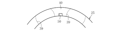
- the grease reservoir 50 is formed of a concave portion, and in the figure, is provided between the pockets 39 adjacent to each other in the circumferential direction on the axial one end face 36 side of the cage body 35 where the claw portion 38 is provided.
- it may be provided on the inner diameter side as shown in FIG. 7A or on the outer diameter side as shown in FIG. 7B. Further, although not shown, they may be provided on the inner diameter side and the outer diameter side.
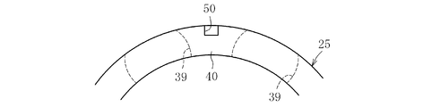
- FIG. 8 it is provided between the pockets 39 adjacent to each other in the circumferential direction on the side of the other axial end surface 40 of the cage main body 35 where the claw portion 38 is not provided.
- it may be provided on the inner diameter side as shown in FIG. 9A or on the outer diameter side as shown in FIG. 9B. Further, although not shown, they may be provided on the inner diameter side and the outer diameter side.
- the grease reservoir 50 by receiving the grease reservoir 50, the grease is accumulated in the grease reservoir 50, and the flow of grease to the rolling surfaces 22a and 23a of the rolling elements (balls) 24 can be reduced. Thereby, the stirring resistance of the grease can be reduced, and the torque can be further reduced.
- the size of the grease reservoir 50 can be variously changed according to the size of the cage itself, the material to be used, and the like. In this case, if it is too large, it will be inferior in strength, and if it is too small, the amount of grease will be small, and the grease flow to the rolling surfaces 22a, 23a cannot be reduced. For this reason, it can change variously in the range which is not inferior in strength and can reduce grease flow.
- the number of pockets 39 for holding the ball 24 may be the number of pockets 39. Although the number is 7 in the form, the number can be arbitrarily increased or decreased. Further, when the grease reservoir 50 is provided, it is provided between the pockets adjacent to each other in the circumferential direction, even if it is provided on either the cage inner diameter side or the cage outer diameter side. , May be provided between any pockets.
- a groove for thinning may be provided on the other axial end surface 40.
- the groove for meat thinning uniforms the cooling rate when forming the cage to prevent the occurrence of voids (cavities formed inside the molded product), sink marks (shrinkage distortion that appears on the outer surface of the molded product), warpage, etc. Will be provided for.
- the cage 25 may be made of metal such as carbon steel, spring steel, and stainless steel.
- the metal cage 4 is formed by cutting or the like.
- the resin cage 4 is molded by injection molding or the like.
- the ball bearing of the present invention using the cage according to the present invention can provide a ball bearing capable of obtaining a torque reduction effect by grease lubrication. For this reason, it is optimal as a ball bearing incorporated in a fan coupling device, an alternator, an idler pulley, an electromagnetic clutch for a car air conditioner, an electric fan motor, or the like.
Landscapes
- Engineering & Computer Science (AREA)
- General Engineering & Computer Science (AREA)
- Mechanical Engineering (AREA)
- Rolling Contact Bearings (AREA)
Abstract
グリース潤滑でトルク低減効果が得られる玉軸受用保持器及び玉軸受を提供する。 玉軸受用保持器は、環状の保持器本体35の軸方向一端面36に周方向に沿って所定ピッチで配設される凹部37を形成するとともに、凹部37の周方向に対向する開口端から一対の爪部38、38を突設して、凹部37と一対の爪部38、38とでボール24が収納されるポケット38を形成したものである。ポケット39のPCDを、ポケット38に収納されるボール24のPCDよりも小さく設定した。
Description
本発明は、玉を転動自在に保持する合成樹脂製の玉軸受用保持器、およびその保持器を外輪および内輪間に組み込んだ玉軸受に関する。
自動車の電装部品や補機部品、例えばファンカップリング装置、オルタネータ、アイドラプーリ、カーエアコン用電磁クラッチ、電動ファンモータ等に組み込まれる転がり軸受としては、エンジン出力で回転駆動する回転軸を静止部材に回転自在に支持するために、深溝玉軸受やアンギュラ玉軸受などの玉軸受が広く使用されている。
一般に、玉軸受は、図11に示すように、内輪1と、外輪2と、この内輪1と外輪2との間に介装されるボール3と、このボール3を保持する保持器4とを備える。そして、保持器には樹脂冠型保持器を使用する場合がある。この樹脂冠型保持器4は、耐摩耗性や耐焼き付き性等に優れた樹脂からなり、図12に示すように、環状の保持器本体5の軸方向一端面6に周方向に沿って所定ピッチで配設される凹部7を形成するとともに、この凹部7の周方向に対向する開口端から突出する一対の爪部8、8を設けて、凹部7と一対の爪部8、8とでボール3が収納されるポケット9を形成したものである。
ところで、転がり軸受においては、低トルク化が要求される。低トルク化仕様のものが種々提案されている(特許文献1及び特許文献2)。特許文献1および特許文献2では、保持器が一対のプレス形成板を締結手段にて締結されてなるものであり、各プレス形成板の内面にポケット用凹部が設けられ、この相対向するポケット用凹部で、転動体としてのボールが嵌合するポケットが形成される。そして、ポケット用凹部の内面に、潤滑剤(グリース)溜りとしての凹部等を設けたものである。
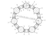
ところで、図12に示す樹脂冠型保持器4では、図13と図14に示すように、ポケット7のPCD(PPCD)と、ポケット7に収納されるボール3のPCD(BPCD)とが同一に設定される。また、ポケット径(DP)よりもボール径(DB)が小さい。
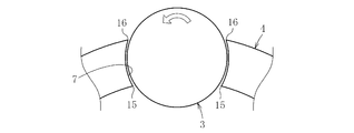
このため、ポケット7とボール3とは、図15に示す関係となる。すなわち、内径側のポケットエッジ部15及び外径側のポケットエッジ部16とボール3との隙間が生しる。このため、ポケットエッジ部15、16でボールに付着したグリースを掻き取りになってボール3と内輪の転走面との間、及びボールと外輪の転走面との間にグリースが介在されやすくなり、トルクが増加するおそれがある。
また、前記特許文献1および特許文献2では、ボールと保持器のポケットとの摺接面積を減少させることができて、低トルク化を図ることができる。しかしながら、グリース潤滑時は、凹部にグリースが溜り、常にグリースがボールに付着する状態となる。このため、ボール3と内輪の転走面との間、及びボールと外輪の転走面との間にグリースが介在されやすくなり、トルクが増加するおそれがある。
そこで、本発明は斯かる実情に鑑み、グリース潤滑でトルク低減効果が得られる玉軸受用保持器及び玉軸受を提供しようとするものである。
本発明の玉軸受用保持器は、環状の保持器本体の軸方向一端面に周方向に沿って所定ピッチで配設される凹部を形成するとともに、この凹部の周方向に対向する開口端から一対の爪部を突設して、前記凹部と一対の爪部とでボールが収納されるポケットを形成した玉軸受用保持器であって、前記ポケットのPCDを、ポケットに収納されるボールのPCDよりも小さく設定したものである。
本発明の玉軸受用保持器によれば、ポケットのPCDを、ポケットに収納されるボールのPCDよりも小さく設定したことによって、ポケットをボールに対して内径側に位置させることができる。これによって、外径側のポケットエッジ部がボールに近接した状態(ボールをポケットの外径側で抱え込む状態)となって、ボールに付着したグリースを掻き取ることができる。
前記ポケットのPCDが、ボールのPCDの0.9~0.99である場合において、ポケット径がボール径の1.06倍以下であるのが好ましい。1.06倍を超えると、ポケット径が大きくなりすぎてガタが生じるおそれがある。
前記ポケットのPCDが、ボールのPCDの0.9~0.99である場合において、ポケット径がボール径の1.03倍以上であるのが好ましい。1.03倍未満では、ポケット径が小さくなりすぎてボールとポケットとの間の隙間が小さくなって、異常摩耗や応力が大となるおそれがある。
保持器本体の爪部が設けられる軸方向一端面側において、周方向に沿って隣合うポケット間の内径側及び/又は外径側にグリース溜りを設けることができる。
保持器本体の爪部を有さない軸方向他端面側において、周方向に沿って隣合うポケット間の内径側及び/又は外径側にグリース溜りを設けることができる。
このように、グリース溜りを受けることによって、このグリース溜りにグリースが溜まって転動体(ボール)の転走面へのグリースの流動を減らすことができる。これによって、グリースの攪拌抵抗を低減できる。
保持器材料がPA66(ポリアミド66)であったり、PA46(ポリアミド46)であったり、PA9T(ポリアミド9T)であったり、PA11(ポリアミド11)であったり、PA6(ポリアミド6)であったりする。このように、保持器材料としては、引張伸び,引張強さ,耐衝撃性,耐摩耗性,潤滑性等に優れたポリアミド樹脂等が好ましい。
本発明の玉軸受は、内輪と、外輪と、この内輪と外輪との間に介装されるボールと、このボールを保持する保持器とを備えた玉軸受において、前記保持器に前記玉軸受用保持器を用いたものである。
本発明の玉軸受用保持器は、外径側のポケットエッジ部がボールに近接した状態(ボールをポケットの外径側で抱え込む状態)となって、ボールに付着したグリースを掻き取ることができるので、グリース潤滑でトルク低減効果を得ることができる。
前記ポケットのPCDが、ボールのPCDの0.9~0.99である場合において、ポケット径がボール径の1.06倍以下であるのが好ましく、また、前記ポケットのPCDが、ボールのPCDの0.9~0.99である場合において、ポケット径がボール径の1.03倍以上であるのが好ましい。ボール径の1.06以下であれば、ガタを少なくできて、高精度の回転を得ることができる。1.03倍以上であれば、異常摩耗や応力が大となるおそれがなく、長期にわたって安定した回転を得ることができる。
グリース溜りを受けることによって、グリースの攪拌抵抗を低減でき、より一層低トルク化を達成できる。
保持器材料としては、引張伸び,引張強さ,耐衝撃性,耐摩耗性,潤滑性等に優れたポリアミド樹脂を用いることができ、高品質な保持器を提供できる。
本発明の玉軸受では、グリース潤滑でトルク低減効果を得ることができる玉軸受を提供することができる。このため、ファンカップリング装置、オルタネータ、アイドラプーリ、カーエアコン用電磁クラッチ、電動ファンモータ等に組み込まれる玉軸受として最適となる。
以下、本発明の実施形態を図面に従って説明する。
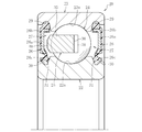
図1~図3は本発明にかかる玉軸受用保持器を示し、この玉軸受用保持器は、図4に示す玉軸受に使用される。この図例の玉軸受は、自動車の電装部品や補機部品、例えばファンカップリング装置、オルタネータ、アイドラプーリ、カーエアコン用電磁クラッチ、電動ファンモータ等に組み込まれる。
この実施形態の玉軸受20は、外周面に内側転走面22aが形成された内輪22と、その内輪22の外側に配置され、内周面に外側転走面23aが形成された外輪23と、内輪22の内側転走面22aと外輪23の外側転走面23aとの間に転動自在に介在された複数のボール(玉)24と、内輪22と外輪23との間に配され、各ボール24を円周方向等間隔に保持する保持器25と、内輪22と外輪23間の軸方向両側に配され、その内輪22と外輪23間に形成された環状空間27を密封するシール部材26とで主要部が構成されている。このシール部材26により密封された環状空間27にグリース等の潤滑剤を封入することにより、保持器25のポケット内でボール24がスムーズに転動するようにしている。
この実施形態では、外輪23がハウジングなどの静止部材に装着され、内輪22がエンジン出力で回転駆動する回転軸に装着される。シール部材26は、環状の芯金26aとこの芯金26aに一体に固着されるゴム状部材26bとで構成され、外輪23の内周面に形成されたシール取付溝29に外周部が嵌合状態に固定される。内輪22はシール部材26の内周部に対応する位置に、円周溝からなるシール溝30が形成され、シール部材26の内周側端26cに形成されたシールリップ31が内輪1のシール溝30に摺接する。なお、この実施形態では内輪回転タイプを例示しているが、内輪22がシャフトなどの静止部材に装着され、外輪3が回転軸に装着された外輪回転タイプにも適用可能である。
この玉軸受20の運転中、シール部材26の先端のシールリップ31が内輪22の外周端部に摺接した状態を維持しながら、内輪22が回転する。これにより、水やダスト等の異物が軸受内部に侵入したり、あるいは、軸受内部から潤滑剤が外部へ漏れたりすることを未然に防止するようにしている。
この保持器25は、図1~図3に示すように、軸方向一端面36に周方向に沿って所定ピッチで配設される凹部37を形成した環状の保持器本体35と、この保持器本体35の凹部37の周方向に対向する開口端から突出する爪部38とを備える。そして、凹部37と、この開口端から突出する一対の爪部38、38とで、前記ボール24が保持されるポケット39が構成される。
保持器25は、この種の一般的に使用される耐摩耗性や耐焼き付等に優れた樹脂、例えばポリエチレン、ポリアミド、ポリアセタール、ポリエチレンテレフタレート、ポリブチレンテレフタレート、ポリカーボネート、ポリフェニレンサルファイド、ポリエーテルサルフォン、ポリエーテルイミド、ポリアミドイミド、ポリエーテルエーテルケトン、熱可塑性ポリイミド、熱硬化性ポリイミド、エポキシ樹脂、フェノール樹脂等の合成樹脂で形成することができる。さらには、ポリアミド、ポリフェニレンサルファイド、あるいはポリエーテルエーテルケトン等の熱可塑性樹脂をベースとして、強度向上と寸法安定性のために、ガラス繊維を添加したものも採用することができる。
しかしながら、本発明においては、保持器25の保持器材料として、引張伸び,引張強さ,耐衝撃性,耐摩耗性,潤滑性等に優れたポリアミド樹脂を用いるのが好ましい。ポリアミド樹脂としては、PA66(ポリアミド66)であったり、PA46(ポリアミド46)であったり、PA9T(ポリアミド9T)であったり、PA11(ポリアミド11)であったり、PA6(ポリアミド6)であったりする。このように、本発明では、保持器材料として、引張伸び,引張強さ,耐衝撃性,耐摩耗性,潤滑性等に優れたポリアミド樹脂を用いることができ、高品質な保持器を提供できる。なお、外輪23、内輪22、ボール24は、例えば軸受鋼、浸炭鋼等の金属で形成される。
また、この玉軸受に充填されるグリースは、基油、増ちょう剤及び添加剤から成る半固体状の潤滑剤である。潤滑グリースを構成する基油としては、例えば、パラフィン系鉱油、ナフテン系鉱油などの鉱油、ポリブデン、ポリ-α-オレフィン、アルキルベンゼン、アルキルナフタレン、脂環式化合物等の炭化水素系合成油、または、天然油脂やポリオールエステル油、リン酸エステル、ジエステル油、ポリグリコール油、シリコーン油、ポリフェニルエーテル油、アルキルジフェニルエーテル油、フッ素化油等の非炭化水素系合成油等、一般に潤滑グリースの基油として使用されている油であれば特に限定することなく使用できる。
また、増ちょう剤としては、アルミニウム石けん、リチウム石けん、ナトリウム石けん、複合リチウム石けん、複合カルシウム石けん、複合アルミニウム石けんなどの金属石けん系増ちょう剤、ジウレア化合物、ポリウレア化合物等のウレア系化合物が挙げられる。これらの増ちょう剤は、単独または2種類以上組み合せて用いてもよい。
潤滑グリース用の公知の添加剤としては、例えば極圧剤、アミン系、フェノール系等の酸化防止剤、ベンゾトリアゾールなどの金属不活性剤、ポリメタクリレート、ポリスチレン等の粘度指数向上剤、二硫化モリブデン、グラファイト等の固体潤滑剤等が挙げられる。これらを単独または2種類以上組み合せて添加できる。
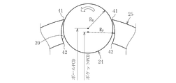
保持器25においては、ポケット39のPCDを、ポケット39に収納されるボール24のPCDよりも小さく設定したものである。すなわち、図1と図2に示すように、ポケットPCDをPPCDとし、ボールPCDをBPCDとした場合に、PPCD<BPCDとなる。この場合、ポケット39のPCDが、ボールPCDの0.9~0.99である場合(PPCD=0.9BPCD~0.99BPCDである場合)において、ポケット径DPがボール径DBの1.06倍以下とし、ポケット径DPがボール径DBの1.03倍以上とする。
ここで、図5に示すように、ポケットPCDとは、保持器ポケットのアール中心(RP)と軸受の中心までの長さ(半径)の2倍の長さ(直径)のことである。また、ボールPCDとは、ボールの中心(RB)と軸受の中心までの長さ(半径)の2倍の長さ(直径)のことである。ボール24とポケット39との関係を前記のように構成することによって、図1に示すように、この保持器を爪部38側から見た場合、ポケット39がボール24に対して内径側に位置させることができる。これによって、図5に示すように、外径側のポケットエッジ部41がボール24に近接した状態(ボール24をポケットの外径側で抱え込む状態)となって、ボール24に付着したグリースを掻き取ることができる。なお、内径側のポケットエッジ部42がボール24と離間した状態となって、ボール24に付着したグリースを掻き取りにくくなっている。なお、図5の矢印はボール24の回転方向を示している。
本発明では、外径側のポケットエッジ部41がボールに近接した状態(ボールをポケットの外径側で抱え込む状態)となって、ボール24に付着したグリースを掻き取ることができるので、グリース潤滑でトルク低減効果を得ることができる。なお、外径側のポケットエッジ部42がボール24と離間した状態となって、掻き取りにくくなっているので、グリース漏れがし難い状態となる。
前記ポケットPCDが、ボールPCDの0.9~0.99である場合において、ポケット径がボール径の1.06倍以下であるのが好ましく、また、前記ポケットPCDが、ボールPCDの0.9~0.99である場合において、ポケット径DPがボール径DBの1.03倍以上であるのが好ましい。ボール径DBの1.06以下であれば、ガタを少なくできて、高精度の回転を得ることができる。1.03倍以上であれば、異常摩耗や応力が大となるおそれがなく、長期にわたって安定した回転を得ることができる。
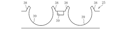
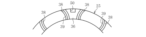
ところで、保持器25には、図6に示すように、ポケットエッジ部41にて掻き取れたグリースを溜めるグリース溜り50を設けるのが好ましい。グリース溜り50は凹部からなり、図では、爪部38が設けられる保持器本体35の軸方向一端面36側に、周方向に隣合うポケット39間に設けたものである。この場合、図7Aに示すように内径側に設けても、図7Bに示すように外径側に設けてもよい。さらには、図示省略するが、内径側及び外径側に設けるようにしてもよい。
図8では、爪部38が設けられていない保持器本体35の軸方向他端面40側に、周方向に隣合うポケット39間に設けたものである。この場合も、図9Aに示すように内径側に設けても、図9Bに示すように外径側に設けてもよい。さらには、図示省略するが、内径側及び外径側に設けるようにしてもよい。
このように、グリース溜り50を受けることによって、このグリース溜り50にグリースが溜まって転動体(ボール)24の転走面22a、23aへのグリースの流動を減らすことができる。これによって、グリースの攪拌抵抗を低減でき、より一層低トルク化を達成できる。
ところで、このグリース溜り50の大きさとしては、保持器自体の大きさ、使用する材質等に応じて、種々変更することができる。この場合、大きすぎれば、強度的に劣ることになり、小さすぎれば、グリース溜り量が少なく、転走面22a、23aへのグリース流動を減らすことができない。このため、強度的に劣らず、しかもグリース流動を減らすことができる範囲で種々変更することができる。
以上、本発明の実施形態につき説明したが、本発明は前記実施形態に限定されることなく種々の変形が可能であって、例えば、ボール24を保持するためのポケット39の数として、前記実施形態では7個であったが、その数は任意に増減できる。また、グリース溜り50を設ける場合、保持器内径側又は保持器外径側のいずれの側に設けたとしても、周方向に隣合うポケット間に設けることになるが、全ポケット間に設けても、任意のポケット間に設けてもよい。
また、軸方向他端面40に肉ぬすみ用の溝を設けてもよい。肉ぬすみ用の溝は、保持器成形時の冷却速度を均一化してボイド(成形品の内部にできた空洞)やヒケ(成形品の外面に現れる収縮歪)やそり等の発生を防止する等のために設けることになる。
保持器25として、炭素鋼、ばね鋼、ステンレス鋼等の金属製であってもよい。金属製の保持器4では切削加工等によって成形される。前記実施形態のように、樹脂製の保持器4では射出成形等にて成形される。
次に、ポケットPCDとボールPCDとが同一の従来の保持器を用いた玉軸受(従来品)と、ポケットPCDを、ポケット39に収納されるボールPCDよりも小さく設定した保持器を用いた玉軸受(本発明品)とのトルクを比較した。軸受としてNTN社製の6203LLBを用い、グリースとして日本グリース社のME-1を用いた。また、回転速度を1000r/minとし、荷重Faを29.4Nとし、雰囲気温度として常温とした。本発明品のポケットPCDとボールPCDとの差を0.7mmとした。トルク測定結果を図10に示す。この図10からわかるように、本発明品はグリース潤滑でトルク低減効果を得ることができる。
本発明に係る保持器を用いた本発明の玉軸受では、グリース潤滑でトルク低減効果を得ることができる玉軸受を提供することができる。このため、ファンカップリング装置、オルタネータ、アイドラプーリ、カーエアコン用電磁クラッチ、電動ファンモータ等に組み込まれる玉軸受として最適となる。
35 保持器本体
36 軸方向一端面
37 凹部
38 爪部
39 ポケット
40 軸方向他端面
50 グリース溜り
36 軸方向一端面
37 凹部
38 爪部
39 ポケット
40 軸方向他端面
50 グリース溜り
Claims (15)
- 環状の保持器本体の軸方向一端面に周方向に沿って所定ピッチで配設される凹部を形成するとともに、この凹部の周方向に対向する開口端から一対の爪部を突設して、前記凹部と一対の爪部とでボールが収納されるポケットを形成した玉軸受用保持器であって、
前記ポケットのPCDを、ポケットに収納されるボールのPCDよりも小さく設定したことを特徴とする玉軸受用保持器。 - 前記ポケットのPCDが、ボールのPCDの0.9~0.99である場合において、ポケット径がボール径の1.06倍以下であることを特徴とする請求項1に記載の玉軸受用保持器。
- 前記ポケットのPCDが、ボールのPCDの0.9~0.99である場合において、ポケット径がボール径の1.03倍以上であることを特徴とする請求項1に記載の玉軸受用保持器。
- 保持器本体の爪部が設けられる軸方向一端面側において、周方向に沿って隣合うポケット間の内径側にグリース溜りを設けたことを特徴とする請求項1~請求項3のいずれか1項に記載の玉軸受用保持器。
- 保持器本体の爪部が設けられる軸方向一端面側において、周方向に沿って隣合うポケット間の外径側にグリース溜りを設けたことを特徴とする請求項1~請求項3のいずれか1項に記載の玉軸受用保持器。
- 保持器本体の爪部が設けられる軸方向一端面側において、周方向に沿って隣合うポケット間の内径側及び外径側にグリース溜りを設けたことを特徴とする請求項1~請求項3のいずれか1項に記載の玉軸受用保持器。
- 保持器本体の爪部を有さない軸方向他端面側において、周方向に沿って隣合うポケット間の内径側にグリース溜りを設けたことを特徴とする請求項1~請求項3のいずれか1項に記載の玉軸受用保持器。
- 保持器本体の爪部を有さない軸方向他端面側において、周方向に沿って隣合うポケット間の外径側にグリース溜りを設けたことを特徴とする請求項1~請求項3のいずれか1項に記載の玉軸受用保持器。
- 保持器本体の爪部を有さない軸方向他端面側において、周方向に沿って隣合うポケット間に内径側及び外径側にグリース溜りを設けたことを特徴とする請求項1~請求項3のいずれか1項に記載の玉軸受用保持器。
- 保持器材料がPA66であることを特徴とする請求項1~請求項9のいずれか1項に記載の玉軸受用保持器。
- 保持器材料がPA46であることを特徴とする請求項1~請求項9のいずれか1項に記載の玉軸受用保持器。
- 保持器材料がPA9Tであることを特徴とする請求項1~請求項9のいずれか1項に記載の玉軸受用保持器。
- 保持器材料がPA11であることを特徴とする請求項1~請求項9のいずれか1項に記載の玉軸受用保持器。
- 保持器材料がPA6であることを特徴とする請求項1~請求項9のいずれか1項に記載の玉軸受用保持器。
- 内輪と、外輪と、この内輪と外輪との間に介装されるボールと、このボールを保持する保持器とを備えた玉軸受において、前記保持器に前記請求項1~請求項13のいずれか1項に記載の玉軸受用保持器を用いたことを特徴とする玉軸受。
Priority Applications (3)
| Application Number | Priority Date | Filing Date | Title |
|---|---|---|---|
| CN201180046906.1A CN103124855B (zh) | 2010-09-28 | 2011-08-29 | 球轴承用保持架及球轴承 |
| EP11828667.3A EP2623801A4 (en) | 2010-09-28 | 2011-08-29 | Retainer for ball bearing, and ball bearing |
| US13/820,637 US8876395B2 (en) | 2010-09-28 | 2011-08-29 | Ball bearing with retainer |
Applications Claiming Priority (2)
| Application Number | Priority Date | Filing Date | Title |
|---|---|---|---|
| JP2010-217029 | 2010-09-28 | ||
| JP2010217029A JP5615649B2 (ja) | 2010-09-28 | 2010-09-28 | 玉軸受 |
Publications (1)
| Publication Number | Publication Date |
|---|---|
| WO2012043106A1 true WO2012043106A1 (ja) | 2012-04-05 |
Family
ID=45892580
Family Applications (1)
| Application Number | Title | Priority Date | Filing Date |
|---|---|---|---|
| PCT/JP2011/069374 Ceased WO2012043106A1 (ja) | 2010-09-28 | 2011-08-29 | 玉軸受用保持器及び玉軸受 |
Country Status (5)
| Country | Link |
|---|---|
| US (1) | US8876395B2 (ja) |
| EP (1) | EP2623801A4 (ja) |
| JP (1) | JP5615649B2 (ja) |
| CN (1) | CN103124855B (ja) |
| WO (1) | WO2012043106A1 (ja) |
Families Citing this family (14)
| Publication number | Priority date | Publication date | Assignee | Title |
|---|---|---|---|---|
| DE102013212962A1 (de) * | 2013-07-03 | 2015-01-08 | Aktiebolaget Skf | Lagerkäfig für verlängerte Fettgebrauchsdauer |
| JP6582566B2 (ja) | 2015-06-03 | 2019-10-02 | 株式会社ジェイテクト | 転がり軸受 |
| JP6866564B2 (ja) * | 2016-01-19 | 2021-04-28 | 株式会社ジェイテクト | 玉軸受 |
| JP6957836B2 (ja) | 2016-01-26 | 2021-11-02 | 株式会社ジェイテクト | 転がり軸受 |
| JP2018028377A (ja) * | 2016-08-19 | 2018-02-22 | ミネベアミツミ株式会社 | ターボチャージャー用玉軸受ユニット |
| JP6874455B2 (ja) * | 2017-03-22 | 2021-05-19 | 株式会社ジェイテクト | 転がり軸受 |
| JP6946697B2 (ja) | 2017-03-31 | 2021-10-06 | 株式会社ジェイテクト | 転がり軸受 |
| JP6950430B2 (ja) | 2017-10-04 | 2021-10-13 | 株式会社ジェイテクト | 玉軸受 |
| CN213954169U (zh) * | 2018-02-01 | 2021-08-13 | 日本精工株式会社 | 滚珠轴承 |
| CN112240347B (zh) * | 2019-07-17 | 2024-10-15 | 斯凯孚公司 | 轴承保持架及其应用 |
| JP7591947B2 (ja) * | 2021-03-04 | 2024-11-29 | Ntn株式会社 | 保持器及び玉軸受 |
| JPWO2023157429A1 (ja) | 2022-02-17 | 2023-08-24 | ||
| US12247620B2 (en) | 2022-02-17 | 2025-03-11 | Nsk Ltd. | Retainer |
| WO2023181369A1 (ja) * | 2022-03-25 | 2023-09-28 | 株式会社ジェイテクト | 転がり軸受、及び、転がり軸受用の保持器 |
Citations (4)
| Publication number | Priority date | Publication date | Assignee | Title |
|---|---|---|---|---|
| JPS58195118U (ja) * | 1982-06-23 | 1983-12-26 | 日本精工株式会社 | 転動体案内用保持器 |
| JPH09317775A (ja) | 1996-05-31 | 1997-12-09 | Koyo Seiko Co Ltd | 玉軸受用波形保持器 |
| JP2003013962A (ja) | 2001-06-29 | 2003-01-15 | Nsk Ltd | 玉軸受 |
| JP2003214437A (ja) * | 2002-01-18 | 2003-07-30 | Koyo Seiko Co Ltd | 玉軸受 |
Family Cites Families (19)
| Publication number | Priority date | Publication date | Assignee | Title |
|---|---|---|---|---|
| JPS58195118A (ja) | 1982-05-10 | 1983-11-14 | Hitachi Ltd | コイル固定方法 |
| JP3654924B2 (ja) * | 1994-03-24 | 2005-06-02 | 株式会社東芝 | レーザービームプリンタ用スキャナモータ |
| US5642945A (en) * | 1994-08-26 | 1997-07-01 | Koyo Seiko Co., Ltd. | Bearing assembly |
| JPH0996315A (ja) * | 1995-09-29 | 1997-04-08 | Ntn Corp | 玉軸受用樹脂保持器 |
| JP3564254B2 (ja) * | 1997-01-27 | 2004-09-08 | 光洋精工株式会社 | 玉軸受用プラスチック製冠型保持器 |
| JP3751771B2 (ja) * | 1999-06-08 | 2006-03-01 | 光洋精工株式会社 | 玉軸受 |
| JP2001027248A (ja) * | 1999-07-14 | 2001-01-30 | Minebea Co Ltd | 転がり軸受用保持器 |
| FR2796680B1 (fr) * | 1999-07-23 | 2001-09-14 | Skf France | Dispositif de cage pour roulement a billes et roulement associe |
| JP4058662B2 (ja) * | 2000-02-18 | 2008-03-12 | ミネベア株式会社 | ベアリングリテーナ |
| FR2821651B1 (fr) * | 2001-03-01 | 2004-05-14 | Roulements Soc Nouvelle | Cage a reserve de substance lubrifiante |
| JP2003287032A (ja) * | 2002-03-28 | 2003-10-10 | Nsk Ltd | 玉軸受用プラスチック製冠型保持器 |
| JP4055938B2 (ja) * | 2002-04-18 | 2008-03-05 | ミネベア株式会社 | ラジアルボールベアリングのリテーナ |
| JP2005214259A (ja) * | 2004-01-28 | 2005-08-11 | Nsk Ltd | 玉軸受及びオルタネータ用玉軸受 |
| JP2008032218A (ja) * | 2006-06-30 | 2008-02-14 | Ntn Corp | 耐熱・耐油性転がり軸受および冷凍機の圧縮機用転がり軸受 |
| CN101479493B (zh) * | 2006-06-30 | 2012-06-27 | Ntn株式会社 | 耐热、耐油性滚动轴承以及冷冻机的压缩机用滚动轴承 |
| JP2008144876A (ja) * | 2006-12-11 | 2008-06-26 | Nsk Ltd | 保持器 |
| FR2911934B1 (fr) * | 2007-01-26 | 2009-09-18 | Skf Ab | Cage pour roulement a billes |
| WO2010067852A1 (ja) * | 2008-12-10 | 2010-06-17 | 日本精工株式会社 | 玉軸受及びハイブリッド車用変速機 |
| JP5272737B2 (ja) * | 2009-01-05 | 2013-08-28 | 日本精工株式会社 | 冠型保持器及び玉軸受 |
-
2010
- 2010-09-28 JP JP2010217029A patent/JP5615649B2/ja not_active Expired - Fee Related
-
2011
- 2011-08-29 US US13/820,637 patent/US8876395B2/en not_active Expired - Fee Related
- 2011-08-29 CN CN201180046906.1A patent/CN103124855B/zh not_active Expired - Fee Related
- 2011-08-29 WO PCT/JP2011/069374 patent/WO2012043106A1/ja not_active Ceased
- 2011-08-29 EP EP11828667.3A patent/EP2623801A4/en not_active Withdrawn
Patent Citations (4)
| Publication number | Priority date | Publication date | Assignee | Title |
|---|---|---|---|---|
| JPS58195118U (ja) * | 1982-06-23 | 1983-12-26 | 日本精工株式会社 | 転動体案内用保持器 |
| JPH09317775A (ja) | 1996-05-31 | 1997-12-09 | Koyo Seiko Co Ltd | 玉軸受用波形保持器 |
| JP2003013962A (ja) | 2001-06-29 | 2003-01-15 | Nsk Ltd | 玉軸受 |
| JP2003214437A (ja) * | 2002-01-18 | 2003-07-30 | Koyo Seiko Co Ltd | 玉軸受 |
Non-Patent Citations (1)
| Title |
|---|
| See also references of EP2623801A4 |
Also Published As
| Publication number | Publication date |
|---|---|
| US20130163909A1 (en) | 2013-06-27 |
| EP2623801A4 (en) | 2017-01-25 |
| JP2012072815A (ja) | 2012-04-12 |
| CN103124855A (zh) | 2013-05-29 |
| CN103124855B (zh) | 2017-02-08 |
| EP2623801A1 (en) | 2013-08-07 |
| US8876395B2 (en) | 2014-11-04 |
| JP5615649B2 (ja) | 2014-10-29 |
Similar Documents
| Publication | Publication Date | Title |
|---|---|---|
| JP5615649B2 (ja) | 玉軸受 | |
| CN102422037B (zh) | 传动装置用轴承 | |
| JP2012163172A (ja) | 玉軸受用保持器および玉軸受 | |
| US8961023B2 (en) | Ball bearing retainer and ball bearing | |
| US9366292B2 (en) | Retainer for ball bearing, and ball bearing | |
| JP5872172B2 (ja) | 玉軸受用保持器および玉軸受 | |
| JP2012107674A (ja) | 玉軸受 | |
| JP5687012B2 (ja) | 密封型転がり軸受 | |
| JP5623312B2 (ja) | 玉軸受用保持器および玉軸受 | |
| JP5863284B2 (ja) | 玉軸受用保持器および玉軸受 | |
| JP2012057703A (ja) | 軸受用保持器および転がり軸受 | |
| JP6125185B2 (ja) | ウォータポンププーリユニット | |
| JP2013142407A (ja) | 玉軸受用保持器および玉軸受 | |
| WO2023149266A1 (ja) | 玉軸受 | |
| JP2013200006A (ja) | 玉軸受およびその保持器 | |
| WO2016152696A1 (ja) | 転がり軸受 | |
| JP2018135958A (ja) | トランスミッション用転がり軸受装置 | |
| JP2012172834A (ja) | 密封型転がり軸受 | |
| JP2015232400A (ja) | 玉軸受用保持器および玉軸受 | |
| JP2012251635A (ja) | 玉軸受用保持器および玉軸受 | |
| WO2023189430A1 (ja) | 玉軸受 | |
| WO2023189431A1 (ja) | 玉軸受 | |
| WO2024241906A1 (ja) | 玉軸受 | |
| WO2024018952A1 (ja) | 玉軸受 | |
| JP2002310255A (ja) | 有限ストローク型ボールねじ装置 |
Legal Events
| Date | Code | Title | Description |
|---|---|---|---|
| WWE | Wipo information: entry into national phase |
Ref document number: 201180046906.1 Country of ref document: CN |
|
| 121 | Ep: the epo has been informed by wipo that ep was designated in this application |
Ref document number: 11828667 Country of ref document: EP Kind code of ref document: A1 |
|
| WWE | Wipo information: entry into national phase |
Ref document number: 13820637 Country of ref document: US Ref document number: 2011828667 Country of ref document: EP |
|
| NENP | Non-entry into the national phase |
Ref country code: DE |