WO2012043268A1 - 車体前部構造 - Google Patents
車体前部構造 Download PDFInfo
- Publication number
- WO2012043268A1 WO2012043268A1 PCT/JP2011/071184 JP2011071184W WO2012043268A1 WO 2012043268 A1 WO2012043268 A1 WO 2012043268A1 JP 2011071184 W JP2011071184 W JP 2011071184W WO 2012043268 A1 WO2012043268 A1 WO 2012043268A1
- Authority
- WO
- WIPO (PCT)
- Prior art keywords
- cover
- maintenance lid
- rotation support
- engine
- vehicle body
- Prior art date
- Legal status (The legal status is an assumption and is not a legal conclusion. Google has not performed a legal analysis and makes no representation as to the accuracy of the status listed.)
- Ceased
Links
Images


Classifications
-
- B—PERFORMING OPERATIONS; TRANSPORTING
- B62—LAND VEHICLES FOR TRAVELLING OTHERWISE THAN ON RAILS
- B62D—MOTOR VEHICLES; TRAILERS
- B62D35/00—Vehicle bodies characterised by streamlining
- B62D35/02—Streamlining the undersurfaces
-
- B—PERFORMING OPERATIONS; TRANSPORTING
- B62—LAND VEHICLES FOR TRAVELLING OTHERWISE THAN ON RAILS
- B62D—MOTOR VEHICLES; TRAILERS
- B62D25/00—Superstructure or monocoque structure sub-units; Parts or details thereof not otherwise provided for
- B62D25/08—Front or rear portions
- B62D25/10—Bonnets or lids, e.g. for trucks, tractors, busses, work vehicles
-
- B—PERFORMING OPERATIONS; TRANSPORTING
- B62—LAND VEHICLES FOR TRAVELLING OTHERWISE THAN ON RAILS
- B62D—MOTOR VEHICLES; TRAILERS
- B62D25/00—Superstructure or monocoque structure sub-units; Parts or details thereof not otherwise provided for
- B62D25/20—Floors or bottom sub-units
-
- B—PERFORMING OPERATIONS; TRANSPORTING
- B62—LAND VEHICLES FOR TRAVELLING OTHERWISE THAN ON RAILS
- B62D—MOTOR VEHICLES; TRAILERS
- B62D25/00—Superstructure or monocoque structure sub-units; Parts or details thereof not otherwise provided for
- B62D25/20—Floors or bottom sub-units
- B62D25/2072—Floor protection, e.g. from corrosion or scratching
-
- B—PERFORMING OPERATIONS; TRANSPORTING
- B62—LAND VEHICLES FOR TRAVELLING OTHERWISE THAN ON RAILS
- B62D—MOTOR VEHICLES; TRAILERS
- B62D25/00—Superstructure or monocoque structure sub-units; Parts or details thereof not otherwise provided for
- B62D25/24—Superstructure sub-units with access or drainage openings having movable or removable closures; Sealing means therefor
-
- B—PERFORMING OPERATIONS; TRANSPORTING
- B60—VEHICLES IN GENERAL
- B60R—VEHICLES, VEHICLE FITTINGS, OR VEHICLE PARTS, NOT OTHERWISE PROVIDED FOR
- B60R19/00—Wheel guards; Radiator guards, e.g. grilles; Obstruction removers; Fittings damping bouncing force in collisions
- B60R19/02—Bumpers, i.e. impact receiving or absorbing members for protecting vehicles or fending off blows from other vehicles or objects
- B60R19/24—Arrangements for mounting bumpers on vehicles
-
- Y—GENERAL TAGGING OF NEW TECHNOLOGICAL DEVELOPMENTS; GENERAL TAGGING OF CROSS-SECTIONAL TECHNOLOGIES SPANNING OVER SEVERAL SECTIONS OF THE IPC; TECHNICAL SUBJECTS COVERED BY FORMER USPC CROSS-REFERENCE ART COLLECTIONS [XRACs] AND DIGESTS
- Y02—TECHNOLOGIES OR APPLICATIONS FOR MITIGATION OR ADAPTATION AGAINST CLIMATE CHANGE
- Y02T—CLIMATE CHANGE MITIGATION TECHNOLOGIES RELATED TO TRANSPORTATION
- Y02T10/00—Road transport of goods or passengers
- Y02T10/80—Technologies aiming to reduce greenhouse gasses emissions common to all road transportation technologies
- Y02T10/88—Optimized components or subsystems, e.g. lighting, actively controlled glasses
Definitions
- the present invention relates to a vehicle body front structure in which an engine under cover is provided below the vehicle body front.
- an undercover that covers the lower surface of the vehicle body.
- This under cover is provided, for example, to protect the engine room and the like from muddy water and stepping stones raised by the tire and to improve the aerodynamic characteristics by covering the unevenness on the lower surface of the vehicle.
- Patent Document 1 discloses providing an inspection lid 2 that is slidably housed in an undercover 1 that covers the lower surface of the engine. ing. Further, in Patent Document 2, in order to ensure the rigidity and strength of the resin undercover, a reinforcing aggregate is stored in the storage recess of the cover body, and the aggregate is prevented from being plastically deformed. It has been proposed to include deformation preventing means.
- the aggregate extends into the opening of the subframe, and an engine, a transmission, or the like is disposed above the opening of the subframe.
- the under cover disclosed in Patent Document 2 if an attempt is made to provide a maintenance lid that can be opened and closed with respect to the under cover, the aggregate may not be accommodated in the accommodating recess of the cover body. is there.
- the present invention provides a vehicle body front structure in which an engine under cover that covers a lower side of a vehicle body front portion is provided, and a maintenance lid is provided at a central portion of the engine under cover,
- the maintenance lid is a pair of side rotation support portions provided on the left and right sides of the front edge portion of the maintenance lid, and a center provided between the pair of side rotation support portions on the rear side of the side rotation support portions.
- a rotation support portion, wherein the side rotation support portion has an opening that can be locked to a claw portion having an L-shaped cross section provided in the engine undercover, and the center rotation support portion includes the engine undercover.
- the sliding movement locks the maintenance lid, characterized in that it is rotation of the pair of side rotating support as a fulcrum.
- the sliding operation of the maintenance lid is locked by the side rotation support portion and the center rotation support portion,
- the maintenance lid is rotated about the pair of side rotation support portions. Therefore, the support lid can be increased during sliding when a high load is applied by the operator, compared to when the maintenance lid is rotated only by the gravity of the maintenance lid. Can be reduced in weight.
- the maintenance cover can be suspended from the engine under cover by rotating the lightweight maintenance cover after sliding it during maintenance, and the entire maintenance cover is removed from the engine under cover. No maintenance work can be performed. Furthermore, in the present invention, the space for pulling out the maintenance lid as in the prior art becomes unnecessary, so that the work space is not enlarged and the maintainability can be further improved.
- the rear edge claw is provided on the engine under cover side, and the rear edge claw is provided so as to be able to lock a rectangular opening formed at the rear edge of the maintenance lid.
- the front edge portion of the maintenance lid is provided so that the side rotation support portion is locked by a claw portion having a substantially L-shaped cross section and is placed on the upper surface of the engine undercover, and the rear edge portion of the maintenance lid is Since it is locked by the rear edge claw on the engine under cover side, the fastening operation for fastening the maintenance cover to the engine under cover in a state where the maintenance cover is prevented from falling can be easily performed.
- the engine under cover has a semi-cage-shaped protrusion that avoids interference with the jack support at the front edge, and the side wall on which the locking portion of the central rotation support is locked
- the side wall becomes a curved surface and the strength is high, and the locking strength for locking the locking portion can be increased.
- the locking strength can be further increased by providing the locking ribs on the peripheral edge of the opening of the side wall.
- the engaging portion of the central rotation support portion is engaged with the wall surface of the side wall until the initial stage of the rotation operation of the maintenance lid, so that the operator can be operated at the initial stage of the rotation operation of the maintenance lid.
- the load applied to the side rotation support portion can be reduced by pressing the locking portion of the central rotation support portion so as to kick up the opening periphery of the side wall.
- the engine undercover includes a front cover portion between a front portion and a rear portion of a subframe and a rear cover portion between the subframe and the floor frame, and the front cover portion and the rear cover portion are included.
- the front cover part and the rear cover part can be opened and closed independently via a broken line part formed at the boundary with the cover part, so that the entire engine under cover is not removed and maintenance is improved. Can be made.
- the present invention even when a maintenance lid is provided at the center of the front portion of the resin engine undercover, the left and right side portions along the vehicle width direction adjacent to the maintenance lid in addition, a metal reinforcing member extending along the longitudinal direction of the vehicle body is disposed.
- the desired rigidity and strength of the engine undercover is ensured by the metal reinforcing member, and deformation due to the negative pressure on the lower side of the engine undercover during high-speed traveling is prevented, resulting in aerodynamic performance. It can contribute greatly.
- the engine undercover is provided with a rib standing in an interference area with the metal sub-frame disposed on the upper side of the metal reinforcing member, and the rib is made of the metal reinforcing member. It functions as an obstacle between the member and the metal sub-frame, and contact (interference) between the metal members can be suitably avoided.
- the engine under cover has a bead extending in the longitudinal direction of the vehicle body, and the rib is provided upright continuously to the bead, thereby further improving the rigidity and strength of the engine under cover. It can be further enhanced.
- the engine undercover is configured such that the side edge is raised to form the rib, and the notch is provided between the rib and the rib continuous to the bead.
- the drainage performance of water in can be improved.
- the engine undercover is formed with a drain hole adjacent to the notch, thereby facilitating drainage to the outside.
- the present invention it is possible to obtain a vehicle body front part structure that can further improve the maintainability without expanding the work space. Further, according to the present invention, even when a maintenance lid is provided on the resin engine undercover, it is possible to obtain a vehicle body front structure capable of ensuring predetermined rigidity and strength in the engine undercover.
- FIG. 2 is a bottom view of a front part of a vehicle body including an engine under cover that constitutes the vehicle body front part structure of FIG. It is the top view which looked at the vehicle body front part containing the said engine undercover from upper direction. It is a bottom view of the engine undercover. It is a top view of the engine undercover. It is the top view which mounted the sub-frame with respect to the engine undercover shown in FIG. It is a perspective view of the engine under cover. It is a partial expansion perspective view of a metal reinforcement member.
- FIG. 9 is a longitudinal sectional view taken along line IX-IX in FIG. 8.
- FIG. 9 is a longitudinal sectional view taken along line XX in FIG. 8. It is the expansion perspective view which looked at a part of engine undercover containing a maintenance lid from the upper side. It is the expansion perspective view which looked at a part of engine undercover including a maintenance lid from the lower side. It is a partial expansion perspective view which shows the support mechanism of a maintenance lid
- (A) is a partial enlarged perspective view for explaining the operation of removing the maintenance lid, and (b) is a longitudinal end view taken along the line AA of (a).
- (A) is a partial enlarged perspective view for explaining the operation of removing the maintenance lid, and (b) is a longitudinal end view taken along line BB of (a).
- (A) is the elements on larger scale for demonstrating the removal operation
- (b) is a longitudinal end view along CC line of (a).
- (A) is a partially enlarged perspective view of the rear edge portion of the maintenance lid as viewed from the lower side
- (b) to (d) are operation explanatory views of the rear edge nail.
- (A) to (c) are longitudinal sectional views for explaining the operation of removing the maintenance lid, (a) is a state in which the maintenance lid is fixed, and (b) is a state in which the maintenance lid is slid. , (C) respectively show the state where the maintenance lid is rotating. It is explanatory drawing which shows the state which removes a part of engine undercover at the time of a maintenance. It is explanatory drawing which shows the state which air distribute
- FIG. 1 is an exploded perspective view showing a vehicle body front part structure according to an embodiment of the present invention
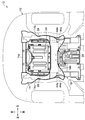
- FIG. 2 is a bottom view of the vehicle body front part including an engine undercover constituting the vehicle body front part structure of FIG.
- FIG. 3 is a plan view of the front portion of the vehicle body including the engine under cover as viewed from above.
- “upper” and “lower” indicate the upper side and the lower side along the vertical direction of the vehicle body
- “front” and “rear” indicate the front side and the rear side along the longitudinal direction of the vehicle body
- “Left” and “Right” indicate the left side and the right side along the vehicle width direction of the vehicle body.
- the vehicle body front structure 10 is fixed to attachment portions of left and right front side frames (not shown) extending along the front-rear direction of the vehicle body 12, and A subframe 14 provided on the lower side of the section, a floor frame 16 provided on the rear side of the subframe 14 and extending in the longitudinal direction of the vehicle body, and provided on the lower side of the subframe 14 and the floor frame 16. And an engine under cover 18 that mainly covers the lower side of an engine room in which an engine, a transmission, and the like (not shown) are provided.
- the front bulkhead provided at the front end portions of the left and right front side frames (not shown) is omitted.
- the sub frame 14 is formed of a substantially rectangular frame body made of a metal material, and includes a left side member 14a extending in the front-rear direction of the vehicle body, and a front-rear direction of the vehicle body.
- a right side member 14b extending toward the front, a columnar front cross member 14c spanning a front end of the left and right side members 14a and 14b in a substantially horizontal direction, and the left and right side members 14a,
- the rear cross member 14d spans the rear end portion of 14b along the substantially horizontal direction.
- a jack support portion 15 for jacking up the vehicle body 12 with a jack (not shown) is provided at a substantially central portion of the front cross member 14.
- a plurality of screw portions are provided at an intermediate portion of the front cross member 14c and front end portions of the left and right side members 14a and 14b, and a plurality of bolts 20 (four are exemplified in the present embodiment) fastened to the screw portions.
- the front end portion (protruding portion 32 described later) of the engine under cover 18 is fixed to the subframe 14 (see FIG. 2).
- the rear cross member 14d is provided with a plurality of screw portions, and the intermediate portion of the engine under cover 18 is connected to the middle portion of the engine under cover 18 via a plurality of bolts 20 (four in this embodiment are illustrated) fastened to the screw portions. It is fixed to the subframe 14 (see FIG. 2).
- a plurality of floor frames 16 formed of a metal material and extending along the longitudinal direction of the vehicle body are provided on the rear side of the subframe 14 (see FIG. 2).
- the front end portions of the plurality of floor frames 16 are provided with screw portions, and the rear end portions of the engine under cover 18 via a plurality of bolts 20 (four in this embodiment are illustrated) fastened to the screw portions. Is fixed to the floor frame 16. The point where the engine under cover 18 is fixed to the subframe 14 and the floor frame 16 will be described in detail later.
- FIG. 4 is a bottom view of the engine under cover
- FIG. 5 is a plan view of the engine under cover
- FIG. 6 is a plan view of a side frame mounted on the engine under cover shown in FIG. 5, and
- FIG. It is a perspective view of the engine under cover.
- the engine under cover 18 is provided so as to cover a lower side of an engine room in which an engine and a transmission (not shown) are arranged.
- the engine undercover 18 has a substantially rectangular shape in plan view and is formed of a resin material, and a resin provided on the front side of the engine undercover 18 and in a central portion along the vehicle width direction.
- a pair of metal reinforcing members 28 that are disposed in the left and right side portions and extend along the longitudinal direction of the vehicle body.
- the cover main body portion 22 includes a front cover portion 22a located between the front portion and the rear portion of the subframe 14, and a rear cover portion 22b located between the rear portion of the subframe 14 and the front end portion of the floor frame 16. Is done.
- a broken line portion 30 is provided along the vehicle width direction at a boundary portion between the front cover portion 22a and the rear cover portion 22b.
- the broken line portion 30 has a concave portion 30a having a substantially rectangular cross section between the front cover portion 22a and the rear cover portion 22b, and the central portion of the concave portion 30a has a V-shaped cross section.
- a groove 30b is formed.
- the front cover portion 22a or the rear cover portion 22b is provided so as to be bendable in an arc shape with the concave portion 30a and the groove portion 30b as fulcrums.
- the front cover portion 22a and the rear cover portion 22b are provided so as to be opened and closed independently.
- An elongated opening is formed at the center of the polygonal line 30 as shown in FIGS.
- the front end portion of the cover main body portion 22 (the front end portion of the front cover portion 22a) is provided with four projecting portions 32 projecting by a predetermined amount toward the front side, and the bolts 20 are inserted into the projecting portions 32.
- Bolt insertion holes 34a (see FIGS. 5 and 1) to be formed are formed (in this embodiment, four bolt insertion holes 34a are illustrated).
- Bolts 20 through which the respective bolt insertion holes 34a are inserted from the lower side to the upper side of the engine under cover 18 are formed at the intermediate portion of the front cross member 14c of the subframe 14 and the front end portions of the left and right side members 14a, 14b.
- the front end portion of the engine under cover 18 is fixed to the subframe 14 by fastening to a screw portion (not shown).
- a plurality of bolt insertion holes 34b through which the bolts 20 are inserted in an intermediate portion (the rear end portion of the front cover portion 22a and the front end portion of the rear cover portion 22b) along the vehicle body longitudinal direction of the cover main body portion 22. 5 and FIG. 1) (in this embodiment, four bolt insertion holes 34b are illustrated).
- Screws 20 formed at substantially the center and the left and right sides of the rear cross member 14d of the subframe 14 are bolts 20 inserted through the bolt insertion holes 34b from the lower side to the upper side of the engine under cover 18. Is fastened to the intermediate portion of the engine under cover 18 to be fixed to the subframe 14.
- a plurality of bolt insertion holes 34c through which the bolts 20 are inserted in a rear end portion (rear end portion of the rear cover portion 22b) along the vehicle body longitudinal direction of the cover main body portion 22. Is formed (in this embodiment, four bolt insertion holes 34c are illustrated).
- Bolts 20 that are inserted through the respective bolt insertion holes 34c from the lower side to the upper side of the engine under cover 18 are formed at the front end portion of the floor frame 16 that extends substantially in parallel along the longitudinal direction of the vehicle body (not shown). By fastening to the threaded portion, the rear end portion of the engine under cover 18 is fixed to the floor frame 16.
- the front cover portion 22a of the engine undercover 18 is fixed between the front portion (front end portion) and the rear portion (rear end portion) of the subframe 14, and the rear cover portion 22b of the engine undercover 18 It is fixed between the rear portion (rear end portion) of the frame 14 and the front end portion of the floor frame 16.
- the maintenance lid 24 is made of a resin material, and is configured by a substantially rectangular flat lid that closes a substantially rectangular opening 36 (see FIGS. 1 and 5) formed in the cover main body 22. After the maintenance lid 24 is slid to one side in the longitudinal direction of the vehicle body, the pair of fulcrum portions 24a (see FIG. 5) locked to the cover main body portion 22 side is rotated by a predetermined angle. For example, an engine oil exchange operation (not shown) can be performed through the opening 36.
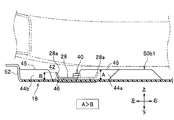
- FIG. 8 is a partially enlarged perspective view of a metal reinforcing member
- FIG. 9 is a longitudinal sectional view taken along line IX-IX in FIG. 8
- FIG. 10 is a longitudinal sectional view taken along line XX in FIG. It is.
- a pair of metal reinforcing members 28 extending along the longitudinal direction of the vehicle body are provided on the upper surface of the engine under cover 18 and on the left and right side portions along the vehicle width direction adjacent to the maintenance lid 24. 28 is provided. Since the pair of reinforcing members 28 and 28 have the same shape, the reinforcing member 28 provided on the left side of the engine under cover 18 will be described in detail, and the description of the reinforcing member 28 provided on the right side will be omitted.
- the reinforcing member 28 has a substantially U-shaped longitudinal section in which both side edges 28a in the axial direction are bent substantially upward, and is made of a metal that is long along the longitudinal direction of the vehicle body. It consists of members. One end portion along the axial direction of the reinforcing member 28 extends to the vicinity of the front end portion of the front cover portion 22a, and the other end portion along the axial direction of the reinforcing member 28 is the rear end of the front cover portion 22a. It is provided so as to extend to the vicinity of the portion (the broken line portion 30).
- the resin engine undercover 18 is formed with a ridge 38 (see FIG. 2) extending linearly along the longitudinal direction of the vehicle body and protruding upward by a predetermined length.
- the reinforcing member 28 is fixed via the rivet 40.
- the metal reinforcing member 28 comes into contact only with the ridge portion 38 and is easily fixed by the rivet 40, and the engine undercover is interposed via the rivet 40.
- the reinforcing member 28 made of a material different from that of 18 can be stably fixed.
- the reinforcing member 28 can be simply fixed to the engine under cover 18 by welding the shaft portion 40a (see FIG. 8) of the rivet 40 exposed to the outside from the upper surface of the reinforcing member 28 using welding means (not shown). Can do.
- the metal reinforcing member 28 fixed to the upper surface of the engine under cover 18 includes a metal subframe 14 disposed on the upper side of the engine under cover 18 and a part thereof overlapping. (Overlapping). Therefore, an interference region 42 between the metal members between the metal reinforcement member 28 fixed to the upper surface of the engine under cover 18 and the metal subframe 14 disposed above the reinforcement member 28. (See FIG. 6).
- first rib 44 a and the second rib 44 b are adjacent to the other end portion along the axial direction of the metal reinforcing member 28 and between the other end portion and the broken line portion 30.
- the first rib 44a and the second rib 44b are integrally formed of the same resin material as that of the engine under cover 18, and are arranged in a state of being spaced apart from each other along the vehicle width direction.
- the first rib 44a and the second rib 44b are formed so that the upper end 45 protrudes upward, and the dimension A in the height direction of the upper end 45 is the side of the metal reinforcing member 28. It is set higher than the height dimension B of the edge portion 28a (dimension A> dimension B; see FIG. 10).
- the first rib 44a and / or the second rib 44b made of resin function as an obstacle between the metal reinforcing member 28 and the metal subframe 14, and contact (interference) between the metal members. ) Can be preferably avoided.
- a notch 46 is formed by notching a wall between the first rib 44a and the second rib 44b. Provided (see FIG. 7). By providing the notch 46, for example, water drainage in the longitudinal direction of the vehicle body can be improved.
- the water adjacent to the notch 46 and between the other end of the reinforcing member 28 and the first rib 44 a is formed in a substantially elliptical shape in plan view.
- a punching hole 48 is formed through both the upper and lower surfaces (see FIG. 7).
- the engine under cover 18 and the maintenance lid 24 are provided with a plurality of beads 50a to 50d that are convex upward and extend in the longitudinal direction of the vehicle body and have different lengths (see FIG. 7). ). By providing the plurality of beads 50a to 50d, desired rigidity of the resin engine undercover 18 and the maintenance lid 24 can be ensured.
- a pair of relatively long beads 50a extending substantially parallel to the axis of the reinforcing member 28 are provided in the vicinity of the side end portion along the vehicle width direction of the front cover portion 22a.
- a plurality of relatively short beads 50b that are arranged substantially in parallel along the vehicle width direction are provided in the vicinity of the rear end portion (the broken line portion 30) of the cover portion 22a.
- the bead 50b1 that is closest to the left and right end portions along the vehicle width direction of the engine undercover 18 is formed continuously with the first rib 44a (see FIG. 7), and the interference region 42
- the strength of the engine undercover 18 can be further enhanced by the cooperative action of the bead 50b1 belonging to the above and the rib 44a.
- the second rib 44b is formed by raising the side edge portion 52 (see FIG. 10) of the engine under cover 18 upward.
- the rear cover portion 22b is provided with a pair of beads 50c formed with a relatively large width dimension along the vehicle width direction. Furthermore, in order to ensure the rigidity of the maintenance lid 24 made of a resin material, a plurality of beads 50d extending along the longitudinal direction of the vehicle body are provided.
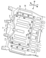
- FIG. 11 is an enlarged perspective view of a part of the engine under cover including the maintenance lid as viewed from above
- FIG. 12 is an enlarged perspective view of a portion of the engine under cover including the maintenance lid as viewed from below
- FIG. FIG. 14A is a partially enlarged perspective view showing a maintenance lid support mechanism
- FIG. 14A is a partially enlarged perspective view for explaining a maintenance lid removing operation
- FIG. 14B is a cross-sectional view of FIG.
- FIG. 15A is a partially enlarged perspective view for explaining the operation of removing the maintenance lid
- FIG. 15B is along the BB line in FIG. 15A
- 16A is a partially enlarged perspective view for explaining the operation of removing the maintenance lid
- FIG. 16B is a vertical end view taken along the line CC of FIG. 16A.
- Fig. 17 (a) shows the rear edge of the maintenance lid from below.
- 17 (b) to 17 (d) are explanatory views of the operation of the trailing edge claw
- FIGS. 18 (a) to 18 (c) are longitudinal sectional views for explaining the operation of removing the maintenance lid.
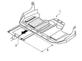
- FIG. 19 is an explanatory diagram showing a state where a part of the engine under cover is removed during maintenance.
- a plurality of lid bolt fastening portions 100 are provided on the peripheral portion of the maintenance lid 24, and the maintenance lid is formed by the plurality of lid bolt fastening portions 100.
- 24 is fixed to the cover main body 22 (front cover 22a).
- Each lid bolt fastening portion 100 includes a nut 100b (clip with nut) inserted into the upper surface side of the cover main body portion 22, and a lid bolt 100a fastened to the nut 100b from the lower side of the cover main body portion 22 (see FIG. 12). It consists of.
- the maintenance lid 24 is slidable by loosening the lid bolt 100a and releasing it from the nut 100b.
- the maintenance lid 24 includes a rotation support mechanism 102 that supports the front edge 24a of the maintenance lid 24 in a cantilevered manner so as to be rotatable at a predetermined angle when the maintenance lid 24 is slid and removed as will be described later.
- the rotation support mechanism 102 includes a pair of side rotation support portions 104 and 104 provided on the left and right sides of the front edge portion 24a of the maintenance lid 24, and the side rotation between the pair of side rotation support portions 104 and 104. And a central rotation support portion 106 provided on the rear side of the support portions 104 and 104.
- the rotation support mechanism 102 has a pair of L-shaped claw portions 108 and 108 provided on the cover main body 22 side at positions corresponding to the left and right sides of the front edge portion 24a of the maintenance lid 24, and the side rotation.
- the pair of side rotation support portions 104 is provided between the opening 110 formed in the front edge portion 24a of the maintenance lid 24 and the front edge portion 24a, and is a cross section provided on the cover body portion 22 side. A portion that is cantilevered by the L-shaped claw portion 108.
- the center rotation support portion 106 is formed by a belt-like body that protrudes from the center portion of the arc portion curved along the side wall portion 112 of the semi bowl-shaped projection portion 17 toward the front side by a predetermined length (FIG. 16A). Reference), the leading end portion of the belt-like body is bent upward by a predetermined angle to form a locking portion 118. Accordingly, the central rotation support portion 106 has a fixed portion 106a fixed to the maintenance lid 24 side, an intermediate portion 106b projecting from the arc portion toward the front side, and a semi bowl-like shape extending upward from the intermediate portion 106b. It is comprised from the latching
- the semi bowl-shaped protrusion 17 includes a top portion 17a formed of a flat surface, a side wall portion 112 having a curved surface formed by being curved along the circumferential direction, and a rear portion at the center of the side wall portion 112. It has a box portion 120 that protrudes by a predetermined length and in which an opening 114 is formed. By providing the opening 114 of the box portion 120, the insertion of the nut (clip with nut) 100b of the lid bolt fastening portion can be facilitated.
- the semi bowl-shaped protrusion 17 projects from the box part 120 toward the rear side and covers the upper surface part of the fixing part 106a of the central rotation support part 106, and is fixed to the upper surface of the covering part 122.
- Frame portion 124
- a pair of locking ribs 126 formed in a substantially triangular shape when viewed from the side are provided on the left and right sides of the opening 114 formed in the box portion 120 constituting the side wall portion 112.
- the pair of locking ribs 126 are provided so as to connect the box portion 120 around the opening 114 and the upper surface of the covering portion 122, and the locking portion 118 of the central rotation support portion 106 is the side wall portion 112. The locking strength when locked to the inner wall surface 116 at the periphery of the opening 114 can be increased.
- a pair of stopper portions 128 are provided on the upper surface of the cover main body portion 22. As shown in FIG. 14A, the stopper portion 128 locks the front edge portion 24 a of the maintenance lid 24 when the maintenance lid 24 is slid forward, and the maintenance lid 24 slides. On the other hand, as shown in FIGS. 15 (a) and 16 (a), when the maintenance lid 24 is slid to the rear side as shown in FIG. Therefore, the locked state is released, and the maintenance lid 24 can be rotated.
- the rear edge 24b of the maintenance lid 24 is provided with a pair of rear edge claws 130 formed so as to protrude in a substantially L-shaped cross section toward the rear side, as shown in FIG.
- Each trailing edge claw 130 is provided so as to pass through a rectangular opening 132 formed in the maintenance lid 24 along the lower surface from the upper surface of the maintenance lid 24, and bends substantially parallel to the lower surface of the maintenance lid 24.
- the maintenance lid 24 is locked by the portion 130a.
- the dimension along the front-rear direction of the rectangular opening 132 is set to be larger than the dimension along the front-rear direction of the trailing edge claw 130, and the trailing edge claw 130 is slidable within the rectangular opening 132. (See FIGS. 17B to 17D).
- the vehicle body front structure 10 according to the present embodiment is basically configured as described above. Next, the function and effect will be described.
- the lid bolt 100a is loosened from the lower side of the cover main body portion 22 and separated from the nut 100b.
- the maintenance lid 24 is slidable.
- the pair of side rotation support portions 104 are respectively locked to the claw portions 108 having an L-shaped cross section.
- the center rotation support portion 106 is separated from the inner wall surface 116 around the opening 114 of the side wall portion 112 and is in a free state.
- the front edge portion 24 a of the maintenance lid 24 is in a state of being locked by the stopper portion 128.
- the rear edge 24 b of the maintenance lid 24 is in a state of being locked by the rear edge claw 130 that penetrates the rectangular opening 132.
- the maintenance lid 24 is slid by a predetermined length toward the rear side (in the direction of the arrow in FIG. 15B).
- the central rotation support portion 106 abuts against the inner wall surface 116 at the periphery of the opening 114 of the side wall portion 112 and the sliding operation is locked.
- the claw portion 108 having an L-shaped cross section comes into contact with the peripheral edge of the opening 110 on the front edge portion 24a side, and the sliding operation is locked.
- the front edge portion 24a of the maintenance lid 24 is separated from the stopper portion 128 and the locked state is released.
- the rear edge claw 130 provided on the cover main body 22 side is detached from the lower surface of the rear edge 24b of the maintenance lid 24 and becomes free in the rectangular opening 132, and is locked by the rear edge claw 130. Is released.
- the front edge portion It is rotated by a predetermined angle in the counterclockwise direction (arrow direction in FIG. 16B) with 24a as a fulcrum.
- the locking portion 118 of the center rotation support portion 106 is separated from the inner wall surface 116 at the periphery of the opening 114 of the side wall portion 112 and the center.
- the locking part 118 of the rotation support part 106 is in a free state.
- the engaging portion 118 of the central rotation support portion 106 is kept engaged with the inner wall surface 116 around the opening 114 of the side wall portion 112 until the initial stage of the rotation operation of the maintenance lid 24.
- the operator's force for removing the maintenance lid 24 may be applied to the maintenance lid 24. Since the bent locking portion 118 presses the inner wall surface 116 at the periphery of the opening 114 of the side wall portion 112 (see FIG. 16B), the load applied to the side rotation support portion 104 is reduced. Can do.
- the pair of side rotation support portions 104 locked to the cover main body portion 22 side is rotated by a predetermined angle.
- an engine oil change operation (not shown) can be performed through the opening 36.
- the sliding operation of the maintenance lid 24 is performed by the side rotation support portion 104 and the center rotation support portion 106.
- the maintenance lid 24 is rotated about the side rotation support portion 104 as a fulcrum. Accordingly, the number of supporting points can be increased when the operator applies a high load, compared to the rotation operation of the maintenance lid 24 to which a low load is applied only by the gravity of the maintenance lid 24. 24 can be made thin to reduce the weight.
- the lightweight maintenance lid 24 is slid and then rotated, so that the maintenance lid 24 can be suspended from the cover body portion 22 by its gravity action. Maintenance work can be performed without removing the entire maintenance lid 24 from the portion 22. Furthermore, in the present embodiment, a space for pulling out the maintenance lid 24 as in the prior art is not necessary, so that the work space is not enlarged and the maintainability can be further improved.
- a rear edge claw 130 is provided on the cover main body 22 side, and the rear edge claw 130 is provided so as to be able to lock a rectangular opening 132 formed in the rear edge 24b of the maintenance lid 24. It is done. Therefore, the front edge portion 24a of the maintenance lid 24 is provided so that the side rotation support portion 104 is locked by the claw portion 108 having a substantially L-shaped cross section and is placed on the upper surface of the cover body portion 22, and the maintenance lid. Since the rear edge 24b of the cover 24 is locked by the rear edge claw 130 on the cover main body 22 side, the fastening operation of fastening the maintenance cover 24 to the cover main body 22 in a state where the maintenance cover 24 is prevented from falling is easy. Can be done.
- the front part of the engine under cover 18 has a semi bowl-like protrusion 17 that avoids interference with the jack support 15, and the locking part 118 of the central rotation support 106 is locked.
- the side wall portion 112 is provided on the semi bowl-like projection 17 so that the side wall portion 112 becomes a curved surface and has high strength, and the locking strength for locking the locking portion 118 can be increased. it can.
- FIG. 20 is an explanatory view showing a state in which air flows through the lower surface of the engine undercover.
- the left and right side portions along the vehicle width direction adjacent to the maintenance lid 24 are provided.
- a pair of metal reinforcing members 28, 28 extending along the longitudinal direction of the vehicle body is disposed.
- the desired rigidity and strength of the engine undercover 18 is ensured by the pair of metal reinforcing members 28, 28, and the engine undercover 18 is deformed by a negative pressure on the lower side during high-speed traveling. Can be greatly contributed to aerodynamic performance.
- the bead 50b1 that is closest to the left and right side edges 52 along the vehicle width direction of the engine undercover 18 is formed continuously with the first rib 44a.
- a notch 46 is formed between the first rib 44a and the second rib 44b that are spaced apart from each other by a predetermined distance along the vehicle width direction.
- the notch 46 can improve the water drainage in the longitudinal direction of the vehicle body, for example.
- drain hole 48 adjacent to the notch 46, draining to the outside through the drain hole 48 is facilitated.
- 30 and the front cover portion 22a and the rear cover portion 22b are provided so as to be able to be opened and closed independently with the broken line portion 30 as a fulcrum.
- the front cover portion 22a is set at a predetermined angle with the broken line portion 30 as a fulcrum.
- maintenance work on the engine side such as an engine or transmission (not shown) can be performed easily and quickly.
- the rear cover portion 22b is inclined at a predetermined angle with the broken line portion 30 as a fulcrum, maintenance work for an exhaust system element (not shown) can be performed easily and quickly.
Landscapes
- Engineering & Computer Science (AREA)
- Chemical & Material Sciences (AREA)
- Combustion & Propulsion (AREA)
- Transportation (AREA)
- Mechanical Engineering (AREA)
- Body Structure For Vehicles (AREA)
Abstract
Description
本発明の他の目的は、樹脂製のエンジンアンダカバーにメンテナンス蓋を設けた場合であっても、エンジンアンダカバーに所定の剛性・強度を確保することが可能な車体前部構造を提供することにある。
また、本発明では、樹脂製のエンジンアンダカバーにメンテナンス蓋を設けた場合であっても、エンジンアンダカバーに所定の剛性・強度を確保することが可能な車体前部構造を得ることができる。
12 車体
14 サブフレーム
16 フロアフレーム
17 半お椀状突起部
18 エンジンアンダカバー
22 カバー本体部
22a 前方カバー部
22b 後方カバー部
24 メンテナンス蓋
24a 前縁部
24b 後縁部
28 補強部材
30 折れ線部
42 干渉領域
44a、44b リブ
46 切り欠き部
48 水抜き孔
50a~50d ビード
52 側縁部
104 側方回転支持部
106 中央回転支持部
108 爪部
110 開口部
112 側壁部(側壁)
114 開口
116 内壁面(壁面)
118 係止部
126 係止用リブ
130 後縁爪
132 矩形状開口部
Claims (11)
- 車体前部の下側を覆うエンジンアンダカバーが設けられる車体前部構造において、
前記エンジンアンダカバーの中央部には、メンテナンス蓋が設けられ、
前記メンテナンス蓋は、前記メンテナンス蓋の前縁部の左右側に設けられる一対の側方回転支持部と、前記一対の側方回転支持部間で前記側方回転支持部よりも後側に設けられる中央回転支持部とを備え、
前記側方回転支持部は、前記エンジンアンダカバーに設けられる断面L字状の爪部に係止可能な開口部を有し、
前記中央回転支持部は、前記エンジンアンダカバーに設けられる側壁の壁面に係止可能な係止部を有し、
前記メンテナンス蓋を後側にスライドさせた際、前記側方回転支持部と前記中央回転支持部とによって前記メンテナンス蓋のスライド動作を係止し、前記一対の側方回転支持部を支点として前記メンテナンス蓋が回転動作されることを特徴とする車体前部構造。 - 前記エンジンアンダカバーには、後縁爪が設けられ、前記後縁爪は、前記メンテナンス蓋に形成される矩形状開口部に係止されることを特徴とする請求の範囲第1項に記載の車体前部構造。
- 前記エンジンアンダカバーは、前縁部にジャッキ支持部との干渉を回避する半お椀状突起部を有し、前記中央回転支持部の係止部が係止される側壁は、前記半お椀状突起部に設けられることを特徴とする請求の範囲第1項に記載の車体前部構造。
- 前記側壁の開口の周縁部には、係止用リブが設けられることを特徴とする請求の範囲第3項に記載の車体前部構造。
- 前記中央回転支持部の係止部は、前記メンテナンス蓋の回転動作の初期まで前記側壁の壁面と係合していることを特徴とする請求の範囲第1項に記載の車体前部構造。
- 前記エンジンアンダカバーは、サブフレームの前部及び後部間の前方カバー部と、前記サブフレーム及びフロアフレーム間の後方カバー部とを含み、前記前方カバー部と前記後方カバー部との境界に形成された折れ線部を介して、前記前方カバー部と前記後方カバー部とが独立に開閉可能に設けられることを特徴とする請求の範囲第1項に記載の車体前部構造。
- 前記エンジンアンダカバーは、樹脂製であり車体前後方向でサブフレームの前部及び後部にそれぞれ固定され、
前記メンテナンス蓋に隣接し車幅方向に沿った側方部位には、金属製の補強部材が車体前後方向に延設されることを特徴とする請求の範囲第1項に記載の車両前部構造。 - 前記エンジンアンダカバーには、前記金属製の補強部材の上側に配置される金属製のサブフレームとの干渉領域にリブが立設されることを特徴とする請求の範囲第7項に記載の車両前部構造。
- 前記エンジンアンダカバーは、車体前後方向に延在するビードを有し、前記ビードに連続して第1リブを立設することを特徴とする請求の範囲第8項に記載の車両前部構造。
- 前記エンジンアンダカバーは、前記エンジンアンダカバーの側縁部を立ち上げて第2リブを形成し、前記ビードに連続した前記第1リブとの間に切り欠き部が設けられることを特徴とする請求の範囲第9項に記載の車両前部構造。
- 前記エンジンアンダカバーには、前記切り欠き部に隣接して水抜き孔が形成されることを特徴とする請求の範囲第10項に記載の車両前部構造。
Priority Applications (4)
| Application Number | Priority Date | Filing Date | Title |
|---|---|---|---|
| US13/876,593 US8746782B2 (en) | 2010-09-30 | 2011-09-16 | Car body forepart structure |
| CN201180047582.3A CN103153761B (zh) | 2010-09-30 | 2011-09-16 | 车身前部构造 |
| JP2012536346A JP5584772B2 (ja) | 2010-09-30 | 2011-09-16 | 車体前部構造 |
| EP11828828.1A EP2623401B1 (en) | 2010-09-30 | 2011-09-16 | Car body forepart structure |
Applications Claiming Priority (4)
| Application Number | Priority Date | Filing Date | Title |
|---|---|---|---|
| JP2010-220959 | 2010-09-30 | ||
| JP2010220959 | 2010-09-30 | ||
| JP2010220958 | 2010-09-30 | ||
| JP2010-220958 | 2010-09-30 |
Publications (1)
| Publication Number | Publication Date |
|---|---|
| WO2012043268A1 true WO2012043268A1 (ja) | 2012-04-05 |
Family
ID=45892735
Family Applications (1)
| Application Number | Title | Priority Date | Filing Date |
|---|---|---|---|
| PCT/JP2011/071184 Ceased WO2012043268A1 (ja) | 2010-09-30 | 2011-09-16 | 車体前部構造 |
Country Status (5)
| Country | Link |
|---|---|
| US (1) | US8746782B2 (ja) |
| EP (1) | EP2623401B1 (ja) |
| JP (1) | JP5584772B2 (ja) |
| CN (1) | CN103153761B (ja) |
| WO (1) | WO2012043268A1 (ja) |
Cited By (10)
| Publication number | Priority date | Publication date | Assignee | Title |
|---|---|---|---|---|
| WO2015098538A1 (ja) * | 2013-12-25 | 2015-07-02 | トヨタ自動車株式会社 | 異種材料の接合構造 |
| JP2015123790A (ja) * | 2013-12-25 | 2015-07-06 | 三菱自動車工業株式会社 | 車両のアンダーカバー構造 |
| KR101534735B1 (ko) * | 2013-12-30 | 2015-07-07 | 현대자동차 주식회사 | 차체 하부 차폐 구조 |
| JP2018065461A (ja) * | 2016-10-19 | 2018-04-26 | トヨタ自動車株式会社 | サスペンションメンバ |
| CN108495778A (zh) * | 2016-01-27 | 2018-09-04 | 欧拓管理公司 | 具有安装点的车身底部面板 |
| CN109421821A (zh) * | 2017-08-25 | 2019-03-05 | 丰田自动车工程及制造北美公司 | 包括底盖加强构件的底盖组件 |
| JP2019142416A (ja) * | 2018-02-22 | 2019-08-29 | トヨタ自動車株式会社 | 車両下部構造 |
| JP2022074380A (ja) * | 2020-11-04 | 2022-05-18 | 日産自動車株式会社 | アンダーカバー構造 |
| JP2022134468A (ja) * | 2021-03-03 | 2022-09-15 | フタバ産業株式会社 | 車両用アンダーカバー及び車両用アンダーカバーの製造方法 |
| JP2024064208A (ja) * | 2022-10-27 | 2024-05-14 | 株式会社イノアックコーポレーション | 車両用アンダーカバー |
Families Citing this family (44)
| Publication number | Priority date | Publication date | Assignee | Title |
|---|---|---|---|---|
| US8875834B1 (en) * | 2013-04-12 | 2014-11-04 | GM Global Technology Operations LLC | Increased stiffness underbody panel |
| FR3009822B1 (fr) * | 2013-08-20 | 2016-10-21 | Peugeot Citroen Automobiles Sa | Ecrans destines a etre fixes sous la caisse d'un vehicule automobile pour assurer une fonction aerodynamique et/ou acoustique |
| JP5971234B2 (ja) * | 2013-12-25 | 2016-08-17 | トヨタ自動車株式会社 | 樹脂パネル構造 |
| DE202014001822U1 (de) * | 2014-02-26 | 2015-05-28 | GM Global Technology Operations LLC (n. d. Gesetzen des Staates Delaware) | Vorrichtung zur Befestigung einer Unterbodenverkleidung an einem Kraftfahrzeug |
| KR101563883B1 (ko) * | 2014-05-22 | 2015-10-29 | 한화첨단소재 주식회사 | 스티프너가 일체화 된 자동차용 언더커버 |
| JP6401969B2 (ja) * | 2014-08-20 | 2018-10-10 | 日本プラスト株式会社 | 車両用アンダーカバー |
| DE102014112090A1 (de) | 2014-08-25 | 2016-02-25 | Benteler Automobiltechnik Gmbh | Achsträger für ein Kraftfahrzeug sowie Verfahren zur Herstellung eines Achsträgers |
| JP6092830B2 (ja) * | 2014-10-09 | 2017-03-08 | 本田技研工業株式会社 | 車体底部構造 |
| JP6488826B2 (ja) * | 2015-03-31 | 2019-03-27 | 株式会社デンソー | 外乱防止カバー |
| US20210053522A1 (en) * | 2015-08-14 | 2021-02-25 | Scrape Armor, Inc. | Vehicle protection adapter |
| AU2016308464B2 (en) | 2015-08-14 | 2020-11-19 | Scrape Armour, Inc. | Vehicle protection apparatus |
| US20220396228A1 (en) * | 2021-06-10 | 2022-12-15 | Scrape Armor, Inc. | Vehicle protection apparatus |
| US12441260B2 (en) * | 2015-08-14 | 2025-10-14 | Scrape Armor, Inc. | Vehicle protection apparatus |
| FR3053395B1 (fr) * | 2016-06-30 | 2018-08-10 | Continental Automotive France | Procede et systeme de detection d'absence de protection sous moteur |
| CN106240656A (zh) * | 2016-08-05 | 2016-12-21 | 江苏友孚汽车部件科技有限公司 | 一种具有良好排水、散热功能的一体化汽车导流装置 |
| CN106240655A (zh) * | 2016-08-05 | 2016-12-21 | 江苏友孚汽车部件科技有限公司 | 一种可升降的汽车一体化导流板装置 |
| DE102016115753B8 (de) | 2016-08-25 | 2023-06-22 | Dr. Ing. H.C. F. Porsche Aktiengesellschaft | Klappbare Unterbodenverkleidung |
| US20180215328A1 (en) * | 2017-01-31 | 2018-08-02 | Ford Global Technologies, Llc | Twin sheet belly pan and method of production |
| MX2019014766A (es) * | 2017-06-12 | 2020-02-07 | Unipres Corp | Estructura para acoplar una cubierta inferior a la carroceria del vehiculo. |
| US10189516B1 (en) * | 2017-07-12 | 2019-01-29 | Ford Global Technologies, Llc | Vehicle aerodynamic assemblies for providing passive water management |
| DE102017215587A1 (de) * | 2017-09-05 | 2019-03-07 | Röchling Automotive SE & Co. KG | Befestigungskörper zur Befestigung einer Unterbodenverkleidung an einem Kraftfahrzeug-Unterboden |
| JP6946997B2 (ja) * | 2017-12-13 | 2021-10-13 | トヨタ自動車株式会社 | 車両用のオイルパンガード |
| FR3076807B1 (fr) * | 2018-01-12 | 2024-08-23 | Psa Automobiles Sa | Ecran aeraulique pour plate-forme de vehicule automobile avec evidement d’acces en son interieur |
| FR3084872B1 (fr) * | 2018-08-07 | 2022-06-24 | Psa Automobiles Sa | Assemblage simplifie d’un panneau de protection sous-moteur sur vehicule automobile |
| DE102018213938A1 (de) * | 2018-08-17 | 2020-02-20 | Röchling Automotive SE & Co. KG | Flächiges Kraftfahrzeug-Verkleidungsbauteil mit integriertem aufdoppelndem Verstärkungsabschnitt |
| JP6734337B2 (ja) * | 2018-09-27 | 2020-08-05 | 本田技研工業株式会社 | 車体前部構造 |
| FR3087180B1 (fr) * | 2018-10-16 | 2020-10-23 | Psa Automobiles Sa | Sous ensemble de carrosserie pour un chassis de vehicule automobile, comprenant un parechoc et un carenage de fond assembles sur un panneau transversal |
| FR3087740B1 (fr) * | 2018-10-24 | 2021-05-07 | Psa Automobiles Sa | Vehicule automobile avec deflecteur sous-plancher a deux niveaux |
| FR3099743B1 (fr) * | 2019-08-07 | 2021-07-16 | Psa Automobiles Sa | Déflecteur à pattes de couplage, pour un soubassement de véhicule |
| FR3099740A1 (fr) * | 2019-08-09 | 2021-02-12 | Psa Automobiles Sa | Deflecteur aerodynamique sous plancher avec dispositif de pre-maintien |
| US20210129781A1 (en) * | 2019-11-05 | 2021-05-06 | Scrape Armor, Inc. | Vehicle protection adapter |
| US11541945B2 (en) | 2019-11-27 | 2023-01-03 | Ameri-Kart | Vehicle underbelly structure |
| US11953084B2 (en) * | 2020-06-09 | 2024-04-09 | Nissan Motor Co., Ltd. | Structure for protecting drive device |
| US11891121B2 (en) * | 2021-07-13 | 2024-02-06 | Honda Motor Co., Ltd. | Wheel casing |
| JP7361145B2 (ja) * | 2022-02-16 | 2023-10-13 | 本田技研工業株式会社 | 車両下部構造 |
| EP4299420A1 (de) * | 2022-07-01 | 2024-01-03 | Autotech Engineering S.L. | Hilfsrahmen für ein fahrzeug, insbesondere elektrofahrzeug |
| KR20240006907A (ko) * | 2022-07-07 | 2024-01-16 | 현대자동차주식회사 | 차량용 언더커버구조 |
| EP4328118A1 (en) | 2022-08-25 | 2024-02-28 | FERRARI S.p.A. | Car provided with an internal combustion engine |
| IT202200018468A1 (it) * | 2022-09-12 | 2024-03-12 | Ferrari Spa | Automobile |
| US12084111B2 (en) * | 2022-09-12 | 2024-09-10 | Ferrari S.P.A. | Motor vehicle provided with a reinforcing structure |
| CN115892245B (zh) * | 2022-11-29 | 2025-04-15 | 东风商用车有限公司 | 一种车身地板结构及车辆 |
| DE102023201659B4 (de) * | 2023-02-23 | 2024-12-12 | Audi Aktiengesellschaft | Kraftfahrzeug sowie Verfahren zum Herstellen eines Kraftfahrzeugs |
| FR3148209A1 (fr) * | 2023-04-27 | 2024-11-01 | Psa Automobiles Sa | Déflecteur de soubassement pour véhicule automobile. |
| CN119099734A (zh) * | 2023-06-07 | 2024-12-10 | 本田技研工业株式会社 | 车辆底部结构 |
Citations (6)
| Publication number | Priority date | Publication date | Assignee | Title |
|---|---|---|---|---|
| JPH0413390U (ja) * | 1990-05-24 | 1992-02-03 | ||
| JPH0462291U (ja) * | 1990-10-11 | 1992-05-28 | ||
| JP2000177652A (ja) | 1998-12-15 | 2000-06-27 | Fuji Heavy Ind Ltd | アンダーカバー点検孔構造 |
| JP2000190873A (ja) * | 1998-12-25 | 2000-07-11 | Nissan Motor Co Ltd | 自動車のアンダ―カバ―構造 |
| JP2006111249A (ja) * | 2004-09-14 | 2006-04-27 | Toyota Motor Corp | エンジンアンダカバー取付構造 |
| JP2010137832A (ja) | 2008-12-15 | 2010-06-24 | Honda Motor Co Ltd | 車体構造 |
Family Cites Families (16)
| Publication number | Priority date | Publication date | Assignee | Title |
|---|---|---|---|---|
| JPS5780373U (ja) * | 1980-11-04 | 1982-05-18 | ||
| JPS5976483U (ja) * | 1982-11-15 | 1984-05-24 | 本田技研工業株式会社 | エンジンル−ムのアンダ−カバ− |
| JPH04133990U (ja) * | 1991-06-05 | 1992-12-14 | マツダ株式会社 | 車両のアンダカバー取付構造 |
| GB2362360B (en) * | 1997-07-14 | 2002-01-09 | Land Rover Group Ltd | Motor vehicle undertray assemblies |
| JP4076487B2 (ja) * | 2003-09-25 | 2008-04-16 | トヨタ自動車株式会社 | 車両用フード構造 |
| DE10345328A1 (de) * | 2003-09-30 | 2005-05-19 | Dr.Ing.H.C. F. Porsche Ag | Aerodynamisch ausgebildetes Verkleidungsteil für die Unterseite eines Kraftfahrzeuges, insbesondere Personenwagens |
| DE102004035435A1 (de) * | 2004-07-21 | 2006-03-16 | GM Global Technology Operations, Inc., Detroit | Verstärkungselement für einen unteren Bereich eines Frontstoßfängers, sowie damit augerüsteter Frontstoßfänger für ein Kraftfahrzeug |
| JP2008030524A (ja) * | 2006-07-26 | 2008-02-14 | Mazda Motor Corp | アンダーカバー構造 |
| EP1972527B1 (fr) | 2007-03-21 | 2012-01-11 | Peugeot Citroën Automobiles S.A. | Carénage de protection moteur renforcé pour véhicule |
| JP4602389B2 (ja) * | 2007-10-19 | 2010-12-22 | 本田技研工業株式会社 | 車両用アンダーカバー |
| DE112008004003B8 (de) * | 2008-10-31 | 2014-11-06 | Toyota Jidosha Kabushiki Kaisha | Fahrzeug-Bodenabdeckung |
| DE102008058993B4 (de) | 2008-11-25 | 2020-11-19 | Röchling Automotive AG & Co. KG | Kraftfahrzeug mit einem Strömungsleitmechanismus |
| JP4787899B2 (ja) * | 2008-11-26 | 2011-10-05 | 本田技研工業株式会社 | エンジンルームカバー及びエンジンルームカバーの組み付け方法 |
| JP5354351B2 (ja) * | 2009-03-05 | 2013-11-27 | スズキ株式会社 | 車体後部のリヤフロア構造 |
| DE202009017309U1 (de) | 2009-12-18 | 2010-03-25 | Peguform Gmbh | Unterbodenverkleidung |
| FR2975659B1 (fr) * | 2011-05-25 | 2013-11-22 | Peugeot Citroen Automobiles Sa | Cache sous caisse pour un vehicule automobile, muni de moyens de fixation magnetique. |
-
2011
- 2011-09-16 CN CN201180047582.3A patent/CN103153761B/zh not_active Expired - Fee Related
- 2011-09-16 JP JP2012536346A patent/JP5584772B2/ja not_active Expired - Fee Related
- 2011-09-16 US US13/876,593 patent/US8746782B2/en active Active
- 2011-09-16 WO PCT/JP2011/071184 patent/WO2012043268A1/ja not_active Ceased
- 2011-09-16 EP EP11828828.1A patent/EP2623401B1/en not_active Not-in-force
Patent Citations (6)
| Publication number | Priority date | Publication date | Assignee | Title |
|---|---|---|---|---|
| JPH0413390U (ja) * | 1990-05-24 | 1992-02-03 | ||
| JPH0462291U (ja) * | 1990-10-11 | 1992-05-28 | ||
| JP2000177652A (ja) | 1998-12-15 | 2000-06-27 | Fuji Heavy Ind Ltd | アンダーカバー点検孔構造 |
| JP2000190873A (ja) * | 1998-12-25 | 2000-07-11 | Nissan Motor Co Ltd | 自動車のアンダ―カバ―構造 |
| JP2006111249A (ja) * | 2004-09-14 | 2006-04-27 | Toyota Motor Corp | エンジンアンダカバー取付構造 |
| JP2010137832A (ja) | 2008-12-15 | 2010-06-24 | Honda Motor Co Ltd | 車体構造 |
Non-Patent Citations (1)
| Title |
|---|
| See also references of EP2623401A4 |
Cited By (20)
| Publication number | Priority date | Publication date | Assignee | Title |
|---|---|---|---|---|
| JP2015124797A (ja) * | 2013-12-25 | 2015-07-06 | トヨタ自動車株式会社 | 異種材料の接合構造 |
| JP2015123790A (ja) * | 2013-12-25 | 2015-07-06 | 三菱自動車工業株式会社 | 車両のアンダーカバー構造 |
| US9950748B2 (en) | 2013-12-25 | 2018-04-24 | Toyota Jidosha Kabushiki Kaisha | Heterogeneous material joint structure |
| WO2015098538A1 (ja) * | 2013-12-25 | 2015-07-02 | トヨタ自動車株式会社 | 異種材料の接合構造 |
| KR101534735B1 (ko) * | 2013-12-30 | 2015-07-07 | 현대자동차 주식회사 | 차체 하부 차폐 구조 |
| US20190009835A1 (en) * | 2016-01-27 | 2019-01-10 | Autoneum Management Ag | Underbody panel having mounting points |
| CN108495778A (zh) * | 2016-01-27 | 2018-09-04 | 欧拓管理公司 | 具有安装点的车身底部面板 |
| US10286960B2 (en) | 2016-10-19 | 2019-05-14 | Toyota Jidosha Kabushiki Kaisha | Suspension member |
| JP2018065461A (ja) * | 2016-10-19 | 2018-04-26 | トヨタ自動車株式会社 | サスペンションメンバ |
| CN109421821A (zh) * | 2017-08-25 | 2019-03-05 | 丰田自动车工程及制造北美公司 | 包括底盖加强构件的底盖组件 |
| JP2019069755A (ja) * | 2017-08-25 | 2019-05-09 | トヨタ モーター エンジニアリング アンド マニュファクチャリング ノース アメリカ,インコーポレイティド | アンダーカバー補強部材を含むアンダーカバー組立体 |
| JP2019142416A (ja) * | 2018-02-22 | 2019-08-29 | トヨタ自動車株式会社 | 車両下部構造 |
| JP6992585B2 (ja) | 2018-02-22 | 2022-01-13 | トヨタ自動車株式会社 | 車両下部構造 |
| JP2022074380A (ja) * | 2020-11-04 | 2022-05-18 | 日産自動車株式会社 | アンダーカバー構造 |
| JP2024101048A (ja) * | 2020-11-04 | 2024-07-26 | 日産自動車株式会社 | アンダーカバー構造 |
| JP7543851B2 (ja) | 2020-11-04 | 2024-09-03 | 日産自動車株式会社 | アンダーカバー構造 |
| JP7794234B2 (ja) | 2020-11-04 | 2026-01-06 | 日産自動車株式会社 | アンダーカバー構造 |
| JP2022134468A (ja) * | 2021-03-03 | 2022-09-15 | フタバ産業株式会社 | 車両用アンダーカバー及び車両用アンダーカバーの製造方法 |
| JP7538066B2 (ja) | 2021-03-03 | 2024-08-21 | フタバ産業株式会社 | 車両用アンダーカバー及び車両用アンダーカバーの製造方法 |
| JP2024064208A (ja) * | 2022-10-27 | 2024-05-14 | 株式会社イノアックコーポレーション | 車両用アンダーカバー |
Also Published As
| Publication number | Publication date |
|---|---|
| EP2623401A4 (en) | 2014-02-26 |
| CN103153761A (zh) | 2013-06-12 |
| CN103153761B (zh) | 2015-08-26 |
| JP5584772B2 (ja) | 2014-09-03 |
| US8746782B2 (en) | 2014-06-10 |
| JPWO2012043268A1 (ja) | 2014-02-06 |
| EP2623401A1 (en) | 2013-08-07 |
| EP2623401B1 (en) | 2015-03-25 |
| US20130181476A1 (en) | 2013-07-18 |
Similar Documents
| Publication | Publication Date | Title |
|---|---|---|
| JP5584772B2 (ja) | 車体前部構造 | |
| CN103282266B (zh) | 盖紧固构造 | |
| US8256831B2 (en) | Structure for vehicle body front portion | |
| CN108407895B (zh) | 车辆地板结构 | |
| CN104838097B (zh) | 内燃机的油盘 | |
| JP2007112264A (ja) | 作業車両のフレーム構造 | |
| EP3680153B1 (en) | Vehicle cover member | |
| JP2010137832A (ja) | 車体構造 | |
| JP2004276789A (ja) | 車両前部構造 | |
| CN110505995A (zh) | 车身前部结构 | |
| JP2584489Y2 (ja) | ストラットタワー | |
| JP2021091349A (ja) | 車両のフードロック用ストライカ取付け構造 | |
| JP4349039B2 (ja) | 自動車のサスペンション支持部構造。 | |
| JP2017210177A (ja) | 車両用エンジンルーム | |
| JP2009269522A (ja) | コンソールボックス | |
| JP6213171B2 (ja) | 車両のフロア構造 | |
| JP2001048050A (ja) | サスペンションメンバ取付部車体構造 | |
| CN116252867A (zh) | 车辆下部结构 | |
| JP5126891B2 (ja) | 車両における車室備品構造 | |
| CN204383616U (zh) | 轻型卡车的备胎安装总成及轻型卡车 | |
| JP2004210137A (ja) | フードリッジ | |
| JP5947347B2 (ja) | 車体前部構造 | |
| JP2010149751A (ja) | 車両のシャシフレーム構造 | |
| JP2008254530A (ja) | コンソール取付部構造 | |
| JP2010137713A (ja) | リヤエンジンバスのタイヤチェーン収納構造 |
Legal Events
| Date | Code | Title | Description |
|---|---|---|---|
| WWE | Wipo information: entry into national phase |
Ref document number: 201180047582.3 Country of ref document: CN |
|
| 121 | Ep: the epo has been informed by wipo that ep was designated in this application |
Ref document number: 11828828 Country of ref document: EP Kind code of ref document: A1 |
|
| ENP | Entry into the national phase |
Ref document number: 2012536346 Country of ref document: JP Kind code of ref document: A |
|
| WWE | Wipo information: entry into national phase |
Ref document number: 13876593 Country of ref document: US |
|
| NENP | Non-entry into the national phase |
Ref country code: DE |
|
| WWE | Wipo information: entry into national phase |
Ref document number: 2011828828 Country of ref document: EP |