WO2012043528A1 - 系統連系装置および系統連系システム - Google Patents
系統連系装置および系統連系システム Download PDFInfo
- Publication number
- WO2012043528A1 WO2012043528A1 PCT/JP2011/071993 JP2011071993W WO2012043528A1 WO 2012043528 A1 WO2012043528 A1 WO 2012043528A1 JP 2011071993 W JP2011071993 W JP 2011071993W WO 2012043528 A1 WO2012043528 A1 WO 2012043528A1
- Authority
- WO
- WIPO (PCT)
- Prior art keywords
- power
- solar radiation
- grid interconnection
- power system
- notification signal
- Prior art date
- Legal status (The legal status is an assumption and is not a legal conclusion. Google has not performed a legal analysis and makes no representation as to the accuracy of the status listed.)
- Ceased
Links
Images

Classifications
-
- H—ELECTRICITY
- H02—GENERATION; CONVERSION OR DISTRIBUTION OF ELECTRIC POWER
- H02J—ELECTRIC POWER NETWORKS; CIRCUIT ARRANGEMENTS OR SYSTEMS FOR SUPPLYING OR DISTRIBUTING ELECTRIC POWER; SYSTEMS FOR STORING ELECTRIC ENERGY
- H02J3/00—Circuit arrangements for AC mains or AC distribution networks
- H02J3/001—Arrangements for handling faults or abnormalities, e.g. emergencies or contingencies
- H02J3/0014—Arrangements for handling faults or abnormalities, e.g. emergencies or contingencies for preventing or reducing power oscillations in networks
-
- H—ELECTRICITY
- H02—GENERATION; CONVERSION OR DISTRIBUTION OF ELECTRIC POWER
- H02J—ELECTRIC POWER NETWORKS; CIRCUIT ARRANGEMENTS OR SYSTEMS FOR SUPPLYING OR DISTRIBUTING ELECTRIC POWER; SYSTEMS FOR STORING ELECTRIC ENERGY
- H02J3/00—Circuit arrangements for AC mains or AC distribution networks
- H02J3/38—Arrangements for feeding a single network from two or more generators or sources in parallel; Arrangements for feeding already energised networks from additional generators or sources in parallel
- H02J3/381—Dispersed generators
-
- H—ELECTRICITY
- H02—GENERATION; CONVERSION OR DISTRIBUTION OF ELECTRIC POWER
- H02J—ELECTRIC POWER NETWORKS; CIRCUIT ARRANGEMENTS OR SYSTEMS FOR SUPPLYING OR DISTRIBUTING ELECTRIC POWER; SYSTEMS FOR STORING ELECTRIC ENERGY
- H02J3/00—Circuit arrangements for AC mains or AC distribution networks
- H02J3/38—Arrangements for feeding a single network from two or more generators or sources in parallel; Arrangements for feeding already energised networks from additional generators or sources in parallel
- H02J3/388—Arrangements for the handling of islanding, e.g. for disconnection or for avoiding the disconnection of power
-
- H—ELECTRICITY
- H02—GENERATION; CONVERSION OR DISTRIBUTION OF ELECTRIC POWER
- H02J—ELECTRIC POWER NETWORKS; CIRCUIT ARRANGEMENTS OR SYSTEMS FOR SUPPLYING OR DISTRIBUTING ELECTRIC POWER; SYSTEMS FOR STORING ELECTRIC ENERGY
- H02J2101/00—Supply or distribution of decentralised, dispersed or local electric power generation
- H02J2101/10—Dispersed power generation using fossil fuels, e.g. diesel generators
-
- H—ELECTRICITY
- H02—GENERATION; CONVERSION OR DISTRIBUTION OF ELECTRIC POWER
- H02J—ELECTRIC POWER NETWORKS; CIRCUIT ARRANGEMENTS OR SYSTEMS FOR SUPPLYING OR DISTRIBUTING ELECTRIC POWER; SYSTEMS FOR STORING ELECTRIC ENERGY
- H02J2101/00—Supply or distribution of decentralised, dispersed or local electric power generation
- H02J2101/20—Dispersed power generation using renewable energy sources
- H02J2101/22—Solar energy
- H02J2101/24—Photovoltaics
-
- H—ELECTRICITY
- H02—GENERATION; CONVERSION OR DISTRIBUTION OF ELECTRIC POWER
- H02J—ELECTRIC POWER NETWORKS; CIRCUIT ARRANGEMENTS OR SYSTEMS FOR SUPPLYING OR DISTRIBUTING ELECTRIC POWER; SYSTEMS FOR STORING ELECTRIC ENERGY
- H02J2101/00—Supply or distribution of decentralised, dispersed or local electric power generation
- H02J2101/20—Dispersed power generation using renewable energy sources
- H02J2101/30—Fuel cells
-
- Y—GENERAL TAGGING OF NEW TECHNOLOGICAL DEVELOPMENTS; GENERAL TAGGING OF CROSS-SECTIONAL TECHNOLOGIES SPANNING OVER SEVERAL SECTIONS OF THE IPC; TECHNICAL SUBJECTS COVERED BY FORMER USPC CROSS-REFERENCE ART COLLECTIONS [XRACs] AND DIGESTS
- Y02—TECHNOLOGIES OR APPLICATIONS FOR MITIGATION OR ADAPTATION AGAINST CLIMATE CHANGE
- Y02B—CLIMATE CHANGE MITIGATION TECHNOLOGIES RELATED TO BUILDINGS, e.g. HOUSING, HOUSE APPLIANCES OR RELATED END-USER APPLICATIONS
- Y02B10/00—Integration of renewable energy sources in buildings
- Y02B10/10—Photovoltaic [PV]
-
- Y—GENERAL TAGGING OF NEW TECHNOLOGICAL DEVELOPMENTS; GENERAL TAGGING OF CROSS-SECTIONAL TECHNOLOGIES SPANNING OVER SEVERAL SECTIONS OF THE IPC; TECHNICAL SUBJECTS COVERED BY FORMER USPC CROSS-REFERENCE ART COLLECTIONS [XRACs] AND DIGESTS
- Y02—TECHNOLOGIES OR APPLICATIONS FOR MITIGATION OR ADAPTATION AGAINST CLIMATE CHANGE
- Y02E—REDUCTION OF GREENHOUSE GAS [GHG] EMISSIONS, RELATED TO ENERGY GENERATION, TRANSMISSION OR DISTRIBUTION
- Y02E10/00—Energy generation through renewable energy sources
- Y02E10/50—Photovoltaic [PV] energy
- Y02E10/56—Power conversion systems, e.g. maximum power point trackers
Definitions
- the present invention relates to a grid interconnection device that outputs electric power obtained by a distributed power source to a linked power system (distribution system), and a grid interconnection system having a plurality of grid interconnection devices.
- a power conditioner system interconnection device that outputs power generated by a distributed power source (for example, a solar cell used in a general home) to an electric power system, linked to an AC power system.
- a distributed power source for example, a solar cell used in a general home
- AC power system linked to an AC power system.
- the power conditioner has a function of connecting to the power system, converting DC power generated by the distributed power source into AC power, and outputting the AC power to the power system.
- the waveform of the voltage output from the power conditioner to the power system is adjusted so as to substantially match that of the power system so that the power state of the power system is not disturbed.
- the isolated operation is, for example, that the distributed power supply continues to supply power even though the power system has a power failure. From the viewpoint of safety, etc., isolated operation should be avoided as much as possible, and when an isolated operation state occurs, measures to disconnect the power conditioner from the power system are required.
- the power conditioner is provided with means for detecting isolated operation (means for determining whether or not an isolated operation state has occurred).
- the inverter is disconnected from the power system.
- a method of detecting islanding generally, a passive detection method (a method of detecting electrical fluctuations in the power system caused by islanding) and an active detection method (giving an active change to the power system, A method for detecting whether the power state follows the change).
- Trigger method has also been studied as one of the methods for detecting isolated operation. While this trigger method detects an isolated operation substantially by an active detection method, the trigger method should be regarded as a method that triggers the occurrence of electrical fluctuations exceeding the reference level as a trigger (the trigger for starting the isolated operation detection process). Can do.
- the trigger method has the advantage of the active detection method with high detection accuracy, but only gives an active change (a minute frequency change, etc.) to the power system only when isolated operation is suspected. Good. Therefore, according to the power conversion device employing the trigger method, it is easy to prevent the power state of the power system from being disturbed more than necessary and to suppress unnecessary power consumption.
- abnormalities in the power state in the power system include not only normal power failure, but also instantaneous voltage drop (a concept including instantaneous power failure where the residual voltage becomes 0%, which is referred to as “instantaneous drop” in the present application). It is done. For example, if a lightning strike occurs near the place where the power system is installed, this may cause a momentary voltage drop in the power system.
- power conditioners determine whether or not the abnormality is caused by a sag during a relatively long time (several seconds) after an abnormality has occurred in the power system. It was possible to determine the necessity of disassembly according to the results. For this reason, it is relatively easy to disconnect the power conditioner from the power system when a normal power failure or the like occurs, and to prevent the power conditioner from being disconnected from the power system only when an instantaneous drop occurs.
- Patent Document 1 there is disclosed a device that uses a charge of a smoothing capacitor provided in an output stage to prevent a power failure from being detected by an instantaneous power failure and prevent malfunction.
- the determination time can be made longer only in situations where a sag is likely to occur, the power control caused by the sag is minimized while preventing rapid disconnection as much as possible. Can be avoided as much as possible, which is very desirable.
- the operation of increasing the determination time can be regarded as one of the operations corresponding to the instantaneous drop (operation corresponding to the instantaneous drop).
- the power conditioner obtains information on whether or not the voltage drop is likely to occur, and performs a voltage drop response operation according to this information.
- the present invention acquires information on whether or not a voltage sag is likely to occur, and in response to this information, a grid interconnection device capable of executing a voltage sag response operation. For the purpose of provision.
- a grid interconnection device is a grid interconnection device that is linked to an electric power system and outputs electric power generated by a connected distributed power source to the electric power system, and a rate of decrease in solar radiation is a predetermined threshold value. It is determined that the operation has been exceeded, and a predetermined voltage sag response operation is performed according to the determination result.
- lightning strikes can be mentioned as mentioned above.
- a thundercloud that causes lightning strikes occurs and the solar radiation is blocked by this thundercloud, the amount of solar radiation decreases rapidly. For this reason, when the amount of solar radiation suddenly decreases, thunderclouds exist in the sky above the location, and it is likely that an instantaneous drop due to a lightning strike is likely to occur.
- the grid interconnection device having the above-described configuration, using this fact, information on whether or not a sag due to a lightning strike is likely to occur is acquired, and a sag response operation is executed according to the information. It becomes possible to do.
- the operation corresponding to the voltage sag is any operation corresponding to the voltage sag, and the specific content thereof is not particularly limited.
- the grid interconnection apparatus As described above, according to the grid interconnection apparatus according to the present invention, it is possible to obtain information as to whether or not a sag due to a lightning strike is likely to occur, and to perform a sag response operation according to this information. Is possible.
- Embodiments of the present invention will be described below with reference to a power conditioner (power conditioner) used in each consumer such as a general household.
- Fig. 1 shows the configuration of the power conditioner and the connection form with the distributed power supply.
- the power conditioner 1 has terminals T1 and T2, a distributed power source 2 is connected to the terminal T1, and an existing power system is connected to the terminal T2.
- a load 5 (such as various electric devices used by consumers) that receives power supply from the power system is also connected to the power system.
- the distributed power source 2 for example, there are types such as a solar cell (PV), a fuel cell (FC), and a gas turbine generator.
- PV solar cell
- FC fuel cell
- gas turbine generator a gas turbine generator
- the power conditioner 1 includes a diode 11, a capacitor 12, an inverter circuit 14, an inductor 15, a capacitor 16, a current detection circuit 17, a voltage detection circuit 18, an interconnection relay 19, a controller 21, a PWM comparator 22, a triangular wave.
- a generation circuit 23, an interconnection control circuit 24, and the like are provided.
- the power sent from the distributed power source 2 is adjusted by each element (11, 12) and delivered to the inverter circuit 14.
- the inverter circuit 14 converts the received power into alternating current and sends it to the subsequent stage side.
- the inverter circuit 14 operates according to the gate signal Sg received from the PWM comparator 22.
- the waveform of the electric power sent from the inverter circuit 14 is adjusted by the inductor 15 and the capacitor 16, and is output to the power system via the interconnection relay 19.
- the open / close of the interconnection relay 19 is switched according to the relay switching signal Sr received from the interconnection control circuit 24. Normally, the interconnection relay 19 is closed and the power conditioner 1 is linked to the power system. However, when the linkage relay 19 is opened, the interconnection is released.
- the current detection circuit 17 is a circuit that continuously detects the value of the current flowing through the terminal T2. Information on the current value detected by the current detection circuit 17 is transmitted to the controller 21 as a current detection signal Id.
- the voltage detection circuit 18 is a circuit that continuously detects the voltage value between both electrodes of the terminal T2. Information on the voltage value detected by the voltage detection circuit 18 is transmitted to the controller 21 and the interconnection control circuit 24 as a voltage detection signal Vd.
- the controller 21 receives a current detection signal Id, a voltage detection signal Vd, and a change applying signal Sc (details will be described later). Further, the controller 21 outputs a signal corresponding to a combination of these to the PWM comparator 22 as a signal representing the inverter operation amount.
- the output of the controller 21 is input to the non-inverting input terminal, and the reference triangular wave signal generated by the triangular wave generating circuit 23 is input to the inverting input terminal.
- the PWM comparator 22 outputs a signal corresponding to these comparison results to the inverter circuit 14 as a gate signal Sg.
- the interconnection control circuit 24 receives the voltage detection signal Vd, and performs various operations related to opening / closing of the interconnection relay 19 based on these signals. Here, a more detailed configuration of the interconnection control circuit 24 will be described.
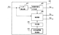
- FIG. 2 is a configuration diagram of the interconnection control circuit 24.
- the interconnection control circuit 24 includes a trigger detection unit 41, an active change provision unit 42, a solar radiation amount information acquisition unit 43, a determination unit 45, a control unit 46, and the like.
- the trigger detection unit 41 continuously monitors electrical fluctuations in the power system, and detects a trigger (a trigger for starting the detection process of the single operation) based on the electrical fluctuations. More specifically, the trigger detection unit 41 operates as follows.
- the trigger detection unit 41 generates a signal representing the power state of the power system (particularly the state of the voltage waveform) based on the input voltage detection signal Vd.
- the items of the power state include, for example, the frequency, phase, amplitude, and harmonic (for example, third, fifth, or seventh harmonic) amplitude of the AC voltage in the power system.
- the signal may be generated not only for one item but for each of a plurality of items.
- the trigger detection part 41 calculates the fluctuation amount of an electric power state based on this produced
- the calculation of the fluctuation amount is realized, for example, by calculating the difference between the instantaneous value and the moving average value, and thereby the amount of fluctuation from the moving average value is calculated.
- the procedure for calculating the fluctuation amount is not limited to this.
- the average of the most recent instantaneous values may be used, or a preset reference value (fixed value) may be used instead of the above-mentioned moving average value. .
- the trigger detection unit 41 compares the fluctuation amount calculation result with a preset determination threshold value.
- This determination threshold is a value that is estimated that an isolated operation has occurred when an electrical fluctuation exceeding that value occurs in the power system.
- the trigger detection unit 41 detects that the calculation result is larger in the comparison result as a trigger. The result of this detection is transmitted to the active change imparting unit 42.
- each calculation result is compared with a determination threshold set for each item.
- a trigger is detected when the calculation result is larger in any one or a plurality of items.
- the active change giving unit 42 changes the change giving signal Sc output to the controller 21 from the L level (zero level) to the H level when the trigger is detected by the trigger detection unit 41.
- the change giving signal Sc is a signal for actively changing the power state of the power system, as will be apparent from the following description.
- the specific value of the H level is an active change having an appropriate magnitude. Is set to be given. Further, when the active change giving unit 42 outputs the H level change giving signal Sc, the active change giving unit 42 notifies the control unit 46 of the fact.
- the solar radiation amount information acquisition unit 43 has a function of acquiring information indicating the solar radiation amount near the own aircraft (hereinafter referred to as “sunlight amount information”) and transmitting the information to the determination unit 45.
- the solar radiation amount information acquiring unit 43 acquires the solar radiation amount information periodically, for example, and sequentially transmits the latest solar radiation amount information to the determination unit 45. A more specific form of the solar radiation amount information acquisition unit 43 will be described in detail again.
- the determination unit 45 determines whether or not the current situation is a lightning warning situation based on the latest solar radiation amount information received from the solar radiation amount information acquisition unit 43.
- the lightning strike warning situation is a situation in which an instantaneous drop due to a lightning strike is likely to occur in the electric power system to which the own device (Powercon 1) is connected.
- the determination is continuously executed, and the latest determination result is transmitted to the control unit 46. Thereby, the control part 46 can identify whether the present condition is a lightning caution situation.
- the determination is specifically performed according to the following procedure.
- the determination unit 45 calculates the rate of decrease in the amount of solar radiation based on the amount of solar radiation information when the current situation is not a lightning warning situation, and whether the calculation result exceeds a preset first threshold value. Determine whether or not. If this calculation result exceeds the first threshold, it is determined that a lightning caution situation has been reached, and if it does not exceed the first threshold, it is determined that the lightning caution situation has not occurred.
- the rate of decrease in the amount of solar radiation is calculated, for example, by the following equation (1).
- T indicates a predetermined time set in advance
- S2 indicates the amount of solar radiation represented by the latest amount of solar radiation information.
- S1 has shown the solar radiation amount which the solar radiation amount information acquired only T before the newest thing represents.
- this calculation method is an example, and other methods may be adopted as long as it is possible to determine a rapid decrease in the amount of solar radiation.
- the above S1 may be a moving average of the amount of solar radiation during the most recent T.
- the determination unit 45 calculates the increase rate of the solar radiation amount based on the solar radiation amount information when the current situation is a lightning strike warning situation, and whether the calculation result exceeds a preset second threshold value. Is determined. If the calculation result exceeds the second threshold, it is determined that the lightning caution situation has been eliminated, and if it does not exceed the second threshold, it is determined that the lightning caution situation still continues.
- the rate of increase in the amount of solar radiation is calculated by, for example, the following equation (2) (the above equation (1) with the sign inverted). (S2-S1) / T (2)
- the first threshold value and the second threshold value are determined in advance by, for example, calculation or experiment so as to be determined as accurately as possible when the solar radiation is blocked by thunderclouds, or when this is eliminated, and recorded in the determination unit 45. Has been. For example, the amount of solar radiation changes gradually due to changes in solar altitude over time, but the first threshold value and the second threshold value are sufficiently larger than the rate of decrease or increase in the amount of solar radiation caused by this. Has been.
- the control unit 46 controls the interconnection relay 19 and the distributed power source 2 based on the voltage detection signal Vd and information transmitted from the active change applying unit 42 and the determination unit 45. Details of the control will be described again.
- the distributed power source 2 includes a plurality of types such as a solar cell (PV), a fuel cell (FC), and a gas turbine generator.
- the power conditioner 1 is divided into two types, a “PV-dedicated type” on the premise that a solar cell is connected as the distributed power source 2 and a “general-purpose type” regardless of the type of the distributed power source 2 to be connected. Different types are available.
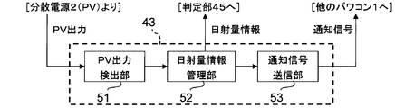
- the solar radiation amount information acquisition unit 43 provided in the “PV dedicated type” power conditioner 1 will be described below with reference to FIG. 3.
- the solar radiation amount information acquisition unit 43 includes a PV output detection unit 51, a solar radiation amount information management unit 52, and a notification signal transmission unit 53.
- the PV output detection unit 51 continuously detects the magnitude of the electric power (PV output) output from the distributed power source 2 that is a solar battery to the power conditioner 1, and notifies the solar radiation amount information management unit 52 of the detection result.
- the solar radiation amount information management unit 52 periodically generates the latest solar radiation amount information based on the information received from the PV output detection unit 51.
- the amount of power generated by the solar cell is an amount corresponding to the amount of solar radiation at that time, and the magnitude of the PV output is determined according to the amount of power generated by the solar cell at that time. Therefore, based on the detection result of the PV output detection unit 51, the power generation amount of the solar cell at that time is found, and consequently the amount of solar radiation is found.
- This transmission flag can be freely set to either “ON” or “OFF” by a user or an operator, for example.
- the transmission flag When the transmission flag is “ON”, the solar radiation amount information generated in the solar radiation amount information management unit 52 is sequentially transmitted to the determination unit 45 and the notification signal transmission unit 53. On the other hand, when the transmission flag is “OFF”, the transmission of the solar radiation amount information to the notification signal transmission unit 53 is omitted.
- the notification signal transmission unit 53 When the transmission flag is “ON”, the notification signal transmission unit 53 generates a notification signal including this information based on the solar radiation amount information received from the solar radiation amount information management unit 52.
- This notification signal is a signal for notifying other apparatus (other power conditioner 1 which is a general-purpose type) of solar radiation amount information.
- the notification signal transmission unit 53 sequentially transmits the generated notification signal to another device by wireless transmission or wired transmission.
- the transmission flag is “OFF”, the operation for generating the notification signal is omitted.
- solar radiation amount information acquisition unit 43 provided in the “PV dedicated type” power conditioner 1, solar radiation amount information representing the solar radiation amount at each time point is acquired based on the power generation amount of the solar cell. It is possible to do. Further, according to the solar radiation amount information acquisition unit 43, a notification signal including the solar radiation amount information can be generated and transmitted to one or a plurality of other devices.
- the information included in the notification signal can be various forms of information as long as the detection result of the power generation amount of the solar cell is reflected.
- the notification signal may include information (determination flag) indicating a result of determining whether the lightning warning situation is based on the detection result.
- the solar radiation amount information acquisition unit 43 determines whether the current time is within the sunshine period (the period in which there is sunshine to the extent that power generation by the solar cell is possible), and within the period in which power generation by the solar cell is possible ( In other words, the solar radiation amount information may be acquired based on the power generation amount of the solar cell only during the sunshine period. Thereby, it becomes possible to avoid performing the operation
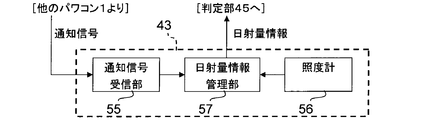
- the solar radiation amount information acquisition unit 43 provided in the “general-purpose type” power conditioner 1 will be described below with reference to FIG.
- the solar radiation amount information acquiring unit 43 includes a notification signal receiving unit 55, an illuminometer 56, and a solar radiation amount information managing unit 57.
- information on the reception flag is recorded. This reception flag can be freely set to either “ON” or “OFF” by a user or an operator, for example.
- the notification signal receiving unit 55 receives the notification signal transmitted from another device (other power conditioner 1 that is a dedicated type for PV), acquires the solar radiation amount information, and receives the solar radiation amount. Tell the information manager 57.
- the reception flag is “OFF”, the operation for receiving the notification signal is omitted.
- the illuminance meter 56 When the reception flag is “OFF”, the illuminance meter 56 continuously measures the illuminance at the position and transmits the measurement result to the solar radiation amount information management unit 57. It is considered that the illuminance meter 56 is installed at a position exposed to sunlight, whereby the measurement result of the illuminance meter 56 is in accordance with the amount of solar radiation at that time. Therefore, based on the measurement result of the illuminometer 56, the amount of solar radiation at that time can be determined. On the other hand, when the reception flag is “ON”, the measurement may be omitted.
- the solar radiation amount information management unit 57 acquires the solar radiation amount information by receiving the solar radiation amount information from the notification signal receiving unit 55 when the reception flag is “ON”. Further, the solar radiation amount information management unit 57 periodically generates the latest solar radiation amount information based on the information received from the illuminometer 56 when the reception flag is “OFF”. The solar radiation amount information acquired or generated by the solar radiation amount information management unit 57 is sequentially transmitted to the determination unit 45.
- the solar radiation amount information acquisition unit 43 provided in the “general-purpose type” power conditioner 1 the solar radiation amount information representing the solar radiation amount at each time point is acquired based on the measurement result of the illuminance meter 56. It is possible. It is also possible to acquire solar radiation information by receiving the notification signal. When receiving the notification signal, it is not necessary to install the illuminance meter 56 at a position where it is exposed to sunlight. For example, even if the power conditioner 1 is installed indoors, it is possible to acquire appropriate solar radiation amount information.
- the above-described transmission flag and reception flag are appropriately set depending on whether or not execution of transmission / reception of a notification signal is desired.
- the “PV-dedicated type” power conditioner 1 and the “general-purpose type” power conditioner 1 are used in the same consumer, it is expected that the transmission / reception of the notification signal is desired.
- the transmission flag and the reception flag in each power conditioner 1 are set to “ON”.
- a communication path used for transmission / reception of the notification signal is appropriately constructed. Thereby, transmission / reception of the notification signal is realized.
- the transmission flag and the reception flag in each power conditioner 1 are set to “OFF”. Thereby, it is possible to omit the operation related to the transmission / reception of the notification signal and to reduce the operation load of the power conditioner 1.
- the power conditioner 1 adjusts the electric power sent from the distributed power supply 2 and continuously performs an operation of outputting the electric power to the power system.
- the state of the power output here must comply with the prescribed interconnection rules. In other words, it is necessary that the distortion factor, power factor, and the like of the output harmonic voltage are within a specified range, and that the waveform of the output current is a sine wave. In addition, the state of the output power is matched with the power state of the power system so that the power state of the power system is not disturbed (that is, the frequency, phase, voltage amplitude, etc. of the alternating current substantially match). It is also necessary to be.
- a series of devices formed by the controller 21, the PWM comparator 22, the triangular wave generation circuit 23, and the like indicate a voltage drop or a voltage state of the power system due to current flow based on the current detection signal Id and the voltage detection signal Vd.
- the gate signal Sg is generated so that such a condition is satisfied.
- the power conditioner 1 controls the inverter circuit 14 by the PWM [Pulse Width Modulation] method, and appropriately adjusts the power transmitted from the distributed power source 2.
- the change giving signal Sc is at the L level (zero level), and does not affect the power adjustment.
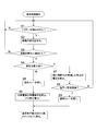
- the trigger detection unit 41 continuously monitors the generation of the trigger based on the electrical fluctuation of the power system (step S1).
- the active change applying unit 42 outputs an H level change applying signal Sc to the controller 21.
- the controller 21 generates a signal corresponding to a combination of the H level change giving signal Sc in addition to the current detection signal Id and the voltage detection signal Vd as a signal representing the inverter operation amount.
- the power output from the power conditioner 1 to the power system is in a state where the power corresponding to the active change is added to the state matched with the power state of the power system.
- an active change is given to the power state of the power system (step S2).
- the time during which the change applying signal Sc is maintained at the H level, that is, the time during which the active change is applied, is set to be equal to or greater than the time Ta described later.
- control unit 46 monitors the power state of the power system based on the voltage detection signal Vd. Then, when a predetermined time Ta (for example, 0.3 seconds) has elapsed from the start of the application of the active change, it is determined whether or not the power state follows the active change (step S3). Since this discrimination method is based on the conventional detection method using the active detection method, a detailed description is omitted here.
- a predetermined time Ta for example, 0.3 seconds
- control part 46 discriminate
- the control unit 46 determines whether or not the current state is a lightning strike warning situation (whether or not an instantaneous drop due to a lightning strike is likely to occur). Depending on the operation, a different operation is performed (step S4). That is, when it is not a lightning caution situation (N in Step S4), the control unit 46 determines that an isolated operation state has occurred, and outputs a relay switching signal Sr for opening the interconnection relay 19 (Step S5). . Further, the control unit 46 (except for the case of “PV exclusive type”) outputs a power generation stop signal Se when the type of the distributed power source 2 connected to the own unit is FC or a gas turbine generator. Then, the power generation operation of the distributed power supply 2 is stopped (step S6).
- the control unit 46 does not immediately determine that the single operation state has occurred, and further, for a predetermined time Tb (for example, 0.2 seconds).
- the voltage of the electric power system at the time when elapses is detected (step S7).
- Step S3 the determination result in Step S3 is caused by the instantaneous drop (therefore, the isolated operation state caused by the normal power failure or the like is It does not occur). In this case, the operation of step S1 is repeated without the interconnection relay 19 being opened.
- step S8 if the detected voltage is below the predetermined threshold (Y in step S8), that is, if the voltage abnormality of the power system continues even after the elapse of time Tb, the single voltage caused by a normal power failure or the like It is determined that an operating state has occurred. Therefore, the control unit 46 outputs a relay switching signal Sr for opening the interconnection relay 19 (step S9).
- step S3 may be attributed to an instantaneous drop (particularly, the duration is longer than the sum of the times Ta and Tb). Moreover, since there is a lightning strike warning situation, there is a relatively high possibility that such an instantaneous drop occurs frequently. In addition, FCs and gas turbine generators are likely to deteriorate due to abrupt stop or restart, or require a relatively long time from startup to start of output. Therefore, the control unit 46 prevents the operation corresponding to step S6 (operation that outputs the power generation stop signal Se and stops the power generation operation of the distributed power source 2) from being executed.
- step S6 or S9 is performed, for example, after confirming the cancellation of the isolated operation state, the interconnection is restored, and the operation of step S1 is repeated.
- a predetermined voltage sag response operation is performed. More specifically, even if the condition that the power state of the power system follows an active change is satisfied (Y in step S3), this does not open the connection relay (connection to the power system). Is performed as one of the operations corresponding to the instantaneous drop.
- Step S5 If it is a lightning warning situation, the interconnection relay 19 is not opened. For this reason, the occurrence of frequent disconnection of the power conditioner 1 due to such an instantaneous drop is avoided. As a result, in the power transmission system, it is avoided as much as possible that a large number of power conditioners 1 are disconnected at the same time due to the instantaneous drop.
- the voltage of the power system is detected when the time Tb has passed since the condition is satisfied, and when the voltage is below a predetermined threshold, the connection relay is opened (connection to the power system). Is also performed as one of the operations corresponding to the instantaneous drop. Thereby, even if it is a lightning caution situation, when a normal power failure etc. generate
- the discrimination time is approximately the time Ta in a situation that is not a lightning caution situation
- the discrimination period is The time is approximately the sum of time Ta and Tb.
- the power conditioner 1 (excluding the “PV exclusive type”), when the connection with the power system is canceled, the type of the distributed power source 2 connected to the own machine is a specific type such as FC or gas turbine generator.
- a process (stop process) for stopping the power generation operation of the distributed power supply 2 is performed (step S6).
- the power conditioner 1 performs an operation for preventing the stop process from being executed in a lightning strike warning situation as one of the operations for dealing with the instantaneous drop.
- the detection of the isolated operation is performed by the already described trigger method.
- the present invention is not limited to this. Other methods such as an automatic detection method may be employed.
- the power conditioner 1 described so far is used in each customer to link the distributed power source 2 to the power system (bank).
- a “general-purpose type” power conditioner 1 is used in each consumer.
- a solar cell is connected as the distributed power source 2
- a “PV dedicated type” or “general-purpose type” power conditioner 1 is used in each consumer.
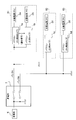
- FIG. 6 shows a power transmission system to which the power conditioner 1 is connected.
- the power from the power plant 6 is transmitted to the substation 7 through the high-voltage power transmission line, and the substation 7 has a plurality of banks (transmission lines to each customer, (Corresponding to the electric power system seen from the house).
- electric power is transmitted to the consumer 81 by the bank A, and to the consumer 82 and the consumer 83 by the bank B.
- the power source 1 (1a) dedicated to PV is used for the distributed power source 2a. Is connected to the power system, and the distributed power source 2b is connected to the power system using the general-purpose type power conditioner 1 (1b).
- the transmission flag described above is set to “ON” for the power conditioner 1a
- the reception flag described above is set to “ON” for the power conditioner 1b.
- a communication path for a notification signal is established between these power conditioners (1a, 1b).
- the power conditioner 1a operates to acquire the solar radiation amount information based on the power generation amount of the distributed power source 2a (solar battery) and to transmit a notification signal to the power conditioner 1b.
- the power conditioner 1b operates to acquire solar radiation amount information based on the received notification signal.
- both power conditioners (1a, 1b) can acquire the amount of solar radiation information, and based on this information, it is possible to determine whether or not a lightning strike situation is present.
- the power conditioner 1b since it is not necessary to install the illuminance meter 56 in the position which hits sunlight, you may install in the room
- these power conditioners (1a, 1b) when viewed as a unit, they can be regarded as a grid-connected system that is set in advance so as to transmit and receive notification signals.
- an example in which one power conditioner 1b receives a notification signal from the power conditioner 1a (transmission side apparatus) has been shown, but a plurality of general-purpose power conditioners may receive a notification signal from the power conditioner 1a. good.
- the distributed power source 2c since the customer 82 uses the distributed power source 2 (2c) which is a fuel cell, the distributed power source 2c is connected to the power system using the general-purpose type power conditioner 1 (1c). In the power conditioner 1c, the reception flag is set to “OFF”. Thereby, the power conditioner 1c can acquire the amount of solar radiation information based on the measurement result of the illuminance meter 56, and based on this information, it is possible to determine whether or not it is a lightning strike warning situation.
- the distributed power source 2d since the customer 83 uses the distributed power source 2 (2d) which is a solar cell, the distributed power source 2d is connected to the power system using the PV power type 1 (1d). .
- the transmission flag is set to “OFF”.
- the power conditioner 1c can acquire the amount of solar radiation information based on the power generation amount of the distributed power source 2d (solar cell), and can determine whether or not it is a lightning warning situation based on this information. It has become.
- the consumer 83 can use the general-purpose type power conditioner 1 instead of the PV-specific type power conditioner 1 when using the distributed power source 2 (2d) which is a solar battery.
- the reception flag may be set to “OFF”.
- the power conditioner 1 is a device that is connected to the power system and outputs the power generated by the connected distributed power source 2 to the power system, and reduces the amount of solar radiation.
- a lightning strike warning situation a situation in which the power system is prone to a momentary drop due to a lightning strike
- the lightning caution situation is a situation in which the risk of an instantaneous drop due to lightning is increased.
- the “PV dedicated type” power conditioner 1 is connected to a solar cell as the distributed power source 2, and the status detection unit recognizes the rate of decrease in the amount of solar radiation based on the amount of power generated by the solar cell. For this reason, it is not necessary to separately provide means (for example, an illuminometer) for acquiring information on the amount of solar radiation, and it is easy to reduce the size of the apparatus and reduce the manufacturing cost.
- the “PV dedicated type” power conditioner 1 when the transmission flag is “ON”, the “PV dedicated type” power conditioner 1 generates a notification signal reflecting the detection result of the power generation amount of the solar cell, and this notification signal is transmitted to the other device (“general-purpose type”). To the power control 1). Therefore, the information of the detection result acquired by the own device can be used in other devices and can be used more effectively.
- the “PV dedicated type” power conditioner 1 may have a specification in which the function of transmitting a notification signal is omitted.
- the “general-purpose type” power conditioner 1 receives a notification signal from another device (“PV exclusive type” power conditioner 1), and based on the information obtained by this reception, the solar radiation is received. It is determined that the amount decrease rate exceeds a predetermined threshold value. Further, the “general-purpose type” power conditioner 1 includes an illuminance meter 56, and when the reception flag is “OFF”, the rate of decrease in the amount of solar radiation through the measurement result of illuminance by the illuminance meter 56 (based on the measurement result). Recognize
- the “general-purpose type” power conditioner 1 in the present embodiment has a function of determining that the rate of decrease in the amount of solar radiation has exceeded a predetermined threshold based on information obtained by receiving the notification signal, and the illuminance by the illuminometer. Although it has both the function of recognizing the rate of decrease in solar radiation through the measurement result, it is also possible to have a specification in which either one is omitted.
- the “PV dedicated type” power conditioner 1 may be provided with a function of generating and transmitting a notification signal.
- the “general-purpose type” power conditioner 1 generates a notification signal reflecting the measurement result of the illuminance by the illuminance meter 56, and transmits this notification signal to another device. In this way, the measurement result information can be used in other devices, and this information can be used more effectively.
- the power conditioner 1 acquires the amount of solar radiation information by itself or by a notification signal received from another power conditioner 1 and detects that a lightning warning situation has occurred. It has become. Therefore, for example, it is possible to cause the power conditioner 1 to perform the detection without separately preparing a facility for providing some information to the power conditioner 1 or giving any information to the power conditioner 1 by the user.
- the solar cell (PV), the fuel cell (FC), and the gas turbine generator are cited as the types of the distributed power source.
- the distributed power source may be one that can output power, such as a secondary battery.
- the power conditioner was mentioned as a power converter device, it is not limited to this.
- a power conversion device that directly converts AC power into predetermined AC power, such as a cycloconverter or a matrix converter, may be used.
- the power conditioner 1 is not only used for general households but also used by various types of consumers including medium-sized consumers such as various stores, apartment houses, government buildings, and schools. Can be done. Moreover, the power conditioner 1 can contribute to promotion of a school new deal concept by being applied to a power supply system in a school together with a solar battery and the like.
- FCs are difficult to start and stop quickly due to their characteristics.
- the power conditioner 1 may perform the following operation (1) or (2) as an operation corresponding to the instantaneous drop.
- (1) Do not open the interconnection relay 19 (do not disconnect from the power system) and continue the operation as it is.
- the interconnection relay 19 is immediately opened (immediately disconnected from the power system), and the generated power of the FC is turned to a heater of a hot water tank or the like. Thereby, rapid start-up and operation stop in FC can be prevented in advance.
- the amount of power generation of the solar cell or the measurement result of the illuminometer is used as information correlated with the amount of solar radiation (referred to as “sunlight amount parameter”), but is not limited thereto. It is not a thing.
- a solar radiation amount parameter an infrared ray (radiant heat) amount, an ultraviolet ray amount, or a detected value of the amount of electromagnetic waves contained in other solar rays may be used.
- the solar radiation amount parameter for example, a detection value such as a reception level of a BS broadcast signal (decreases because signal transmission is inhibited as the number of clouds increases) or atmospheric pressure (decreases as cloud tends to increase) is used. May be.
- output characteristics of the solar cell for example, any detected value of the maximum power point (Pmax), the open circuit voltage, and the short circuit current, or the amount of change thereof may be used.
- information on the current time may be referred to.
- the power conditioner 1 uses each of the solar radiation amount parameters as an example to determine the lightning caution situation by the following determination methods (A) to (C).
- A) If any one of the solar radiation amount parameters satisfies the predetermined condition (that is, by the OR condition determination method), it is determined that the lightning strike warning situation is present.
- B) If all the solar radiation amount parameters satisfy the predetermined condition (that is, according to the AND condition determination method), it is determined that the lightning strike warning situation is present.
- C If more than half of the solar radiation amount parameters satisfy the predetermined condition (that is, according to the majority decision method), it is determined that there is a lightning strike warning situation.
- the present invention can be used for a power conditioner connected to an electric power system.
Landscapes
- Engineering & Computer Science (AREA)
- Power Engineering (AREA)
- Supply And Distribution Of Alternating Current (AREA)
- Charge And Discharge Circuits For Batteries Or The Like (AREA)
- Inverter Devices (AREA)
Abstract
Description
次にパワコン1の構成等について説明する。図1に示すようにパワコン1は、ダイオード11、コンデンサ12、インバータ回路14、インダクタ15、コンデンサ16、電流検出回路17、電圧検出回路18、連系リレー19、制御器21、PWMコンパレータ22、三角波生成回路23、および連系制御回路24などを備えている。
-(S2-S1)/T ・・・(1)
ここで、Tは予め設定された一定時間を、S2は最新の日射量情報が表す日射量を、それぞれ示している。またS1は、最新のものよりTだけ前に取得された日射量情報が表す、日射量を示している。但しこの算出手法は一例であり、日射量の急激な減少を判定することが可能となっている限り、他の手法が採用されても構わない。例えば上記のS1を、直近のTの間における日射量の移動平均としても構わない。
(S2-S1)/T ・・・(2)
ところで先述したように、分散電源2は、太陽電池(PV)、燃料電池(FC)、およびガスタービン発電機などの複数種が存在する。これを考慮してパワコン1は、分散電源2として太陽電池が接続されることを前提とした「PV専用タイプ」と、接続される分散電源2の種類を問わない「汎用タイプ」との、二種類のタイプが用意されている。
次にパワコン1が行う主な動作について説明する。パワコン1は基本動作として、分散電源2から送られてくる電力を調整し、電力系統へ出力する動作を継続的に行う。
ところで単独運転状態が発生したときには、分散電源2を電力系統から解列させる必要がある。そこでパワコン1は上述した基本動作の実行に並行し、単独運転状態の発生の有無を的確に判別して、必要に応じて電力系統との連系を解除させる動作(連系制御動作)をも実行する。この連系制御動作の流れについて、図5に示すフローチャートを参照しながら以下に説明する。
これまでに説明したパワコン1は、各需要家において、分散電源2を電力系統(バンク)へ連系させるために用いられる。また各需要家において、分散電源2として燃料電池やガスタービン発電機(太陽電池以外のもの)を連系させる場合には、「汎用タイプ」のパワコン1が利用される。また分散電源2として太陽電池を連系させる場合には、「PV専用タイプ」または「汎用タイプ」のパワコン1が利用される。
以上までに説明した通り、本実施形態に係るパワコン1は、電力系統に連系し、接続されている分散電源2が発電した電力をこの電力系統へ出力する装置であって、日射量の減少速度が所定閾値を超えたことを判別することにより、落雷注意状況(電力系統において落雷による瞬低が発生し易くなっている状況)になったことを検出するとともに、落雷注意状況において、予め定められた瞬低対応動作を行うようになっている。なお落雷注意状況は、落雷による瞬低発生の危険性が高まった状況であるとも言う事が出来る。
(1)連系リレー19を開かず(電力系統から解列せず)、そのままの動作を継続する。
(2)連系リレー19を即時に開き(電力系統から即時解列し)、FCの発電電力を貯湯槽のヒータ等に回す。
これにより、FCにおける急速な起動や動作停止を、未然に防ぐことが可能である。
(A)各日射量パラメータのうちの何れかが所定条件を満たしていれば(つまりOR条件の判定方式により)、落雷注意状況であると判定する。
(B)各日射量パラメータの全てが所定条件を満たしていれば(つまりAND条件の判定方式により)、落雷注意状況であると判定する。
(C)各日射量パラメータのうちの半数以上が所定条件を満たしていれば(つまり多数決の判定方式により)、落雷注意状況であると判定する。
2、2a~2d 分散電源
5 負荷
6 発電所
7 変電所
11 ダイオード
12 コンデンサ
14 インバータ回路
15 インダクタ
16 コンデンサ
17 電流検出回路
18 電圧検出回路
19 連系リレー
21 制御器
22 PWMコンパレータ
23 三角波生成回路
24 連系制御回路
41 トリガー検出部
42 能動的変化付与部
43 日射量情報取得部
45 判定部
46 制御部
51 PV出力検出部
52 日射量情報管理部
53 通知信号送信部
55 通知信号受信部
56 照度計
57 日射量情報管理部
81~83 需要家
Claims (8)
- 電力系統に連系し、接続されている分散電源が発電した電力を該電力系統へ出力する系統連系装置であって、
日射量の減少速度が所定閾値を超えたことを判別し、該判別の結果に応じて、予め定められた瞬低対応動作を行う系統連系装置。 - 前記分散電源として、太陽電池が接続される請求項1に記載の系統連系装置であって、
前記太陽電池の発電量に基づいて、日射量の減少速度を認識する系統連系装置。 - 前記太陽電池の発電量の検出結果を反映させた通知信号を生成し、
前記通知信号を、他機に向けて送信する請求項2に記載の系統連系装置。 - 他機としての系統連系装置から信号を受信し、
前記受信によって得られた情報に基づいて、日射量の減少速度が前記閾値を超えたことを判別する請求項1に記載の系統連系装置。 - 照度計を備えており、
該照度計による照度の測定結果を通じて、日射量の減少速度を認識する請求項1に記載の系統連系装置。 - 前記照度計による照度の測定結果を反映させた通知信号を生成し、
前記通知信号を、他機に向けて送信する請求項5に記載の系統連系装置。 - 前記電力系統の電力状態を検出し、該電力状態が予め定められた条件を満たしたときに、前記電力系統との連系を解除させる連系制御部を備え、
前記連系制御部は、前記瞬低対応動作として、
前記電力状態が前記条件を満たしたことによっては、前記電力系統との連系を解除させないようにする一方、
前記電力状態が前記条件を満たした時から、更に所定時間が経過した時の前記電力系統の電圧を検出し、
該電圧が所定閾値を下回っていたときに、前記電力系統との連系を解除させる動作を行う請求項1に記載の系統連系装置。 - 請求項3に記載の系統連系装置である1個の送信側装置と、
各々が前記送信側装置から送信された前記通知信号を受信する、請求項4に記載の系統連系装置の複数個と、
を有する系統連系システム。
Priority Applications (2)
| Application Number | Priority Date | Filing Date | Title |
|---|---|---|---|
| JP2012536463A JP5857206B2 (ja) | 2010-09-28 | 2011-09-27 | 系統連系装置および系統連系システム |
| EP11829081.6A EP2624404A4 (en) | 2010-09-28 | 2011-09-27 | System connection device and system connection system |
Applications Claiming Priority (2)
| Application Number | Priority Date | Filing Date | Title |
|---|---|---|---|
| JP2010217885 | 2010-09-28 | ||
| JP2010-217885 | 2010-09-28 |
Publications (1)
| Publication Number | Publication Date |
|---|---|
| WO2012043528A1 true WO2012043528A1 (ja) | 2012-04-05 |
Family
ID=45892969
Family Applications (1)
| Application Number | Title | Priority Date | Filing Date |
|---|---|---|---|
| PCT/JP2011/071993 Ceased WO2012043528A1 (ja) | 2010-09-28 | 2011-09-27 | 系統連系装置および系統連系システム |
Country Status (3)
| Country | Link |
|---|---|
| EP (1) | EP2624404A4 (ja) |
| JP (1) | JP5857206B2 (ja) |
| WO (1) | WO2012043528A1 (ja) |
Cited By (1)
| Publication number | Priority date | Publication date | Assignee | Title |
|---|---|---|---|---|
| WO2014140962A1 (en) * | 2013-03-14 | 2014-09-18 | Koninklijke Philips N.V. | Solar power supply system |
Families Citing this family (1)
| Publication number | Priority date | Publication date | Assignee | Title |
|---|---|---|---|---|
| CN109066797B (zh) * | 2018-09-12 | 2021-10-08 | 云南电网有限责任公司 | 含光伏发电的电力系统运行控制方法及装置 |
Citations (3)
| Publication number | Priority date | Publication date | Assignee | Title |
|---|---|---|---|---|
| JP2000350369A (ja) * | 1999-06-03 | 2000-12-15 | Nissin Electric Co Ltd | 分散電源の単独運転検出装置 |
| JP2001169565A (ja) * | 1999-12-07 | 2001-06-22 | Aichi Electric Co Ltd | 系統連系用電力変換システム |
| JP2003090887A (ja) * | 2001-09-20 | 2003-03-28 | Ffc:Kk | 落雷による瞬時電圧低下予測システムおよび予測方法 |
Family Cites Families (7)
| Publication number | Priority date | Publication date | Assignee | Title |
|---|---|---|---|---|
| JP3053040U (ja) * | 1998-04-08 | 1998-10-13 | 茂徳 岩井田 | 物干し装置 |
| JP2000156935A (ja) * | 1998-11-18 | 2000-06-06 | Tokyo Gas Co Ltd | 自家発電設備の制御方法及び制御装置 |
| US6291764B1 (en) * | 1999-03-24 | 2001-09-18 | Sanyo Electronics Co., Ltd. | Photovoltaic power generation device |
| JP2006101604A (ja) * | 2004-09-28 | 2006-04-13 | Chugoku Electric Power Co Inc:The | 電力品質予測システム |
| JP2006246620A (ja) * | 2005-03-03 | 2006-09-14 | Tokyo Electric Power Co Inc:The | 分散型電源装置、その制御システム、および分散型電源の制御方法 |
| US7502241B2 (en) * | 2005-04-07 | 2009-03-10 | Pv Powered, Inc. | Inverter startup algorithm |
| TWI384720B (zh) * | 2008-07-17 | 2013-02-01 | 行政院原子能委員會 核能研究所 | 家用負載之直流電力裝置 |
-
2011
- 2011-09-27 WO PCT/JP2011/071993 patent/WO2012043528A1/ja not_active Ceased
- 2011-09-27 JP JP2012536463A patent/JP5857206B2/ja active Active
- 2011-09-27 EP EP11829081.6A patent/EP2624404A4/en not_active Withdrawn
Patent Citations (3)
| Publication number | Priority date | Publication date | Assignee | Title |
|---|---|---|---|---|
| JP2000350369A (ja) * | 1999-06-03 | 2000-12-15 | Nissin Electric Co Ltd | 分散電源の単独運転検出装置 |
| JP2001169565A (ja) * | 1999-12-07 | 2001-06-22 | Aichi Electric Co Ltd | 系統連系用電力変換システム |
| JP2003090887A (ja) * | 2001-09-20 | 2003-03-28 | Ffc:Kk | 落雷による瞬時電圧低下予測システムおよび予測方法 |
Non-Patent Citations (1)
| Title |
|---|
| See also references of EP2624404A4 * |
Cited By (1)
| Publication number | Priority date | Publication date | Assignee | Title |
|---|---|---|---|---|
| WO2014140962A1 (en) * | 2013-03-14 | 2014-09-18 | Koninklijke Philips N.V. | Solar power supply system |
Also Published As
| Publication number | Publication date |
|---|---|
| EP2624404A1 (en) | 2013-08-07 |
| JP5857206B2 (ja) | 2016-02-10 |
| JPWO2012043528A1 (ja) | 2014-02-24 |
| EP2624404A4 (en) | 2017-08-02 |
Similar Documents
| Publication | Publication Date | Title |
|---|---|---|
| US8352084B2 (en) | Renewable electricity generation system, electric power measurement device and method | |
| JP5763407B2 (ja) | 異常検出装置、およびこの異常検出装置を備えた発電システム | |
| US9954370B2 (en) | Electrical grid control system, electrical grid control method, and power conversion apparatus | |
| KR102004413B1 (ko) | 채널 감시형 접속반을 구비하는 태양광 발전 모니터링 시스템 | |
| US8110941B2 (en) | Power demand management method and system | |
| KR20150070353A (ko) | 양방향 전원 시스템, 동작 방법, 및 동작 제어기 | |
| JP5885711B2 (ja) | 分散電源設備システム | |
| US9997920B2 (en) | System and method for islanding detection and prevention in distributed generation | |
| US10069304B2 (en) | System and method for islanding detection and prevention in distributed generation | |
| RU2747622C2 (ru) | Способ управления распределительной электрической микросетью, носитель информации, компьютерное устройство и устройство управления | |
| JP2011229368A (ja) | 制御装置および制御方法 | |
| US10951039B2 (en) | Multi-input PV inverter system and method | |
| JP6429691B2 (ja) | 太陽光発電システムおよびパワーコンディショナ | |
| EP2871750B1 (en) | Electrical power management device and electrical power management method | |
| WO2014051075A1 (ja) | 制御システム、制御装置、及び制御方法 | |
| US9804212B2 (en) | Energy management system | |
| US20250167586A1 (en) | Energy coupling method and system for household energy storage | |
| JP6574651B2 (ja) | 電力制御装置 | |
| JP5857206B2 (ja) | 系統連系装置および系統連系システム | |
| KR20150124325A (ko) | 가정용 태양광 에너지 거래를 위한 시스템 및 방법 | |
| JP6527681B2 (ja) | パワーコンディショナ、その電力制御方法、及び電力制御システム | |
| JP7019335B2 (ja) | 電圧制御装置、電圧制御方法及び電圧制御プログラム | |
| JP2017099235A (ja) | 電力変換システム及び制御装置 | |
| JP5872353B2 (ja) | エネルギー管理システム及びエネルギー管理方法 | |
| CN118137548A (zh) | 一种户用三相储能一体机系统 |
Legal Events
| Date | Code | Title | Description |
|---|---|---|---|
| 121 | Ep: the epo has been informed by wipo that ep was designated in this application |
Ref document number: 11829081 Country of ref document: EP Kind code of ref document: A1 |
|
| ENP | Entry into the national phase |
Ref document number: 2012536463 Country of ref document: JP Kind code of ref document: A |
|
| NENP | Non-entry into the national phase |
Ref country code: DE |
|
| REEP | Request for entry into the european phase |
Ref document number: 2011829081 Country of ref document: EP |
|
| WWE | Wipo information: entry into national phase |
Ref document number: 2011829081 Country of ref document: EP |