WO2012046598A1 - セラミックチューブ及びその製造方法 - Google Patents
セラミックチューブ及びその製造方法 Download PDFInfo
- Publication number
- WO2012046598A1 WO2012046598A1 PCT/JP2011/072113 JP2011072113W WO2012046598A1 WO 2012046598 A1 WO2012046598 A1 WO 2012046598A1 JP 2011072113 W JP2011072113 W JP 2011072113W WO 2012046598 A1 WO2012046598 A1 WO 2012046598A1
- Authority
- WO
- WIPO (PCT)
- Prior art keywords
- ceramic
- capillary
- tube
- axis
- molded body
- Prior art date
- Legal status (The legal status is an assumption and is not a legal conclusion. Google has not performed a legal analysis and makes no representation as to the accuracy of the status listed.)
- Ceased
Links
Images


Classifications
-
- B—PERFORMING OPERATIONS; TRANSPORTING
- B28—WORKING CEMENT, CLAY, OR STONE
- B28B—SHAPING CLAY OR OTHER CERAMIC COMPOSITIONS; SHAPING SLAG; SHAPING MIXTURES CONTAINING CEMENTITIOUS MATERIAL, e.g. PLASTER
- B28B1/00—Producing shaped prefabricated articles from the material
- B28B1/002—Producing shaped prefabricated articles from the material assembled from preformed elements
-
- B—PERFORMING OPERATIONS; TRANSPORTING
- B28—WORKING CEMENT, CLAY, OR STONE
- B28B—SHAPING CLAY OR OTHER CERAMIC COMPOSITIONS; SHAPING SLAG; SHAPING MIXTURES CONTAINING CEMENTITIOUS MATERIAL, e.g. PLASTER
- B28B1/00—Producing shaped prefabricated articles from the material
- B28B1/24—Producing shaped prefabricated articles from the material by injection moulding
-
- H—ELECTRICITY
- H01—ELECTRIC ELEMENTS
- H01J—ELECTRIC DISCHARGE TUBES OR DISCHARGE LAMPS
- H01J61/00—Gas-discharge or vapour-discharge lamps
- H01J61/02—Details
- H01J61/30—Vessels; Containers
- H01J61/302—Vessels; Containers characterised by the material of the vessel
-
- H—ELECTRICITY
- H01—ELECTRIC ELEMENTS
- H01J—ELECTRIC DISCHARGE TUBES OR DISCHARGE LAMPS
- H01J7/00—Details not provided for in the preceding groups and common to two or more basic types of discharge tubes or lamps
- H01J7/14—Means for obtaining or maintaining the desired pressure within the vessel
- H01J7/22—Tubulations therefor, e.g. for exhausting; Closures therefor
-
- H—ELECTRICITY
- H01—ELECTRIC ELEMENTS
- H01J—ELECTRIC DISCHARGE TUBES OR DISCHARGE LAMPS
- H01J9/00—Apparatus or processes specially adapted for the manufacture, installation, removal, maintenance of electric discharge tubes, discharge lamps, or parts thereof; Recovery of material from discharge tubes or lamps
- H01J9/24—Manufacture or joining of vessels, leading-in conductors or bases
- H01J9/245—Manufacture or joining of vessels, leading-in conductors or bases specially adapted for gas discharge tubes or lamps
- H01J9/247—Manufacture or joining of vessels, leading-in conductors or bases specially adapted for gas discharge tubes or lamps specially adapted for gas-discharge lamps
-
- H—ELECTRICITY
- H01—ELECTRIC ELEMENTS
- H01J—ELECTRIC DISCHARGE TUBES OR DISCHARGE LAMPS
- H01J9/00—Apparatus or processes specially adapted for the manufacture, installation, removal, maintenance of electric discharge tubes, discharge lamps, or parts thereof; Recovery of material from discharge tubes or lamps
- H01J9/24—Manufacture or joining of vessels, leading-in conductors or bases
- H01J9/26—Sealing together parts of vessels
- H01J9/265—Sealing together parts of vessels specially adapted for gas-discharge tubes or lamps
- H01J9/266—Sealing together parts of vessels specially adapted for gas-discharge tubes or lamps specially adapted for gas-discharge lamps
-
- H—ELECTRICITY
- H01—ELECTRIC ELEMENTS
- H01J—ELECTRIC DISCHARGE TUBES OR DISCHARGE LAMPS
- H01J9/00—Apparatus or processes specially adapted for the manufacture, installation, removal, maintenance of electric discharge tubes, discharge lamps, or parts thereof; Recovery of material from discharge tubes or lamps
- H01J9/38—Exhausting, degassing, filling, or cleaning vessels
- H01J9/395—Filling vessels
Definitions
- the present invention relates to a method for producing a ceramic tube used for a high-intensity discharge lamp such as a high-pressure sodium lamp or a metal halide lamp, and a ceramic tube.
- a ceramic metal halide lamp ionizes a metal halide with a pair of electrodes inserted in a ceramic tube for a high-intensity discharge lamp, thereby obtaining discharge light emission.
- This type of ceramic tube has a pair of tubules formed so that each axis is positioned so as to face the light emitting portion. Each thin tube is provided with an electrode insertion hole, and an electrode is inserted through these electrode insertion holes.
- Various types of ceramic tubes are disclosed, such as those produced by assembling a plurality of members, those produced integrally as a single member, and those produced by joining two members (for example, JP 63-143738, JP 5-334962, JP 7-21990, JP 8-55606, JP 2010-514125, JP 2010-514127, US (See Japanese Patent Application Publication No. 2006/0001346, JP-T 2009-530127, JP-A 2008-44344).
- the electrode is inserted into one electrode insertion hole and sealed with frit glass or the like, and then the luminescent substance is introduced through the remaining electrode insertion hole.
- an electrode is inserted into the other electrode insertion hole and sealed with frit glass or the like to assemble the luminous tube.
- the third capillaries for introducing the luminescent substance into the luminescent container in order to introduce the luminescent substance after sealing the electrode or A structure is also known in which pores are provided separately from the thin tubes for inserting electrodes.
- Japanese Patent Application Laid-Open No. 63-143738 discloses that both ends of an arc tube bulb made of translucent ceramic are sealed by solid-phase bonding with a closed body made of a conductive cermet that supports the electrodes.
- Japanese Patent Laid-Open No. 5-334962 discloses that closed bodies are respectively attached to cylindrical openings at both ends of a translucent valve made of polycrystalline alumina, and holes through which electrodes pass respectively are provided at the central positions of the closed bodies.
- An example is disclosed in which an opening for introducing a luminescent substance into a translucent bulb is formed at a position that is formed and decentered from the center of one closing member.
- Japanese Patent Application Laid-Open No. 7-21990 discloses an example in which pin-shaped current conductors having a diameter of 300 ⁇ m are inserted into both ends of a discharge tube, and plugs at both ends are directly joined to both ends by sintering.
- 3 and 4 show an example in which a filling hole having a diameter of 1 mm or more for introducing a luminescent substance into the discharge tube is formed in the wall portion of the discharge tube near the second end portion or the second plug. .
- a small-diameter tube whose lower end is closed downward from the center portion of the funnel-shaped portion of the arc tube is integrally suspended to provide a lower portion in the small-diameter tube (during lighting).
- the liquid metal halide that remains in the arc tube without being evaporated is stored in the coldest part: the coldest part).
- one of the openings provided in the flange-shaped intermediate part that is removed from the coldest part is used as an inlet for sealing the metal halide and mercury in the arc tube, and the small-diameter pipe is used as the inlet pipe.
- the inlet pipe There is a description that it can also be used.
- one end of the discharge vessel and the wall of the tube are made as an integral part of the discharge vessel, and the other end of the discharge vessel is sealed with a ceramic end plug.
- a ceramic burner is disclosed.
- a tube is provided on the ceramic wall of the discharge vessel for introducing the ionized filler into the discharge vessel during the production of the ceramic burner and which projects outwardly from the ceramic wall of the discharge vessel. Examples have been disclosed.
- the tube is hermetically sealed.
- the discharge vessel is made, for example, substantially spherical or substantially elliptical by two different parts (separated by a broken line in FIG. 2A of the publication) Only a portion of one discharge vessel is provided with a tube for introducing an ionized filler into the discharge vessel during the production of the ceramic burner and protruding outward from the ceramic wall of the discharge vessel Examples have been disclosed.
- the tube is hermetically sealed.
- U.S. Patent Application Publication No. 2006/0001346 has a cylindrical portion and end members respectively coupled to both ends of the cylindrical portion, and inward of the cylindrical portion at the center of each end member.
- An example in which an electrode extending in the direction is provided is disclosed, and in particular, one end member is provided with an introduction hole penetrating from the outer surface of the end member to the inner surface (the surface facing the inside of the tube portion). Yes.
- the introduction of the metal halide or the like into the cylindrical portion is performed through the introduction hole, and then the introduction hole is sealed with a plug member.
- a slurry can be applied to the joint surfaces of a plurality of inorganic powder compacts, and a plurality of compacts can be butted together to be integrated and sintered, whereby a strong joint sintered body can be obtained.
- JP-T-2009-530127 structures capable of obtaining a bonded inorganic powder molded body while suppressing or avoiding deformation of the bonded portion and increase in surface roughness (for example, JP, 2008-44344, A).
- JP-T-2009-530127 discloses a method for producing a sintered body suitable for use in an arc tube of a discharge lamp, containing an inorganic powder, an organic dispersion medium having a reactive functional group, and a gelling agent.
- Japanese Patent Application Laid-Open No. 2008-44344 discloses a sintered body suitable for use in an arc tube of a discharge lamp, and a sintered body of a joined body of two or more inorganic powder molded bodies is used as two or more of the joined bodies.
- the second component has a surface roughness equal to or less than that of the first component.
- the second constituent part has a light transmission greater than that of the first constituent part in the vicinity of the width center thereof.
- an electrode is provided in the light emitting portion.
- a first capillary and a second capillary for introducing and sealing, and a third capillary (or third pore) for introducing a luminescent substance into the light emitting part are provided.
- a first through hole, a second through hole, and a third through hole are formed in the first thin tube, the second thin tube, and the third thin tube, respectively, along the axial direction.
- the axial direction of the first capillary tube and the second capillary tube is different from the axial direction of the third capillary tube (or the third pore). Therefore, when a molded body that is the basis of the ceramic tube is produced by a method such as injection molding or gel casting, a pin for forming the first through hole and the second through hole and the third through hole (or the third pore) ) Is different, the molding machine mechanism needs to be configured accordingly, and complicated and expensive manufacturing equipment is required. This causes an increase in manufacturing cost.
- the part where the narrow tube and the pore are provided has a lower light transmittance than the other part, so if it is installed at a position corresponding to the discharge area between the electrode tips, the light transmittance deteriorates. However, this is not desirable because it causes a decrease in lamp efficiency and light distribution.
- it if it is installed close to the first capillary or the second capillary for electrode sealing, it tends to be the coldest spot during lighting, and the luminescent material accumulates in the capillary and pores, causing corrosion of the ceramic part, This will cause a decrease in the service life.
- a third tube having the same axial direction is separately provided in advance from the first tube or the second tube for electrode sealing.
- the pores are located in the thick part near the electrode, causing corrosion due to the coldest spot. Therefore, it is not desirable.
- the third thin tube is too long, the temperature does not rise during lighting and the coldest spot is reached, so that the ceramic part is corroded as described above, which is not desirable.
- the present invention has been made in consideration of such a problem, and although it has third pores or third capillaries for introducing a luminescent substance in the light emitting part, it may lead to complicated manufacturing equipment.
- the purpose of the present invention is to provide a ceramic tube for a high-intensity discharge lamp that can reduce the manufacturing cost, improve the productivity, and improve the reliability without affecting the light transmission. To do.
- Another object of the present invention is to manufacture a ceramic tube having a third pore or a third capillary for introducing a luminescent substance into a light emitting part with a simple process and a simple manufacturing facility.
- An object of the present invention is to provide a method for manufacturing a ceramic tube for a high-intensity discharge lamp, which can reduce manufacturing costs, improve productivity, and improve yield.
- a ceramic tube includes a light emitting portion that emits light inside, and first and second capillaries for electrode sealing that are integrally formed on both sides of the light emitting portion.
- a direction from the inside of the light emitting portion to the outside of the light emitting portion is a direction extending from the light emitting portion at a position near the first thin tube in the light emitting portion. It has the same through-hole.
- the axis of the through hole and the axis of the first capillary are parallel.
- the through hole is formed at a position closer to the first capillary than a position corresponding to an end portion of the electrode sealed by the first capillary in the light emitting portion. It is characterized by.
- the through hole in the light emitting portion, has a distance between the axis of the through hole and the axis of the first capillary of 0.55 times the outer diameter of the first capillary. It is formed in the above position.
- the light emitting portion is either a portion from the portion corresponding to the discharge region toward the first capillary tube, or a portion from the portion corresponding to the discharge region toward the second capillary tube.
- One side is a curved surface, and the curved surface has the through hole.
- a ceramic tube includes a light emitting portion that emits light inside, and a first capillary tube and a second capillary tube that are integrally formed on both sides of the light emitting portion, respectively.
- the light emitting unit has a third capillary whose protruding direction is the same as the extending direction of the first capillary at a position near the first capillary. It has the hole penetrated from the front-end
- the axis of the third tubule and the axis of the first tubule are parallel to each other.
- the third tubule is formed at a position closer to the first tubule than a position corresponding to an end portion of the electrode sealed by the first tubule in the light emitting portion. It is characterized by being.
- the distance between the axis of the third tubule and the axis of the first tubule is 0. 0 of the outer diameter of the first tubule. It is characterized by being formed at a position of 55 times or more.
- the maximum length of the third capillary is from the base point to the first capillary. It is characterized in that it is 1/10 to 5/10 of the length along the axis of the first thin tube to the end of the first thin tube.
- the light emitting portion is either a portion from the portion corresponding to the discharge region to the first capillary tube, or a portion from the portion corresponding to the discharge region to the second capillary tube.
- One is a curved surface, and the curved surface has the third tubule.
- a method for manufacturing a ceramic tube according to a third aspect of the present invention is the method for manufacturing a ceramic tube in which a plurality of ceramic molded bodies are joined to produce a ceramic tube for one high-intensity discharge lamp. And a first cylindrical part, and a first ceramic molded body having a through hole in the first curved part along the axial direction of the first cylindrical part, a second curved part and a second cylindrical part, Forming a second ceramic molded body integrally comprising: an end surface of the first curved portion of the first ceramic molded body; an end surface of the second curved portion of the second ceramic molded body; Forming a joined body by joining the first ceramic molded body, the axis of the first cylindrical portion and the axis of the through hole are parallel to each other.
- a method for manufacturing a ceramic tube according to a fourth aspect of the present invention is the method for manufacturing a ceramic tube for manufacturing a ceramic tube for one high-intensity discharge lamp by joining a plurality of ceramic molded bodies. And the first cylindrical portion, and the first curved portion has a thin tube along the axial direction of the first cylindrical portion, and the hole penetrates from the tip of the thin tube into the first curved portion. Forming a first ceramic molded body, a second ceramic molded body integrally including a second curved portion and a second cylindrical portion, and the first curved portion of the first ceramic molded body.
- the manufacturing facility is not complicated even though the ceramic tube according to the present invention has the third pore or the third capillary for introducing the luminescent substance in the light emitting portion.
- the light transmission is not affected, and the manufacturing cost can be reduced, the productivity can be improved, and the reliability can be improved.
- a ceramic tube having a third pore or a third thin tube for introducing a luminescent substance into the light emitting part is manufactured with a simple process and a simple manufacturing facility.
- the manufacturing cost can be reduced, the productivity can be improved, and the yield can be improved.
- FIG. 5A is a cross-sectional view showing a configuration of a casting mold (a fixed mold and a movable mold) for producing a ceramic tube according to a comparative example, FIG.
- FIG. 5B is a cross-sectional view showing a state in which a pin is pulled out
- 6A is a cross-sectional view showing a configuration of a casting mold (a fixed mold and a movable mold) for producing the first ceramic tube
- FIG. 6B is a cross-sectional view showing a state in which the movable mold is pulled out.
- It is a process block diagram showing the manufacturing method for producing the 1st ceramic tube.
- FIG. 11A is a cross-sectional view illustrating a configuration of a casting mold (a fixed mold and a movable mold) for producing the second ceramic tube
- FIG. 11B is a cross-sectional view illustrating a state in which the movable mold is pulled out.
- a 2nd ceramic tube it is a principal part enlarged view for demonstrating the preferable angle of the protrusion direction of the 3rd thin tube with respect to the inner surface of a light emission part.
- a 2nd ceramic tube it is sectional drawing for demonstrating the maximum length of a 3rd thin tube.
- FIG. 10 It is a process block diagram showing a manufacturing method for producing the 2nd ceramic tube. It is a disassembled perspective view which shows the example of a combination of a 1st ceramic molded object and a 2nd ceramic molded object in the preparation process of a 2nd ceramic tube. It is sectional drawing which shows a 2nd conjugate
- ⁇ in the numerical range is used as a meaning including numerical values described before and after the numerical value as a lower limit value and an upper limit value.
- the ceramic tube is preferably used as an arc tube of a discharge lamp.
- the high pressure discharge lamp can be applied to various lighting devices such as road lighting, store lighting, automobile headlamps, and liquid crystal projectors.
- the arc tube includes an arc tube for a metal halide lamp and an arc tube for a high pressure sodium lamp.
- the ceramic tube according to the first embodiment (hereinafter referred to as the first ceramic tube 10 ⁇ / b> A) is provided with a light emitting unit 12 that emits light inside and on both sides of the light emitting unit 12.
- a light emitting unit 12 that emits light inside and on both sides of the light emitting unit 12.
- Each has an electrode sealing first capillary 14a and a second capillary 14b that are integrally formed.
- a through hole 16 is formed at a position near the first thin tube 14a so that the direction from the inside of the light emitting unit 12 to the outside of the light emitting unit 12 is the same as the extending direction of the first thin tube 14a.
- the through-hole 16 is used as an introduction hole for introducing a luminescent substance or the like into the light emitting portion 12 in the process of manufacturing the first ceramic tube 10A as an arc tube, for example. Accordingly, the through hole 16 is sealed after the introduction of the luminescent substance or the like.
- the inert start gas such as argon, mercury and a metal halide additive are enclosed in the light emitting unit 12. However, it is not always necessary to enclose mercury.
- the first ceramic tube 10A includes a first ceramic molded body 22A in which a first curved portion 18a and a first cylindrical portion 20a are integrally formed, a second curved portion 18b, and a second cylindrical portion.
- the second ceramic molded body 22B integrally formed with the portion 20b is joined and fired.
- the first curved portion 18 a and the second curved portion 18 b are joined at the center portion to the bulging portion (light emitting portion 12) by firing and firing, and are integrally formed at both ends of the light emitting portion 12.
- It has the shape which has the 1st thin tube 14a and the 2nd thin tube 14b, and the hollow part 24 connected from the 1st thin tube 14a to the 2nd thin tube 14b was formed in the inside.
- the first electrode 26A and the second electrode 26B are inserted and sealed in the first capillary 14a and the second capillary 14b, respectively.
- the first electrode 26A includes a first electrode shaft 28a, a first coil 30a wound around the tip of the first electrode shaft 28a, and a first lead 32a connected to the rear end of the first electrode shaft 28a by welding or the like.
- the first lead 32a is sealed to the inner wall of the first capillary 14a, so that the first electrode 26A is sealed to the first capillary 14a as a whole.
- the second electrode 26B is connected to the second electrode shaft 28b, the second coil 30b wound around the tip of the second electrode shaft 28b, and the rear end of the second electrode shaft 28b by welding or the like.
- the second lead 32b is sealed by the inner wall of the second capillary 14b, whereby the second electrode 26B is sealed by the second capillary 14b as a whole.
- a region between the first coil 30a and the second coil 30b is a discharge region 34 where light is emitted.
- the light emitting section 12 is a first curved surface 36a whose diameter is continuously reduced from a portion corresponding to the discharge region 34 to a portion toward the first capillary 14a, and from the portion corresponding to the discharge region 34 to the second capillary 14b.
- the second curved surface 36b has a diameter that continuously decreases toward the portion that faces.
- the through-hole 16 is provided in the 1st curved surface 36a near the 1st thin tube 14a rather than the position corresponding to the edge part (front-end
- the perpendicular line Ln (perpendicular line Ln and axial line n1) extends from the point 35 farthest from the axial line n1 of the first capillary 14a to the axial line n1.
- the position on the axis n1 formed by drawing a perpendicular line) is Pa
- the position of the tip of the first electrode 26A on the axis n1 is Pb
- the direction toward the first capillary 14a based on the position Pb is the positive direction
- the position Pa is preferably the same as the position Pb or in a positive direction with respect to the position Pb.
- the above-described through hole 16 may be provided so that the axis m1 of the through hole 16 and the axis n1 of the first capillary 14a are orthogonal to each other. There are the following problems.
- the first ceramic tube 10A is manufactured by joining and firing the first ceramic molded body 22A and the second ceramic molded body 22B.
- the ceramic molded body 22A is produced by using, for example, a gel cast method, as shown in FIG. 5A, as a casting mold, a fixed mold 38 and a movable mold for molding the first curved portion 18a and the first cylindrical portion 20a.
- a casting mold having the mold 40 and the pin 42 for forming the through hole 16 is required.
- FIG. 5A a gel cast method
- a system is required. This increases the complexity and size of the manufacturing equipment, and increases the manufacturing cost.
- the through hole 16 is provided so that the axis m1 of the through hole 16 and the axis n1 of the first capillary 14a are parallel to each other. Does not occur. That is, as a first casting mold for producing the first ceramic molded body 22A, as shown in FIGS. 6A and 6B, a pin for forming the through hole 16 on the surface of the movable mold 40 facing the fixed mold 38. It is only necessary to provide 48 and provide the relief hole 50 into which the pin 48 is inserted in the fixed mold 38, and it is not necessary to make a significant design change. Moreover, when releasing the mold, it is only necessary to pull out the movable mold 40 as shown in FIG.
- the through hole 16 is closer to the first capillary 14a than the position corresponding to the end of the first electrode 26A (the tip of the first coil 30a) in the light emitting unit 12. Since it is provided at a position, more preferably at a position closer to the first tubule 14a by 0.5 mm or more than the end of the first electrode 26A, the through-hole 16 does not affect the transmission of light, and the through-hole 16 It is possible to prevent deterioration in light emission efficiency and light distribution characteristics.
- the distance La between the axis m1 of the through hole 16 and the axis n1 of the first capillary 14a is at a position that is 0.55 times or more the outer diameter Da of the first capillary 14a of the light emitting unit 12. It is preferable to provide the through hole 16. As a result, when the first ceramic tube 10A is used as the arc tube, it is avoided that the sealing portion of the through hole 16 becomes the coldest point during lighting, and corrosion of the sealing portion can also be prevented. .
- the vicinity of the first thin tube 14a has a large heat capacity, so that it tends to be the coldest point during lighting, and the temperature tends to be low even when the coldest point is not reached.
- the through hole 16 is provided in the vicinity, the light emitting material that does not vaporize during lighting and accumulates in the vicinity of the through hole 16 increases, and the progress of corrosion is accelerated. Therefore, it is desirable that the through hole 16 be provided at a position where the heat capacity is as small as possible and the temperature during lighting is relatively high, such as the portion of the first curved surface 36a.
- the distance La exceeds 1.6 times the outer diameter of the first thin tube 14a of the light emitting part 12, cracks are likely to occur due to shrinkage due to solidification of the gelling agent at the time of molding. Preferably there is.
- a first ceramic molded body 22A and a second ceramic molded body 22B are produced.
- the first ceramic molded body 22A is formed with a through hole 52 that becomes the through hole 16 when the sintered body (the first ceramic tube 10A) is formed later. No through hole is formed in the second ceramic molded body 22B.
- step S1a a ceramic powder, a dispersion medium, a gelling agent, and the like are mixed to prepare a gel casting slurry (referred to as a forming slurry).
- step S1b the molding slurry is cast in the first casting mold for the first ceramic molded body 22A and in the second casting mold for the second ceramic molded body 22B, and then solidified.
- the first casting mold 40 is provided with a pin 48 for forming the through hole 16
- the fixed mold 38 is provided with a relief hole 50 into which the pin 48 is inserted. Is provided.
- the second casting mold is not provided with the pin 48 or the escape hole 50 as described above.
- step S1c the first casting mold and the second casting mold are released to obtain the first ceramic molded body 22A and the second ceramic molded body 22B as shown in FIG.
- Both the first ceramic molded body 22A and the second ceramic molded body 22B are formed in a cylindrical shape having a hollow portion 54. More specifically, the first ceramic tube 10A (see FIG. 1), which is a finished product, has a similar shape in which the first ceramic tube 10A is separated into two at the longitudinal center of the axis p1. Of these, as shown in FIGS. 2 and 8, the first ceramic molded body 22A has a shape in which a first curved portion 18a (a bowl shape) and a first cylindrical portion 20a are integrally formed. A through hole 52 is formed in the first curved portion 18a, and the axis n2 of the first cylindrical portion 20a and the axis m2 of the through hole 52 are parallel to each other.
- the second ceramic molded body 22B has a shape in which a second curved portion 18b (a bowl shape) and a second cylindrical portion 20b are integrally formed.
- the joining surfaces 56a and 56b of the first ceramic molded body 22A and the second ceramic molded body 22B are located on the respective end surfaces of the first curved portion 18a and the second curved portion 18b, and the first ceramic molded body 22A and the second ceramic molded body. It is parallel to a plane orthogonal to the axial direction of the body 22B.
- the outer peripheral portion and the inner peripheral portion of each joint surface 56a and 56b of the first ceramic molded body 22A and the second ceramic molded body 22B are chamfered (for example, R surface, C surface). Also good.
- Step S2 of FIG. 7 the first ceramic molded body 22A and the second ceramic molded body 22B are bonded to produce a first bonded body 58A.
- step S2a a ceramic powder, a solvent, a binder and the like are mixed to prepare a joining slurry (referred to as joining slurry 60: see FIG. 8).
- step S2b for example, the bonding slurry 60 is applied (supplied) to the bonding surface 56a of the first ceramic molded body 22A.
- step S2c the first bonded body 58A shown in FIG. 8 is obtained by pressure bonding together with the bonding surface 56b of the second ceramic molded body 22B.
- the shape of the first bonded body 58A (see FIG. 8) obtained by bonding the first ceramic molded body 22A and the second ceramic molded body 22B, and the first obtained by firing the first bonded body 58A.
- the shape of the ceramic tube 10A is similar, and the first ceramic tube 10A has a shape obtained by reducing the first joined body 58A.
- step S3 of FIG. 7 the first joined body 58A is fired to obtain a sintered body (first ceramic tube 10A).
- the through hole 52 along the axial direction of the first cylindrical portion 20a is formed in the first curved portion 18a of the first ceramic molded body 22A. 2
- the light emitting unit 12 is located near the first thin tube 14a from the inside of the light emitting unit 12 to the outside of the light emitting unit 12.
- the through-hole 16 whose direction toward the same direction as the extending direction of the first thin tube 14a can be easily formed.
- the first ceramic tube 10A can be manufactured without increasing the complexity and size. That is, the first ceramic tube 10A having the through-hole 16 for introducing the luminescent substance or the like into the light emitting unit 12 can be manufactured with a simple process and a simple manufacturing facility, thereby reducing manufacturing costs and productivity. And yield can be improved.
- a ceramic tube according to the second embodiment (hereinafter referred to as a second ceramic tube 10B) will be described with reference to FIGS.
- the second ceramic tube 10B has substantially the same configuration as the first ceramic tube 10A described above, but, as shown in FIG. 9, the projection direction is the first light tube 12 at a position near the first thin tube 14a. It differs in that it has a third thin tube 70 that is the same as the extending direction of the one thin tube 14 a and has a hole (through hole 72) that penetrates from the tip of the third thin tube 70 to the inside of the light emitting unit 12.
- the third thin tube 70 is used as an introduction hole for introducing a luminescent substance or the like into the light emitting part 12 in the process of manufacturing the second ceramic tube 10B as a light emitting tube, for example. Therefore, the through hole 72 of the third capillary 70 is sealed after the introduction of the luminescent substance or the like.
- the third capillary 70 is a first curve closer to the first capillary 14 a than the position corresponding to the end of the first electrode 26 ⁇ / b> A (the tip of the first coil 30 a) in the light emitting unit 12. It is provided on the surface 36a.
- the perpendicular line Ln (perpendicular line Ln and perpendicular line Ln) from the point 35 farthest from the axis line n1 of the first capillary 14a
- the position on the axis n1 formed by drawing a perpendicular line perpendicular to the axis n1 is Pa
- the position of the tip of the first electrode 26A on the axis n1 is Pb
- the direction toward the first capillary 14a is based on the position Pb.
- the position Pa is preferably the same as the position Pb or in the positive direction with respect to the position Pb.
- the third capillary 70 is preferably provided so that the axis m3 of the third capillary 70 and the axis n1 of the first capillary 14a are parallel to each other.
- a through hole 72 is formed on the surface of the movable mold 40 facing the fixed mold 38. It is only necessary to provide the pin 74 and provide the fixed mold 38 with a space 76 for forming the third thin tube 70 and a clearance hole 78 into which the pin 74 is inserted, and it is not necessary to make a significant design change, A dedicated mechanism or drive control system for independently controlling the drive of the pin 74 is not required. That is, only a mechanism and a drive control system for driving and controlling the reciprocating motion of the movable mold 40 are required, and the manufacturing facility is not complicated and enlarged.
- the third capillary 70 is closer to the first capillary 14a than the position corresponding to the end of the first electrode 26A (the tip of the first coil 30a) in the light emitting unit 12. , More preferably 0.5 mm or more from the end of the first electrode 26A and closer to the first capillary 14a, so that the third capillary 70 does not affect the transmission of light, and the third It is possible to prevent deterioration in light emission efficiency and light distribution characteristics due to the thin tube 70.
- the distance Lb between the axis m3 of the third thin tube 70 and the axis n1 of the first thin tube 14a is 0.55 times the outer diameter Da of the first thin tube 14a of the light emitting unit 12. Since the second ceramic tube 10B is used as the arc tube, it is avoided that the sealing portion of the through hole 72 in the third thin tube 70 becomes the coldest point during lighting when the second ceramic tube 10B is used as the arc tube. Further, corrosion of the sealing portion can be prevented. In the case of a structure like the second ceramic tube 10B, the vicinity of the first thin tube 14a has a large heat capacity, so that it tends to be the coldest point during lighting, and the temperature tends to be low even when it is not the coldest point.
- the third tubule 70 When the third tubule 70 is provided in the vicinity, the heat capacity further increases and the temperature tends to decrease. Therefore, the luminescent substance does not evaporate during lighting and accumulates in the vicinity of the third tubule 70, and the corrosion progresses. Speeded up. Therefore, it is desirable that the third thin tube 70 be provided at a position where the heat capacity is as small as possible, such as the first curved surface 36a, and the temperature during lighting is relatively high.
- the distance Lb exceeds 1.6 times the outer diameter of the first thin tube 14a of the light emitting part 12, cracks are likely to occur due to shrinkage due to solidification of the gelling agent at the time of molding. Preferably there is.
- the contour 80 and the axis m3 in the contour 80 are shown.
- the angle ⁇ formed by the direction of the tangent 84 at the intersection 82 with the axis m3 is preferably 30 ° or more.
- an edge having a sharp cross section is formed at the boundary 86 between the through-hole 72 of the third thin tube 70 and the inner surface of the light emitting unit 12, and the edge during processing in the subsequent process or during transportation is obtained. This is because chipping easily occurs, and dust is easily generated and cracks are easily generated from the chipped portion. If the angle ⁇ formed is 30 ° or more, such inconvenience does not occur.
- the maximum length Lc of the third capillary 70 is from the base point 88. It is preferable that the length is 1/10 to 5/10 of the length Ld along the axis n1 to the end of the one thin tube 14a. If the maximum length Lc of the third thin tube 70 is too short, it is difficult to seal the through hole 72 of the third thin tube 70, and if the maximum length Lc of the third thin tube 70 is too long, deformation occurs during firing. This is because it tends to occur, and since it tends to become the coldest spot when it is lit, there is a possibility that corrosion is likely to occur.
- a first ceramic molded body 22A and a second ceramic molded body 22B are produced.
- the first ceramic molded body 22A is formed with a third cylindrical portion 90 and a through hole 92 that become the third thin tube 70 and the through hole 72 when the sintered body (second ceramic tube 10B) is formed later.
- the third cylindrical portion 90 and the through hole 92 are not formed in the second ceramic molded body 22B.
- step S101a in FIG. 14 After mixing a ceramic powder, a dispersion medium, a gelling agent and the like to prepare a molding slurry (step S101a in FIG. 14), the molding slurry is made into a first casting mold (see FIG. 11A) and a second casting. Cast into a mold (not shown) (step S101b) and solidify. Thereafter, the first casting mold and the second casting mold are released (step S101c) to obtain the first ceramic molded body 22A and the second ceramic molded body 22B shown in FIG.
- the first ceramic molded body 22A has a shape in which a first curved portion 18a (a bowl shape) and a first cylindrical portion 20a are integrally formed. Is formed with a third cylindrical portion 90 projecting in the same direction as the projecting direction of the first cylindrical portion 20a, and a through hole 92 penetrating from the end of the third cylindrical portion 90 to the inside of the first curved portion 18a, The axis n2 of the first cylindrical portion 20a and the axis m4 of the third cylindrical portion are parallel.
- the second ceramic molded body 22B has a shape in which the second curved portion 18b (a bowl shape) and the second cylindrical portion 20b are integrally formed.
- step S102 of FIG. 14 the first ceramic molded body 22A and the second ceramic molded body 22B are bonded to produce a second bonded body 58B shown in FIG. Specifically, after mixing ceramic powder, a solvent, a binder, and the like to prepare the bonding slurry 60 (step S102a), for example, the bonding slurry 60 is applied (supplied) to the bonding surface 56a of the first ceramic molded body 22A ( Step S102b). Then, the 2nd joined body 58B shown in FIG. 16 is obtained by crimping together with the joining surface 56b of the 2nd ceramic molded object 22B.
- step S103 of FIG. 14 the second joined body 58B is fired to obtain a sintered body (second ceramic tube 10B).
- the third cylindrical portion 90 along the axial direction of the first cylindrical portion 20a is formed on the first curved portion 18a of the first ceramic molded body 22A.
- the light emitting part 12 is located from the inside of the light emitting part 12 at a position near the first thin tube 14a in the light emitting part 12. It is possible to easily form the third capillary 70 whose direction toward the outside is the same as the extending direction of the first capillary 14a.
- the second ceramic tube 10B can be manufactured without increasing the complexity and size of the manufacturing equipment. That is, the second ceramic tube 10B having the third thin tube 70 and the through hole 72 for introducing the light emitting substance or the like into the light emitting unit 12 can be manufactured with a simple process and a simple manufacturing facility, and the manufacturing cost Reduction, productivity improvement, and yield improvement.
- first ceramic molded body 22A and the second ceramic molded body 22B are not distinguished from each other, they are simply referred to as “ceramic molded body 22”, and the above-described joining surface 56a and the joining surface 56b are not distinguished from each other. Is simply referred to as “joint surface 56”.
- the ceramic molded body 22 is prepared.
- Various methods are conventionally known for producing the ceramic molded body 22 and can be easily obtained using such methods.
- a manufacturing method of the ceramic molded body 22 for example, a molding slurry containing an inorganic powder and an organic compound is cast into a casting mold and solidified by a chemical reaction between organic compounds, for example, a chemical reaction between a dispersion medium and a gelling agent or a gelling agent. Then, it can be prepared by a gel casting method for releasing the mold.
- Such a forming slurry contains a dispersion medium and a gelling agent in addition to the raw material powder, and may contain a dispersing agent and a catalyst for adjusting viscosity and solidification reaction.
- a dispersing agent and a catalyst for adjusting viscosity and solidification reaction may contain a dispersing agent and a catalyst for adjusting viscosity and solidification reaction.
- Ceramic powder examples of the ceramic powder contained in the ceramic molded body 22 include alumina, aluminum nitride, zirconia, YAG, and a mixture of two or more thereof.
- the sintering aid for improving the sinterability and characteristics include magnesium oxide, and ZrO 2 , Y 2 O 3 , La 2 O 3 and Sc 2 O 3 are preferable.
- Dispersion medium As the dispersion medium, it is preferable to use a reactive dispersion medium.
- a reactive dispersion medium For example, it is preferable to use an organic dispersion medium having a reactive functional group.
- the organic dispersion medium having a reactive functional group can be chemically bonded to a gelling agent described later, that is, a liquid substance capable of solidifying the molding slurry, and can form a highly fluid molding slurry that can be easily cast. It is preferable to satisfy the two conditions of being either a liquid substance.
- a reactive functional group that is, a functional group capable of forming a chemical bond with the gelling agent such as a hydroxyl group, a carboxyl group, or an amino group is included in the molecule. It is preferable to have.
- an organic dispersion medium having a viscosity as low as possible in order to form a molding slurry having high fluidity that is easy to cast, it is preferable to use an organic dispersion medium having a viscosity as low as possible, and in particular, a substance having a viscosity at 20 ° C. of 20 cps or less is used. It is preferable.
- polyhydric alcohol and polybasic acid for strength reinforcement as long as they do not greatly thicken the molding slurry.
- the gelling agent reacts with the reactive functional group contained in the dispersion medium to cause a solidification reaction, and those exemplified below can also be used.
- the gelling agent preferably has a viscosity at a temperature of 20 ° C. of 3000 cps or less, and the reactive functional group of the gelling agent is a highly reactive isocyanate group (—N ⁇ C ⁇ O) and / or isothiocyanate. It is preferable to select a gelling agent having a nate group (—N ⁇ C ⁇ S).
- Examples of the gelling agent having an isocyanate group and / or an isothiocyanate group include MDI (4,4′-diphenylmethane diisocyanate) isocyanate (resin) and HDI (hexamethylene diisocyanate) isocyanate.
- MDI 4,4′-diphenylmethane diisocyanate
- HDI hexamethylene diisocyanate
- Resin TDI (tolylene diisocyanate) -based isocyanate (resin)
- IPDI isophorone diisocyanate
- isothiocyanate isothiocyanate
- These gelling agents are shrunk due to the condensation reaction of the resin during solidification, and in particular have a first capillary tube 14a and a third capillary tube 70 like the first ceramic molded body 22A of the second ceramic tube 10B.
- a force that tears between the first thin tube 14a and the third thin tube 70 is applied due to the shrinkage, and cracks are likely to occur.
- it is more preferable to use MDI isocyanate because drying shrinkage can be reduced (3% or less).
- the molding slurry for producing the ceramic molded body 22 can be exemplified by the contents described in Japanese Patent Application Laid-Open No. 2008-44344 and International Publication No. WO2002 / 085590, and is prepared, for example, as follows. be able to. First, the raw material powder is dispersed in a dispersion medium to form a molding slurry, and then a gelling agent is added, or the raw material powder and the gelling agent are simultaneously added to the dispersion medium and dispersed to form a molding slurry. it can. Considering workability at the time of casting or the like, the viscosity of the molding slurry at a temperature of 20 ° C.
- the viscosity of the molding slurry is adjusted not only by the viscosity of the reactive dispersion medium or gelling agent described above, but also by the type of powder, the amount of the dispersing agent, and the concentration of the molding slurry (powder volume% with respect to the total volume of the molding slurry). be able to.
- the concentration of the molding slurry is usually preferably 25 to 75% by volume, and more preferably 35 to 75% by volume in consideration of reducing cracks due to drying shrinkage.
- a bonding slurry 60 for bonding the ceramic molded bodies 22 to each other is prepared.
- the joining slurry 60 is preferably a non-self-curing slurry that does not solidify due to a chemical reaction.
- a non-self-curing slurry it is possible to easily maintain the state in which the surface tension is applied, thereby obtaining a joint portion (after drying and after sintering) having a small surface roughness by the action of the surface tension. be able to.
- the layer of the bonding slurry 60 is formed in a state where the surface tension is applied, the shape of the layer of the bonding slurry 60 is easily controlled, and the cross-sectional shape of the finally obtained bonded portion (after sintering) is controlled. become able to.
- various binders such as polyvinyl acetal resin and ethyl cellulose can be used in addition to the raw material powder and non-reactive dispersion medium that can be used for the molding slurry already described.
- a dispersant such as DOP (bis (2-ethylhexyl phthalate)) or an organic solvent such as acetone or isopropanol for adjusting the viscosity at the time of mixing can be used as appropriate.
- the joining slurry 60 can be obtained by mixing the raw material powder, the solvent, and the binder using a normal ceramic paste using a tri-roll mill, a pot mill, or the like, or a slurry manufacturing method.
- a dispersant and an organic solvent can be appropriately mixed.
- butyl carbitol, butyl carbitol acetate, terpineol, or the like can be used.
- a known method such as a dispenser, screen printing, or metal mask printing can be used.
- the bonding slurry 60 is supplied between the bonding surfaces 56 of the ceramic molded body 22 or to the bonding surfaces 56, and then dried. What is necessary is just to hold
- the distance between the bonding surfaces 56 of the ceramic molded body 22 is adjusted, changed, vibrated, rotated, or bonded.
- the shape of the layer of the bonding slurry 60 can be adjusted by relatively moving the ceramic molded body 22 in the substantially horizontal direction.
- it is possible to easily control the shape of the layer of the bonding slurry 60 by ensuring the degree of the load applied in the direction orthogonal to the bonding surface 56 and / or the distance between the bonding surfaces 56, and there is no defect such as bubbles.
- a sintered body (ceramic tube) can be obtained.
- drying process When the layer of the bonding slurry 60 is formed between the bonding surfaces 56 of the ceramic molded body 22 arranged to face each other, the layer of the bonding slurry 60 is dried.
- the drying process can be appropriately set according to the composition, supply amount, and the like of the bonding slurry 60. Usually, it can be carried out at a temperature of 40 ° C. or more and 200 ° C. or less for about 5 to 120 minutes.
- the joined body thus obtained is in a state where at least two ceramic molded bodies 22 are joined by a joined portion (after drying) in which the layer of the joining slurry 60 is dried.
- a joined portion after drying
- the layer of the joining slurry 60 is dried.
- the present invention is not limited to this, and three or more ceramic molded bodies 22 can be joined simultaneously or sequentially.
- a layer of slurry 60 may be formed and bonded to obtain a bonded body.
- the joined body is fired to sinter the sinterable component in the ceramic molded body 22 and the joined portion (after drying) to obtain a sintered body.
- the joined body Prior to the sintering step, the joined body can be degreased or calcined.
- Example 1 Based on the manufacturing method shown in FIG. 7, ten first ceramic tubes 10A shown in FIG. 1 were produced.
- a molding slurry for producing the first ceramic molded body 22A and the second ceramic molded body 22B was prepared as follows. That is, 100 parts by weight of alumina powder as a raw material powder and 0.025 part by weight of magnesia, 30 parts by weight of a polybasic acid ester as a dispersion medium, 4 parts by weight of MDI resin as a gelling agent, 2 parts by weight of a dispersant, 0. Two parts by weight were mixed to form a molding slurry.
- the molding slurry was poured into a first casting mold (see FIG. 6A) and a second casting mold (not shown) made of aluminum alloy at room temperature, left at room temperature for 1 hour, solidified, and then released. Furthermore, it was left at room temperature and then at a temperature of 90 ° C. for 2 hours to obtain 10 first ceramic molded bodies 22A and 10 second ceramic molded bodies 22B.
- the chamfering for example, the R surface
- the chamfering for example, the R surface of the outer peripheral portion and the inner peripheral portion of each joining surface 56a and 56b of the first ceramic molded body 22A and the second ceramic molded body 22B is performed within a radius of 0.05 to 0.15 mm. did.
- the joining slurry 60 was prepared as follows. That is, 100 parts by weight of alumina powder, 0.025 part by weight of magnesia, 100 parts by weight of terpineol, 30 parts by weight of butyl carbitol, and 8 parts by weight of polyvinyl acetal resin were mixed as a raw material powder to form a joining slurry 60.
- a screen plate making having an emulsion thickness of 100 ⁇ m and # 290 mesh and having a ring-shaped pattern (inner diameter 12.8 mm, outer diameter 13.7 mm) corresponding to the joining surface 56a of the first ceramic molded body 22A.
- the screen plate making is fixed to the stage of the screen printing machine so as to be parallel to the joining surface 56a (inner diameter 12.5 mm, outer diameter 14.0 mm) of the first ceramic molded body 22A, and alignment with the screen plate making is performed. did.
- the prepared bonding slurry 60 was supplied to the bonding surface 56a of the first ceramic molded body 22A by a screen printing machine using screen plate making.
- the bonding surface 56a of the first ceramic molded body 22A and the bonding surface 56b of the second ceramic molded body 22B are pressure-bonded and dried for 15 minutes in a dryer at a temperature of 95 ° C., and the through holes 52 are respectively formed in the first curved portions 18a.
- Ten first joined bodies 58 ⁇ / b> A (see FIG. 8) in which were formed.
- the direction from the inside of the light emitting unit 12 toward the outside of the light emitting unit 12 in the light emitting unit 12 near the first thin tube 14 a is the extending direction of the first thin tube 14 a.
- a sintered body (first ceramic tube 10B) having the same through hole 16, the outer diameter of the light emitting portion 12 being 11 mm, and the lengths of the first and second thin tubes being 17 mm was obtained.
- the through hole 16 was formed such that the position Pa was 0.5 mm in the positive direction from the position Pb.
- Example 2 Based on the manufacturing method shown in FIG. 14, ten sintered bodies (second ceramic tube 10B) according to Example 2 shown in FIG. 9 were produced.
- a molding slurry was prepared in the same manner as in Example 1 described above, and this molding slurry was cast into a first casting mold (see FIG. 11A) and a second casting mold (not shown) made of aluminum alloy at room temperature. Then, it was left at room temperature for 1 hour, solidified and then released. Furthermore, it was left at room temperature and then at a temperature of 90 ° C. for 2 hours to obtain 10 first ceramic molded bodies 22A and 10 second ceramic molded bodies 22B.
- the chamfering (for example, the R surface) of the joint surfaces 56a and 56b of the first ceramic molded body 22A and the second ceramic molded body 22B with respect to the outer peripheral portion and the inner peripheral portion is in the range of a radius of 0.05 to 0.15 mm. It carried out in.
- the joining slurry 60 was prepared in the same manner as in Example 1 described above, and the prepared joining slurry 60 was supplied to the joining surface 56a of the first ceramic molded body 22A using a screen printing machine with a screen printing machine.
- the screen plate making was the same as in Example 1.
- the bonding surface 56a of the first ceramic molded body 22A and the bonding surface 56b of the second ceramic molded body 22B are pressure-bonded and dried for 15 minutes with a dryer at a temperature of 95 ° C., and the third cylinder is formed on the first curved portion 18a.
- Ten second joined bodies 58B (see FIG. 16) in which the portion 90 and the through hole 92 were formed were produced.
- the second joined body 58B produced as described above was preliminarily fired and fired in the same manner as in Example 1 to be densified and translucent.
- the outer diameter of the light emitting part 12 is 11 mm
- the lengths of the first capillary 14 a and the second capillary 14 b are 17 mm
- the light emitting part 12 is positioned closer to the first capillary 14 a.
- the third capillary 70 has a protruding direction that is the same as the extending direction of the first capillary 14 a, and has a hole (through hole 72) penetrating from the tip of the third capillary 70 to the inside of the light emitting unit 12.
- a second ceramic tube 10B was obtained.
- Example 2 None of the ten obtained sintered bodies according to Example 2 were found to be cracked or deformed.
- each sintered body did not generate cracks even at a temperature of 150 ° C., and was at the same level as the arc tube having the same shape without the third capillary 70.
- the amount of leak was measured with a He leak measuring machine, and all of them were 1 ⁇ 10 ⁇ 8 atm ⁇ cc / sec or less.
- the third thin tube 70 and the through hole 72 do not affect the light transmission when used as an arc tube. This was measured by measuring the actual brightness, and whether or not the measured value was 98% or more of the designed brightness (design value), was 99.5% in Example 2.
- Comparative Example 1 Ten sintered bodies according to Comparative Example 1 were produced. First, a molding slurry was prepared in the same manner as in Example 1 described above, and this molding slurry was poured into a second casting mold made of aluminum alloy at room temperature, left at room temperature for 1 hour, solidified, and then released. did. Furthermore, it was left to stand at room temperature and then at a temperature of 90 ° C. for 2 hours to obtain 20 second ceramic molded bodies 22B. Next, each of the second curved portions 18b of the second ceramic molded body 22B was drilled with a drill to provide a through hole having a diameter of 0.3 mm.
- the joining slurry 60 was prepared in the same manner as in Example 1 described above, and the prepared joining slurry 60 was applied to the joining surface 56b of one second ceramic molded body 22B with a screen printing machine using a screen plate making. Supplied. And each joined surface 56b of a pair of 2nd ceramic molded object 22B was crimped
- Comparative Example 2 Ten sintered bodies according to Comparative Example 2 were produced. First, in the same manner as in Comparative Example 1, 20 second ceramic molded bodies 22B were obtained. Next, each second curved portion 18b of one second ceramic molded body 22B was drilled with, for example, a drill to provide a through hole having a diameter of 0.9 mm.
- Comparative Example 3 In the same manner as in Example 1, ten sintered bodies (ceramic tubes) according to Comparative Example 3 shown in FIG. 17 were produced.
- the third capillary 70 is provided in the light emitting unit 12 so that the axis m3 of the third capillary and the axis n1 of the first capillary 14a are orthogonal to each other.
- the maximum length of the third capillary 70 was 9 mm.
- the ten sintered bodies obtained were bent during the sintering process of the third thin tube 70, and the luminescent material could not be introduced into the light emitting part 12 during the process of manufacturing the arc tube.
- Example 11 Ten sintered bodies according to Example 11 were produced in the same manner as Example 1 described above.
- Example 12 Ten sintered bodies according to Example 12 were produced in the same manner as Example 2 described above. Except that the distance La is 0.7 times the outer diameter Da of the first thin tube of the light emitting unit 12, it is the same as the sintered body according to Example 1.
- Example 13 Ten sintered bodies according to Example 13 were produced in the same manner as Example 2 described above. Except that the distance La is 0.85 times the outer diameter Da of the first thin tube of the light emitting unit 12, it is the same as the sintered body according to Example 1.
- Example 14 Ten sintered bodies according to Example 14 were produced in the same manner as Example 2 described above.
- Example 15 Ten sintered bodies according to Example 15 were produced in the same manner as Example 2 described above.
- the distance Lb is the same as that of the sintered body according to Example 2, except that the distance Lb is 0.7 times the outer diameter Da of the first thin tube of the light emitting unit 12.
- Example 16 Ten sintered bodies according to Example 16 were produced in the same manner as Example 2 described above.
- the distance Lb is the same as that of the sintered body according to Example 2 except that the distance Lb is 0.85 times the outer diameter Da of the first capillary of the light emitting unit 12.
- Reference Example 1 Ten sintered bodies according to Reference Example 1 were produced in the same manner as Example 1 described above. Except that the distance La is set to 0.5 times the outer diameter Da of the first thin tube of the light emitting unit 12, it is the same as that of the sintered body according to Example 1.
- Reference Example 2 Ten sintered bodies according to Reference Example 2 were produced in the same manner as Example 1 described above. Except that the distance La is set to 0.4 times the outer diameter Da of the first thin tube of the light emitting unit 12, it is the same as the sintered body according to the first embodiment.
- Reference Example 3 Ten sintered bodies according to Reference Example 3 were produced in the same manner as Example 2 described above.
- the distance Lb is the same as that of the sintered body according to Example 2, except that the distance Lb is 0.5 times the outer diameter Da of the first capillary of the light emitting unit 12.
- Reference Example 4 Ten sintered bodies according to Reference Example 4 were produced in the same manner as in Example 2 described above.
- the distance Lb is the same as that of the sintered body according to Example 2, except that the distance Lb is set to 0.4 times the outer diameter Da of the first thin tube of the light emitting unit 12.
- each arc tube is manufactured using the obtained sintered body, and a continuous lighting test is performed on each arc tube. From the lighting start time to the time when the brightness decreases to 80% at the start of lighting. Time (effective time to function as a lamp) was measured.
- Example 11 was set to h (hours), and the ratios of Examples 12 to 16 and Reference Examples 1 to 4 were observed.
- Examples 12 to 16 have a long effective time and a long life, based on Example 11.
- the effective times of Reference Examples 1 to 4 are shorter than those of Example 11. This is considered that the sealing part of the through-hole 16 or the through-hole 72 became the coldest point during lighting, and corrosion of the sealing part progressed. Therefore, in the light emitting unit 12, the distance La between the axis m1 of the through hole 16 and the axis n1 of the first capillary 14a, or the distance Lb between the axis m3 of the third capillary 70 and the axis n1 of the first capillary 14a is light emission. It turns out that it is preferable to provide the through-hole 16 or the 3rd thin tube 70 in the position of 0.55 times or more of the outer diameter Da of the 1st thin tube of the part 12.
- Example 21 Ten sintered bodies according to Example 21 were produced in the same manner as Example 2 described above. Sintering according to Example 2 except that the angle ⁇ between the direction of the tangent 84 at the intersection 82 between the contour 80 and the axis m3 and the axis m3 is set to 30 ° by adjusting the shape of the curved surface. Same as body.
- Example 22 Ten sintered bodies according to Example 22 were produced in the same manner as Example 2 described above.
- the sintered body according to Example 2 is the same as the sintered body except that the angle ⁇ formed is 35 °.
- Example 23 Ten sintered bodies according to Example 22 were produced in the same manner as Example 2 described above.
- the sintered body according to Example 2 is the same as the sintered body according to Example 2 except that the angle ⁇ formed is 45 °.
- Reference Example 11 Ten sintered bodies according to Reference Example 11 were produced in the same manner as in Example 2 described above.
- the sintered body according to Example 2 is the same as the sintered body except that the angle ⁇ formed is 20 °.
- Reference Example 12 Ten sintered bodies according to Reference Example 11 were produced in the same manner as in Example 2 described above.
- the sintered body according to Example 2 is the same as the sintered body except that the angle ⁇ formed is 25 °.
- Example 31 Ten sintered bodies according to Example 31 were produced in the same manner as Example 2 described above.
- Example 32 Ten sintered bodies according to Example 32 were produced in the same manner as Example 2 described above.
- the third thin tube 70 is the same as the sintered body according to the example 2 except that the maximum length Lc is set to 2/10 of the length Ld.
- Example 33 Ten sintered bodies according to Example 33 were produced in the same manner as Example 2 described above.
- the third thin tube 70 is the same as the sintered body according to the example 2 except that the maximum length Lc is set to 3/10 of the length Ld.
- Example 34 Ten sintered bodies according to Example 34 were produced in the same manner as Example 2 described above.
- the third thin tube 70 is the same as the sintered body according to Example 2, except that the maximum length Lc is 4/10 of the length Ld.
- Example 35 Ten sintered bodies according to Example 35 were produced in the same manner as Example 2 described above.
- the third thin tube 70 is the same as the sintered body according to Example 2 except that the maximum length Lc is set to 5/10 of the length Ld.
- Reference Example 21 Ten sintered bodies according to Reference Example 21 were produced in the same manner as in Example 2 described above. Except that the maximum length Lc of the third thin tube 70 is set to 0.5 / 10 of the length Ld, it is the same as the sintered body according to the second embodiment.
- Example 35 the effective time of Example 35 is h (hours)
- the ratios of Examples 31 to 34 and Reference Examples 21 and 22 were observed.
- Examples 31 to 34 have a long effective time and a long life, based on Example 35.
- the effective time of the reference example 22 is shorter than that of the example 35. This is considered that the sealing part of the through-hole 16 or the through-hole 72 became the coldest point during lighting, and corrosion of the sealing part progressed.
- Reference Example 21 it was difficult to seal the through hole, and as a result, leakage occurred in the initial stage of the life test.
- the maximum length Lc of the third capillary 70 be 1/10 to 5/10 of the length Ld along the axis n1 from the base point 88 to the end of the first capillary 14a. Recognize.
- Example 41 Ten sintered bodies according to Example 41 were produced in the same manner as Example 1 described above. As shown in FIG. 3, among the openings of the through holes 16 in the light emitting section 12, the position on the axis n1 formed by drawing a perpendicular Ln from the point 35 farthest from the axis n1 of the first capillary 14a to the axis n1.
- the position Pa when the position of the tip of the first electrode 26A on the axis n1 is Pb, the direction toward the first capillary 14a with respect to the position Pb as the positive direction, and the direction toward the second capillary 14b as the negative direction, the position Pa Is the same as the sintered body according to Example 1 except that the through hole 16 is formed so as to be the same as the position Pb.
- Example 42 Ten sintered bodies according to Example 42 were produced in the same manner as Example 1 described above. Similar to Example 1, the through hole 16 was formed so that the position Pa was 0.5 mm in the forward direction from the position Pb.
- Example 43 Ten sintered bodies according to Example 43 were produced in the same manner as Example 1 described above. Except that the through hole 16 is formed so that the position Pa is 2 mm in the forward direction from the position Pb, it is the same as the sintered body according to the first embodiment.
- Reference Example 21 Ten sintered bodies according to Reference Example 21 were produced in the same manner as in Example 1 described above. Except that the through hole 16 is formed so that the position Pa is 0.5 mm in the negative direction from the position Pb, it is the same as the sintered body according to the first embodiment.
- Reference Example 22 Ten sintered bodies according to Reference Example 22 were produced in the same manner as in Example 1 described above. Except that the through hole 16 is formed so that the position Pa is 2 mm in the negative direction from the position Pb, it is the same as the sintered body according to the first embodiment.
- Example 44 Ten sintered bodies according to Example 44 were produced in the same manner as Example 2 described above. As shown in FIG. 10, the sintered body according to the second embodiment is the same as the sintered body according to the second embodiment except that the third thin tube 70 and the through hole 72 are formed so that the position Pa is the same as the position Pb.
- Example 45 Ten sintered bodies according to Example 45 were produced in the same manner as Example 2 described above. Similarly to Example 2, the third thin tube 70 and the through hole 72 were formed so that the position Pa was 0.5 mm in the forward direction from the position Pb.
- Example 46 Ten sintered bodies according to Example 46 were produced in the same manner as Example 2 described above.
- the sintered body according to the second embodiment is the same as the sintered body according to the second embodiment except that the third thin tube 70 and the through hole 72 are formed so that the position Pa is 2 mm in the positive direction from the position Pb.
- Reference Example 23 Ten sintered bodies according to Reference Example 23 were produced in the same manner as in Example 2 described above. Except that the third capillary 70 and the through hole 72 are formed so that the position Pa is 0.5 mm in the negative direction from the position Pb, it is the same as the sintered body according to the second embodiment.
- Reference Example 24 Ten sintered bodies according to Reference Example 24 were produced in the same manner as in Example 2 described above. Except that the third capillary 70 and the through hole 72 are formed so that the position Pa is 2 mm in the negative direction from the position Pb, it is the same as the sintered body according to the second embodiment.
- Examples 41 to 46 had almost no light transmission effect due to the formation of the through hole 16 (or the third capillary 70 and the through hole 72) in the light emitting portion 12. Accordingly, the through-hole 16 (or the third thin tube 70 and the through-hole 72) is made to be closer to the first thin tube 14a than the position corresponding to the end of the first electrode 26A sealed in the first thin tube 14a in the light emitting unit 12. It can be seen that it is preferable to form it at a position closer to the first capillary 14a by 0.5 mm or more than a position closer to the end of the first electrode 26A.
- the ceramic tube and the manufacturing method thereof according to the present invention are not limited to the above-described embodiments, and various configurations can be adopted without departing from the gist of the present invention.
Landscapes
- Engineering & Computer Science (AREA)
- Manufacturing & Machinery (AREA)
- Ceramic Engineering (AREA)
- Chemical & Material Sciences (AREA)
- Mechanical Engineering (AREA)
- Vessels And Coating Films For Discharge Lamps (AREA)
- Manufacture Of Electron Tubes, Discharge Lamp Vessels, Lead-In Wires, And The Like (AREA)
Abstract
内部において発光が行われる発光部(12)と、該発光部(12)の両側にそれぞれ一体に形成された電極封止用の第1細管(14a)及び第2細管(14b)とを有する高輝度放電灯用の第1セラミックチューブ(10A)において、発光部(12)のうち、第1細管(14a)寄りの位置に、該発光部(12)の内部から発光部(12)の外部に向かう方向が第1細管(14a)の延在方向と同じとされた貫通孔(16)を設ける。
Description
本発明は、高圧ナトリウムランプやメタルハライドランプ等の高輝度放電灯に使用されるセラミックチューブの製造方法及びセラミックチューブに関する。
セラミックメタルハライドランプは、高輝度放電灯用のセラミックチューブの内部に挿入された一対の電極で金属ハロゲン化物をイオン化し、これにより放電発光を得るものである。
この種のセラミックチューブは、それぞれ軸線が発光部に対向するように位置決めされて形成された一対の細管を有する。各細管にはそれぞれ電極挿入孔が設けられ、これら電極挿入孔を介して電極が挿入されるようになっている。セラミックチューブは、複数の部材を組み立てて作製したものや、単一の部材として一体的に作製したもの、2個の部材を接合して作製したもの等、各種のものが開示されている(例えば特開昭63-143738号公報、特開平5-334962号公報、特開平7-21990号公報、特開平8-55606号公報、特表2010-514125号公報、特表2010-514127号公報、米国特許出願公開第2006/0001346号明細書、特表2009-530127号公報、特開2008-44344号公報参照)。
そして、例えばセラミックチューブに設けられた2本の細管(細孔)のうち、一方の電極挿入孔に電極を挿入してフリットガラス等で封止した後、残る他方の電極挿入孔より発光物質を発光容器内に導入し、その後、該他方の電極挿入孔に電極を挿入してフリットガラス等で封止して発光管の組立を行うようにしている。また、他の構造として、セラミックチューブに上述した2本の細管のほか、電極を封止した後に、発光物質の導入を行うため、発光物質を発光容器内に導入するための第3の細管又は細孔を電極挿入用の細管とは別に設けた構造も知られている。
具体的に、特開昭63-143738号公報には、透光性セラミックからなる発光管バルブの両端開口部が、それぞれ電極を支持する導電性サーメットからなる閉塞体で固相接合により封止されたセラミック放電灯であって、発光管バルブに、管内の排気用及び封入物の供給用として使用される小孔を設けた例が開示されている。この小孔は、セラミック栓体を溶着することにより閉塞される。
特開平5-334962号公報には、多結晶アルミナから構成された透光性バルブの両端の筒状開口部にそれぞれ閉塞体が装着され、各閉塞体の中心位置にそれぞれ電極が貫通する孔が形成され、一方の閉塞体の中心から偏心した位置に発光物質を透光性バルブ内に導入するための開口が形成された例が開示されている。
特開平7-21990号公報には、直径300μmのピン状電流導体が放電管の両端部に挿入され、両端のプラグがそれら両端部に焼結によって直接接合された例が開示され、特に、図3及び図4には、第二端部の近傍の放電管の壁部或いは第二プラグに発光物質を放電管内に導入するための直径1mm以上の充填孔が形成された例が記載されている。
特開平8-55606号公報には、発光管の漏斗状部の中心部から下方に向けて下端部を閉じた小径管を一体的に垂下して設けることで、この小径管内の下部(点灯時に最冷部となる部分:最冷部)に、蒸発しないで発光管内に残る液状の金属ハロゲン化物を溜めるようにした例が開示されている。特に、最冷部から外れたフランジ状をなす中間部に設けられた開口のうち一方は、発光管内に金属ハロゲン化物及び水銀を封入する際の導入口として用いるが、前記小径管を導入管として用いることも可能である、との記載がある。
特表2010-514125号公報には、放電容器の一方の端部と管の壁とが放電容器の一体化した部分として作られ、放電容器の他方の端部がセラミック端部プラグによって封止されたセラミックバーナが開示されている。特に、放電容器のセラミック壁に、セラミックバーナの製造の間、イオン化充填材を放電容器内に導入するための管であって、且つ、放電容器のセラミック壁の外方に突出している管を設けた例が開示されている。なお、管は気密に封止されている。
特表2010-514127号公報には、放電容器が、2つの異なる一部(当該公報の図2Aにおいて破線によって分離されている)によって、例えば実質的に球形あるいは実質的に楕円形とされ、第1の放電容器の部分のみに、セラミックバーナの製造の間、イオン化充填材を放電容器内に導入するための管であって、且つ、放電容器のセラミック壁の外方に突出している管が設けられた例が開示されている。なお、管は気密に封止されている。
米国特許出願公開第2006/0001346号明細書には、筒部と、該筒部の両端にそれぞれ結合された端部部材とを有し、各端部部材の中心部に筒部の内方に向かって延びる電極が設けられた例が開示され、特に、一方の端部部材には、該端部部材の外面から内面(筒部の内部に対向する面)にかけて貫通する導入孔が設けられている。筒部内への金属ハロゲン化物等の導入は、導入孔を介して行われ、その後、導入孔はプラグ部材にて封止されるようになっている。
また、従来においては、複数の無機粉末成形体の接合面にスラリーを塗布し、複数の成形体を突き合わせて一体化させ、焼結させることで、強固な接合焼結体を得ることができる製造方法(例えば特表2009-530127号公報)や、接合部の変形や表面粗さの増大を抑制又は回避しつつ、無機粉末成形体の接合体を得ることができる構造が知られている(例えば特開2008-44344号公報参照)。
すなわち、特表2009-530127号公報には、放電灯の発光管に用いて好適な焼結体の製造方法が開示され、無機粉末、反応性官能基を有する有機分散媒及びゲル化剤を含有し、有機分散媒とゲル化剤との化学反応により固化した第一の無機粉末成形体及び第二の無機粉末成形体を得るステップと、第一の無機粉末成形体の接合面に、粉末成分と有機分散媒とを含むスラリーを塗布するステップと、無機粉末成形体ととを、スラリーを介在させた状態で接触させて一体の接合体を得るステップと、この接合体を焼結させて焼結体を得るステップとを有する。
特開2008-44344号公報には、放電灯の発光管に用いて好適な焼結体が開示され、2以上の無機粉末成形体の接合体の焼結体を、前記接合体における2以上の前記無機粉末成形体に対応する第1の構成部分と、前記接合体における接合部に対応する第2の構成部分と、を備えるようにすると共に、以下の特徴(a)及び(b)のいずれかあるいは双方を有する。
(a)前記第2の構成部分は前記第1の構成部分以下の表面粗さを有する。
(b)前記第2の構成部分は、その幅中心近傍において前記第1の構成部分以上の透光度を有する。
ところで、特開昭63-143738号公報、特開平7-21990号公報、特開平8-55606号公報、特表2010-514125号公報、特表2010-514127号公報においては、発光部内に電極を導入封止するための第1細管及び第2細管と、発光部内に発光物質を導入するための第3細管(又は第3細孔)とを設けるようにしている。第1細管、第2細管及び第3細管にはそれぞれ軸方向に沿って第1貫通孔、第2貫通孔及び第3貫通孔が形成されている。特に、第1細管及び第2細管の軸方向と第3細管(又は第3細孔)の軸方向が異なっている。そのため、セラミックチューブの基となる成形体を射出成形やゲルキャスト等の方法で作製する場合、第1貫通孔及び第2貫通孔を成形するためのピンと、第3貫通孔(又は第3細孔)を成形するためのピンの引き抜き方向が異なることとなり、成形機の機構もそれに応じて構成する必要があり、複雑で高価な製造設備が必要になる。これは、製造コストの高価格化を引き起こす。
発光部のうち、細管や細孔が設けられた部分は、他の部分と比べて光透過率が低いため、電極先端の間の放電領域に対応した位置に設置すると、光の透過性が悪化し、ランプ効率や配光性低下の原因となるため望ましくない。一方、電極封止用の第1細管又は第2細管に近接して設置すると、点灯中、最冷点となり易く、発光物質が細管や細孔に溜まることにより、セラミック部の腐食が発生し、寿命低下の原因となる。
また、特開平5-334962号公報及び米国特許出願公開第2006/0001346号明細書のように、予め電極封止用の第1細管又は第2細管とは別に、同じ軸方向をもつ第3細孔を開けた円盤形状部(プラグ部)を成形し、チューブ本体に組み立てるといった方法の場合、ランプ組立後、電極近傍の肉厚部に細孔が位置することとなり、最冷点による腐食が起きるため望ましくない。
第3細管の軸線と発光部の軸線とのなす角を小さくすると、第3細管の貫通孔と発光部の内面との境界において、断面鋭角なエッジができてしまい、その後の工程での処理中や運搬時等において、エッジに欠けが発生し易くなり、ごみの発生や、欠けた部分からクラックが生じるという問題がある。
また、第3細管が長すぎると、点灯中、温度が上がらず最冷点となるため、上述したように、セラミック部の腐食が発生し、望ましくない。
本発明はこのような課題を考慮してなされたものであり、発光部内に発光物質を導入するための第3細孔又は第3細管を有しながらも、製造設備の複雑化を招くことがなく、また、光の透過にも影響を与えることがなく、製造コストの低減、生産性の向上、信頼性の向上を図ることができる高輝度放電灯用のセラミックチューブを提供することを目的とする。
また、本発明の他の目的は、発光部内に発光物質を導入するための第3細孔又は第3細管を有するセラミックチューブを、簡単な工程、簡単な製造設備にて製造することができ、製造コストの低減、生産性の向上、歩留まりの向上を図ることができる高輝度放電灯用のセラミックチューブの製造方法を提供することにある。
[1] 第1の本発明に係るセラミックチューブは、内部において発光が行われる発光部と、該発光部の両側にそれぞれ一体に形成された電極封止用の第1細管及び第2細管とを有する高輝度放電灯用のセラミックチューブにおいて、前記発光部のうち、前記第1細管寄りの位置に、該発光部の内部から前記発光部の外部に向かう方向が前記第1細管の延在方向と同じとされた貫通孔を有することを特徴とする。
[2] 第1の本発明において、前記貫通孔の軸線と、前記第1細管の軸線とが平行であることを特徴とする。
[3] 第1の本発明において、前記貫通孔は、前記発光部のうち、前記第1細管に封止される電極の端部に対応した位置よりも前記第1細管寄りの位置に形成されていることを特徴とする。
[4] 第1の本発明において、前記貫通孔は、前記発光部のうち、該貫通孔の軸線と前記第1細管の軸線との距離が、前記第1細管の外径の0.55倍以上の位置に形成されていることを特徴とする。
[5] 第2の本発明において、前記発光部は、放電領域に対応する部分から前記第1細管に向かう部分、または、前記放電領域に対応する部分から前記第2細管に向かう部分のいずれか一方が湾曲面とされており、その湾曲面に前記貫通穴を有することを特徴とする。
[6] 第2の本発明に係るセラミックチューブは、内部において発光が行われる発光部と、該発光部の両側にそれぞれ一体に形成された電極封止用の第1細管及び第2細管とを有する高輝度放電灯用のセラミックチューブにおいて、前記発光部のうち、前記第1細管寄りの位置に、突出方向が前記第1細管の延在方向と同じとされた第3細管を有し、前記第3細管の先端から前記発光部の内方にかけて貫通する孔を有することを特徴とする。
[7] 第2の本発明において、前記第3細管の軸線と、前記第1細管の軸線とが平行であることを特徴とする。
[8] 第2の本発明において、前記第3細管は、前記発光部のうち、前記第1細管に封止される電極の端部に対応した位置よりも前記第1細管寄りの位置に形成されていることを特徴とする。
[9] 第2の本発明において、前記第3細管は、前記発光部のうち、該第3細管の軸線と前記第1細管の軸線との距離が、前記第1細管の外径の0.55倍以上の位置に形成されていることを特徴とする。
[10] 第2の本発明において、前記発光部の内面を前記第3細管の軸線を含む面で切断した輪郭線と、前記軸線との関係をみたとき、前記輪郭線における前記輪郭線と前記軸線との交点での接線方向と前記軸線とのなす角が30°以上であることを特徴とする。
[11] 第2の本発明において、前記第3細管の軸線に沿った最大長さの基準となる点を基点としたとき、前記第3細管の最大長さは、前記基点から前記第1細管の端部までの前記第1細管の軸線に沿った長さの1/10~5/10であることを特徴とする。
[12] 第2の本発明において、前記発光部は、放電領域に対応する部分から前記第1細管に向かう部分、または、前記放電領域に対応する部分から前記第2細管に向かう部分のいずれか一方が湾曲面とされており、その湾曲面に前記第3細管を有することを特徴とする。
[13] 第3の本発明に係るセラミックチューブの製造方法は、複数のセラミック成形体を接合して1つの高輝度放電灯用のセラミックチューブを作製するセラミックチューブの製造方法において、第1湾曲部と第1円筒部とを一体に有し、前記第1湾曲部に前記第1円筒部の軸線方向に沿った貫通孔を有する第1セラミック成形体と、第2湾曲部と第2円筒部とを一体に有する第2セラミック成形体とを作製する成形体作製工程と、前記第1セラミック成形体の前記第1湾曲部の端面と、前記第2セラミック成形体の前記第2湾曲部の端面とを接合して接合体を作製する成形体接合工程とを有し、前記第1セラミック成形体の前記第1円筒部の軸線と前記貫通孔の軸線とが平行であることを特徴とする。
[14] 第4の本発明に係るセラミックチューブの製造方法は、複数のセラミック成形体を接合して1つの高輝度放電灯用のセラミックチューブを作製するセラミックチューブの製造方法において、第1湾曲部と第1円筒部とを一体に有し、且つ、前記第1湾曲部に前記第1円筒部の軸線方向に沿った細管を有し、前記細管の先端から前記第1湾曲部内にかけて貫通する孔を有する第1セラミック成形体と、第2湾曲部と第2円筒部とを一体に有する第2セラミック成形体とを作製する成形体作製工程と、前記第1セラミック成形体の前記第1湾曲部の端面と、前記第2セラミック成形体の前記第2湾曲部の端面とを接合して接合体を作製する成形体接合工程とを有し、前記第1セラミック成形体の前記第1円筒部の軸線と前記細管及び前記孔の軸線とが平行であることを特徴とする。
以上説明したように、本発明に係るセラミックチューブによれば、発光部内に発光物質を導入するための第3細孔又は第3細管を有しながらも、製造設備の複雑化を招くことがなく、また、光の透過にも影響を与えることがなく、製造コストの低減、生産性の向上、信頼性の向上を図ることができる。
また、本発明に係るセラミックチューブの製造方法によれば、発光部内に発光物質を導入するための第3細孔又は第3細管を有するセラミックチューブを、簡単な工程、簡単な製造設備にて製造することができ、製造コストの低減、生産性の向上、歩留まりの向上を図ることができる。
以下、本発明に係るセラミックチューブ及びその製造方法の実施の形態例を図1~図17を参照しながら説明する。なお、本明細書において数値範囲の「~」は、その前後に記載される数値を下限値及び上限値として含む意味として使用される。
以下の実施の形態では、1つのセラミックチューブを作製することを想定して説明してある。もちろん、多数のセラミックチューブを作製する場合にも適用することができる。
また、セラミックチューブは、放電灯の発光管として用いるのが好ましい。高圧放電灯は、道路照明、店舗照明、自動車用ヘッドランプ、液晶プロジェクター等の各種の照明装置に適用可能である。発光管は、メタルハライドランプ用の発光管や高圧ナトリウムランプ用の発光管を含む。
先ず、第1の実施の形態に係るセラミックチューブ(以下、第1セラミックチューブ10Aと記す)は、図1に示すように、内部において発光が行われる発光部12と、該発光部12の両側にそれぞれ一体に形成された電極封止用の第1細管14a及び第2細管14bとを有する。そして、発光部12のうち、第1細管14a寄りの位置に、該発光部12の内部から発光部12の外部に向かう方向が第1細管14aの延在方向と同じとされた貫通孔16を有する。この貫通孔16は、第1セラミックチューブ10Aを例えば発光管として作製する過程において、発光部12内に発光物質等を導入するための導入孔として使用される。従って、貫通孔16は発光物質等の導入後において封止される。なお、発光部12の内部には、アルゴン等の不活性なスタートガスに加えて、水銀及びメタルハライド添加物が封入される。但し、水銀は、必ずしも、封入する必要はない。
この第1セラミックチューブ10Aは、図2に示すように、第1湾曲部18aと第1円筒部20aとが一体に形成された第1セラミック成形体22Aと、第2湾曲部18bと第2円筒部20bとが一体に形成された第2セラミック成形体22Bとを接合し、焼成することによって作製されている。そして、図1に示すように、中央部に第1湾曲部18a及び第2湾曲部18bの接合及び焼成による膨出部(発光部12)と、発光部12の両端にそれぞれ一体に形成された第1細管14a及び第2細管14bとを有し、内部に第1細管14aから第2細管14bにかけて連通する中空部24が形成された形状を有する。
図3に示すように、第1細管14a及び第2細管14bにはそれぞれ第1電極26A及び第2電極26Bが挿入封止されるようになっている。第1電極26Aは、第1電極軸28aと、第1電極軸28aの先端に巻回された第1コイル30aと、第1電極軸28aの後端に溶接等によって接続された第1リード32aとを有し、この第1リード32aが第1細管14aの内壁に封止されることによって、全体として第1電極26Aが第1細管14aに封止されている。同様に、第2電極26Bは、第2電極軸28bと、第2電極軸28bの先端に巻回された第2コイル30bと、第2電極軸28bの後端に溶接等によって接続された第2リード32bとを有し、この第2リード32bが第2細管14bの内壁に封止されることによって、全体として第2電極26Bが第2細管14bに封止されている。発光部12内のうち、第1コイル30aと第2コイル30b間の領域が発光がなされる放電領域34である。
発光部12は、放電領域34に対応する部分から第1細管14aに向かう部分にかけて径が連続的に縮径する第1湾曲面36aとされ、放電領域34に対応する部分から第2細管14bに向かう部分にかけて径が連続的に縮径する第2湾曲面36bとされている。
そして、貫通孔16は、発光部12のうち、第1電極26Aの端部(第1コイル30aの先端)に対応した位置よりも、第1細管14a寄りの第1湾曲面36aに設けられている。具体的には、図3に示すように、発光部12内における貫通孔16の開口のうち、第1細管14aの軸線n1から最も遠い地点35から軸線n1に垂線Ln(垂線Lnと軸線n1とが直交する垂線)を引いて形成される軸線n1上の位置をPa、軸線n1上の第1電極26Aの先端の位置をPbとし、位置Pbを基準に第1細管14aへ向かう方向を正方向、第2細管14bへ向かう方向を負方向としたとき、位置Paは位置Pbと同じかあるいは位置Pbに対して正方向の位置にあることが好ましい。この場合、貫通孔16の軸線m1と第1細管14aの軸線n1とが平行となるように、貫通孔16を設けることが好ましい。
なお、図4に示す比較例に係るセラミックチューブのように、上述の貫通孔16を、該貫通孔16の軸線m1と第1細管14aの軸線n1とが直交するように設けることも考えられるが、以下のような問題がある。
すなわち、第1セラミックチューブ10Aは、図2に示すように、第1セラミック成形体22Aと第2セラミック成形体22Bとを接合し、焼成することによって作製されるが、貫通孔16が設けられる第1セラミック成形体22Aを例えばゲルキャスト法を用いて作製する場合、鋳込み型として、図5Aに示すように、第1湾曲部18aと第1円筒部20aとを成形するための固定型38及び可動型40と、貫通孔16を形成するためのピン42とを有する鋳込み型が必要となる。しかも、固定型38にピン42が貫通する孔44と、可動型40にピン42の先端が挿入される逃げ穴46とを設ける必要があり、また、離型する場合は、先ず、図5Bに示すように、ピン42を引き抜き、続いて、図5Cに示すように、可動型40を引き抜くというように、可動型40の往復動とピン42の往復動を駆動制御するための機構及び駆動制御系が必要になる。これは製造設備の複雑化及び大型化を招き、製造コストが高価格化するという問題がある。
これに対して、第1セラミックチューブ10Aでは、貫通孔16の軸線m1と第1細管14aの軸線n1とが平行となるように、貫通孔16を設けるようにしたので、上述のような問題は生じない。すなわち、第1セラミック成形体22Aを作製する第1鋳込み型として、図6A及び図6Bに示すように、可動型40のうち、固定型38と対向する面に貫通孔16を形成するためのピン48を設け、固定型38に該ピン48が挿入される逃げ穴50を設けるだけでよく、大幅な設計変更をする必要がない。しかも、離型する場合は、図6Bに示すように、可動型40を引き抜くだけでよく、ピンを独立して駆動制御するための専用の機構や駆動制御系は不要となる。つまり、可動型40の往復動を駆動制御するための機構及び駆動制御系だけでよく、製造設備の複雑化、大型化を招来させることがない。
また、この第1セラミックチューブ10Aにおいては、貫通孔16を、発光部12のうち、第1電極26Aの端部(第1コイル30aの先端)に対応した位置よりも、第1細管14a寄りの位置、さらに好ましくは第1電極26Aの端部より0.5mm以上第1細管14a寄りの位置に設けるようにしたので、貫通孔16が光の透過に影響を与えることがなくなり、貫通孔16による発光効率の劣化、配光特性の悪化を防止することができる。
また、発光部12のうち、貫通孔16の軸線m1と第1細管14aの軸線n1との距離Laが、発光部12の第1細管14aの外径Daの0.55倍以上の位置に、貫通孔16を設けることが好ましい。これにより、第1セラミックチューブ10Aを発光管として使用した場合において、点灯中に、貫通孔16の封止部が最冷点になることが回避され、封止部の腐食も防止することができる。第1セラミックチューブ10Aのような構造の場合、第1細管14a付近は、熱容量が大きいため点灯中に最冷点となりやすく、また最冷点とならない場合も温度が低くなりやすい。この近くに、貫通孔16を設けた場合、点灯中も気化せず、貫通孔16付近に溜まる発光物質が多くなり、腐食の進行が速められる。従って、貫通孔16は、第1湾曲面36aの部分のようなできるだけ熱容量が小さく、点灯中の温度が比較的高い位置に設けることが望ましい。一方、距離Laが、発光部12の第1細管14aの外径の1.6倍を越えると、成形時にゲル化剤の固化による収縮でクラックが発生しやすくなるため、1.6倍以下であることが好ましい。
ここで、第1セラミックチューブ10Aを作製するための製造方法について、図7も参照しながら説明する。
先ず、図7のステップS1において、図2に示すように、第1セラミック成形体22Aと第2セラミック成形体22Bを作製する。第1セラミック成形体22Aには、後に焼結体(第1セラミックチューブ10A)としたときに貫通孔16となる貫通孔52が形成されている。第2セラミック成形体22Bには貫通孔は形成されていない。
具体的には、ステップS1aにおいて、セラミック粉末、分散媒、ゲル化剤等を混合してゲルキャスト用のスラリー(成形スラリーと記す)を調製する。ステップS1bにおいて、成形スラリーを、第1セラミック成形体22A用の第1鋳込み型内、並びに第2セラミック成形体22B用の第2鋳込み型内に注型した後、固化する。図6A及び図6Bに示すように、第1鋳込み型の可動型40には、貫通孔16を成形するためのピン48が設けられ、固定型38には、ピン48が挿入される逃げ穴50が設けられている。第2鋳込み型には、上述のようなピン48や逃げ穴50は設けられていない。その後、ステップS1cにおいて、第1鋳込み型及び第2鋳込み型を離型することで、図2に示すように、第1セラミック成形体22A及び第2セラミック成形体22Bを得る。
第1セラミック成形体22A及び第2セラミック成形体22Bは共に、中空部54を有する筒状に形成されている。さらに詳しくは、完成品である第1セラミックチューブ10A(図1参照)を軸線p1の長さ方向中心で2つに分離した形状の相似形を有する。そのうち、第1セラミック成形体22Aは、図2及び図8に示すように、第1湾曲部18a(椀形状)と第1円筒部20aとが一体に形成された形状を有し、特に、第1湾曲部18aには貫通孔52が形成されており、第1円筒部20aの軸線n2と貫通孔52の軸線m2とは平行となっている。第2セラミック成形体22Bは、第2湾曲部18b(椀形状)と第2円筒部20bとが一体に形成された形状を有する。
第1セラミック成形体22A及び第2セラミック成形体22Bの接合面56a及び56bは、第1湾曲部18a及び第2湾曲部18bの各端面に位置し、第1セラミック成形体22A及び第2セラミック成形体22Bの軸方向に対して直交する面に平行である。なお、図示していないが、第1セラミック成形体22A及び第2セラミック成形体22Bの各接合面56a及び56bの外周部分及び内周部分は面取り(例えばR面、C面)を施すようにしてもよい。
図7のステップS2において、第1セラミック成形体22Aと第2セラミック成形体22Bとを接合して第1接合体58Aを作製する。
具体的には、ステップS2aにおいて、セラミック粉末、溶媒、バインダ等を混合して接合用のスラリー(接合スラリー60と記す:図8参照)を調製する。ステップS2bにおいて、例えば第1セラミック成形体22Aの接合面56aに接合スラリー60を塗布(供給)する。その後、ステップS2cにおいて、第2セラミック成形体22Bの接合面56bと合わせて圧着することで、図8に示す第1接合体58Aを得る。なお、第1セラミック成形体22Aと第2セラミック成形体22Bとを接合して得られる第1接合体58A(図8参照)の形状と、第1接合体58Aを焼成することによって得られる第1セラミックチューブ10Aの形状は相似形であり、第1セラミックチューブ10Aは第1接合体58Aを縮小した形状を有する。
そして、図7のステップS3において、第1接合体58Aを焼成して焼結体(第1セラミックチューブ10A)を得る。
この第1セラミックチューブ10Aの製造方法においては、第1セラミック成形体22Aの第1湾曲部18aに第1円筒部20aの軸線方向に沿った貫通孔52を形成するようにしたので、その後の第2セラミック成形体22Bとの接合、焼成を経て、第1セラミックチューブ10Aとした場合に、発光部12のうち、第1細管14a寄りの位置に、該発光部12の内部から発光部12の外部に向かう方向が第1細管14aの延在方向と同じとされた貫通孔16を容易に形成することができる。また、第1セラミック成形体22Aの第1湾曲部18aに貫通孔52を形成するために、第1鋳込み型に対する大幅な設計変更や、新たな駆動機構等を設置する必要がないため、製造設備の複雑化、大型化を招来させることなく、第1セラミックチューブ10Aを製造することができる。つまり、発光部12内に発光物質等を導入するための貫通孔16を有する第1セラミックチューブ10Aを、簡単な工程、簡単な製造設備にて製造することができ、製造コストの低減、生産性の向上、歩留まりの向上を図ることができる。
次に、第2の実施の形態に係るセラミックチューブ(以下、第2セラミックチューブ10Bと記す)を図9~図16を参照しながら説明する。
この第2セラミックチューブ10Bは、上述した第1セラミックチューブ10Aとほぼ同様の構成を有するが、図9に示すように、発光部12のうち、第1細管14a寄りの位置に、突出方向が第1細管14aの延在方向と同じとされた第3細管70を有し、第3細管70の先端から発光部12の内方にかけて貫通する孔(貫通孔72)を有する点で異なる。この第3細管70は、第2セラミックチューブ10Bを例えば発光管として作製する過程において、発光部12内に発光物質等を導入するための導入孔として使用される。従って、第3細管70の貫通孔72は発光物質等の導入後において封止される。
第3細管70は、図10に示すように、発光部12のうち、第1電極26Aの端部(第1コイル30aの先端)に対応した位置よりも、第1細管14a寄りの第1湾曲面36aに設けられている。この場合も、上述した第1セラミックチューブ10Aと同様に、発光部12内における貫通孔72の開口のうち、第1細管14aの軸線n1から最も遠い地点35から軸線n1に垂線Ln(垂線Lnと軸線n1とが直交する垂線)を引いて形成される軸線n1上の位置をPa、軸線n1上の第1電極26Aの先端の位置をPbとし、位置Pbを基準に第1細管14aへ向かう方向を正方向、第2細管14bへ向かう方向を負方向としたとき、位置Paは位置Pbと同じかあるいは位置Pbに対して正方向の位置にあることが好ましい。また、第3細管70の軸線m3と第1細管14aの軸線n1とが平行となるように、第3細管70を設けることが好ましい。
これにより、第1セラミック成形体22Aを作製する第1鋳込み型として、図11A及び図11Bに示すように、可動型40のうち、固定型38と対向する面に貫通孔72を形成するためのピン74を設け、固定型38に、第3細管70を形成するための空間76と、ピン74が挿入される逃げ穴78を設けるだけでよく、大幅な設計変更をする必要がなく、しかも、ピン74を独立して駆動制御するための専用の機構や駆動制御系は不要となる。つまり、可動型40の往復動を駆動制御するための機構及び駆動制御系だけでよく、製造設備の複雑化、大型化を招来させることがない。
また、この第2セラミックチューブ10Bにおいては、第3細管70を、発光部12のうち、第1電極26Aの端部(第1コイル30aの先端)に対応した位置よりも、第1細管14a寄りの位置、さらに好ましくは第1電極26Aの端部より0.5mm以上第1細管14a寄りの位置に設けるようにしたので、第3細管70が光の透過に影響を与えることがなくなり、第3細管70による発光効率の劣化、配光特性の悪化を防止することができる。
第3細管70を、発光部12のうち、第3細管70の軸線m3と第1細管14aの軸線n1との距離Lbが、発光部12の第1細管14aの外径Daの0.55倍以上の位置に設けるようにしたので、第2セラミックチューブ10Bを発光管として使用した場合において、点灯中に、第3細管70における貫通孔72の封止部が最冷点になることが回避され、封止部の腐食も防止することができる。第2セラミックチューブ10Bのような構造の場合、第1細管14a付近は、熱容量が大きいため点灯中に最冷点となりやすく、また最冷点とならない場合も温度が低くなりやすい。この近くに、第3細管70を設けた場合、さらに熱容量が増大し、温度が低くなりやすいため、点灯中も気化せず、第3細管70付近に溜まる発光物質が多くなり、腐食の進行が速められる。従って、第3細管70は、第1湾曲面36aの部分のようなできるだけ熱容量が小さく、点灯中の温度が比較的高い位置に設けることが望ましい。一方、距離Lbが、発光部12の第1細管14aの外径の1.6倍を越えると、成形時にゲル化剤の固化による収縮でクラックが発生しやすくなるため、1.6倍以下であることが好ましい。
図12に示すように、発光部12の内面を第3細管70の軸線m3を含む面で切断した輪郭線80と軸線m3との関係をみたとき、輪郭線80における該輪郭線80と軸線m3との交点82での接線84の方向と軸線m3とのなす角θが30°以上であることが好ましい。なす角θを小さくすると、第3細管70の貫通孔72と発光部12の内面との境界86において、断面鋭角なエッジができてしまい、その後の工程での処理中や運搬時等において、エッジに欠けが発生し易くなり、ごみの発生や、欠けた部分からクラックが生じやすくなるからである。なす角θが30°以上であれば、このような不都合は生じない。
また、図13に示すように、第3細管70の軸線m3に沿った最大長さLcの基準となる点を基点88としたとき、第3細管70の最大長さLcは、基点88から第1細管14aの端部までの軸線n1に沿った長さLdの1/10~5/10であることが好ましい。第3細管70の最大長さLcが短すぎると、第3細管70の貫通孔72を封止し難くなり、第3細管70の最大長さLcが長すぎると、焼成の際に、変形が起きやすくなる、また、点灯時において、最冷点となりやすくなるため、腐食が起きやすくなるおそれがあるからである。
ここで、第2セラミックチューブ10Bを作製するための製造方法について、図14を参照しながら説明する。
先ず、図14のステップS101において、図15に示すように、第1セラミック成形体22Aと第2セラミック成形体22Bを作製する。第1セラミック成形体22Aには、後に焼結体(第2セラミックチューブ10B)としたときに第3細管70及び貫通孔72となる第3円筒部90及び貫通孔92が形成されている。第2セラミック成形体22Bには第3円筒部90及び貫通孔92は形成されていない。
具体的には、セラミック粉末、分散媒、ゲル化剤等を混合して成形スラリーを調製(図14のステップS101a)した後、成形スラリーを、第1鋳込み型(図11A参照)及び第2鋳込み型(図示せず)に注型し(ステップS101b)、固化する。その後、第1鋳込み型及び第2鋳込み型を離型(ステップS101c)することで、図15に示す第1セラミック成形体22A及び第2セラミック成形体22Bを得る。
第1セラミック成形体22Aは、図15に示すように、第1湾曲部18a(椀形状)と第1円筒部20aとが一体に形成された形状を有し、特に、第1湾曲部18aには第1円筒部20aの突出方向と同じ方向に突出する第3円筒部90と、該第3円筒部90の端部から第1湾曲部18aの内方まで貫通する貫通孔92が形成され、第1円筒部20aの軸線n2と第3円筒部の軸線m4とは平行となっている。なお、第2セラミック成形体22Bは、第2湾曲部18b(椀形状)と第2円筒部20bとが一体に形成された形状を有する。
図14のステップS102において、第1セラミック成形体22Aと第2セラミック成形体22Bとを接合して図16に示す第2接合体58Bを作製する。具体的には、セラミック粉末、溶媒、バインダ等を混合して接合スラリー60を調製(ステップS102a)した後、例えば第1セラミック成形体22Aの接合面56aに接合スラリー60を塗布(供給)する(ステップS102b)。その後、第2セラミック成形体22Bの接合面56bと合わせて圧着することで、図16に示す第2接合体58Bを得る。
そして、図14のステップS103において、第2接合体58Bを焼成して焼結体(第2セラミックチューブ10B)を得る。
この第2セラミックチューブ10Bの製造方法においては、第1セラミック成形体22Aの第1湾曲部18aに第1円筒部20aの軸線方向に沿った第3円筒部90を形成するようにしたので、その後の第2セラミック成形体22Bとの接合、焼成を経て、第2セラミックチューブ10Bとした場合に、発光部12のうち、第1細管14a寄りの位置に、該発光部12の内部から発光部12の外部に向かう方向が第1細管14aの延在方向と同じとされた第3細管70を容易に形成することができる。また、第1セラミック成形体22Aの第1湾曲部18aに第3円筒部90及び貫通孔92を形成するために、第1鋳込み型に対する大幅な設計変更や、新たな駆動機構等を設置する必要がないため、製造設備の複雑化、大型化を招来させることなく、第2セラミックチューブ10Bを製造することができる。つまり、発光部12内に発光物質等を導入するための第3細管70及び貫通孔72を有する第2セラミックチューブ10Bを、簡単な工程、簡単な製造設備にて製造することができ、製造コストの低減、生産性の向上、歩留まりの向上を図ることができる。
ここで、本実施の形態に係る製造方法に使用される材料等の好ましい態様について説明する。なお、上述した第1セラミック成形体22A及び第2セラミック成形体22Bを区別して称しない場合は、単に「セラミック成形体22」と記し、上述した接合面56a及び接合面56bを区別して称しない場合は、単に「接合面56」と記す。
(セラミック成形体)
上述した製造方法ではセラミック成形体22を用意する。セラミック成形体22の製法は従来各種の方法が公知であり、こうした方法を用いて容易に取得することができる。セラミック成形体22の製法としては、例えば鋳込み型に無機粉末と有機化合物とを含む成形スラリーを鋳込み、有機化合物相互の化学反応、例えば分散媒とゲル化剤若しくはゲル化剤相互の化学反応により固化させた後、離型するゲルキャスト法により準備することができる。このような成形スラリーは、原料粉末のほか、分散媒、ゲル化剤を含み、粘性や固化反応調整のため分散剤、触媒を含んでいてもよい。以下、これらの各種成分について説明する。
上述した製造方法ではセラミック成形体22を用意する。セラミック成形体22の製法は従来各種の方法が公知であり、こうした方法を用いて容易に取得することができる。セラミック成形体22の製法としては、例えば鋳込み型に無機粉末と有機化合物とを含む成形スラリーを鋳込み、有機化合物相互の化学反応、例えば分散媒とゲル化剤若しくはゲル化剤相互の化学反応により固化させた後、離型するゲルキャスト法により準備することができる。このような成形スラリーは、原料粉末のほか、分散媒、ゲル化剤を含み、粘性や固化反応調整のため分散剤、触媒を含んでいてもよい。以下、これらの各種成分について説明する。
(原料粉末)
セラミック成形体22に含まれるセラミック粉末としては、アルミナ、窒化アルミニウム、ジルコニア、YAG及びこれらの2種以上の混合物を例示することができる。焼結性や特性改善のための焼結助剤としては、酸化マグネシウムが挙げられるが、ZrO2、Y2O3、La2O3及びSc2O3が好ましいものとして挙げられる。
セラミック成形体22に含まれるセラミック粉末としては、アルミナ、窒化アルミニウム、ジルコニア、YAG及びこれらの2種以上の混合物を例示することができる。焼結性や特性改善のための焼結助剤としては、酸化マグネシウムが挙げられるが、ZrO2、Y2O3、La2O3及びSc2O3が好ましいものとして挙げられる。
(分散媒)
分散媒としては、反応性の分散媒を用いることが好ましい。例えば、反応性官能基を有する有機分散媒を用いることが好ましい。反応性官能基を有する有機分散媒は、後述するゲル化剤と化学結合し、すなわち、成形スラリーを固化可能な液状物質であること、及び注型が容易な高流動性の成形スラリーを形成できる液状いずれかの物質であること、の2つの条件を満たすことが好ましい。ゲル化剤と化学結合し、成形スラリーを固化するためには、反応性官能基、すなわち、水酸基、カルボキシル基、アミノ基のようなゲル化剤と化学結合を形成し得る官能基を分子内に有していることが好ましい。
分散媒としては、反応性の分散媒を用いることが好ましい。例えば、反応性官能基を有する有機分散媒を用いることが好ましい。反応性官能基を有する有機分散媒は、後述するゲル化剤と化学結合し、すなわち、成形スラリーを固化可能な液状物質であること、及び注型が容易な高流動性の成形スラリーを形成できる液状いずれかの物質であること、の2つの条件を満たすことが好ましい。ゲル化剤と化学結合し、成形スラリーを固化するためには、反応性官能基、すなわち、水酸基、カルボキシル基、アミノ基のようなゲル化剤と化学結合を形成し得る官能基を分子内に有していることが好ましい。
一方、注型が容易な高流動性のある成形スラリーを形成するには、可能な限り粘性の低い有機分散媒を用いることが好ましく、特に、温度20℃における粘度が20cps以下の物質を使用することが好ましい。
また、多価アルコールや多塩基酸も成形スラリーを大きく増粘させない程度の量であれば、強度補強のために使用することは有効である。
(ゲル化剤)
ゲル化剤は、分散媒に含まれる反応性官能基と反応して固化反応を引き起こすものであり、以下を例示するものも用いることができる。
ゲル化剤は、分散媒に含まれる反応性官能基と反応して固化反応を引き起こすものであり、以下を例示するものも用いることができる。
ゲル化剤は、温度20℃における粘度が3000cps以下であることが好ましく、ゲル化剤の反応性官能基は、反応性が高いイソシアナート基(-N=C=O)、及び/又はイソチオシアナート基(-N=C=S)を有するゲル化剤を選択することが好ましい。
イソシアナート基、及び/又はイソチオシアナート基を有するゲル化剤としては、例えば、MDI(4,4’-ジフェニルメタンジイソシアナート)系イソシアナート(樹脂)、HDI(ヘキサメチレンジイソシアナート)系イソシアネート(樹脂)、TDI(トリレンジイソシアナート)系イソシアナート(樹脂)、IPDI(イソホロンジイソシアナート)系イソシアナート(樹脂)、イソチオシアナート(樹脂)等を挙げることができる。これらのゲル化剤は、固化の際、樹脂の縮合反応による収縮が起きるが、特に、第2セラミックチューブ10Bの第1セラミック成形体22Aのように、第1細管14aと第3細管70を有する場合の成形については、固化の際の収縮率が大きいと、収縮により第1細管14aと第3細管70の間を引き裂くような力が加わり、クラックが発生し易くなる。これを防止するため、固化の際の収縮をできるだけ小さくすること(3%以下)が好ましい。前述のゲル化剤の中では、MDI系イソシアナートを用いると、乾燥収縮を小さくすること(3%以下)ができるため、さらに好ましい。
セラミック成形体22を製造するための成形スラリーは、特開2008-44344号公報や、国際公開第2002/085590号パンフレットに記載されている内容を例示できるが、例えば、以下のようにして調製することができる。まず、分散媒に原料粉末を分散させて成形スラリーとした後、ゲル化剤を添加するか、あるいは分散媒に原料粉末とゲル化剤とを同時に添加して分散して成形スラリーとすることができる。注型時等における作業性を考慮すると、温度20℃における成形スラリーの粘度は、30000cps以下であることが好ましく、より好ましくは20000cps以下である。成形スラリーの粘度は、既述した反応性分散媒やゲル化剤の粘度のほか、粉末の種類、分散剤の量、成形スラリーの濃度(成形スラリー全体の体積に対する粉末体積%)によっても調整することができる。但し、成形スラリーの濃度は、通常、25~75体積%のものが好ましく、乾燥収縮によるクラックを少なくすることを考慮すると、35~75体積%のものがさらに好ましい。
(接合スラリー)
接合体を得るには、セラミック成形体22同士を接合するための接合スラリー60を用意する。接合スラリー60は、化学反応により固化しない非自己硬化性のスラリーであることが好ましい。非自己硬化性のスラリーであることにより、表面張力が作用した状態を容易に維持することができ、これにより表面張力の作用により表面粗さが小さい接合部(乾燥後及び焼結後)を得ることができる。また、表面張力が作用した状態で接合スラリー60の層を形成するため、容易に接合スラリー60の層の形状を制御して、最終的に得られる接合部(焼結後)の断面形状を制御できるようになる。
接合体を得るには、セラミック成形体22同士を接合するための接合スラリー60を用意する。接合スラリー60は、化学反応により固化しない非自己硬化性のスラリーであることが好ましい。非自己硬化性のスラリーであることにより、表面張力が作用した状態を容易に維持することができ、これにより表面張力の作用により表面粗さが小さい接合部(乾燥後及び焼結後)を得ることができる。また、表面張力が作用した状態で接合スラリー60の層を形成するため、容易に接合スラリー60の層の形状を制御して、最終的に得られる接合部(焼結後)の断面形状を制御できるようになる。
接合スラリー60には、既に説明した成形スラリーに用いることのできる原料粉末、非反応性分散媒のほか、ポリビニルアセタール樹脂及びエチルセルロース等の各種バインダを用いることができる。また、適宜DOP(フタル酸ビス(2-エチルヘキシル))等の分散剤や、混合時の粘性調節のためのアセトンやイソプロパノール等の有機溶剤も用いることができる。
接合スラリー60は、原料粉末、溶媒、バインダをトリロールミル、ポットミル等を用いる通常のセラミックスペーストやスラリーの製造方法を用いて混合することにより得ることができる。分散剤や有機溶剤は適宜混合することができる。具体的には、ブチルカルビトール、酢酸ブチルカルビトール及びテルピネオール等を用いることができる。
(接合体の作製)
次に、用意した2以上のセラミック成形体22を接合スラリー60を用いて接合して、接合体を作製する。
次に、用意した2以上のセラミック成形体22を接合スラリー60を用いて接合して、接合体を作製する。
(接合スラリーの層の形成工程)
接合体を得るには、先ず、接合しようとする2以上のセラミック成形体22の互いに接合しようとする接合面56の間に、表面張力が作用する状態を維持して、接合スラリー60による層を形成する。
接合体を得るには、先ず、接合しようとする2以上のセラミック成形体22の互いに接合しようとする接合面56の間に、表面張力が作用する状態を維持して、接合スラリー60による層を形成する。
セラミック成形体22の接合面間に接合スラリー60を供給するには、ディスペンサー、スクリーン印刷、メタルマスク印刷等の公知の手法を利用できる。
接合スラリー60の表面張力が作用する状態を維持して、該接合スラリー60による層を形成するには、セラミック成形体22の接合面56間あるいは接合面56に接合スラリー60を供給した後、乾燥することなく、セラミック成形体22の接合面56間を意図した距離に保持すればよい。接合スラリー60が非自己硬化性である場合には、接合面56等に接合スラリー60を供給後、乾燥前にあっては、一定期間、表面張力が作用可能な状態が維持され易いからである。
このようにして接合スラリー60に表面張力が作用する状態を維持しつつ、セラミック成形体22の接合面56間の距離を調節したり変化させたり、振動を与えたり、自転させたり、あるいは接合面56にほぼ水平方向にセラミック成形体22を相対移動させたりすることで、接合スラリー60の層の形状を調整することができる。特に、接合面56に直交する方向に負荷する荷重の程度及び/又は接合面56間に距離を確保することで、容易に接合スラリー60の層の形状を制御でき、気泡等の欠陥のない良好な焼結体(セラミックチューブ)を得ることができる。
(乾燥工程)
接合スラリー60の層を対向配置したセラミック成形体22の接合面56間に形成したら、この接合スラリー60の層を乾燥する。乾燥工程は、接合スラリー60の組成や供給量等に応じて適宜設定することができる。通常、温度40℃以上200℃以下で5~120分程度行うことができる。
接合スラリー60の層を対向配置したセラミック成形体22の接合面56間に形成したら、この接合スラリー60の層を乾燥する。乾燥工程は、接合スラリー60の組成や供給量等に応じて適宜設定することができる。通常、温度40℃以上200℃以下で5~120分程度行うことができる。
こうして得られた接合体は、少なくとも2つのセラミック成形体22が接合スラリー60の層が乾燥した接合部(乾燥後)によって接合された状態となっている。なお、以上説明した接合体の作製においては、2つのセラミック成形体22を接合する場合について説明したが、これに限定するものではなく、3つ以上のセラミック成形体22を、同時にあるいは逐次、接合スラリー60の層を形成して接合して接合体を得ることもできる。
(焼結体(セラミックチューブ)の作製)
次に、接合体を焼成してセラミック成形体22及び接合部(乾燥後)中の焼結性成分を焼結させて焼結体を得る。焼結工程に先立って、接合体を脱脂又は仮焼することができる。
次に、接合体を焼成してセラミック成形体22及び接合部(乾燥後)中の焼結性成分を焼結させて焼結体を得る。焼結工程に先立って、接合体を脱脂又は仮焼することができる。
[第1実施例]
実施例1、2、比較例1~3に係る製造方法で作製した焼結体(セラミックチューブ)のクラックの発生状況、発光部のリーク量を測定した。
実施例1、2、比較例1~3に係る製造方法で作製した焼結体(セラミックチューブ)のクラックの発生状況、発光部のリーク量を測定した。
(実施例1)
図7に示す製造方法に基づいて、図1に示す10個の第1セラミックチューブ10Aを作製した。
図7に示す製造方法に基づいて、図1に示す10個の第1セラミックチューブ10Aを作製した。
先ず、第1セラミック成形体22A及び第2セラミック成形体22B(図2参照)を作製するための成形スラリーを以下のようにして調製した。すなわち、原料粉末としてアルミナ粉末100重量部及びマグネシア0.025重量部、分散媒として多塩基酸エステル30重量部、ゲル化剤としてMDI樹脂4重量部、分散剤2重量部、触媒としてトリエチルアミン0.2重量部を混合して成形スラリーとした。
この成形スラリーを、アルミニウム合金製の第1鋳込み型(図6A参照)及び第2鋳込み型(図示せず)に室温で注型後、室温で1時間放置し、固化してから離型した。さらに、室温、次いで温度90℃のそれぞれの温度にて2時間放置して、10個の第1セラミック成形体22A及び10個の第2セラミック成形体22Bを得た。なお、第1セラミック成形体22A及び第2セラミック成形体22Bの各接合面56a及び56bの外周部分及び内周部分に対する面取り(例えばR面)は、半径0.05~0.15mmの範囲で実施した。
接合スラリー60は次のようにして調製した。すなわち、原料粉末としてアルミナ粉末100重量部、マグネシア0.025重量部、テルピネオール100重量部、ブチルカルビトール30重量部、ポリビニルアセタール樹脂8重量部を混合して接合スラリー60とした。
スクリーン製版として、乳剤厚さ100μm、#290メッシュを有し、第1セラミック成形体22Aの接合面56aに対応したリング形状のパターン(内径12.8mm、外径13.7mm)を有するスクリーン製版を用いた。そして、例えばスクリーン製版が第1セラミック成形体22Aの接合面56a(内径12.5mm、外径14.0mm)に平行になるようにスクリーン印刷機のステージに固定し、スクリーン製版との位置合わせをした。次いで、調製した接合スラリー60を、スクリーン製版を用いてスクリーン印刷機にて第1セラミック成形体22Aの接合面56aに供給した。その後、第1セラミック成形体22Aの接合面56aと第2セラミック成形体22Bの接合面56bを圧着し、温度95℃の乾燥器で15分乾燥させて、それぞれ第1湾曲部18aに貫通孔52が形成された10個の第1接合体58A(図8参照)を作製した。
次いで、上述のようにして作製した第1接合体58Aを大気中において温度1200℃で仮焼した後、水素:窒素=3:1の雰囲気中において温度1800℃で焼成し、緻密化及び透光化させた。この結果、図1に示すように、発光部12のうち、第1細管14a寄りの位置に、該発光部12の内部から発光部12の外部に向かう方向が第1細管14aの延在方向と同じとされた貫通孔16を有し、発光部12の外径が11mm、第1細管及び第2細管の長さが17mmの焼結体(第1セラミックチューブ10B)を得た。貫通孔16は、図3に示すように、位置Paが位置Pbから正方向に0.5mmとなるように形成した。
得られた10個の実施例1に係る焼結体(第1セラミックチューブ10A)は、いずれもクラックや変形は認められなかった。水中急冷法で耐熱衝撃性を評価したところ、各焼結体は、温度150℃でもクラックが発生せず、貫通孔16のない同形状のセラミックチューブと同じレベルであった。さらに、これらの焼結体について、耐熱衝撃性評価のあと、発光部12に形成された貫通孔16をふさいでHe(ヘリウム)リーク測定機にて発光部12のリーク量を測定したところ、いずれも1×10⁻⁸atm・cc/秒以下であった。また、発光管として使用した場合に、貫通孔16が光透過に影響を与えないことを確認した。これは、実際の明るさを測定し、その測定値が設計上の明るさ(設計値)の98%以上であるかどうかにより確認し、この実施例1では99.5%であった。
(実施例2)
図14に示す製造方法に基づいて、図9に示す10個の実施例2に係る焼結体(第2セラミックチューブ10B)を作製した。
図14に示す製造方法に基づいて、図9に示す10個の実施例2に係る焼結体(第2セラミックチューブ10B)を作製した。
先ず、成形スラリーを上述した実施例1と同様にして調製し、この成形スラリーを、アルミニウム合金製の第1鋳込み型(図11A参照)及び第2鋳込み型(図示せず)に室温で注型後、室温で1時間放置し、固化してから離型した。さらに、室温、次いで温度90℃のそれぞれの温度にて2時間放置して、10個の第1セラミック成形体22A及び10個の第2セラミック成形体22Bを得た。この場合も、第1セラミック成形体22A及び第2セラミック成形体22Bの各接合面56a及び56bの外周部分及び内周部分に対する面取り(例えばR面)は、半径0.05~0.15mmの範囲で実施した。
接合スラリー60を上述した実施例1と同様にして調製し、調製した接合スラリー60を、スクリーン製版を用いてスクリーン印刷機にて第1セラミック成形体22Aの接合面56aに供給した。スクリーン製版は、実施例1の場合と同様の構成とした。
そして、第1セラミック成形体22Aの接合面56aと第2セラミック成形体22Bの接合面56bを圧着し、温度95℃の乾燥器で15分乾燥させて、それぞれ第1湾曲部18aに第3円筒部90及び貫通孔92が形成された10個の第2接合体58B(図16参照)を作製した。
次いで、上述のようにして作製した第2接合体58Bを、実施例1と同様にして、仮焼成及び焼成を行って、緻密化及び透光化させた。この結果、図9に示すように、発光部12の外径が11mm、第1細管14a及び第2細管14bの長さが17mmであって、発光部12のうち、第1細管14a寄りの位置に、突出方向が第1細管14aの延在方向と同じとされた第3細管70を有し、第3細管70の先端から発光部12の内方にかけて貫通する孔(貫通孔72)を有する第2セラミックチューブ10Bを得た。第3細管70の最大長さLc(図13参照)は8mmであり(Ld=21mm)、貫通孔72は、図10に示すように、位置Paが位置Pbから正方向に0.5mmとなるように形成した。
得られた10個の実施例2に係る焼結体は、いずれもクラックや変形は認められなかった。水中急冷法で耐熱衝撃性を評価したところ、各焼結体は、温度150℃でもクラックが発生せず、第3細管70のない同形状の発光管と同じレベルであった。さらに、これらの焼結体について、耐熱衝撃性評価のあと、Heリーク測定機にてリーク量を測定したところ、いずれも1×10⁻⁸atm・cc/秒以下であった。また、発光管として使用した場合に、第3細管70及び貫通孔72が光透過に影響を与えないことを確認した。これは、実際の明るさを測定し、その測定値が設計上の明るさ(設計値)の98%以上であるかどうかにより確認し、この実施例2では99.5%であった。
(比較例1)
10個の比較例1に係る焼結体を作製した。先ず、成形スラリーを上述した実施例1と同様にして調製し、この成形スラリーを、アルミニウム合金製の第2鋳込み型に室温で注型後、室温で1時間放置し、固化してから離型した。さらに、室温、次いで温度90℃のそれぞれの温度にて2時間放置して、20個の第2セラミック成形体22Bを得た。次いで、それぞれ一方の第2セラミック成形体22Bの各第2湾曲部18bにドリルによる孔空け加工を行って直径が0.3mmの貫通孔を設けた。
10個の比較例1に係る焼結体を作製した。先ず、成形スラリーを上述した実施例1と同様にして調製し、この成形スラリーを、アルミニウム合金製の第2鋳込み型に室温で注型後、室温で1時間放置し、固化してから離型した。さらに、室温、次いで温度90℃のそれぞれの温度にて2時間放置して、20個の第2セラミック成形体22Bを得た。次いで、それぞれ一方の第2セラミック成形体22Bの各第2湾曲部18bにドリルによる孔空け加工を行って直径が0.3mmの貫通孔を設けた。
その後、接合スラリー60を上述した実施例1と同様にして調製し、調製した接合スラリー60を、スクリーン製版を用いてスクリーン印刷機にて、それぞれ一方の第2セラミック成形体22Bの接合面56bに供給した。そして、それぞれ一対の第2セラミック成形体22Bの接合面56bを圧着し、温度95℃の乾燥器で15分乾燥させて、10個の接合体を作製した。次いで、上述のようにして作製した接合体を、実施例1と同様にして、仮焼成及び焼成を行って10個の比較例1に係る焼結体を得た。
得られた10個の比較例1に係る焼結体は、いずれもクラックや変形は認められなかった。しかし、水中急冷法で耐熱衝撃性を評価したところ、各焼結体は、温度150℃でクラックが発生した。さらに、これらの焼結体について、耐熱衝撃性評価のあと、Heリーク測定機にてリーク量を測定したところ、いずれも1×10⁻⁸atm・cc/秒以下であった。
(比較例2)
10個の比較例2に係る焼結体を作製した。先ず、比較例1と同様にして、20個の第2セラミック成形体22Bを得た。次いで、それぞれ一方の第2セラミック成形体22Bの各第2湾曲部18bに例えばドリルによる孔空け加工を行って直径が0.9mmの貫通孔を設けた。
10個の比較例2に係る焼結体を作製した。先ず、比較例1と同様にして、20個の第2セラミック成形体22Bを得た。次いで、それぞれ一方の第2セラミック成形体22Bの各第2湾曲部18bに例えばドリルによる孔空け加工を行って直径が0.9mmの貫通孔を設けた。
その後、それぞれ一対の第2セラミック成形体22Bを接合した後、セラミック成形体で構成されたパイプを貫通孔の部分に接合して10個の接合体を得た。次いで、上述のようにして作製した接合体を、実施例1と同様にして、仮焼成及び焼成を行って10個の比較例2に係る焼結体を得た。
得られた10個の比較例2に係る焼結体は、いずれもクラックや変形は認められなかった。しかし、水中急冷法で耐熱衝撃性を評価したところ、各焼結体は、温度140℃でクラックが発生した。さらに、これらの焼結体について、耐熱衝撃性評価のあと、Heリーク測定機にてリーク量を測定したところ、10個の焼結体のうち、2つの焼結体でリークが発生した。
(比較例3)
実施例1と同様にして、図17に示す10個の比較例3に係る焼結体(セラミックチューブ)を作製した。この比較例3においては、第3細管70は、該第3細管の軸線m3と第1細管14aの軸線n1とが直交するようにして発光部12に設けられている。第3細管70の最大長さは9mmになるようにした。
実施例1と同様にして、図17に示す10個の比較例3に係る焼結体(セラミックチューブ)を作製した。この比較例3においては、第3細管70は、該第3細管の軸線m3と第1細管14aの軸線n1とが直交するようにして発光部12に設けられている。第3細管70の最大長さは9mmになるようにした。
得られた10個の焼結体は、第3細管70の焼結の過程で曲がりが発生し、発光管の作製過程で、発光物質を発光部12内に導入することができなかった。
[第2実施例]
実施例1と同様の構成を有する実施例11~13、参考例1及び2、並びに、実施例2と同様の構成を有する実施例14~16、参考例3及び4について、貫通孔16の軸線m1と第1細管14aの軸線n1との距離La、並びに、第3細管70の軸線m3と第1細管14aの軸線n1との距離Lbを変化させた場合の特性を確認した。
実施例1と同様の構成を有する実施例11~13、参考例1及び2、並びに、実施例2と同様の構成を有する実施例14~16、参考例3及び4について、貫通孔16の軸線m1と第1細管14aの軸線n1との距離La、並びに、第3細管70の軸線m3と第1細管14aの軸線n1との距離Lbを変化させた場合の特性を確認した。
(実施例11)
上述した実施例1と同様にして10個の実施例11に係る焼結体を作製した。貫通孔16の軸線m1と第1細管14aの軸線n1との距離Laを発光部12の第1細管の外径Daの0.55倍としたこと以外は、実施例1に係る焼結体と同じである。
上述した実施例1と同様にして10個の実施例11に係る焼結体を作製した。貫通孔16の軸線m1と第1細管14aの軸線n1との距離Laを発光部12の第1細管の外径Daの0.55倍としたこと以外は、実施例1に係る焼結体と同じである。
(実施例12)
上述した実施例2と同様にして10個の実施例12に係る焼結体を作製した。前記距離Laを発光部12の第1細管の外径Daの0.7倍としたこと以外は、実施例1に係る焼結体と同じである。
上述した実施例2と同様にして10個の実施例12に係る焼結体を作製した。前記距離Laを発光部12の第1細管の外径Daの0.7倍としたこと以外は、実施例1に係る焼結体と同じである。
(実施例13)
上述した実施例2と同様にして10個の実施例13に係る焼結体を作製した。前記距離Laを発光部12の第1細管の外径Daの0.85倍としたこと以外は、実施例1に係る焼結体と同じである。
上述した実施例2と同様にして10個の実施例13に係る焼結体を作製した。前記距離Laを発光部12の第1細管の外径Daの0.85倍としたこと以外は、実施例1に係る焼結体と同じである。
(実施例14)
上述した実施例2と同様にして10個の実施例14に係る焼結体を作製した。第3細管70の軸線m3と第1細管14aの軸線n1との距離Lbを発光部12の第1細管の外径Daの0.55倍としたこと以外は、実施例2に係る焼結体と同じである。
上述した実施例2と同様にして10個の実施例14に係る焼結体を作製した。第3細管70の軸線m3と第1細管14aの軸線n1との距離Lbを発光部12の第1細管の外径Daの0.55倍としたこと以外は、実施例2に係る焼結体と同じである。
(実施例15)
上述した実施例2と同様にして10個の実施例15に係る焼結体を作製した。前記距離Lbを発光部12の第1細管の外径Daの0.7倍としたこと以外は、実施例2に係る焼結体と同じである。
上述した実施例2と同様にして10個の実施例15に係る焼結体を作製した。前記距離Lbを発光部12の第1細管の外径Daの0.7倍としたこと以外は、実施例2に係る焼結体と同じである。
(実施例16)
上述した実施例2と同様にして10個の実施例16に係る焼結体を作製した。前記距離Lbを発光部12の第1細管の外径Daの0.85倍としたこと以外は、実施例2に係る焼結体と同じである。
上述した実施例2と同様にして10個の実施例16に係る焼結体を作製した。前記距離Lbを発光部12の第1細管の外径Daの0.85倍としたこと以外は、実施例2に係る焼結体と同じである。
(参考例1)
上述した実施例1と同様にして10個の参考例1に係る焼結体を作製した。前記距離Laを発光部12の第1細管の外径Daの0.5倍としたこと以外は、実施例1に係る焼結体と同じである。
上述した実施例1と同様にして10個の参考例1に係る焼結体を作製した。前記距離Laを発光部12の第1細管の外径Daの0.5倍としたこと以外は、実施例1に係る焼結体と同じである。
(参考例2)
上述した実施例1と同様にして10個の参考例2に係る焼結体を作製した。前記距離Laを発光部12の第1細管の外径Daの0.4倍としたこと以外は、実施例1に係る焼結体と同じである。
上述した実施例1と同様にして10個の参考例2に係る焼結体を作製した。前記距離Laを発光部12の第1細管の外径Daの0.4倍としたこと以外は、実施例1に係る焼結体と同じである。
(参考例3)
上述した実施例2と同様にして10個の参考例3に係る焼結体を作製した。前記距離Lbを発光部12の第1細管の外径Daの0.5倍としたこと以外は、実施例2に係る焼結体と同じである。
上述した実施例2と同様にして10個の参考例3に係る焼結体を作製した。前記距離Lbを発光部12の第1細管の外径Daの0.5倍としたこと以外は、実施例2に係る焼結体と同じである。
(参考例4)
上述した実施例2と同様にして10個の参考例4に係る焼結体を作製した。前記距離Lbを発光部12の第1細管の外径Daの0.4倍としたこと以外は、実施例2に係る焼結体と同じである。
上述した実施例2と同様にして10個の参考例4に係る焼結体を作製した。前記距離Lbを発光部12の第1細管の外径Daの0.4倍としたこと以外は、実施例2に係る焼結体と同じである。
<評価>
評価は以下のように行った。すなわち、得られた焼結体を用いてそれぞれ発光管を作製し、各発光管に対して連続点灯試験を行って、点灯開始時点から明るさが点灯開始時の80%に低下した時点までの時間(ランプとして機能する有効時間)を計測した。
評価は以下のように行った。すなわち、得られた焼結体を用いてそれぞれ発光管を作製し、各発光管に対して連続点灯試験を行って、点灯開始時点から明るさが点灯開始時の80%に低下した時点までの時間(ランプとして機能する有効時間)を計測した。
そして、実施例11の有効時間をh(時間)として、実施例12~16、参考例1~4の割合をみた。
(評価結果)
評価結果を表1に示す。
評価結果を表1に示す。

この評価結果から、実施例11を基準として、実施例12~16は有効時間が長く、寿命が長くなっていることがわかる。一方、参考例1~4は、実施例11よりも有効時間が短くなっている。これは、点灯中に、貫通孔16又は貫通孔72の封止部が最冷点になり、封止部の腐食が進行したものと考えられる。従って、発光部12のうち、貫通孔16の軸線m1と第1細管14aの軸線n1との距離La、又は第3細管70の軸線m3と第1細管14aの軸線n1との距離Lbが、発光部12の第1細管の外径Daの0.55倍以上の位置に、貫通孔16又は第3細管70を設けることが好ましいことがわかる。
[第3実施例]
実施例2と同様の構成を有する実施例21~23、参考例11及び12について、図12に示すように、発光部12の内面を第3細管70の軸線m3を含む面で切断した輪郭線80と軸線m3との関係をみたとき、輪郭線80における該輪郭線80と軸線m3との交点82での接線84の方向と軸線m3とのなす角θを変化させた場合のクラックの発生状況を確認した。
実施例2と同様の構成を有する実施例21~23、参考例11及び12について、図12に示すように、発光部12の内面を第3細管70の軸線m3を含む面で切断した輪郭線80と軸線m3との関係をみたとき、輪郭線80における該輪郭線80と軸線m3との交点82での接線84の方向と軸線m3とのなす角θを変化させた場合のクラックの発生状況を確認した。
(実施例21)
上述した実施例2と同様にして10個の実施例21に係る焼結体を作製した。湾曲面の形状を調整して、前記輪郭線80と軸線m3との交点82での接線84の方向と軸線m3とのなす角θを30°としたこと以外は、実施例2に係る焼結体と同じである。
上述した実施例2と同様にして10個の実施例21に係る焼結体を作製した。湾曲面の形状を調整して、前記輪郭線80と軸線m3との交点82での接線84の方向と軸線m3とのなす角θを30°としたこと以外は、実施例2に係る焼結体と同じである。
(実施例22)
上述した実施例2と同様にして10個の実施例22に係る焼結体を作製した。前記なす角θを35°としたこと以外は、実施例2に係る焼結体と同じである。
上述した実施例2と同様にして10個の実施例22に係る焼結体を作製した。前記なす角θを35°としたこと以外は、実施例2に係る焼結体と同じである。
(実施例23)
上述した実施例2と同様にして10個の実施例22に係る焼結体を作製した。前記なす角θを45°としたこと以外は、実施例2に係る焼結体と同じである。
上述した実施例2と同様にして10個の実施例22に係る焼結体を作製した。前記なす角θを45°としたこと以外は、実施例2に係る焼結体と同じである。
(参考例11)
上述した実施例2と同様にして10個の参考例11に係る焼結体を作製した。前記なす角θを20°としたこと以外は、実施例2に係る焼結体と同じである。
上述した実施例2と同様にして10個の参考例11に係る焼結体を作製した。前記なす角θを20°としたこと以外は、実施例2に係る焼結体と同じである。
(参考例12)
上述した実施例2と同様にして10個の参考例11に係る焼結体を作製した。前記なす角θを25°としたこと以外は、実施例2に係る焼結体と同じである。
上述した実施例2と同様にして10個の参考例11に係る焼結体を作製した。前記なす角θを25°としたこと以外は、実施例2に係る焼結体と同じである。
<評価>
評価は、焼結体を得た段階、並びに水中急冷法(温度150℃)での耐熱衝撃試験で、第3細管70の貫通孔72と発光部12の内面との境界86において、クラックが発生しているかどうかを確認した。参考例11、12、実施例21~23において、それぞれ10個の焼結体のうち、クラックが発生している個数を確認した。
評価は、焼結体を得た段階、並びに水中急冷法(温度150℃)での耐熱衝撃試験で、第3細管70の貫通孔72と発光部12の内面との境界86において、クラックが発生しているかどうかを確認した。参考例11、12、実施例21~23において、それぞれ10個の焼結体のうち、クラックが発生している個数を確認した。
(評価結果)
評価結果を表2に示す。
評価結果を表2に示す。

この評価結果から、実施例21~23はいずれも前記境界86でクラックが発生したものはなかった。一方、参考例11では、10個のうち、5個の焼結体にクラックが発生していた。参考例12では、10個のうち、4個の焼結体にクラックが発生していた。従って、前記輪郭線80と軸線m3との交点82での接線84の方向と軸線m3とのなす角θは30°以上が好ましいことがわかる。
[第4実施例]
実施例2と同様の構成を有する実施例31~35、参考例21及び22について、図13に示すように、第3細管70の軸線m3に沿った最大長さLcを変化させた場合の特性をみたものである。
実施例2と同様の構成を有する実施例31~35、参考例21及び22について、図13に示すように、第3細管70の軸線m3に沿った最大長さLcを変化させた場合の特性をみたものである。
(実施例31)
上述した実施例2と同様にして10個の実施例31に係る焼結体を作製した。第3細管70の最大長さLcを、基点88から第1細管14aの端部までの軸線n1に沿った長さLdの1/10としたこと以外は、実施例2に係る焼結体と同じである。
上述した実施例2と同様にして10個の実施例31に係る焼結体を作製した。第3細管70の最大長さLcを、基点88から第1細管14aの端部までの軸線n1に沿った長さLdの1/10としたこと以外は、実施例2に係る焼結体と同じである。
(実施例32)
上述した実施例2と同様にして10個の実施例32に係る焼結体を作製した。第3細管70の最大長さLcを、前記長さLdの2/10としたこと以外は、実施例2に係る焼結体と同じである。
上述した実施例2と同様にして10個の実施例32に係る焼結体を作製した。第3細管70の最大長さLcを、前記長さLdの2/10としたこと以外は、実施例2に係る焼結体と同じである。
(実施例33)
上述した実施例2と同様にして10個の実施例33に係る焼結体を作製した。第3細管70の最大長さLcを、前記長さLdの3/10としたこと以外は、実施例2に係る焼結体と同じである。
上述した実施例2と同様にして10個の実施例33に係る焼結体を作製した。第3細管70の最大長さLcを、前記長さLdの3/10としたこと以外は、実施例2に係る焼結体と同じである。
(実施例34)
上述した実施例2と同様にして10個の実施例34に係る焼結体を作製した。第3細管70の最大長さLcを、前記長さLdの4/10としたこと以外は、実施例2に係る焼結体と同じである。
上述した実施例2と同様にして10個の実施例34に係る焼結体を作製した。第3細管70の最大長さLcを、前記長さLdの4/10としたこと以外は、実施例2に係る焼結体と同じである。
(実施例35)
上述した実施例2と同様にして10個の実施例35に係る焼結体を作製した。第3細管70の最大長さLcを、前記長さLdの5/10としたこと以外は、実施例2に係る焼結体と同じである。
上述した実施例2と同様にして10個の実施例35に係る焼結体を作製した。第3細管70の最大長さLcを、前記長さLdの5/10としたこと以外は、実施例2に係る焼結体と同じである。
(参考例21)
上述した実施例2と同様にして10個の参考例21に係る焼結体を作製した。第3細管70の最大長さLcを、前記長さLdの0.5/10としたこと以外は、実施例2に係る焼結体と同じである。
上述した実施例2と同様にして10個の参考例21に係る焼結体を作製した。第3細管70の最大長さLcを、前記長さLdの0.5/10としたこと以外は、実施例2に係る焼結体と同じである。
(参考例22)
上述した実施例2と同様にして10個の参考例22に係る焼結体を作製した。第3細管70の最大長さLcを、前記長さLdの6/10としたこと以外は、実施例2に係る焼結体と同じである。
上述した実施例2と同様にして10個の参考例22に係る焼結体を作製した。第3細管70の最大長さLcを、前記長さLdの6/10としたこと以外は、実施例2に係る焼結体と同じである。
<評価>
評価は以下のように行った。すなわち、上述した第2実施例と同様に、得られた焼結体を用いてそれぞれ発光管を作製し、各発光管に対して連続点灯試験を行って、点灯開始時点から明るさが点灯開始時の98%低下した時点までの時間(ランプとして機能する有効時間)を計測した。
評価は以下のように行った。すなわち、上述した第2実施例と同様に、得られた焼結体を用いてそれぞれ発光管を作製し、各発光管に対して連続点灯試験を行って、点灯開始時点から明るさが点灯開始時の98%低下した時点までの時間(ランプとして機能する有効時間)を計測した。
そして、実施例35の有効時間をh(時間)として、実施例31~34、参考例21、22の割合をみた。
(評価結果)
評価結果を表3に示す。
評価結果を表3に示す。
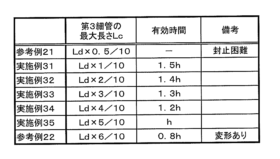
この評価結果から、実施例35を基準として、実施例31~34は有効時間が長く、寿命が長くなっていることがわかる。一方、参考例22は、実施例35よりも有効時間が短くなっている。これは、点灯中に、貫通孔16又は貫通孔72の封止部が最冷点になり、封止部の腐食が進行したものと考えられる。なお、参考例21は、貫通孔に対する封止が困難であり、その結果、寿命試験の初期段階でリークが発生した。
このように、第3細管70の最大長さLcを、基点88から第1細管14aの端部までの軸線n1に沿った長さLdの1/10~5/10とすることが好ましいことがわかる。
[第5実施例]
実施例1と同様の構成を有する実施例41~43、参考例21及び22、並びに、実施例2と同様の構成を有する実施例44~46、参考例23及び24について、図3又は図10に示す位置Paを位置Pbに対して変化させた場合に、貫通孔16又は第3細管70及び貫通孔72が光透過に与える影響を確認した。
実施例1と同様の構成を有する実施例41~43、参考例21及び22、並びに、実施例2と同様の構成を有する実施例44~46、参考例23及び24について、図3又は図10に示す位置Paを位置Pbに対して変化させた場合に、貫通孔16又は第3細管70及び貫通孔72が光透過に与える影響を確認した。
(実施例41)
上述した実施例1と同様にして10個の実施例41に係る焼結体を作製した。図3に示すように、発光部12内における貫通孔16の開口のうち、第1細管14aの軸線n1から最も遠い地点35から軸線n1に垂線Lnを引いて形成される軸線n1上の位置をPa、軸線n1上の第1電極26Aの先端の位置をPbとし、位置Pbを基準に第1細管14aへ向かう方向を正方向、第2細管14bへ向かう方向を負方向としたとき、位置Paが位置Pbと同じになるように貫通孔16を形成した点以外は、実施例1に係る焼結体と同じである。
上述した実施例1と同様にして10個の実施例41に係る焼結体を作製した。図3に示すように、発光部12内における貫通孔16の開口のうち、第1細管14aの軸線n1から最も遠い地点35から軸線n1に垂線Lnを引いて形成される軸線n1上の位置をPa、軸線n1上の第1電極26Aの先端の位置をPbとし、位置Pbを基準に第1細管14aへ向かう方向を正方向、第2細管14bへ向かう方向を負方向としたとき、位置Paが位置Pbと同じになるように貫通孔16を形成した点以外は、実施例1に係る焼結体と同じである。
(実施例42)
上述した実施例1と同様にして10個の実施例42に係る焼結体を作製した。実施例1と同様に、位置Paが位置Pbから正方向に0.5mmとなるように貫通孔16を形成した。
上述した実施例1と同様にして10個の実施例42に係る焼結体を作製した。実施例1と同様に、位置Paが位置Pbから正方向に0.5mmとなるように貫通孔16を形成した。
(実施例43)
上述した実施例1と同様にして10個の実施例43に係る焼結体を作製した。位置Paが位置Pbから正方向に2mmとなるように貫通孔16を形成した点以外は、実施例1に係る焼結体と同じである。
上述した実施例1と同様にして10個の実施例43に係る焼結体を作製した。位置Paが位置Pbから正方向に2mmとなるように貫通孔16を形成した点以外は、実施例1に係る焼結体と同じである。
(参考例21)
上述した実施例1と同様にして10個の参考例21に係る焼結体を作製した。位置Paが位置Pbから負方向に0.5mmとなるように貫通孔16を形成した点以外は、実施例1に係る焼結体と同じである。
上述した実施例1と同様にして10個の参考例21に係る焼結体を作製した。位置Paが位置Pbから負方向に0.5mmとなるように貫通孔16を形成した点以外は、実施例1に係る焼結体と同じである。
(参考例22)
上述した実施例1と同様にして10個の参考例22に係る焼結体を作製した。位置Paが位置Pbから負方向に2mmとなるように貫通孔16を形成した点以外は、実施例1に係る焼結体と同じである。
上述した実施例1と同様にして10個の参考例22に係る焼結体を作製した。位置Paが位置Pbから負方向に2mmとなるように貫通孔16を形成した点以外は、実施例1に係る焼結体と同じである。
(実施例44)
上述した実施例2と同様にして10個の実施例44に係る焼結体を作製した。図10に示すように、位置Paが位置Pbと同じになるように第3細管70及び貫通孔72を形成した点以外は、実施例2に係る焼結体と同じである。
上述した実施例2と同様にして10個の実施例44に係る焼結体を作製した。図10に示すように、位置Paが位置Pbと同じになるように第3細管70及び貫通孔72を形成した点以外は、実施例2に係る焼結体と同じである。
(実施例45)
上述した実施例2と同様にして10個の実施例45に係る焼結体を作製した。実施例2と同様に、位置Paが位置Pbから正方向に0.5mmとなるように、第3細管70及び貫通孔72を形成した。
上述した実施例2と同様にして10個の実施例45に係る焼結体を作製した。実施例2と同様に、位置Paが位置Pbから正方向に0.5mmとなるように、第3細管70及び貫通孔72を形成した。
(実施例46)
上述した実施例2と同様にして10個の実施例46に係る焼結体を作製した。位置Paが位置Pbから正方向に2mmとなるように第3細管70及び貫通孔72を形成した点以外は、実施例2に係る焼結体と同じである。
上述した実施例2と同様にして10個の実施例46に係る焼結体を作製した。位置Paが位置Pbから正方向に2mmとなるように第3細管70及び貫通孔72を形成した点以外は、実施例2に係る焼結体と同じである。
(参考例23)
上述した実施例2と同様にして10個の参考例23に係る焼結体を作製した。位置Paが位置Pbから負方向に0.5mmとなるように第3細管70及び貫通孔72を形成した点以外は、実施例2に係る焼結体と同じである。
上述した実施例2と同様にして10個の参考例23に係る焼結体を作製した。位置Paが位置Pbから負方向に0.5mmとなるように第3細管70及び貫通孔72を形成した点以外は、実施例2に係る焼結体と同じである。
(参考例24)
上述した実施例2と同様にして10個の参考例24に係る焼結体を作製した。位置Paが位置Pbから負方向に2mmとなるように第3細管70及び貫通孔72を形成した点以外は、実施例2に係る焼結体と同じである。
上述した実施例2と同様にして10個の参考例24に係る焼結体を作製した。位置Paが位置Pbから負方向に2mmとなるように第3細管70及び貫通孔72を形成した点以外は、実施例2に係る焼結体と同じである。
<評価>
評価は以下のように行った。すなわち、得られた焼結体を用いてそれぞれ発光管を作製し、各発光管について、実際の明るさを測定し、その測定値が設計上の明るさ(設計値)に対してどの程度低下しているかを確認し、測定値が設計値の99%以上であれば「A」、測定値が設計値の98%以上99%未満であれば「B」、測定値が設計値の97%以上98%未満であれば「C」、測定値が設計値の97%未満であれば「D」と判定した。
評価は以下のように行った。すなわち、得られた焼結体を用いてそれぞれ発光管を作製し、各発光管について、実際の明るさを測定し、その測定値が設計上の明るさ(設計値)に対してどの程度低下しているかを確認し、測定値が設計値の99%以上であれば「A」、測定値が設計値の98%以上99%未満であれば「B」、測定値が設計値の97%以上98%未満であれば「C」、測定値が設計値の97%未満であれば「D」と判定した。
(評価結果)
評価結果を表4に示す。
評価結果を表4に示す。

この評価結果から、実施例41~46は、いずれも発光部12への貫通孔16(又は第3細管70及び貫通孔72)の形成による光透過の影響はほとんどないことがわかった。従って、貫通孔16(又は第3細管70及び貫通孔72)を、発光部12のうち、第1細管14aに封止される第1電極26Aの端部に対応した位置よりも第1細管14a寄りの位置、より好ましくは第1電極26Aの端部に対応した位置よりも0.5mm以上第1細管14a寄りの位置に形成することが好ましいことがわかる。
なお、本発明に係るセラミックチューブ及びその製造方法は、上述の実施の形態に限らず、本発明の要旨を逸脱することなく、種々の構成を採り得ることはもちろんである。
Claims (14)
- 内部において発光が行われる発光部(12)と、該発光部(12)の両側にそれぞれ一体に形成された電極封止用の第1細管(14a)及び第2細管(14b)とを有する高輝度放電灯用のセラミックチューブにおいて、
前記発光部(12)のうち、前記第1細管(14a)寄りの位置に、該発光部(12)の内部から前記発光部(12)の外部に向かう方向が前記第1細管(14a)の延在方向と同じとされた貫通孔(16)を有することを特徴とするセラミックチューブ。 - 請求項1記載のセラミックチューブにおいて、
前記貫通孔(16)の軸線(m1)と、前記第1細管(14a)の軸線(n1)とが平行であることを特徴とするセラミックチューブ。 - 請求項1記載のセラミックチューブにおいて、
前記貫通孔(16)は、前記発光部(12)のうち、前記第1細管(14a)に封止される電極(26A)の端部に対応した位置(Pb)よりも前記第1細管(14a)寄りの位置に形成されていることを特徴とするセラミックチューブ。 - 請求項1記載のセラミックチューブにおいて、
前記貫通孔(16)は、前記発光部(12)のうち、該貫通孔(16)の軸線(m1)と前記第1細管(14a)の軸線(n1)との距離(La)が、前記第1細管(14a)の外径(Da)の0.55倍以上の位置に形成されていることを特徴とするセラミックチューブ。 - 請求項1~4のいずれか1項に記載のセラミックチューブにおいて、
前記発光部(12)は、放電領域(34)に対応する部分から前記第1細管(14a)に向かう部分、または、前記放電領域(34)に対応する部分から前記第2細管(14b)に向かう部分のいずれか一方が湾曲面とされており、その湾曲面に前記貫通孔(16)を有することを特徴とするセラミックチューブ。 - 内部において発光が行われる発光部(12)と、該発光部(12)の両側にそれぞれ一体に形成された電極封止用の第1細管(14a)及び第2細管(14b)とを有する高輝度放電灯用のセラミックチューブにおいて、
前記発光部(12)のうち、前記第1細管(14a)寄りの位置に、突出方向が前記第1細管(14a)の延在方向と同じとされた第3細管(70)を有し、
前記第3細管(70)の先端から前記発光部(12)の内方にかけて貫通する孔(72)を有することを特徴とするセラミックチューブ。 - 請求項6記載のセラミックチューブにおいて、
前記第3細管(70)の軸線(m3)と、前記第1細管(14a)の軸線(n1)とが平行であることを特徴とするセラミックチューブ。 - 請求項6記載のセラミックチューブにおいて、
前記第3細管(70)は、前記発光部(12)のうち、前記第1細管(14a)に封止される電極(26A)の端部に対応した位置(Pb)よりも前記第1細管(14a)寄りの位置に形成されていることを特徴とするセラミックチューブ。 - 請求項6記載のセラミックチューブにおいて、
前記第3細管(70)は、前記発光部(12)のうち、該第3細管(70)の軸線(m3)と前記第1細管(14a)の軸線(n1)との距離(Lb)が、前記第1細管(14a)の外径(Da)の0.55倍以上の位置に形成されていることを特徴とするセラミックチューブ。 - 請求項6記載のセラミックチューブにおいて、
前記発光部(12)の内面を前記第3細管(70)の軸線(m3)を含む面で切断した輪郭線(80)と、前記軸線(m3)との関係をみたとき、
前記輪郭線(80)における前記輪郭線(80)と前記軸線(m3)との交点(82)での接線(84)の方向と前記軸線(m3)とのなす角(θ)が30°以上であることを特徴とするセラミックチューブ。 - 請求項6記載のセラミックチューブにおいて、
前記第3細管(70)の軸線(m3)に沿った最大長さ(Lc)の基準となる点を基点(88)としたとき、
前記第3細管(70)の最大長さ(Lc)は、前記基点(88)から前記第1細管(14a)の端部までの前記第1細管(14a)の軸線(n1)に沿った長さ(Ld)の1/10~5/10であることを特徴とするセラミックチューブ。 - 請求項6~11のいずれか1項に記載のセラミックチューブにおいて、
前記発光部(12)は、放電領域(34)に対応する部分から前記第1細管(14a)に向かう部分、または、前記放電領域(34)に対応する部分から前記第2細管(14b)に向かう部分のいずれか一方が湾曲面とされており、その湾曲面に前記第3細管(70)を有することを特徴とするセラミックチューブ。 - 複数のセラミック成形体を接合して1つの高輝度放電灯用のセラミックチューブを作製するセラミックチューブの製造方法において、
第1湾曲部(18a)と第1円筒部(20a)とを一体に有し、前記第1湾曲部(18a)に前記第1円筒部(20a)の軸線方向に沿った貫通孔(16)を有する第1セラミック成形体(22A)と、第2湾曲部(18b)と第2円筒部(20b)とを一体に有する第2セラミック成形体(22B)とを作製する成形体作製工程と、
前記第1セラミック成形体(22A)の前記第1湾曲部(18a)の端面(56a)と、前記第2セラミック成形体(22B)の前記第2湾曲部(18b)の端面(56b)とを接合して接合体(58A)を作製する成形体接合工程とを有し、
前記第1セラミック成形体(22A)の前記第1円筒部(20a)の軸線(n2)と前記貫通孔(16)の軸線(m2)とが平行であることを特徴とするセラミックチューブの製造方法。 - 複数のセラミック成形体を接合して1つの高輝度放電灯用のセラミックチューブを作製するセラミックチューブの製造方法において、
第1湾曲部(18a)と第1円筒部(20a)とを一体に有し、且つ、前記第1湾曲部(18a)に前記第1円筒部(20a)の軸線方向に沿った細管(90)を有し、前記細管(90)の先端から前記第1湾曲部(18a)内にかけて貫通する孔(92)を有する第1セラミック成形体(22A)と、第2湾曲部(18b)と第2円筒部(20b)とを一体に有する第2セラミック成形体(22B)とを作製する成形体作製工程と、
前記第1セラミック成形体(22A)の前記第1湾曲部(18a)の端面(56a)と、前記第2セラミック成形体(22B)の前記第2湾曲部(18b)の端面(56b)とを接合して接合体(58B)を作製する成形体接合工程とを有し、
前記第1セラミック成形体(22A)の前記第1円筒部(18a)の軸線(n2)と前記細管(90)及び前記孔(92)の軸線(m4)とが平行であることを特徴とするセラミックチューブの製造方法。
Priority Applications (3)
| Application Number | Priority Date | Filing Date | Title |
|---|---|---|---|
| CN2011800481701A CN103155092A (zh) | 2010-10-08 | 2011-09-27 | 陶瓷管及其制造方法 |
| EP11830531.7A EP2626889A4 (en) | 2010-10-08 | 2011-09-27 | CERAMIC TUBES AND MANUFACTURING METHOD THEREFOR |
| JP2012537647A JPWO2012046598A1 (ja) | 2010-10-08 | 2011-09-27 | セラミックチューブ及びその製造方法 |
Applications Claiming Priority (2)
| Application Number | Priority Date | Filing Date | Title |
|---|---|---|---|
| JP2010228550 | 2010-10-08 | ||
| JP2010-228550 | 2010-10-08 |
Publications (1)
| Publication Number | Publication Date |
|---|---|
| WO2012046598A1 true WO2012046598A1 (ja) | 2012-04-12 |
Family
ID=45927593
Family Applications (1)
| Application Number | Title | Priority Date | Filing Date |
|---|---|---|---|
| PCT/JP2011/072113 Ceased WO2012046598A1 (ja) | 2010-10-08 | 2011-09-27 | セラミックチューブ及びその製造方法 |
Country Status (4)
| Country | Link |
|---|---|
| EP (1) | EP2626889A4 (ja) |
| JP (1) | JPWO2012046598A1 (ja) |
| CN (1) | CN103155092A (ja) |
| WO (1) | WO2012046598A1 (ja) |
Citations (18)
| Publication number | Priority date | Publication date | Assignee | Title |
|---|---|---|---|---|
| JPS63143738A (ja) | 1986-12-05 | 1988-06-16 | Toshiba Corp | セラミツク放電灯 |
| JPH04163828A (ja) * | 1990-10-26 | 1992-06-09 | Nec Kagoshima Ltd | 蛍光表示管用カバーガラスの製造方法 |
| JPH05334962A (ja) | 1992-05-29 | 1993-12-17 | Toto Ltd | 金属蒸気放電灯の製造方法 |
| JPH0721990A (ja) | 1993-02-05 | 1995-01-24 | Ngk Insulators Ltd | 高圧放電ランプ用セラミック放電管及びその製造方法、並びにそれに用いられるシール材料 |
| JPH0737501A (ja) * | 1993-07-22 | 1995-02-07 | Iwasaki Electric Co Ltd | メタルハライドランプの製造方法 |
| JPH0855606A (ja) | 1994-08-15 | 1996-02-27 | Toto Ltd | 金属蒸気発光管 |
| JPH10340705A (ja) * | 1997-06-06 | 1998-12-22 | Matsushita Electron Corp | 放電ランプ、この放電ランプの製造方法、この放電ランプを用いたランプユニット、およびこのランプユニットを用いた光学システム |
| JPH1167155A (ja) * | 1997-06-27 | 1999-03-09 | Patent Treuhand Ges Elektr Gluehlamp Mbh | 高圧放電ランプ |
| JP2001035445A (ja) * | 1992-07-09 | 2001-02-09 | Toto Ltd | 発光管の封止部構造 |
| WO2002085590A1 (en) | 2001-04-17 | 2002-10-31 | Ngk Insulators, Ltd. | Method of manufacturing molded body, slurry for molding, core for molding, method of manufacturing core for molding, hollow ceramic molded body, and light emitting container |
| JP2002334653A (ja) * | 2001-02-09 | 2002-11-22 | Matsushita Electric Ind Co Ltd | 発光管の製造方法及びそれに用いられる中子 |
| JP2003346723A (ja) * | 2002-05-30 | 2003-12-05 | Toshiba Lighting & Technology Corp | 放電ランプおよびその製造方法 |
| US20060001346A1 (en) | 2004-06-30 | 2006-01-05 | Vartuli James S | System and method for design of projector lamp |
| JP2006092865A (ja) * | 2004-09-22 | 2006-04-06 | Ushio Inc | ショートアーク型放電ランプ |
| JP2008044344A (ja) | 2006-03-24 | 2008-02-28 | Ngk Insulators Ltd | 焼結体、発光管及びその製造方法 |
| JP2009530127A (ja) | 2006-03-24 | 2009-08-27 | 日本碍子株式会社 | 焼結体の製造方法および焼結体 |
| JP2010514127A (ja) | 2006-12-20 | 2010-04-30 | コーニンクレッカ フィリップス エレクトロニクス エヌ ヴィ | セラミックメタルハライドランプのためのセラミックバーナ |
| JP2010514125A (ja) | 2006-12-20 | 2010-04-30 | コーニンクレッカ フィリップス エレクトロニクス エヌ ヴィ | メタルハライドランプ及びこのようなランプのためのセラミックバーナ |
Family Cites Families (1)
| Publication number | Priority date | Publication date | Assignee | Title |
|---|---|---|---|---|
| CN101410348B (zh) * | 2006-03-24 | 2013-01-09 | 日本碍子株式会社 | 烧结体、发光管及其制造方法 |
-
2011
- 2011-09-27 EP EP11830531.7A patent/EP2626889A4/en not_active Withdrawn
- 2011-09-27 WO PCT/JP2011/072113 patent/WO2012046598A1/ja not_active Ceased
- 2011-09-27 JP JP2012537647A patent/JPWO2012046598A1/ja not_active Withdrawn
- 2011-09-27 CN CN2011800481701A patent/CN103155092A/zh active Pending
Patent Citations (18)
| Publication number | Priority date | Publication date | Assignee | Title |
|---|---|---|---|---|
| JPS63143738A (ja) | 1986-12-05 | 1988-06-16 | Toshiba Corp | セラミツク放電灯 |
| JPH04163828A (ja) * | 1990-10-26 | 1992-06-09 | Nec Kagoshima Ltd | 蛍光表示管用カバーガラスの製造方法 |
| JPH05334962A (ja) | 1992-05-29 | 1993-12-17 | Toto Ltd | 金属蒸気放電灯の製造方法 |
| JP2001035445A (ja) * | 1992-07-09 | 2001-02-09 | Toto Ltd | 発光管の封止部構造 |
| JPH0721990A (ja) | 1993-02-05 | 1995-01-24 | Ngk Insulators Ltd | 高圧放電ランプ用セラミック放電管及びその製造方法、並びにそれに用いられるシール材料 |
| JPH0737501A (ja) * | 1993-07-22 | 1995-02-07 | Iwasaki Electric Co Ltd | メタルハライドランプの製造方法 |
| JPH0855606A (ja) | 1994-08-15 | 1996-02-27 | Toto Ltd | 金属蒸気発光管 |
| JPH10340705A (ja) * | 1997-06-06 | 1998-12-22 | Matsushita Electron Corp | 放電ランプ、この放電ランプの製造方法、この放電ランプを用いたランプユニット、およびこのランプユニットを用いた光学システム |
| JPH1167155A (ja) * | 1997-06-27 | 1999-03-09 | Patent Treuhand Ges Elektr Gluehlamp Mbh | 高圧放電ランプ |
| JP2002334653A (ja) * | 2001-02-09 | 2002-11-22 | Matsushita Electric Ind Co Ltd | 発光管の製造方法及びそれに用いられる中子 |
| WO2002085590A1 (en) | 2001-04-17 | 2002-10-31 | Ngk Insulators, Ltd. | Method of manufacturing molded body, slurry for molding, core for molding, method of manufacturing core for molding, hollow ceramic molded body, and light emitting container |
| JP2003346723A (ja) * | 2002-05-30 | 2003-12-05 | Toshiba Lighting & Technology Corp | 放電ランプおよびその製造方法 |
| US20060001346A1 (en) | 2004-06-30 | 2006-01-05 | Vartuli James S | System and method for design of projector lamp |
| JP2006092865A (ja) * | 2004-09-22 | 2006-04-06 | Ushio Inc | ショートアーク型放電ランプ |
| JP2008044344A (ja) | 2006-03-24 | 2008-02-28 | Ngk Insulators Ltd | 焼結体、発光管及びその製造方法 |
| JP2009530127A (ja) | 2006-03-24 | 2009-08-27 | 日本碍子株式会社 | 焼結体の製造方法および焼結体 |
| JP2010514127A (ja) | 2006-12-20 | 2010-04-30 | コーニンクレッカ フィリップス エレクトロニクス エヌ ヴィ | セラミックメタルハライドランプのためのセラミックバーナ |
| JP2010514125A (ja) | 2006-12-20 | 2010-04-30 | コーニンクレッカ フィリップス エレクトロニクス エヌ ヴィ | メタルハライドランプ及びこのようなランプのためのセラミックバーナ |
Also Published As
| Publication number | Publication date |
|---|---|
| JPWO2012046598A1 (ja) | 2014-02-24 |
| EP2626889A4 (en) | 2014-05-28 |
| EP2626889A1 (en) | 2013-08-14 |
| CN103155092A (zh) | 2013-06-12 |
Similar Documents
| Publication | Publication Date | Title |
|---|---|---|
| KR100538392B1 (ko) | 세라믹밀봉장치,이러한밀봉장치를구비한램프,및이러한장치의제조방법 | |
| EP1568066B1 (en) | High-pressure discharge lamp, and method of manufacture thereof | |
| CN1950925B (zh) | 具有优化形状的陶瓷金属卤化物灯具 | |
| JP5197975B2 (ja) | 焼結体、発光管及びその製造方法 | |
| US6346495B1 (en) | Die pressing arctube bodies | |
| US6224449B1 (en) | Method of forming lead-in seal in high pressure discharge lamps | |
| CN1278373C (zh) | 高压放电灯 | |
| US8420932B2 (en) | Ceramic tube for high-intensity discharge lamp and method of producing the same | |
| JPWO2012046598A1 (ja) | セラミックチューブ及びその製造方法 | |
| US6819047B2 (en) | High pressure discharge lamps, and assemblies and discharge vessels therefor | |
| EP2000447A2 (en) | Sintered body, light emitting tube and process for manufacturing the same | |
| WO2012046597A1 (ja) | セラミックチューブの製造方法及びセラミックチューブ | |
| JP3776636B2 (ja) | 高圧放電灯 | |
| JP2012119129A (ja) | 発光管及びその製造方法 | |
| CN101410348A (zh) | 烧结体、发光管及其制造方法 | |
| CN1607634A (zh) | 用于电灯引线元件的合金和电灯的电极结构 | |
| US20060222878A1 (en) | Composite bodies | |
| US6592808B1 (en) | Cermet sintering of ceramic discharge chambers | |
| JP4859210B2 (ja) | 接合焼結体の製造方法および接合焼結体 | |
| JP2006160595A (ja) | 透光性セラミックス、その製造方法および発光容器 | |
| JP5084463B2 (ja) | 電極構造体の製造方法 | |
| CN1723533A (zh) | 金属卤灯 | |
| CN1922714A (zh) | 高压钠灯 | |
| CN1794415A (zh) | 高压放电灯 | |
| WO2010014440A1 (en) | Ceramic discharge vessel and method of making same |
Legal Events
| Date | Code | Title | Description |
|---|---|---|---|
| WWE | Wipo information: entry into national phase |
Ref document number: 201180048170.1 Country of ref document: CN |
|
| 121 | Ep: the epo has been informed by wipo that ep was designated in this application |
Ref document number: 11830531 Country of ref document: EP Kind code of ref document: A1 |
|
| WWE | Wipo information: entry into national phase |
Ref document number: 2012537647 Country of ref document: JP |
|
| WWE | Wipo information: entry into national phase |
Ref document number: 2011830531 Country of ref document: EP |
|
| NENP | Non-entry into the national phase |
Ref country code: DE |