WO2012046733A1 - 車両用燃料タンク - Google Patents
車両用燃料タンク Download PDFInfo
- Publication number
- WO2012046733A1 WO2012046733A1 PCT/JP2011/072878 JP2011072878W WO2012046733A1 WO 2012046733 A1 WO2012046733 A1 WO 2012046733A1 JP 2011072878 W JP2011072878 W JP 2011072878W WO 2012046733 A1 WO2012046733 A1 WO 2012046733A1
- Authority
- WO
- WIPO (PCT)
- Prior art keywords
- tank
- bead
- lower tank
- auxiliary
- width
- Prior art date
- Legal status (The legal status is an assumption and is not a legal conclusion. Google has not performed a legal analysis and makes no representation as to the accuracy of the status listed.)
- Ceased
Links
Images


Classifications
-
- B—PERFORMING OPERATIONS; TRANSPORTING
- B60—VEHICLES IN GENERAL
- B60K—ARRANGEMENT OR MOUNTING OF PROPULSION UNITS OR OF TRANSMISSIONS IN VEHICLES; ARRANGEMENT OR MOUNTING OF PLURAL DIVERSE PRIME-MOVERS IN VEHICLES; AUXILIARY DRIVES FOR VEHICLES; INSTRUMENTATION OR DASHBOARDS FOR VEHICLES; ARRANGEMENTS IN CONNECTION WITH COOLING, AIR INTAKE, GAS EXHAUST OR FUEL SUPPLY OF PROPULSION UNITS IN VEHICLES
- B60K15/00—Arrangement in connection with fuel supply of combustion engines or other fuel consuming energy converters, e.g. fuel cells; Mounting or construction of fuel tanks
- B60K15/03—Fuel tanks
- B60K15/073—Tank construction specially adapted to the vehicle
-
- B—PERFORMING OPERATIONS; TRANSPORTING
- B60—VEHICLES IN GENERAL
- B60K—ARRANGEMENT OR MOUNTING OF PROPULSION UNITS OR OF TRANSMISSIONS IN VEHICLES; ARRANGEMENT OR MOUNTING OF PLURAL DIVERSE PRIME-MOVERS IN VEHICLES; AUXILIARY DRIVES FOR VEHICLES; INSTRUMENTATION OR DASHBOARDS FOR VEHICLES; ARRANGEMENTS IN CONNECTION WITH COOLING, AIR INTAKE, GAS EXHAUST OR FUEL SUPPLY OF PROPULSION UNITS IN VEHICLES
- B60K15/00—Arrangement in connection with fuel supply of combustion engines or other fuel consuming energy converters, e.g. fuel cells; Mounting or construction of fuel tanks
- B60K15/03—Fuel tanks
- B60K2015/03032—Manufacturing of fuel tanks
-
- B—PERFORMING OPERATIONS; TRANSPORTING
- B60—VEHICLES IN GENERAL
- B60K—ARRANGEMENT OR MOUNTING OF PROPULSION UNITS OR OF TRANSMISSIONS IN VEHICLES; ARRANGEMENT OR MOUNTING OF PLURAL DIVERSE PRIME-MOVERS IN VEHICLES; AUXILIARY DRIVES FOR VEHICLES; INSTRUMENTATION OR DASHBOARDS FOR VEHICLES; ARRANGEMENTS IN CONNECTION WITH COOLING, AIR INTAKE, GAS EXHAUST OR FUEL SUPPLY OF PROPULSION UNITS IN VEHICLES
- B60K15/00—Arrangement in connection with fuel supply of combustion engines or other fuel consuming energy converters, e.g. fuel cells; Mounting or construction of fuel tanks
- B60K15/03—Fuel tanks
- B60K2015/03105—Fuel tanks with supplementary interior tanks inside the fuel tank
-
- B—PERFORMING OPERATIONS; TRANSPORTING
- B60—VEHICLES IN GENERAL
- B60K—ARRANGEMENT OR MOUNTING OF PROPULSION UNITS OR OF TRANSMISSIONS IN VEHICLES; ARRANGEMENT OR MOUNTING OF PLURAL DIVERSE PRIME-MOVERS IN VEHICLES; AUXILIARY DRIVES FOR VEHICLES; INSTRUMENTATION OR DASHBOARDS FOR VEHICLES; ARRANGEMENTS IN CONNECTION WITH COOLING, AIR INTAKE, GAS EXHAUST OR FUEL SUPPLY OF PROPULSION UNITS IN VEHICLES
- B60K15/00—Arrangement in connection with fuel supply of combustion engines or other fuel consuming energy converters, e.g. fuel cells; Mounting or construction of fuel tanks
- B60K15/03—Fuel tanks
- B60K2015/03111—Swirl pots
-
- B—PERFORMING OPERATIONS; TRANSPORTING
- B60—VEHICLES IN GENERAL
- B60K—ARRANGEMENT OR MOUNTING OF PROPULSION UNITS OR OF TRANSMISSIONS IN VEHICLES; ARRANGEMENT OR MOUNTING OF PLURAL DIVERSE PRIME-MOVERS IN VEHICLES; AUXILIARY DRIVES FOR VEHICLES; INSTRUMENTATION OR DASHBOARDS FOR VEHICLES; ARRANGEMENTS IN CONNECTION WITH COOLING, AIR INTAKE, GAS EXHAUST OR FUEL SUPPLY OF PROPULSION UNITS IN VEHICLES
- B60K15/00—Arrangement in connection with fuel supply of combustion engines or other fuel consuming energy converters, e.g. fuel cells; Mounting or construction of fuel tanks
- B60K15/03—Fuel tanks
- B60K2015/03328—Arrangements or special measures related to fuel tanks or fuel handling
- B60K2015/03453—Arrangements or special measures related to fuel tanks or fuel handling for fixing or mounting parts of the fuel tank together
- B60K2015/0346—Arrangements or special measures related to fuel tanks or fuel handling for fixing or mounting parts of the fuel tank together by welding
Definitions
- the present invention relates to a vehicle fuel tank provided in a vehicle.
- Engine driven vehicles are provided with fuel tanks that store fuel such as gasoline.
- fuel tanks that store fuel such as gasoline.
- the upper tank and the lower tank are joined by welding, and the fuel is stored in a closed space formed by the upper tank and the lower tank.
- An auxiliary tank is generally provided on the inner bottom surface of the lower tank of the fuel tank, so that even when the vehicle is tilted, the specified liquid level is always maintained to prevent fuel suction failure and fuel can be stably supplied to the engine. It is configured.
- the auxiliary tank is fixed to the lower tank by spot welding with the outer bottom face facing the inner bottom face of the lower tank.
- Patent Document 1 discloses a technique for improving bending rigidity by attaching a sub-tank to a bottom surface of a tank via a plate-like support in order to reduce stress concentration in a welded portion.
- Patent Document 2 discloses a vehicular fuel tank in which the position of a spot welding portion that fixes an auxiliary tank and a lower tank is changed, and a concave beat and a convex beat are linearly provided on the bottom of the lower tank.
- Patent Document 3 discloses a technique for reinforcing a stay by providing a stay in order to prevent separation between the auxiliary tank and the tank bottom.
- Patent Document 4 discloses a vehicular fuel tank provided with a beat extending in a different direction between a central portion in the longitudinal direction of the tank main body and both side portions of the auxiliary tank installation portion on the bottom surface of the tank main body. ing.
- the present invention has been made in view of the above problems, and an object of the present invention is to increase the rigidity of the tank and to fatigue the welded portion that fastens the auxiliary tank and the lower tank due to vertical vibration during traveling. It is an object of the present invention to provide a new and improved fuel tank capable of preventing destruction.
- an upper tank and a lower tank are joined to each other to form a closed body in which fuel is accommodated, and a spot welded to the bottom portion of the lower tank
- the spot welding is set in a plurality of rows along the longitudinal direction of the lower tank at a distance in the width direction of the auxiliary tank, and in the longitudinal direction at the bottom surface of the lower tank.
- at least one bead positioned between the rows of the spot welds extending continuously, and the lower surface of the auxiliary tank does not have a portion that does not contact the bottom surface of the lower tank except the bead.
- a fuel tank for a vehicle is provided.
- the bottom portion of the lower tank has the second direction (longitudinal direction) orthogonal to the first direction on the approximate center line of the length in the first direction (width direction) of the auxiliary tank.
- the length of the bead is formed to be 80% or more of the flat part length of the bottom part of the lower tank in the longitudinal direction. Thereby, the rigidity of the vehicle fuel tank can be sufficiently maintained.
- the beads may be formed continuously from the bottom part of the lower tank to the side wall part.
- the plurality of rows of spot welding may be arranged symmetrically with respect to the beads formed on the approximate center line in the width direction of the auxiliary tank.
- the width of the bead may be formed to a length of 50% or more of the interval between adjacent spot welds across the bead. Thereby, the rigidity of the vehicle fuel tank can be sufficiently maintained.
- Another bead may be formed in a flat portion between the end surface in the width direction of the auxiliary tank and the side wall of the lower tank along the longitudinal direction of the bottom surface of the lower tank.
- the bead may be formed in a meandering bead meandering in the width direction or a width-changing bead in which the width is changed.
- the tank body and the auxiliary tank may be made of at least one of a surface-treated steel plate, stainless steel, or an aluminum alloy, and the lower tank and the auxiliary tank may be formed of the same material.
- a fuel tank capable of increasing the rigidity of the tank and preventing fatigue fracture of the welded portion that fastens the auxiliary tank and the lower tank due to vertical vibration during traveling. it can.
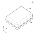
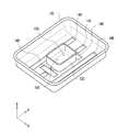
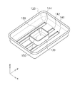
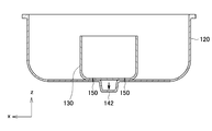
- FIG. 1 is a perspective view showing an appearance of a vehicle fuel tank according to a first embodiment of the present invention.
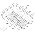
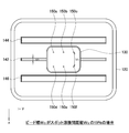
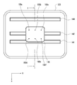
- FIG. 2 is a perspective view showing the inside of the lower tank of the vehicle fuel tank according to the first embodiment of the present invention.
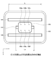
- FIG. 3 is a plan view of FIG.
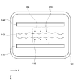
- FIG. 4 is an explanatory diagram showing the secondary panel vibration mode when the bead length L B is the flat portion length L.
- FIG. 5 is an explanatory diagram showing the secondary panel vibration mode when the bead length L B is the flat portion length L.
- FIG. Figure 6 is a plan view showing the shape of a lower tank when the bead shown in Figure 3 the length L B to 48% of the flat portion length L.
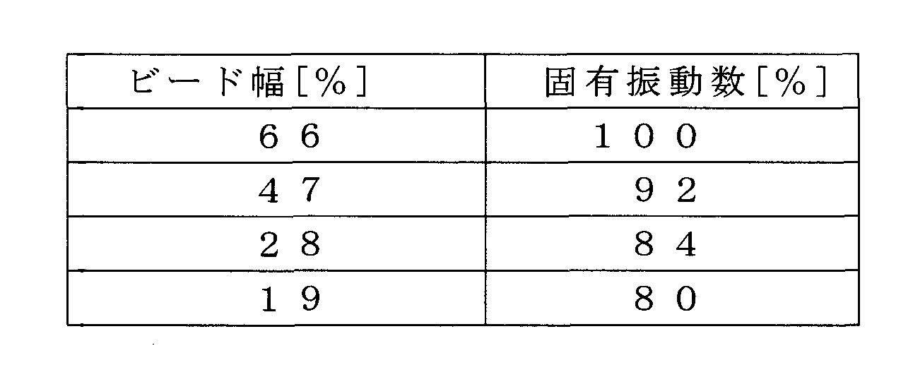
- FIG. 7 is an explanatory view showing the shape of the lower tank when the bead width W B of the bead is 66% of the length of the spot welding distance W S.
- Figure 10 is an explanatory view showing the shape of the lower tank when the bead width W B of the bead is 19% of the length of the spot welding distance W S.
- Figure 11 is an explanatory view showing the shape of a lower tank when forming the Sabubido auxiliary tank side of Sabubido the deployable width W A.
- FIG. 12 is an explanatory view showing the shape of a lower tank when forming the Sabubido the side surface of the lower tank of Sabubido the deployable width W A.
- FIG. 13 is an explanatory diagram showing the shape of the lower tank when three discontinuous beads are formed on the bottom surface of the lower tank.
- FIG. 14 is an explanatory diagram showing a secondary panel vibration mode of a fuel tank having a lower tank in which the discontinuous beads of FIG. 13 are formed.
- FIG. 15 is an explanatory diagram showing a secondary panel vibration mode of the fuel tank having the lower tank in which the discontinuous beads of FIG. 13 are formed.
- FIG. 16 is a perspective view showing the inside of a lower tank having another bead around the extension of the bead as a comparative example to the present invention.
- FIG. 17 is a plan view of the lower tank of FIG.
- FIG. 18 is an explanatory diagram showing a secondary panel vibration mode in a lower tank having another bead.
- FIG. 19 is an explanatory diagram showing a secondary panel vibration mode in a lower tank having another bead.
- FIG. 20 is a perspective view showing the inside of a lower tank having a portion where the lower surface of the auxiliary tank does not contact other than the beads as a comparative example to the present invention.
- 21 is a plan view of the lower tank of FIG. 22 is a cross-sectional view taken along the line II of FIG.
- FIG. 23 is an explanatory diagram showing a secondary panel vibration mode in the lower tank having a portion where the lower surface of the auxiliary tank does not contact other than the beads.
- FIG. 20 is a perspective view showing the inside of a lower tank having a portion where the lower surface of the auxiliary tank does not contact other than the beads as a comparative example to the present invention.
- 21 is a plan view
- FIG. 24 is an explanatory diagram showing a secondary panel vibration mode in the lower tank having a portion where the lower surface of the auxiliary tank does not contact other than the beads.
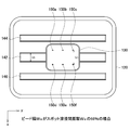
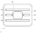
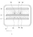
- FIG. 25 is a plan view showing one configuration of the fuel tank according to the second embodiment of the present invention.
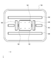
- FIG. 26 is a plan view showing another configuration of the fuel tank according to the second embodiment of the present invention.
- FIG. 27 is a cross-sectional view showing an example of the shape of the lower tank when the bead formed in the lower tank has a convex shape.
- FIG. 28 is a cross-sectional view showing an example of the shape of the lower tank when the bead formed in the lower tank has a convex shape.
- FIG. 29 is a plan view of a lower tank having meandering beads as a modification of the present invention.
- FIG. 30 is a plan view of a lower tank having a width change bead as a modification of the present invention.
- FIG. 1 is a perspective view showing an appearance of a vehicle fuel tank 100 according to the present embodiment.
- FIG. 2 is a perspective view showing the inside of the lower tank 120 of the vehicle fuel tank 100 according to the present embodiment.
- FIG. 3 is a plan view of FIG.
- the longitudinal direction of the fuel tank 100 is the vehicle traveling direction.
- the vehicle fuel tank 100 is formed by joining an upper tank 110 and a lower tank 120 as shown in FIG.
- the upper tank 110 and the lower tank 120 according to the present embodiment each have a bottom surface portion and a side wall portion, and flanges formed at the opening portions of the upper tank 110 and the lower tank 120, that is, the edge portions of the side wall portions are opposed to each other.
- the tank body is configured by joining. Thereby, the closed space which accommodates fuel can be formed.
- a joint portion between the bottom surface portion and the side wall portion is formed in an R-shaped bent portion.
- an auxiliary tank 130 is fixed to the bottom surface portion 124 of the lower tank 120.
- the auxiliary tank 130 is fixed by spot welding.
- a spot welded portion is represented as a spot weld 150.
- the lower tank 120 and the auxiliary tank 130 of the present embodiment are fixed by six spot welds 150a to 150f.
- the bottom portion 124 of the lower tank 120, the width direction (x direction) of the lower tank width W L longitudinal direction (y-direction) bead 142 consecutive seamless to the approximate center line of the length of the auxiliary tank 130 is formed.
- the lower tank 120 of the present embodiment as the center of the width of the bead 142 on the center line of the lower tank width W L is located, although the bead 142 is formed, strictly lower tank width W
- the bead 142 may not be formed on the center line of L. In this case, it is desirable that the bead 142 is formed on the center line of the lower tank width W L.
- two side beads 144 and 146 are formed on both sides of the bead 142 substantially parallel to the bead 142.
- the upper tank 110, the lower tank 120, and the auxiliary tank 130 that constitute the fuel tank 100 are formed of, for example, a surface-treated steel plate, stainless steel, aluminum alloy or the like that has been subjected to surface treatment such as plating or painting. Since the lower tank 120 and the auxiliary tank 130 are fixed by spot welding, they are formed from the same material.
- the vehicle fuel tank 100 according to this embodiment, the bottom portion 124 of the lower tank 120, to form a bead 142 extending continuously along the longitudinal direction in the approximate center line of the lower tank width W L of the auxiliary tank 130 It is characterized by that.
- a bead is provided in the lower tank 120 in order to improve the rigidity of the fuel tank 100.
- a spot welded portion that fastens the auxiliary tank and the lower tank due to vertical vibration during traveling effectively. It was not possible to prevent fatigue failure.
- the inventors of the present application have determined that in the fuel tank 100 in which the auxiliary tank 130 is attached to the bottom surface portion 124 of the lower tank 120, the secondary panel vibration mode of the bottom surface portion 124 of the lower tank 120 is different between the lower tank 120 and the auxiliary tank. It was determined that this is a factor that peels off the spot weld 150 that secures 130. That is, in the fuel tank 100 according to the present embodiment, it is important to effectively improve the rigidity (natural frequency) of the bottom surface portion 124 of the lower tank 120 with respect to the secondary panel vibration mode. It is necessary to form the lower tank 120.
- the shape of the bead 142 formed in the lower tank 120 of the fuel tank 100 according to the present embodiment and the shapes of the sub-beads 144 and 146 provided to further increase the rigidity of the fuel tank 100 will be described in detail. .
- [1-2. Bead shape] (A. Bead length) First, based on FIGS. 3 to 8, illustrating the length L B in the longitudinal direction of the bead 142 formed on the lower tank 120.
- the length L B of the bead 142 are desirably about 80% or more of the length of the flat portion length L of the portion R shape of the bottom portion 124 of the lower tank 120 is not formed.
- the natural frequency of the secondary panel vibration mode can be suppressed to decrease up to 10%, the rigidity of the fuel tank 100 can be sufficiently retained.
- the effect of the L B length of the bead 142 and about 80% of the length of the flat portion length L was verified by simulation using the finite element method.
- the size of the lower tank 120 was 600 mm in length, 450 mm in width, and 120 mm in height
- the size of the auxiliary tank 130 was 200 mm in length, 160 mm in width, and 90 mm in height.
- a bead 142 and sub-beads 144 and 146 are formed on the bottom surface portion 124 of the lower tank 120, and these have a width of 40 mm and a depth of 7 mm, respectively.
- the lower tank 120 and the auxiliary tank 130 are spot welds 150a to 150c provided in the longitudinal direction between the bead 142 and the sub bead 144, and spot welds provided in the longitudinal direction between the bead 142 and the sub bead 146. It is assumed that they are fixed by 150d to 150f.
- the natural frequency ( “first reference natural frequency when the length L B of the bead 142 is a flat portion length L also referred to as a number ".) was calculated length L B ratio natural frequency after the change of the bead 142 against.
- FIGS. 4 and 5 The simulation results are shown in Table 1 below and FIGS. 4 and 5, when the length L B of the bead 142 and the flat portion length L, and an explanatory view showing a second panel vibration mode.
- Figure 6 is a plan view showing the shape of the lower tank 120 when the length L B of the bead 142 to 48% of the flat portion length L. 7 and 8, when the length L B of the bead 142 to 48% of the flat portion length L, and an explanatory view showing a second panel vibration mode. 4, 5, 7, and 8, the darker the portion, the greater the amplitude of the fuel tank 100 in the vertical direction (z direction).
- the amplitudes at the spot welded portions 150a, 150c, 150d, and 150f near the side wall portion 122 of the lower tank 120 are larger than those of other portions. That is, as shown in FIG. 5, it can be seen that the lower tank 120 vibrates in a vibration mode in which the spot welds 150a, 150c, 150d and 150f are antinodes and the spot welds 150b and 150e are nodes.
- L B is defined as 80% or more of the flat portion length L.
- the length L B of the bead 142 beyond the flat portion length L of the lower tank 120 may be formed continuously to the side wall portion 122.
- Bead width W B in the x-direction of the bead 142 Bead width W B of the bead 142 formed on the lower tank 120 according to this embodiment, also referred to as a distance between the two rows of spot welds 150a ⁇ 150c and 150d ⁇ 150f adjacent to the x-direction ( "spot welding distance.” ) It is desirable that the length is about 50% or more of WS .
- the bead width W B of about 50% or more of the length of the spot welding distance W S it is possible to suppress the natural frequency of the secondary panel vibration mode to decrease of about 10%, the rigidity of the fuel tank 100 Can be held sufficiently.
- the size of the lower tank 120 was 600 mm in length, 450 mm in width, and 120 mm in height
- the size of the auxiliary tank 130 was 200 mm in length, 160 mm in width, and 90 mm in height.
- a bead 142 and sub-beads 144 and 146 are formed on the bottom surface portion 124 of the lower tank 120, and each of them has a depth of 7 mm.
- the lower tank 120 and the auxiliary tank 130 are spot welds 150a to 150c provided in the longitudinal direction between the bead 142 and the sub bead 144, and spot welds provided in the longitudinal direction between the bead 142 and the sub bead 146. It is assumed that they are fixed by 150d to 150f.
- the distance between spot welds WS was 85 mm, and the bead widths of the sub-beads 144 and 146 were 40 mm.
- the bead width W B of the bead 142 to change the ratio of spot welding distance W S
- the natural frequency when the bead width W B of the bead 142 is 66% of the length of the spot welding distance W S was calculated (also referred to as a "second reference natural frequency".) ratio natural frequency of after bead width W B changes the bead 142 against. Note that 66% of the length of the spot welding distance W S was considered the space required at the time of spot welding operations, which is the maximum value of the bead width W B of the bead 142 may take on production (see Figure 9).
- the lower tank 120 on both sides of the lower tank width W L bead 142 which is continuous seamless formed longitudinally substantially at the center line of the auxiliary tank 130, Sabubido 144 and 146 are formed.
- the sub beads 144 and 146 are formed in an auxiliary manner in order to further increase the rigidity of the lower tank 120.
- the sub-beads 144 and 146 may be formed in a flat portion (also referred to as “sub-bead arrangement width W A ”) from the end surface of the auxiliary tank 130 to the R-shaped stop of the bent portion of the lower tank 120 in the width direction of the lower tank 120.
- Sabubido 144, 146 in Sabubido placeable within the width W A may be formed on the auxiliary tank 130 side as shown in FIG. 11, be formed on the side surface side of the lower tank 120, as shown in FIG. 12 Good.
- a tank having the same shape as the lower tank 120 and the auxiliary tank 130 set in the above-described examination of the bead length is assumed, and the installation position of the sub beads 144 and 146 is changed from the end surface of the auxiliary tank 130 to the R shape of the lower tank 120.
- the change of the natural frequency when it was changed in the flat part until the stop was verified.
- the installation positions of the sub beads 144 and 146 are changed within the above range, the natural frequency changes within 10% of the first reference natural frequency, and the change in the installation position of the sub beads 144 and 146 No significant change in natural frequency was observed.
- Sabubido 144, 146 Sabubido may be formed deployable width W A is a flat portion to R shape blind bend of the lower tank 120 from the end face of the auxiliary tank 130.
- the natural frequency of the secondary panel vibration mode can be suppressed to a decrease of about 10%, and the rigidity of the fuel tank 100 can be sufficiently maintained.
- the natural frequency of the lower panel vibration mode of the lower tank 120 is about 30% compared with the natural frequency (first reference natural frequency) of the lower tank 120 shown in FIG. It turned out to be reduced.
- the bottom portion 124 of the lower tank 120 substantially at the center line of the lower tank width W L of the auxiliary tank 130, by forming a bead 142 that longitudinally continuous, to form discrete beads 147-149 It is recognized that the natural frequency of the secondary panel vibration mode can be effectively improved as compared with the case.
- sub-beads 144 and 146 are formed on both sides of a bead 142 formed in the longitudinal direction on the bottom surface portion of the auxiliary tank 130.
- a case where two beads 140 are formed on both sides of the auxiliary tank 130 along the direction perpendicular to the longitudinal direction of the bead 142 as beads in different directions is used as a comparative example. Then, the effect of the case where the bead 140 in the direction different from the longitudinal direction is formed around the longitudinal extension of the bead 142 in the model in this form was verified by simulation.
- the secondary panel vibration mode natural frequency and the first reference natural frequency were compared.
- the secondary panel vibration mode natural frequency of this model was compared with the first reference natural frequency.
- 18 and 19 show the simulation results of the secondary panel vibration mode in this model.
- the rigidity is locally reduced at the discontinuous portion where the bead 140 in the direction perpendicular to the longitudinal direction exists as a bead in a different direction, resulting in a maximum displacement position of the vibration.
- the longitudinal direction of the bead 142 If beads 140 in different directions are formed around the extension, the rigidity will decrease. Therefore, it is preferable that beads in different directions are not formed around the extension of the bead 142 in the longitudinal direction.
- sub-beads 141 and 144 are formed on both sides of a bead 142 formed in the longitudinal direction on the bottom surface portion of the auxiliary tank 130.
- a bead 142 formed in the longitudinal direction on the bottom surface portion of the auxiliary tank 130.
- the influence was verified by simulation.
- the vehicle fuel tank 100 according to the first embodiment of the present invention has been described above.
- a bead 142 that longitudinally continuous, it is not possible to locally rigidity decreases, the lower tank 120 by vertical vibration during the automatic's drive assistance It is possible to effectively prevent fatigue failure of the spot welded portion 150 that is a joint portion with the tank 130.
- the bead 142 is not formed with a bead in a different direction around the longitudinal extension of the bead 142 and does not have a portion that does not come into contact with the bottom surface of the lower tank 120 except for the bead 142 to ensure rigidity and fracture strength. It is extremely effective in achieving this.
- FIG. 25 is a plan view showing one configuration of the fuel tank 100 according to the present embodiment.
- FIG. 26 is a plan view showing another configuration of the fuel tank 100 according to the present embodiment.
- Fuel tank 100 according to this embodiment, the bottom portion 124 of the lower tank 120, the auxiliary with beads 142 continuous in the longitudinal direction is formed in a substantially center line of the lower tank width W L of the auxiliary tank 130, the lower tank 120 tank 130 Embossed portions 160a to 160d are formed by embossing between spot welded portions 150a to 150f that are fixed to each other.
- the embossed portions 160a to 160d function in the same manner as the sub beads 144 and 146 formed on the bottom surface portion 124 of the lower tank 120 of the vehicle fuel tank 100 according to the first embodiment, and in the secondary panel vibration mode of the fuel tank 100.
- An auxiliary is provided to improve the rigidity.
- a bead 142 that extends continuously in the longitudinal direction on a substantially center line in the width direction of the auxiliary tank 130, a sub-bead 144 that is adjacent to the bead 142 in the width direction, 146 is formed.
- the auxiliary tank 130 is fixed to the lower tank 120 with three spot welds 150a to 150c and 150d to 150f on both sides of the bead 142, respectively.
- four embossed portions 160a to 160d are formed between the spot welded portions 150a to 150c and 150d to 150f in the installation area of the auxiliary tank 130.
- the embossed portion 160a is formed between the spot welded portions 150a and 150b, and the embossed portion 160b is formed between the spot welded portions 150b and 150c.
- the embossed portion 160c is formed between the spot welded portions 150d and 150e, and the embossed portion 160c is formed between the spot welded portions 150e and 150f.
- the emboss width in the width direction (x direction), the emboss length in the longitudinal direction (y direction), and the emboss depth in the depth direction (z direction) can be set as appropriate. In the example shown in FIG.
- the emboss width is smaller than the interval between adjacent spot welds and is set to a size that can be embossed
- the emboss length is from the end surface extending in the longitudinal direction of the bead 142 to It is set so as to be formed between the end faces.
- the emboss depth can be set to the same depth as that of the beads 142 and the sub beads 144 and 146, for example.
- the natural frequency in the secondary panel vibration mode of the fuel tank 100 can be further improved, and the fuel tank 100 The rigidity can be sufficiently retained.
- the bottom portion 124 of the lower tank 120, the bead 142 is continuous in the longitudinal direction in the approximate center line of the lower tank width W L of the auxiliary tank 130, the spot welds 150a ⁇ 150c , And four embossed portions 160a to 160d provided between 150d to 150f.
- the sub beads 144 and 146 are not formed on the bottom surface portion 124 of the lower tank 120 as compared with the shape of the lower tank 120 shown in FIG. Therefore, in order to suppress a decrease in the natural frequency of the fuel tank 100 in the secondary panel vibration mode, the emboss widths of the embossed portions 160a to 160d are increased as shown in FIG.
- the embossed portion 160a is formed between the spot welded portions 150a and 150b, and the embossed portion 160b is formed between the spot welded portions 150b and 150c.
- the embossed portion 160c is formed between the spot welded portions 150d and 150e, and the embossed portion 160c is formed between the spot welded portions 150e and 150f.
- These embossed portions 160 a to 160 d are formed in the width direction from the end surface extending in the longitudinal direction of the bead 142 to the R-shaped stop of the bent portion of the lower tank 120.
- the vehicle fuel tank 100 according to the second embodiment of the present invention has been described above.
- a bead 142 that extends continuously in the longitudinal direction on a substantially center line in the width direction of the auxiliary tank 130, and spot welds 150a to 150c and 150d to 150f are formed on the bottom surface portion 124 of the lower tank 120.
- Embossed portions 160a to 160d provided between the two are formed.
- the shape of the embossed portions 160a to 160d is a substantially square shape.
- the present invention is not limited to this example.
- the embossed portions 160a to 160d may be formed in a substantially circular shape. Good.
- the beads 142 and the sub beads 144 and 146 are formed as convex beads protruding toward the outside of the fuel tank 100, but the present invention is not limited to such an example.
- a concave bead protruding toward the inside of the fuel tank 100 may be used.
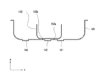
- the bead 142 of the lower tank 120 according to the above embodiment is formed as a convex beat in which the bottom surface portion 142 protrudes in the negative z-axis direction from the internal space in which the auxiliary tank 130 is provided.
- the auxiliary tank 130 is spot-welded to the lower tank 120 at flat portions on both sides of the bead 142.
- regions corresponding to both sides of a substantially center line in the width direction of the auxiliary tank 130 of the lower tank 120 are projected toward the inner space side of the lower tank 120 to form convex line portions 142a and 142b.
- the flat surface on the inner space side of the line portions 142a and 142b is used as a flat region necessary for spot welding the auxiliary tank 130 to the lower tank 120.
- a convex beat 142 protruding from the flat surface of the line portions 142a and 142b in the negative z-axis direction is formed.
- the sub beads 144 and 146 and the embossed portions 160a to 160d formed on the bottom surface portion 124 of the lower tank 120 may be formed in a convex shape or a concave shape.
- the sub beads 144 and 146 are formed on both sides of the bead 142.
- the present invention is not limited to this example, and one or a plurality of sub beads may be formed on the bottom surface portion 124 of the lower tank 120.
- the sub-bead is formed so as to be substantially parallel to the bead 142 and continuous in the longitudinal direction of the fuel tank 100.
- the auxiliary tank 130 is fixed to the lower tank 120 with the six spot welds 150a to 150f, but the present invention is not limited to such an example.
- the number and welding positions of the spot welds 150 can be appropriately determined according to the size of the auxiliary tank 130 with respect to the lower tank 120 and the like.
- the bead 142 and the sub-beads 144 and 146 formed on both sides of the bead 142 are described as being linear (see FIG. 3 and the like).
- the beads 142 may meander in the width direction within a distance range between the spot welds 150 in the x direction).
- the width of the bead 142 may be changed within a distance range between the spot welds 150 in the width direction of the auxiliary tank 130 as shown in FIG.
- a support member for piping, a wave-dissipating plate, or the like may be attached to the inside of the fuel tank 100 by spot welding.
- the spot weld 150 and the bead 142 may interfere with each other as they are.
- the meandering range of the meandering bead or the change width of the width-changing bead is within the distance range between the spot welds 150, the reduction of the natural frequency is suppressed to about 10% with respect to the linear bead. High rigidity.
- the bead 142A may be formed continuously from the bottom surface portion 124 to the side wall portion 122. is there. In this way, by extending the bead 142A up to the region of the side wall portion 122, a three-dimensional structure by the bead 142A is constructed across the bottom surface portion 124 and the side wall portion 122, whereby the overall rigidity can be increased.
- the present invention it is possible to increase the rigidity of the fuel tank, effectively prevent fatigue fracture of the welded portion of the auxiliary tank and the lower tank due to vertical vibrations while the vehicle is running, and have extremely excellent durability and reliability.
- a fuel tank is realized.
Landscapes
- Engineering & Computer Science (AREA)
- Life Sciences & Earth Sciences (AREA)
- Sustainable Development (AREA)
- Sustainable Energy (AREA)
- Chemical & Material Sciences (AREA)
- Combustion & Propulsion (AREA)
- Transportation (AREA)
- Mechanical Engineering (AREA)
- Cooling, Air Intake And Gas Exhaust, And Fuel Tank Arrangements In Propulsion Units (AREA)
Abstract
Description
[1-1.燃料タンクの外観例]
まず、図1~図3に基づいて、本発明の第1の実施形態に係る車両用燃料タンク100の概略構成について説明する。なお、図1は、本実施形態に係る車両用燃料タンク100の外観を示す斜視図である。図2は、本実施形態に係る車両用燃料タンク100のロアタンク120の内部を示す斜視図である。図3は、図2の平面図である。なお、以下では、燃料タンク100の長手方向を車両の進行方向とし、説明する。
(A.ビード長さ)
まず、図3~図8に基づいて、ロアタンク120に形成されるビード142の長手方向における長さLBについて説明する。ビード142の長さLBは、ロアタンク120の底面部124のR形状が形成されていない部分の平坦部分長さLの約80%以上の長さとするのが望ましい。ビード142の長さLBをかかる長さとすることにより、2次パネル振動モードの固有振動数を最大10%まで低下に抑えることができ、燃料タンク100の剛性を十分に保持することができる。これにより、走行中の上下振動による補助タンク130とロアタンク120とを締結するスポット溶接部150の疲労破壊を、燃料タンク100の供用期間中にわたって防止することができる。
逆に、2次パネル振動モードの固有振動数が10%を超えて低下すると、燃料タンク100の剛性が不十分となり、燃料タンク100の供用期間中にスポット溶接部150の疲労破壊の発生がたびたび見られることが分かった。

次に、図9および図10に基づいて、ビード142のx方向におけるビード幅WBについて説明する。本実施形態に係るロアタンク120に形成するビード142のビード幅WBは、x方向に隣接する2列のスポット溶接部150a~150cと150d~150fとの間隔(「スポット溶接間距離」ともいう。)WSの約50%以上の長さとするのが望ましい。ビード幅WBをスポット溶接間距離WSの約50%以上の長さとすることにより、2次パネル振動モードの固有振動数を約10%程度の低下に抑えることができ、燃料タンク100の剛性を十分に保持することができる。
本実施形態に係るロアタンク120には、補助タンク130のロアタンク幅WLの略中心線上において長手方向に形成された継ぎ目のない連続したビード142の両側に、サブビード144、146が形成されている。サブビード144、146は、ロアタンク120の剛性をより高めるために補助的に形成される。サブビード144、146は、ロアタンク120の幅方向において、補助タンク130の端面からロアタンク120の曲がり部のR形状止まりまでの平坦部分(「サブビード配置可能幅WA」ともいう。)に形成すればよい。例えば、サブビード144、146は、サブビード配置可能幅WA内において、図11に示すように補助タンク130側に形成してもよく、図12に示すようにロアタンク120の側面側に形成してもよい。
本実施形態に係るロアタンク120は、補助タンク130のロアタンク幅WLの略中心線上において長手方向に形成された継ぎ目のない連続したビード142を形成することにより、2次パネル振動モードの固有振動数の大きな低下を抑制する。ここで、従来構成の燃料タンクと比較し、ビード142をロアタンク120の底面部124に長手方向に連続して形成することによる効果を、検証するシミュレーションを行った。
(A.ビードの長手方向延長周辺領域)
更に、本実施形態に係るロアタンク120において、補助タンク130の底面部分に形成されるビードの長手方向延長周辺には異なる方向のビードが形成されないことが剛性確保に極めて効果的である。ここに、ビードの長手方向延長周辺とは補助タンク130の外側であって、当該ビード自体およびその長手方向延長上を含む広がりを持った領域周辺を意味する。
すなわち、ロアタンク120の長手方向の十分な長さのビードがない場合は、その長手方向延長上に異なる方向のビードを設置すると固有振動数の低下を防止する効果が実質的に得られない。
一方、ロアタンク120の長手方向のビードが十分な長さである場合、即ち、ロアタンク120の底面における平坦部の長手方向の80%以上の長さのビードがある場合には、異なる方向あるいは同じ方向のビードを当該ビードの延長上のわずかな部分に設置してもその影響はない、即ち固有振動数は変化しない。
図18および図19はこのモデルにおける二次パネル振動モードのシミュレーション結果を示している。これらの図に示されるように異なる方向のビードとして長手方向と直角方向のビード140が存在する不連続部分において局所的に剛性が低下して振動の最大変位箇所となり、結果としてビード142の長手方向延長周辺に異なる方向のビード140が形成されると剛性が低下することになる。従って、ビード142の長手方向延長周辺には異なる方向のビードが形成されないことが好適である。
また、本実施形態に係るロアタンク120において、補助タンク130の下面はビードを除き、ロアタンク120の底面部と接触しない部位を持たないことがスポット溶接部の破壊強度確保に極めて効果的である。
図23および図24はこのモデルにおける二次パネル振動モードのシミュレーション結果を示している。これらの図に示されるように補助タンク130の下面とロアタンク120の底面とが接触していないサブビード141の部分が存在するため、補助タンク130の結合が不安定になると共に、問題となる二次パネル振動モードにおいてはビード配列が不均一な配置となることから、片側の特定のスポット溶接部(ビード142とサブビード144との間のスポット溶接部150)に荷重が集中する形態となり、このスポット溶接部の破壊を誘発することになる。従って、補助タンク130の下面はビード142を除き、ロアタンク120の底面部と接触しない部位を持たないことが好適である。
次に、図25および図26に基づいて、本発明の第2の実施形態に係る車両用燃料タンク100について説明する。なお、図25は、本実施形態に係る燃料タンク100の一構成を示す平面図である。図26は、本実施形態に係る燃料タンク100の他の構成を示す平面図である。
なお、ロアタンク120の底面部124に形成されるサブビード144、146、エンボス部160a~160dは、凸形状で形成されても、凹形状で形成されてもよい。
あるいはまた、図30のように補助タンク130の幅方向のスポット溶接部150間の距離範囲内で、ビード142の幅を変化させてもよい。
このようにビード142Aを側壁部122の領域まで延設することで、底面部124および側壁部122に亘ってビード142Aよる立体的構造が構築され、これにより全体としての剛性を高めることができる。
Claims (9)
- アッパータンクおよびロアタンクが相互に接合されて、燃料が収容される閉空間を形成するタンク本体と、前記ロアタンクの底面部にスポット溶接により固定される補助タンクと、からなり、
前記スポット溶接は前記補助タンクの幅方向で距離をおいて、前記ロアタンクの長手方向に沿って複数列設定され、
前記ロアタンクの底面部においてその長手方向に沿って連続して延びる、前記スポット溶接の列間に位置する少なくとも1つのビードが形成されるとともに、
前記補助タンクの下面は前記ビードを除き、前記ロアタンクの底面部と接触しない部位を持たないことを特徴とする車両用燃料タンク。 - 前記ビードの長さは、長手方向における前記ロアタンクの底面部の平坦部分長さの80%以上の長さに形成されることを特徴とする請求項1に記載の車両用燃料タンク。
- 前記ビードは、前記ロアタンクの底面部から側壁部まで連続して形成されることを特徴とする請求項2に記載の車両用燃料タンク。
- 前記複数列のスポット溶接は、前記補助タンクの幅方向の略中心線上に形成された前記ビードに関して対称に配置されることを特徴とする請求項1に記載の車両用燃料タンク。
- 前記ビードの幅は、該ビードを挟んで隣接する前記スポット溶接の列間隔の50%以上の長さに形成されることを特徴とする請求項4に記載の車両用燃料タンク。
- 列方向に隣接する前記スポット溶接間に、前記ロアタンクの底面部に対して垂直方向に形成されるエンボス部を有することを特徴とする請求項4に記載の車両用燃料タンク。
- 前記ロアタンクの底面部においてその長手方向に沿って、前記補助タンクの幅方向における端面から前記ロアタンクの側壁部までの間の平坦部分に別のビードが形成されることを特徴とする請求項1に記載の車両用燃料タンク。
- 前記ビードは幅方向に蛇行した蛇行ビードもしくは、幅を変化させた幅変化ビードに形成されることを特徴とする請求項4に記載の車両用燃料タンク。
- 前記タンク本体および前記補助タンクは、表面処理鋼板、ステンレス鋼、またはアルミニウム合金のうち少なくともいずれか1つの材料からなり、
前記ロアタンクと前記補助タンクとは、同一材質で形成されることを特徴とする請求項1に記載の車両用燃料タンク。
Priority Applications (7)
| Application Number | Priority Date | Filing Date | Title |
|---|---|---|---|
| MX2013003712A MX336511B (es) | 2010-10-05 | 2011-10-04 | Tanque de combustible para vehiculo. |
| EP11830665.3A EP2626228B1 (en) | 2010-10-05 | 2011-10-04 | Fuel tank for vehicle |
| US13/823,676 US9944169B2 (en) | 2010-10-05 | 2011-10-04 | Fuel tank for vehicle |
| BR112013009257A BR112013009257A2 (pt) | 2010-10-05 | 2011-10-04 | tanque de combustível para veículo |
| CN201180048146.8A CN103153672B (zh) | 2010-10-05 | 2011-10-04 | 车辆用燃料箱 |
| KR1020137008428A KR101473125B1 (ko) | 2010-10-05 | 2011-10-04 | 차량용 연료 탱크 |
| JP2012504949A JP5351330B2 (ja) | 2010-10-05 | 2011-10-04 | 車両用燃料タンク |
Applications Claiming Priority (2)
| Application Number | Priority Date | Filing Date | Title |
|---|---|---|---|
| JP2010225454 | 2010-10-05 | ||
| JP2010-225454 | 2010-10-05 |
Publications (1)
| Publication Number | Publication Date |
|---|---|
| WO2012046733A1 true WO2012046733A1 (ja) | 2012-04-12 |
Family
ID=45927728
Family Applications (1)
| Application Number | Title | Priority Date | Filing Date |
|---|---|---|---|
| PCT/JP2011/072878 Ceased WO2012046733A1 (ja) | 2010-10-05 | 2011-10-04 | 車両用燃料タンク |
Country Status (9)
| Country | Link |
|---|---|
| US (1) | US9944169B2 (ja) |
| EP (1) | EP2626228B1 (ja) |
| JP (2) | JP5351330B2 (ja) |
| KR (1) | KR101473125B1 (ja) |
| CN (1) | CN103153672B (ja) |
| BR (1) | BR112013009257A2 (ja) |
| MX (1) | MX336511B (ja) |
| TW (1) | TWI462845B (ja) |
| WO (1) | WO2012046733A1 (ja) |
Cited By (2)
| Publication number | Priority date | Publication date | Assignee | Title |
|---|---|---|---|---|
| FR3004388A1 (fr) * | 2013-04-16 | 2014-10-17 | Peugeot Citroen Automobiles Sa | Reservoir embarque sous le plancher de charge d'un vehicule |
| CN105501344A (zh) * | 2015-12-10 | 2016-04-20 | 重庆慧团商贸有限公司 | 并联多腔摩托车防爆油箱 |
Families Citing this family (2)
| Publication number | Priority date | Publication date | Assignee | Title |
|---|---|---|---|---|
| CN105059108B (zh) * | 2015-07-24 | 2017-11-14 | 盐城市富源油箱有限公司 | 一种扫雪机油箱的制作方法 |
| US20160375525A1 (en) * | 2016-09-07 | 2016-12-29 | Yu-Peng Chan | Process of manufacturing fuel tank |
Citations (8)
| Publication number | Priority date | Publication date | Assignee | Title |
|---|---|---|---|---|
| JPH0659117U (ja) * | 1993-01-27 | 1994-08-16 | ダイハツ工業株式会社 | 自動車用燃料タンク |
| JP2515941Y2 (ja) * | 1990-01-22 | 1996-11-06 | ダイハツ工業株式会社 | 燃料タンクのサブタンク取付構造 |
| JPH1044793A (ja) | 1996-07-30 | 1998-02-17 | Daihatsu Motor Co Ltd | フューエルタンクにおけるサブタンクの取付け構造 |
| JPH10265967A (ja) * | 1997-03-27 | 1998-10-06 | Nippon Steel Corp | プレス成形性及び耐食性に優れた燃料タンク用防錆鋼板 |
| JP2000158956A (ja) | 1998-11-30 | 2000-06-13 | Suzuki Motor Corp | 自動車用燃料タンク |
| JP2002067711A (ja) | 2000-09-04 | 2002-03-08 | Suzuki Motor Corp | 自動車の燃料タンク構造 |
| JP2002321537A (ja) | 2001-04-25 | 2002-11-05 | Suzuki Motor Corp | 車両用燃料タンク |
| JP2002321534A (ja) * | 2001-04-27 | 2002-11-05 | Suzuki Motor Corp | 車両用燃料タンク |
Family Cites Families (18)
| Publication number | Priority date | Publication date | Assignee | Title |
|---|---|---|---|---|
| US3648886A (en) * | 1970-05-11 | 1972-03-14 | William L Pringle | Fuel tank assembly |
| US3701540A (en) * | 1971-12-10 | 1972-10-31 | William L Pringle And Associat | Fuel tank assembly |
| US5496069A (en) * | 1991-09-20 | 1996-03-05 | Milligan; Frank | Heat management shielding device |
| JP2955897B2 (ja) | 1991-10-31 | 1999-10-04 | 本田技研工業株式会社 | 車両用燃料供給装置 |
| JP2744424B2 (ja) | 1996-03-11 | 1998-04-28 | ダイハツ工業株式会社 | 車両用燃料タンク |
| KR980007296U (ko) * | 1996-07-04 | 1998-04-30 | 김영귀 | 자동차용 연료탱크의 비드 |
| KR100453387B1 (ko) | 1996-07-31 | 2004-10-15 | 신닛뽄세이테쯔 카부시키카이샤 | 저항 용접성, 내식성, 프레스 성형성이 뛰어난 자동차 연료용기용 방청 강판 |
| JP3438897B2 (ja) * | 1997-03-21 | 2003-08-18 | 三菱重工業株式会社 | 燃料タンク及びこれを備えた汎用エンジン |
| JP3846658B2 (ja) | 1997-12-05 | 2006-11-15 | スズキ株式会社 | 車両用フューエルタンクの構造 |
| DE19846895A1 (de) | 1998-10-13 | 2000-04-20 | Elenac Gmbh | Kraftstoffbehälter für Kraftfahrzeuge mit Brennstoffzellenantrieb |
| DE10054876C2 (de) * | 2000-11-06 | 2002-11-07 | Sig Kautex Gmbh & Co Kg | Doppelwandiger Kraftstoffbehälter aus Kunststoff |
| US6782745B1 (en) * | 2003-02-21 | 2004-08-31 | Visteon Global Technologies, Inc. | Slosh supressor and heat sink |
| JP2005199880A (ja) * | 2004-01-16 | 2005-07-28 | Suzuki Motor Corp | 燃料タンクの容器構造 |
| JP2005297820A (ja) | 2004-04-13 | 2005-10-27 | Mitsubishi Motors Corp | 燃料タンク |
| JP2007009806A (ja) * | 2005-06-30 | 2007-01-18 | Mitsubishi Electric Corp | 燃料供給装置 |
| JP5258253B2 (ja) | 2006-11-21 | 2013-08-07 | 新日鐵住金ステンレス株式会社 | 塩害耐食性および溶接部信頼性に優れた自動車用燃料タンク用および自動車燃料パイプ用表面処理ステンレス鋼板および拡管加工性に優れた自動車給油管用表面処理ステンレス鋼溶接管 |
| JP5311203B2 (ja) * | 2008-10-31 | 2013-10-09 | スズキ株式会社 | 燃料タンク支持構造 |
| US20160075227A1 (en) * | 2015-11-29 | 2016-03-17 | Yu-Peng Chan | Automotive fuel tank |
-
2011
- 2011-10-04 EP EP11830665.3A patent/EP2626228B1/en active Active
- 2011-10-04 KR KR1020137008428A patent/KR101473125B1/ko active Active
- 2011-10-04 CN CN201180048146.8A patent/CN103153672B/zh active Active
- 2011-10-04 US US13/823,676 patent/US9944169B2/en active Active
- 2011-10-04 MX MX2013003712A patent/MX336511B/es unknown
- 2011-10-04 JP JP2012504949A patent/JP5351330B2/ja active Active
- 2011-10-04 WO PCT/JP2011/072878 patent/WO2012046733A1/ja not_active Ceased
- 2011-10-04 BR BR112013009257A patent/BR112013009257A2/pt active Search and Examination
- 2011-10-05 TW TW100136049A patent/TWI462845B/zh not_active IP Right Cessation
-
2013
- 2013-06-25 JP JP2013132357A patent/JP5621886B2/ja active Active
Patent Citations (8)
| Publication number | Priority date | Publication date | Assignee | Title |
|---|---|---|---|---|
| JP2515941Y2 (ja) * | 1990-01-22 | 1996-11-06 | ダイハツ工業株式会社 | 燃料タンクのサブタンク取付構造 |
| JPH0659117U (ja) * | 1993-01-27 | 1994-08-16 | ダイハツ工業株式会社 | 自動車用燃料タンク |
| JPH1044793A (ja) | 1996-07-30 | 1998-02-17 | Daihatsu Motor Co Ltd | フューエルタンクにおけるサブタンクの取付け構造 |
| JPH10265967A (ja) * | 1997-03-27 | 1998-10-06 | Nippon Steel Corp | プレス成形性及び耐食性に優れた燃料タンク用防錆鋼板 |
| JP2000158956A (ja) | 1998-11-30 | 2000-06-13 | Suzuki Motor Corp | 自動車用燃料タンク |
| JP2002067711A (ja) | 2000-09-04 | 2002-03-08 | Suzuki Motor Corp | 自動車の燃料タンク構造 |
| JP2002321537A (ja) | 2001-04-25 | 2002-11-05 | Suzuki Motor Corp | 車両用燃料タンク |
| JP2002321534A (ja) * | 2001-04-27 | 2002-11-05 | Suzuki Motor Corp | 車両用燃料タンク |
Non-Patent Citations (1)
| Title |
|---|
| See also references of EP2626228A4 |
Cited By (2)
| Publication number | Priority date | Publication date | Assignee | Title |
|---|---|---|---|---|
| FR3004388A1 (fr) * | 2013-04-16 | 2014-10-17 | Peugeot Citroen Automobiles Sa | Reservoir embarque sous le plancher de charge d'un vehicule |
| CN105501344A (zh) * | 2015-12-10 | 2016-04-20 | 重庆慧团商贸有限公司 | 并联多腔摩托车防爆油箱 |
Also Published As
| Publication number | Publication date |
|---|---|
| EP2626228B1 (en) | 2019-12-04 |
| US9944169B2 (en) | 2018-04-17 |
| EP2626228A1 (en) | 2013-08-14 |
| KR101473125B1 (ko) | 2014-12-15 |
| TW201221380A (en) | 2012-06-01 |
| JPWO2012046733A1 (ja) | 2014-02-24 |
| US20130168397A1 (en) | 2013-07-04 |
| CN103153672A (zh) | 2013-06-12 |
| TWI462845B (zh) | 2014-12-01 |
| JP5621886B2 (ja) | 2014-11-12 |
| EP2626228A4 (en) | 2018-04-18 |
| JP5351330B2 (ja) | 2013-11-27 |
| KR20130066680A (ko) | 2013-06-20 |
| CN103153672B (zh) | 2016-01-20 |
| MX336511B (es) | 2016-01-22 |
| MX2013003712A (es) | 2013-04-24 |
| BR112013009257A2 (pt) | 2016-07-26 |
| JP2013216317A (ja) | 2013-10-24 |
Similar Documents
| Publication | Publication Date | Title |
|---|---|---|
| JP5028893B2 (ja) | アンダーカバー | |
| JP5621886B2 (ja) | 車両用燃料タンク | |
| JP6005367B2 (ja) | 溶接ビードを用いた板構造体の補強方法 | |
| JP2011225107A (ja) | 車体後部のブラケット構造 | |
| JP6649422B2 (ja) | 車両用ドア構造 | |
| US9598118B2 (en) | Vehicular floor brace | |
| US20050028478A1 (en) | Joining structure | |
| JP5696467B2 (ja) | 車両用燃料タンク | |
| WO2014136261A1 (ja) | トーションビーム式サスペンション | |
| JP5365660B2 (ja) | 車両下部構造 | |
| JP2009269593A (ja) | 燃料タンクユニット | |
| JP5263375B2 (ja) | アンダーカバー | |
| JP2019089457A (ja) | ゴムクローラ | |
| JP2018159193A (ja) | 梁補強金具および梁補強構造 | |
| JP6036216B2 (ja) | 燃料タンクの内部構造 | |
| JPH11165544A (ja) | 車両用フューエルタンクの構造 | |
| JP6575405B2 (ja) | 溶接構造部材 | |
| JP2004123052A (ja) | フューエルタンク構造 | |
| US20180291938A1 (en) | Weld joint assembly | |
| CN116039764B (zh) | 副车架总成和车辆 | |
| JP2011230602A (ja) | 車両前部構造 | |
| JP2009051460A (ja) | 燃料タンク | |
| JP2002321537A (ja) | 車両用燃料タンク | |
| JP5737045B2 (ja) | 車両カウルトップ構造 | |
| JP2018108773A (ja) | 車両用燃料タンク |
Legal Events
| Date | Code | Title | Description |
|---|---|---|---|
| WWE | Wipo information: entry into national phase |
Ref document number: 201180048146.8 Country of ref document: CN |
|
| WWE | Wipo information: entry into national phase |
Ref document number: 2012504949 Country of ref document: JP |
|
| 121 | Ep: the epo has been informed by wipo that ep was designated in this application |
Ref document number: 11830665 Country of ref document: EP Kind code of ref document: A1 |
|
| WWE | Wipo information: entry into national phase |
Ref document number: 13823676 Country of ref document: US |
|
| WWE | Wipo information: entry into national phase |
Ref document number: 2011830665 Country of ref document: EP |
|
| ENP | Entry into the national phase |
Ref document number: 20137008428 Country of ref document: KR Kind code of ref document: A |
|
| WWE | Wipo information: entry into national phase |
Ref document number: MX/A/2013/003712 Country of ref document: MX |
|
| NENP | Non-entry into the national phase |
Ref country code: DE |
|
| REG | Reference to national code |
Ref country code: BR Ref legal event code: B01A Ref document number: 112013009257 Country of ref document: BR |
|
| ENP | Entry into the national phase |
Ref document number: 112013009257 Country of ref document: BR Kind code of ref document: A2 Effective date: 20130404 |