WO2012049980A1 - 蓄電システム - Google Patents
蓄電システム Download PDFInfo
- Publication number
- WO2012049980A1 WO2012049980A1 PCT/JP2011/072534 JP2011072534W WO2012049980A1 WO 2012049980 A1 WO2012049980 A1 WO 2012049980A1 JP 2011072534 W JP2011072534 W JP 2011072534W WO 2012049980 A1 WO2012049980 A1 WO 2012049980A1
- Authority
- WO
- WIPO (PCT)
- Prior art keywords
- storage system
- secondary battery
- rack
- power
- conversion device
- Prior art date
- Legal status (The legal status is an assumption and is not a legal conclusion. Google has not performed a legal analysis and makes no representation as to the accuracy of the status listed.)
- Ceased
Links
Images




Classifications
-
- H—ELECTRICITY
- H01—ELECTRIC ELEMENTS
- H01M—PROCESSES OR MEANS, e.g. BATTERIES, FOR THE DIRECT CONVERSION OF CHEMICAL ENERGY INTO ELECTRICAL ENERGY
- H01M10/00—Secondary cells; Manufacture thereof
- H01M10/42—Methods or arrangements for servicing or maintenance of secondary cells or secondary half-cells
- H01M10/425—Structural combination with electronic components, e.g. electronic circuits integrated to the outside of the casing
-
- H—ELECTRICITY
- H01—ELECTRIC ELEMENTS
- H01M—PROCESSES OR MEANS, e.g. BATTERIES, FOR THE DIRECT CONVERSION OF CHEMICAL ENERGY INTO ELECTRICAL ENERGY
- H01M10/00—Secondary cells; Manufacture thereof
- H01M10/42—Methods or arrangements for servicing or maintenance of secondary cells or secondary half-cells
- H01M10/46—Accumulators structurally combined with charging apparatus
-
- H—ELECTRICITY
- H01—ELECTRIC ELEMENTS
- H01M—PROCESSES OR MEANS, e.g. BATTERIES, FOR THE DIRECT CONVERSION OF CHEMICAL ENERGY INTO ELECTRICAL ENERGY
- H01M50/00—Constructional details or processes of manufacture of the non-active parts of electrochemical cells other than fuel cells, e.g. hybrid cells
- H01M50/20—Mountings; Secondary casings or frames; Racks, modules or packs; Suspension devices; Shock absorbers; Transport or carrying devices; Holders
- H01M50/204—Racks, modules or packs for multiple batteries or multiple cells
-
- H—ELECTRICITY
- H01—ELECTRIC ELEMENTS
- H01M—PROCESSES OR MEANS, e.g. BATTERIES, FOR THE DIRECT CONVERSION OF CHEMICAL ENERGY INTO ELECTRICAL ENERGY
- H01M50/00—Constructional details or processes of manufacture of the non-active parts of electrochemical cells other than fuel cells, e.g. hybrid cells
- H01M50/50—Current conducting connections for cells or batteries
- H01M50/502—Interconnectors for connecting terminals of adjacent batteries; Interconnectors for connecting cells outside a battery casing
-
- H—ELECTRICITY
- H02—GENERATION; CONVERSION OR DISTRIBUTION OF ELECTRIC POWER
- H02J—ELECTRIC POWER NETWORKS; CIRCUIT ARRANGEMENTS OR SYSTEMS FOR SUPPLYING OR DISTRIBUTING ELECTRIC POWER; SYSTEMS FOR STORING ELECTRIC ENERGY
- H02J7/00—Circuit arrangements for charging or discharging batteries or for supplying loads from batteries
- H02J7/70—Circuit arrangements for charging or discharging batteries or for supplying loads from batteries characterised by the mechanical construction
-
- H—ELECTRICITY
- H01—ELECTRIC ELEMENTS
- H01M—PROCESSES OR MEANS, e.g. BATTERIES, FOR THE DIRECT CONVERSION OF CHEMICAL ENERGY INTO ELECTRICAL ENERGY
- H01M10/00—Secondary cells; Manufacture thereof
- H01M10/42—Methods or arrangements for servicing or maintenance of secondary cells or secondary half-cells
- H01M10/425—Structural combination with electronic components, e.g. electronic circuits integrated to the outside of the casing
- H01M2010/4271—Battery management systems including electronic circuits, e.g. control of current or voltage to keep battery in healthy state, cell balancing
-
- H—ELECTRICITY
- H01—ELECTRIC ELEMENTS
- H01M—PROCESSES OR MEANS, e.g. BATTERIES, FOR THE DIRECT CONVERSION OF CHEMICAL ENERGY INTO ELECTRICAL ENERGY
- H01M2220/00—Batteries for particular applications
- H01M2220/10—Batteries in stationary systems, e.g. emergency power source in plant
-
- H—ELECTRICITY
- H01—ELECTRIC ELEMENTS
- H01M—PROCESSES OR MEANS, e.g. BATTERIES, FOR THE DIRECT CONVERSION OF CHEMICAL ENERGY INTO ELECTRICAL ENERGY
- H01M50/00—Constructional details or processes of manufacture of the non-active parts of electrochemical cells other than fuel cells, e.g. hybrid cells
- H01M50/20—Mountings; Secondary casings or frames; Racks, modules or packs; Suspension devices; Shock absorbers; Transport or carrying devices; Holders
- H01M50/271—Lids or covers for the racks or secondary casings
-
- Y—GENERAL TAGGING OF NEW TECHNOLOGICAL DEVELOPMENTS; GENERAL TAGGING OF CROSS-SECTIONAL TECHNOLOGIES SPANNING OVER SEVERAL SECTIONS OF THE IPC; TECHNICAL SUBJECTS COVERED BY FORMER USPC CROSS-REFERENCE ART COLLECTIONS [XRACs] AND DIGESTS
- Y02—TECHNOLOGIES OR APPLICATIONS FOR MITIGATION OR ADAPTATION AGAINST CLIMATE CHANGE
- Y02E—REDUCTION OF GREENHOUSE GAS [GHG] EMISSIONS, RELATED TO ENERGY GENERATION, TRANSMISSION OR DISTRIBUTION
- Y02E60/00—Enabling technologies; Technologies with a potential or indirect contribution to GHG emissions mitigation
- Y02E60/10—Energy storage using batteries
Definitions
- the present invention relates to a power storage system, and more particularly to a power storage system provided with a plurality of secondary battery storage system racks for storing secondary batteries therein.
- Energy is effectively used by using power storage devices such as secondary batteries.
- power storage devices such as secondary batteries.
- a photovoltaic power generation system has been actively developed as environmentally friendly clean energy, but since a photoelectric conversion module that converts sunlight into electric power does not have a storage function, it is combined with a secondary battery.
- energy is effectively used by charge / discharge control in which electric power generated by a photoelectric conversion module is once charged in a secondary battery and discharged from the secondary battery in response to a request from an external load or the like.
- Patent Document 1 discloses a solar battery, a plurality of secondary batteries charged by the solar battery, and a secondary battery connected between each secondary battery and the solar battery.
- a solar battery power supply device comprising: a charge switch for controlling charging of a secondary battery; a discharge switch connected between each secondary battery and a load; and a control circuit for controlling the charge switch and the discharge switch. It is disclosed.
- the control circuit specifies the priority order of the secondary batteries to be charged by controlling a plurality of charge switches, charges the secondary battery with a higher priority before the secondary battery with a lower priority, It is disclosed that when a secondary battery having a higher rank is charged with a predetermined capacity, a secondary battery having a lower priority is charged.
- the secondary battery storage system racks 13a to 13d for storing the secondary battery therein. May be used more than once.
- One power conversion device 20 may be provided in common for the plurality of secondary battery storage system racks 13a to 13d.
- the secondary battery storage system racks 13a to 13d, the power conversion device 20, May be connected by a power line.
- the positive bus 1 connects the positive terminals 41 in the order of the secondary battery storage system racks 13 a, 13 b, 13 c, and 13 d from the positive terminal 21 of the power conversion device 20.
- the negative electrode bus 2 connects the negative electrode side terminals 42 to each other in the order of the secondary battery storage system racks 13a, 13b, 13c, and 13d from the negative electrode side terminal 22 of the power conversion device 20.
- a secondary battery storage system rack having a positive terminal 41 connected directly to the positive terminal 21 of the power converter 20 and a negative terminal 42 connected directly to the negative terminal 22 of the power converter 20 are provided.
- the secondary battery storage system rack has the same secondary battery storage system rack 13a. For this reason, a large current concentration occurs in the secondary battery storage system rack 13a.
- the current value of the secondary battery storage system rack 13a is the largest, and the current value decreases in the order of the secondary battery storage system racks 13b, 13c, 13d.
- An object of the present invention is to provide a power storage system capable of suppressing current concentration when a plurality of secondary battery storage system racks and a power conversion device are wired using a power line.
- the power storage system according to the present invention is provided in common to a plurality of secondary battery storage system racks that respectively store secondary batteries and circuit blocks, and to each circuit block of the plurality of secondary battery storage system racks.
- a secondary battery storage system rack having a positive terminal connected directly to a positive terminal of the power converter by a positive bus, and a direct connection to a negative terminal of the power converter by a negative bus This is different from the secondary battery storage system rack having the negative electrode side terminal.
- the secondary battery storage system rack having the positive electrode side terminal directly connected to the positive electrode side terminal of the power converter by the positive electrode bus, and the negative electrode directly connected to the negative electrode terminal of the power converter by the negative electrode bus. Since it can be different from the secondary battery storage system rack having the side terminals, current concentration due to impedances such as wiring can be suppressed.
- FIG. 6 is a sectional view taken along line BB of FIG. It is a figure which shows the electrical storage system of a prior art.
- a lithium ion secondary battery is used as the secondary battery, but other secondary batteries may be used.
- a nickel hydrogen battery, a nickel cadmium battery, or the like may be used.
- the secondary battery is used as an assembled battery composed of a plurality of single cells. The reason why the assembled battery is used is that a plurality of single cells are combined to obtain a desired high voltage. Therefore, the number of single cells constituting the assembled battery can be appropriately changed according to the specification.
- the dimensions, shapes, materials, and the like described below are examples for explanation, and can be appropriately changed according to the specifications of the secondary battery storage system rack. Further, the number of secondary batteries stored in the secondary battery block described below, the number of secondary battery storage system racks constituting the power storage system, and the like are examples.
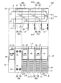
- FIG. 1 is a diagram showing a power storage system 98.
- FIG. 1 shows a top view (upper side of FIG. 1) and a front view (lower side of FIG. 1) of the power storage system 98.
- the power storage system 98 includes a power conversion device storage rack 18 and secondary battery storage system racks 13a to 13d.
- the secondary battery storage system racks 13a to 13d are aligned and arranged in one row and four columns.
- FIG. 1 in the power storage system 98, the front door 19 of the power conversion device storage rack 18, the front door 14 of the secondary battery storage system rack 13b, the front door 14 of the secondary battery storage system rack 13c, A state in which the front door 14 of the secondary battery storage system rack 13d is opened is shown.
- the power conversion device storage rack 18 stores the power conversion device 20 therein.
- the power conversion device storage rack 18 has a box shape extending in the vertical direction, and has a bottom surface and a ceiling surface that are in contact with the installation surface and a substantially rectangular shape, three sides are surrounded by side wall members as outer wall portions, and the other one can be opened and closed. It is a front door 19.
- the side wall member and the front door 19 of the power converter housing rack 18 are formed using a material having appropriate strength, for example, a stainless steel material.
- the front door 19 side front door 14 side
- the side other than the front door 19 side front door 14 side
- the power conversion device 20 receives power from the grid, converts the secondary battery 140 stored in the secondary battery storage system racks 13a to 13d to appropriate DC power, and converts the secondary battery 140 into power.
- the discharged power from the battery 140 has a function of performing power conversion for supplying power to the system load.
- the power conversion device 20 includes a positive terminal 21 for supplying a positive potential necessary for operating the device and a negative side for supplying a negative potential necessary for operating the device. And a terminal 22. Moreover, the positive electrode side terminal 21 and the negative electrode side terminal 22 are provided so that it may protrude above the ceiling part of the power converter housing rack 18. In addition, when an example of the dimension of the power converter storage rack 18 is shown, the bottom surface is about 70 cm ⁇ about 70 cm, and the height is about 240 cm.
- the secondary battery storage system racks 13a to 13d function as racks for storing the secondary battery 140 and the circuit block 40 therein.
- the secondary battery storage system racks 13a to 13d have the same external shape, and each has a box shape elongated in the vertical direction.
- the bottom surface and the ceiling surface in contact with the installation surface have a substantially square shape, and three sides are side walls as outer wall portions.
- the front door 14 is surrounded by a member and the other one is openable and closable.
- the secondary battery storage system racks 13a to 13d are arranged adjacent to each other.
- the side wall member and the front door 14 are formed using a material having an appropriate strength, for example, a stainless steel material.
- a material having an appropriate strength for example, a stainless steel material.
- the bottom surface is about 70 cm ⁇ about 70 cm, and the height is about 240 cm.
- the intake fan portions 32 provided at the lower part of the front door 14 of the storage main body 12 respectively supply air to the inside from the outside of the secondary battery storage system racks 13a to 13d, respectively.
- the exhaust fan unit 30 provided at the upper part of the front door 14 has a function of discharging air from the inside of the secondary battery storage system racks 13a to 13d to the outside.
- the intake fan unit 32 and the exhaust fan unit 30 include an opening provided in the front door 14 and a fan attached to the front door 14 in accordance with the opening. The operations of the intake fan unit 32 and the exhaust fan unit 30 are controlled under the circuit block 40.
- the circuit block 40 stored in the storage main body 12 of the secondary battery storage system racks 13a to 13d includes a control unit and a breaker unit.
- the control unit is charged / discharged in the breaker unit or control unit according to the information (current value / voltage value / abnormality signal, etc.) from the breaker unit in charge or the secondary battery 140 or charge / discharge command transmitted from the outside It has a charge / discharge control function for controlling switches and the like.
- the breaker unit has a function of cutting off charge / discharge power between the power conversion device 20 and the secondary battery 140 under the control of the control unit.
- the circuit block 40 includes a positive terminal 41 for supplying a positive potential necessary for operating the device, and a negative electrode for supplying a negative potential necessary for operating the device. Side terminal 42.
- the positive terminal 41 and the negative terminal 42 are provided so as to protrude upward from the ceiling of the secondary battery storage system racks 13a to 13d.
- the circuit block 40 has been described as including the control unit and the breaker unit. However, it is not always necessary to include all the elements, and for example, the circuit block 40 may include only the breaker unit.
- the secondary battery 140 is a lithium ion assembled battery including an assembled battery case and a plurality of lithium ion secondary batteries housed therein.
- six secondary batteries 140 and six refractory heat insulating material plates 134 are alternately arranged in the vertical direction along the direction of gravity.
- the refractory heat insulating material plate 134 is a plate material for thermally separating the adjacent secondary batteries 140. Specifically, a calcium silicate plate having excellent fire resistance, heat insulating effect, and strength is used.
- the refractory heat insulating material plate 134 has a gas barrier property in the plate thickness direction so that even if one secondary battery 140 ignites, the ignition does not reach the adjacent secondary battery 140, and the processing hole It is the shielding flat plate which does not have openings, such as.
- the power conversion device storage rack 18 is arranged as shown in FIG.
- the secondary battery storage system rack 13a and the secondary battery storage system rack 13b are arranged from the power conversion device storage rack 18 side so that each front door 14 faces in the same direction as the front door 19 of the power conversion device storage rack 18.
- the secondary battery storage system rack 13c and the secondary battery storage system rack 13d are arranged adjacent to each other in this order. At this time, it is preferable to arrange the front doors 14 of the power conversion device storage rack 18 so that the surfaces of the front doors 14 coincide with each other when performing maintenance or the like.
- the positive electrode bus 1 engages with the protrusion 17 provided on the back side of the secondary battery storage system rack 13b from the positive terminal 21 of the power conversion device storage rack 18 and bypasses the secondary battery storage system racks 13a to 13c. Are connected to the positive terminal 41 of the secondary battery storage system rack 13d, and then the positive terminals 41 are connected in the order of the secondary battery storage system racks 13c, 13b, 13a. That is, the wiring path of the positive electrode bus 1 is routed so as to be substantially U-shaped when viewed from above.
- the negative electrode bus 2 connects the negative electrode side terminals 42 to each other in the order of the secondary battery storage system racks 13a, 13b, 13c, and 13d from the negative electrode side terminal 22 of the power conversion device storage rack 18.
- the secondary battery storage system rack having the positive terminal 41 connected directly to the positive terminal 21 of the power converter storage rack 18 and the negative terminal 22 of the power converter storage rack 18 are directly connected. This is different from the secondary battery storage system rack having the negative electrode side terminal 42. Thereby, current concentration due to the impedance of the wiring or the like can be suppressed.
- the “positive terminal 41 directly connected to the positive terminal 21” means the positive terminal 41 connected first when viewed from the positive terminal 21 among the positive terminals 41. To do.
- the “negative terminal 42 directly connected to the negative terminal 22” means the negative terminal 42 connected first when viewed from the negative terminal 22 among the negative terminals 42. To do.
- bus bar to be engaged with the protrusion 17 can be the negative electrode bus 2 instead of the positive electrode bus 1.
- FIG. 2 is a diagram illustrating the power storage system 99.
- the difference between the power storage system 99 and the power storage system 98 is the size of the power conversion device storage rack 18 and the alignment state of the secondary battery storage system racks 11a to 11d, and the difference will be mainly described.
- the secondary battery storage system racks 11a to 11d are arranged in two rows and two columns.
- the configurations of the secondary battery storage system racks 11a to 11d are the same as those of the secondary battery storage system racks 13a to 13d, and thus detailed description thereof is omitted.
- An example of the dimensions of the power conversion device storage rack 18 is about 70 cm ⁇ about 140 cm at the bottom and about 240 cm in height. Therefore, when two racks are adjacent to each other among the secondary battery storage system racks 11a to 11d, the size is the same.
- the power conversion device storage rack 18 is arranged as shown in FIG. Then, the secondary battery storage system rack 11a and the secondary battery storage from the power conversion device storage rack 18 side so that each front door 14 faces toward the back wall side with respect to the front door 19 of the power conversion device storage rack 18. They are arranged adjacent to each other in the order of the system rack 11b. At this time, it is preferable to arrange so that the surface of each front door 14 coincides with the surface of the rear wall with respect to the front door 19 of the power conversion device storage rack 18.
- the secondary battery storage system rack 11d and the secondary battery storage system rack 11c are arranged from the power conversion device storage rack 18 side so that each front door 14 faces in the same direction as the front door 19 of the power conversion device storage rack 18. Are arranged adjacent to each other in this order. At this time, it is preferable to arrange so that the surface of each front door 14 coincides with the front door 19 of the power conversion device storage rack 18.
- One end of the positive electrode bus 1 is connected to the positive electrode side terminal 21 of the power conversion device storage rack 18, and is connected to the positive electrode side terminal 41 of the secondary battery storage system rack 11 a adjacent to the power conversion device storage rack 18. Further, it is connected to the positive terminal 41 of the secondary battery storage system rack 11b adjacent to the secondary battery storage system rack 11a. Subsequently, it is connected to the positive terminal 41 of the secondary battery storage system rack 11c adjacent to the secondary battery storage system rack 11b, and further, the positive electrode of the secondary battery storage system rack 11d adjacent to the secondary battery storage system rack 11c. Connected to the side terminal 41. That is, the wiring path of the positive electrode bus 1 is routed so as to be substantially U-shaped when viewed from above.
- One end of the negative electrode bus 2 is connected to the negative terminal 22 of the power conversion device storage rack 18, and is connected to the negative terminal 42 of the secondary battery storage system rack 11 d adjacent to the power conversion device storage rack 18. Further, the secondary battery storage system rack 11c adjacent to the secondary battery storage system rack 11d is connected to the negative terminal 42 of the secondary battery storage system rack 11c. Subsequently, the secondary battery storage system rack 11c is connected to the negative terminal 42 of the secondary battery storage system rack 11b adjacent to the secondary battery storage system rack 11c, and further, the negative electrode of the secondary battery storage system rack 11a adjacent to the secondary battery storage system rack 11b. Connected to the side terminal 42. That is, the wiring path of the negative electrode bus 2 is routed so as to be substantially U-shaped when viewed from above.
- the operation of the power storage system 99 will be described.
- the secondary battery storage system rack having the positive terminal 41 connected directly to the positive terminal 21 of the power conversion device storage rack 18 and the negative terminal 22 of the power conversion device storage rack 18 are directly connected. This is different from the secondary battery storage system rack having the negative electrode side terminal 42. Thereby, current concentration due to the impedance of the wiring or the like can be suppressed.
- the positive electrode bus 1 is routed from the positive electrode side terminal 21 of the power converter housing rack 18 so as to be substantially U-shaped when viewed from above, and each positive electrode side terminal 41 is connected. Since they are connected, the wiring path can be shortened as compared with the case where the positive electrode bus 1 is connected as in the first embodiment, thereby suppressing power loss. Similarly, the power loss can be suppressed for the negative electrode bus 2.
- FIG. 3 is a diagram illustrating the power storage system 100.
- the difference between the power storage system 100 and the power storage system 99 is the secondary battery storage system racks 10a to 10e, and the difference will be mainly described.
- the secondary battery storage system racks 10a to 10e include first storage rack portions 8a to 8e and second storage rack portions 9a to 9e, respectively.
- the first storage rack portions 8a to 8e and the second storage rack portions 9a to 9e are arranged in two rows and five columns.
- the circuit block 40 corresponds to the secondary battery 140 stored in the second storage rack portions 9a to 9e in which each circuit block 40 is stored and the secondary battery 140 stored in the first storage rack portions 8a to 8e.
- a control unit and a breaker unit are included. Further, the secondary batteries 140 stored in the first storage rack portions 8a to 8e and the secondary batteries 140 stored in the second storage rack portions 9a to 9e corresponding thereto are electrically connected.
- the second storage rack portions 9a to 9e are the secondary battery storage system racks 13a to 13d of the power storage system 98 of the first embodiment and the secondary battery storage system racks 11a to 11d of the power storage system 99 of the second embodiment. It is the same composition as. Therefore, detailed description of the second storage rack portions 9a to 9e is omitted.
- the first storage rack portions 8a to 8e are racks that store the secondary battery 140 inside without providing the circuit block 40. Since the secondary battery storage system racks 10a to 10e do not need to be provided with circuit blocks 40 in each rack, the number of circuit blocks 40 can be reduced. That is, the first storage rack portions 8a to 8e can be provided between the second storage rack portions 9a to 9e for storing the circuit block 40. In order to increase the number of secondary batteries 140 when the first storage rack portions 8a to 8e are not provided, the second storage rack portions 9a to 9e are increased or the second storage rack including the circuit block 40 is provided. Although it is conceivable to increase the portions 9a to 9e, according to the above configuration, it is possible to cope with the problem by increasing only the first storage rack portions 8a to 8e.
- the positive electrode bus 1 that connects the positive electrode terminals and the negative electrode that connects the negative electrode terminals.
- a wiring route to the bus 2 will be described.
- One end of the positive electrode bus 1 is connected to the positive terminal 21 of the power converter housing rack 18 and is connected to the positive terminal 41 of the secondary battery storage system rack 10 a adjacent to the power converter housing rack 18. Further, it is connected to the positive terminal 41 of the secondary battery storage system rack 10b adjacent to the secondary battery storage system rack 10a. Subsequently, it is connected to the positive terminal 41 of the secondary battery storage system rack 10c adjacent to the secondary battery storage system rack 10b, and further, the positive electrode of the secondary battery storage system rack 10d adjacent to the secondary battery storage system rack 10c. Connected to the side terminal 41. The other terminal of the positive bus 1 is connected to the positive terminal 41 of the secondary battery storage system rack 10e adjacent to the secondary battery storage system rack 10d. That is, the wiring path of the positive electrode bus 1 is routed so as to be U-shaped when viewed from above.
- One end of the negative electrode bus 2 is connected to the negative terminal 22 of the power conversion device storage rack 18, and is connected to the negative terminal 42 of the secondary battery storage system rack 10 e adjacent to the power conversion device storage rack 18. Further, the secondary battery storage system rack 10d adjacent to the secondary battery storage system rack 10e is connected to the negative terminal 42 of the secondary battery storage system rack 10d. Subsequently, the secondary battery storage system rack 10c is connected to the negative terminal 42 of the secondary battery storage system rack 10c adjacent to the secondary battery storage system rack 10d, and further, the negative electrode of the secondary battery storage system rack 10b adjacent to the secondary battery storage system rack 10c. Connected to the side terminal 42.
- the other terminal of the negative electrode bus 2 is connected to the negative terminal 42 of the secondary battery storage system rack 10a adjacent to the secondary battery storage system rack 10b. That is, the wiring path of the negative electrode bus 2 is routed so as to be U-shaped when viewed from above.
- the operation of the power storage system 100 will be described.
- the secondary battery storage system rack having the positive electrode side terminal 41 directly connected to the positive electrode side terminal 21 of the power conversion device storage rack 18 and the negative electrode side terminal 22 of the power conversion device storage rack 18 are directly connected. This is different from the secondary battery storage system rack having the negative electrode side terminal 42. Thereby, current concentration due to the impedance of the wiring or the like can be suppressed.
- the positive electrode bus 1 is routed from the positive electrode side terminal 21 of the power converter housing rack 18 so as to be substantially U-shaped when viewed from above, so that each positive electrode terminal 41 is connected. Since they are connected, the wiring path can be shortened compared to the case where the power conversion device storage rack 18 and the secondary battery storage system racks 10a to 10e are not aligned, thereby suppressing power loss. it can. Similarly, the power loss can be suppressed for the negative electrode bus 2.
- FIG. 4 is a diagram illustrating a power storage system 100a that is a first modification of the power storage system 100. As illustrated in FIG. Since the difference between the power storage system 100a and the power storage system 100 is that the upper rack 17 is provided, the difference will be described.
- the upper rack 17 is a rack having a cover shape that is attached so as to cover almost the entire upper surface side where the power conversion device storage rack 18 and the secondary battery storage system racks 10a to 10e are aligned. Further, the upper rack 17 covers the whole of the positive bus 1 and the negative bus 2 when the power conversion device storage rack 18 and the secondary battery storage system racks 10a to 10e are covered with the aligned upper surface. Therefore, it has an internal volume that can be accommodated in the interior.
- the opening of the upper rack 17 only needs to have an opening area that can accommodate the entire positive electrode bus 1 and negative electrode bus 2.
- the upper surfaces of the power converter storage rack 18 and the secondary battery storage system racks 10 a to 10 e are used.
- the upper rack 17 is described as being formed using a material having an appropriate strength, for example, a stainless steel material, like the power conversion device storage rack 18 and the secondary battery storage system racks 10a to 10e. Of course, you may form using a different material. Moreover, it is preferable to arrange a fireproof and heat insulating member inside the upper rack 17. In addition, although the positive electrode bus 1 and the negative electrode bus 2 are coated on the surface with an insulating tape or the like to ensure safety, the upper rack 17 can ensure further safety.
- FIG. 5 is a diagram showing a power storage system 101 which is a second modification of the power storage system 100.
- 6 is a cross-sectional view taken along line BB in FIG.
- the difference between the power storage system 101 and the power storage system 100 is that the positive electrode bus 1 and the negative electrode bus 2 are routed not inside the secondary battery storage system racks 10a to 10e but inside the secondary battery storage system racks 10a to 10e. It is a point.
- the positive electrode side terminal 21 and the negative electrode side terminal 22 of the power conversion device storage rack 18 are provided in the vicinity of the ceiling inside the storage main body.
- the positive terminal 41 and the negative terminal 42 of the secondary battery storage system racks 10a to 10e are provided in the vicinity of the ceiling inside the storage main body 12, respectively.
- the wiring paths of the positive electrode bus 1 and the negative electrode bus 2 are routed so that the shape in top view is substantially U-shaped.
- a positive electrode bus through hole 3 and a negative electrode bus through hole 4 are formed on the outer wall surface of the second storage rack portion 9b. Similarly, a positive electrode bus through hole 3 and a negative electrode bus through hole 4 are formed on the outer wall surface of the first storage rack portion 8d.
- the through hole 3 for the positive electrode bus bar and the through hole 4 for the negative electrode bus bar have the same shape, and the respective hole areas are slightly larger than the cross-sectional areas of the positive electrode bus line 1 and the negative electrode bus line 2. Further, the positive electrode bus bar through hole 3 and the negative electrode bus bar through hole 4 are provided with a plurality of notches extending radially from the center of the hole.
- the through hole 3 for the positive electrode bus and the through hole 4 for the negative electrode bus are respectively formed on the outer wall surfaces located adjacent to each element of the power conversion device storage rack 18 and the secondary battery storage system racks 10a to 10e arranged in an aligned manner. Is provided.
- the power storage system 101 since the positive electrode bus 1 and the negative electrode bus 2 are housed inside the power conversion device housing rack 18 and the secondary battery housing system racks 10a to 10e, the power storage system 101 can be constructed more compactly. Can do. At this time, since the directions of the currents flowing through the positive electrode bus 1 and the negative electrode bus 2 are the same direction, residual magnetic flux generated on the outer wall surface may be superimposed. Since the hole 4 has a plurality of notches extending radially from the center of the hole, the residual magnetic flux can be blocked. In the above description, since the directions of the currents flowing through the positive electrode bus 1 and the negative electrode bus 2 are the same, it has been described that two through holes are provided such as the positive electrode bus through hole 3 and the negative electrode bus through hole 4.
- the positive electrode bus 1 and the negative electrode bus 2 can be passed through one through hole. At this time, the residual magnetic flux can be blocked by providing the above-described notch in the one through hole.
- the positive electrode bus 1 is routed from the positive electrode side terminal 21 of the power converter housing rack 18 so as to be substantially U-shaped when viewed from above, so that each positive electrode terminal 41 is connected. Since they are connected, the wiring path can be shortened compared to the case where the power conversion device storage rack 18 and the secondary battery storage system racks 10a to 10e are not aligned, thereby suppressing power loss. it can. Similarly, the power loss can be suppressed for the negative electrode bus 2.
- route of the positive electrode bus line 1 and the negative electrode bus line 2 was demonstrated as what was U-shaped by the top view as mentioned above, the said shape is not limited to "top view”.
- the shape of the wiring path of the positive electrode bus 1 and the negative electrode bus 2 is U-shaped in a side view or a front view. It can be said that there is.
- the power conversion device is described as being stored in the power conversion device storage rack. However, the positive and negative terminals of the power conversion device that are not stored in the power conversion device storage rack are described. It is also possible to connect the positive electrode bus and the negative electrode bus.
Landscapes
- Engineering & Computer Science (AREA)
- Chemical & Material Sciences (AREA)
- Chemical Kinetics & Catalysis (AREA)
- Electrochemistry (AREA)
- General Chemical & Material Sciences (AREA)
- Manufacturing & Machinery (AREA)
- Microelectronics & Electronic Packaging (AREA)
- Power Engineering (AREA)
- Battery Mounting, Suspending (AREA)
- Connection Of Batteries Or Terminals (AREA)
Abstract
Description
図1は、蓄電システム98を示す図である。図1には、蓄電システム98の上面図(図1の上側)と正面図(図1の下側)とを併せて示している。蓄電システム98は、電力変換装置収納ラック18と二次電池収納システムラック13a~13dとを含んで構成される。ここで、二次電池収納システムラック13a~13dは1行4列で整列配置されている。なお、図1には、蓄電システム98において、電力変換装置収納ラック18の正面扉19と、二次電池収納システムラック13bの正面扉14と、二次電池収納システムラック13cの正面扉14と、二次電池収納システムラック13dの正面扉14が開いている様子が示されている。
図2は、蓄電システム99を示す図である。蓄電システム99と蓄電システム98との相違は、電力変換装置収納ラック18の大きさと、二次電池収納システムラック11a~11dの整列状態であり、その相違点を中心に説明する。ここで、図2に示されるように、二次電池収納システムラック11a~11dは、2行2列で整列配置されている。なお、二次電池収納システムラック11a~11dの各構成は、二次電池収納システムラック13a~13dと同じものであるため、詳細な説明は省略する。
図3は、蓄電システム100を示す図である。蓄電システム100と蓄電システム99との相違は、二次電池収納システムラック10a~10eであり、その相違点を中心に説明する。ここで、二次電池収納システムラック10a~10eは、それぞれ第1収納ラック部8a~8eと第2収納ラック部9a~9eとを含む。そして、図3に示されるように、第1収納ラック部8a~8eと第2収納ラック部9a~9eは、2行5列で整列配置されている。回路ブロック40は、各々の回路ブロック40が収納される第2収納ラック部9a~9eに収納される二次電池140および第1収納ラック部8a~8eに収納される二次電池140に対応する制御ユニットやブレーカーユニットを含んで構成される。また、第1収納ラック部8a~8eに収納される二次電池140とこれに対応する第2収納ラック部9a~9eに収納される二次電池140とは電気的に接続されている。ここで、第2収納ラック部9a~9eは、第1実施形態の蓄電システム98の二次電池収納システムラック13a~13d及び第2実施形態の蓄電システム99の二次電池収納システムラック11a~11dと同じ構成である。したがって、第2収納ラック部9a~9eの詳細な説明は省略する。
また、上記各実施形態では、電力変換装置が電力変換装置収納ラックに収納されているものとして説明をしたが、電力変換装置収納ラックに収納されていない電力変換装置の正極端子と負極端子に対して、正極母線および負極母線を接続することも可能である。
Claims (7)
- 二次電池と、回路ブロックと、をそれぞれ収納する複数の二次電池収納システムラックと、
前記複数の二次電池収納システムラックの各回路ブロックに対して共通に設けられる電力変換装置と、
を備え、
正極母線によって前記電力変換装置の正極側端子と直接接続される正極側端子を有する二次電池収納システムラックと、負極母線によって前記電力変換装置の負極側端子と直接接続される負極側端子を有する二次電池収納システムラックとは異なる、蓄電システム。 - 請求項1に記載の蓄電システムにおいて、
前記電力変換装置を収納し、前記複数の二次電池収納システムラックと共に整列配置される電力変換装置収納ラックをさらに備える、蓄電システム。 - 請求項1または請求項2に記載の蓄電システムにおいて、
前記正極母線と前記負極母線のうちの少なくとも一方の形状が略U字形状となるように引き回されている、蓄電システム。 - 請求項1から請求項3のいずれかに記載の蓄電システムにおいて、
前記正極母線と前記負極母線は、前記複数の二次電池収納システムラックと前記電力変換装置収納ラックの外壁面に設けられる貫通孔を通るように引き回されている、蓄電システム。 - 請求項4に記載の蓄電システムにおいて、
前記貫通孔は、切り欠部を有する、蓄電システム。 - 請求項1から請求項3のいずれかに記載の蓄電システムにおいて、
前記電力変換装置収納ラックと前記複数の二次電池収納システムラックが整列配置された上面側に覆いかぶさるように取り付けられ、カバー形状を有する上側ラックを備え、
前記正極母線と前記負極母線は、前記上側ラックの内部において引き回されている、蓄電システム。 - 請求項1から請求項6のいずれかに記載の蓄電システムにおいて、
前記二次電池収納システムラックは、
前記二次電池を収納する第1収納ラック部と、
前記第1収納ラック部に隣接して配置され、前記二次電池に加えてさらに前記回路ブロックを収納する第2収納ラック部と、を有し、
前記回路ブロックは、前記第1収納ラック部及び前記第2収納ラック部に収納された前記二次電池の充放電を制御する、蓄電システム。
Priority Applications (5)
| Application Number | Priority Date | Filing Date | Title |
|---|---|---|---|
| EP11824325.2A EP2620994B1 (en) | 2010-10-15 | 2011-09-30 | Electricity storage system |
| CN201180003927.5A CN102576839B (zh) | 2010-10-15 | 2011-09-30 | 蓄电系统 |
| JP2012512148A JP5824674B2 (ja) | 2010-10-15 | 2011-09-30 | 蓄電システム |
| KR1020127007615A KR101314048B1 (ko) | 2010-10-15 | 2011-09-30 | 축전 시스템 |
| US13/427,170 US8704486B2 (en) | 2010-10-15 | 2012-03-22 | Electricity storage system |
Applications Claiming Priority (2)
| Application Number | Priority Date | Filing Date | Title |
|---|---|---|---|
| JP2010-232345 | 2010-10-15 | ||
| JP2010232345 | 2010-10-15 |
Related Child Applications (1)
| Application Number | Title | Priority Date | Filing Date |
|---|---|---|---|
| US13/427,170 Continuation US8704486B2 (en) | 2010-10-15 | 2012-03-22 | Electricity storage system |
Publications (1)
| Publication Number | Publication Date |
|---|---|
| WO2012049980A1 true WO2012049980A1 (ja) | 2012-04-19 |
Family
ID=45938210
Family Applications (2)
| Application Number | Title | Priority Date | Filing Date |
|---|---|---|---|
| PCT/JP2011/072534 Ceased WO2012049980A1 (ja) | 2010-10-15 | 2011-09-30 | 蓄電システム |
| PCT/JP2011/072533 Ceased WO2012049979A1 (ja) | 2010-10-15 | 2011-09-30 | 蓄電システム |
Family Applications After (1)
| Application Number | Title | Priority Date | Filing Date |
|---|---|---|---|
| PCT/JP2011/072533 Ceased WO2012049979A1 (ja) | 2010-10-15 | 2011-09-30 | 蓄電システム |
Country Status (6)
| Country | Link |
|---|---|
| US (1) | US8704486B2 (ja) |
| EP (1) | EP2620994B1 (ja) |
| JP (1) | JP5824674B2 (ja) |
| KR (1) | KR101314048B1 (ja) |
| CN (1) | CN102576839B (ja) |
| WO (2) | WO2012049980A1 (ja) |
Cited By (2)
| Publication number | Priority date | Publication date | Assignee | Title |
|---|---|---|---|---|
| JP2001028029A (ja) * | 1999-07-15 | 2001-01-30 | Hitachi Ltd | 病名情報による診療情報及び診療データの収集及び記録処理方式 |
| JP2015125979A (ja) * | 2013-12-27 | 2015-07-06 | 新神戸電機株式会社 | 蓄電システム |
Families Citing this family (11)
| Publication number | Priority date | Publication date | Assignee | Title |
|---|---|---|---|---|
| CN102576840B (zh) * | 2010-07-30 | 2014-09-03 | 三洋电机株式会社 | 二次电池收纳系统机架 |
| JP5664572B2 (ja) * | 2012-02-20 | 2015-02-04 | 株式会社デンソー | 蓄電装置 |
| KR102119155B1 (ko) | 2013-01-30 | 2020-06-04 | 삼성에스디아이 주식회사 | 충방전 시스템 |
| US10063069B1 (en) * | 2014-05-23 | 2018-08-28 | Artisan Vehicle Systems Inc. | Module maintenance system |
| US9960396B2 (en) | 2013-09-24 | 2018-05-01 | Artisan Vehicle Systems Inc. | Module backbone system |
| EP3128575A4 (en) * | 2014-03-31 | 2017-10-18 | Nec Corporation | Rechargeable-battery device |
| KR102037142B1 (ko) * | 2015-12-18 | 2019-10-28 | 주식회사 엘지화학 | 배터리 랙 시스템 |
| KR102101011B1 (ko) * | 2016-05-24 | 2020-04-14 | 주식회사 엘지화학 | 전력 저장 장치 |
| US10978884B2 (en) | 2018-08-10 | 2021-04-13 | Powin Energy Corporation | Enhanced switched balancing network for battery pack |
| EP3850687A4 (en) | 2018-09-11 | 2022-07-20 | Powin, LLC | Modular battery stack and support system |
| JP2020126780A (ja) * | 2019-02-05 | 2020-08-20 | 株式会社デンソー | 電池パック |
Citations (2)
| Publication number | Priority date | Publication date | Assignee | Title |
|---|---|---|---|---|
| JP2002222641A (ja) * | 2001-01-26 | 2002-08-09 | Matsushita Electric Ind Co Ltd | 蓄電池収納枠体と蓄電池ユニット |
| JP2010519677A (ja) * | 2006-10-23 | 2010-06-03 | エルジー・ケム・リミテッド | 等配電型接続部材、及び等配電型接続部材を使用した中型又は大型電池パック |
Family Cites Families (6)
| Publication number | Priority date | Publication date | Assignee | Title |
|---|---|---|---|---|
| JP2003111301A (ja) | 2001-09-28 | 2003-04-11 | Sanyo Electric Co Ltd | 太陽電池の電源装置 |
| US20040168818A1 (en) * | 2002-01-17 | 2004-09-02 | Powerware Corporation | System for detecting defective battery packs |
| JP4760097B2 (ja) * | 2005-03-31 | 2011-08-31 | 日本ケミコン株式会社 | キャパシタバンク用電極板及びキャパシタバンク |
| US8860377B2 (en) * | 2006-02-09 | 2014-10-14 | Karl F. Scheucher | Scalable intelligent power supply system and method |
| KR100863729B1 (ko) * | 2006-09-18 | 2008-10-16 | 주식회사 엘지화학 | 전지모듈 인터페이스 |
| KR101000550B1 (ko) | 2009-11-30 | 2010-12-14 | 정윤이 | 배터리 팩과 이를 포함한 능동형 셀 발란싱 배터리 관리장치 |
-
2011
- 2011-09-30 CN CN201180003927.5A patent/CN102576839B/zh not_active Expired - Fee Related
- 2011-09-30 WO PCT/JP2011/072534 patent/WO2012049980A1/ja not_active Ceased
- 2011-09-30 KR KR1020127007615A patent/KR101314048B1/ko not_active Expired - Fee Related
- 2011-09-30 WO PCT/JP2011/072533 patent/WO2012049979A1/ja not_active Ceased
- 2011-09-30 EP EP11824325.2A patent/EP2620994B1/en not_active Not-in-force
- 2011-09-30 JP JP2012512148A patent/JP5824674B2/ja not_active Expired - Fee Related
-
2012
- 2012-03-22 US US13/427,170 patent/US8704486B2/en not_active Expired - Fee Related
Patent Citations (2)
| Publication number | Priority date | Publication date | Assignee | Title |
|---|---|---|---|---|
| JP2002222641A (ja) * | 2001-01-26 | 2002-08-09 | Matsushita Electric Ind Co Ltd | 蓄電池収納枠体と蓄電池ユニット |
| JP2010519677A (ja) * | 2006-10-23 | 2010-06-03 | エルジー・ケム・リミテッド | 等配電型接続部材、及び等配電型接続部材を使用した中型又は大型電池パック |
Non-Patent Citations (1)
| Title |
|---|
| See also references of EP2620994A4 * |
Cited By (2)
| Publication number | Priority date | Publication date | Assignee | Title |
|---|---|---|---|---|
| JP2001028029A (ja) * | 1999-07-15 | 2001-01-30 | Hitachi Ltd | 病名情報による診療情報及び診療データの収集及び記録処理方式 |
| JP2015125979A (ja) * | 2013-12-27 | 2015-07-06 | 新神戸電機株式会社 | 蓄電システム |
Also Published As
| Publication number | Publication date |
|---|---|
| KR20120083355A (ko) | 2012-07-25 |
| EP2620994A4 (en) | 2016-01-20 |
| WO2012049979A1 (ja) | 2012-04-19 |
| EP2620994B1 (en) | 2018-05-23 |
| KR101314048B1 (ko) | 2013-10-01 |
| US8704486B2 (en) | 2014-04-22 |
| EP2620994A1 (en) | 2013-07-31 |
| JP5824674B2 (ja) | 2015-11-25 |
| JPWO2012049980A1 (ja) | 2014-02-24 |
| CN102576839A (zh) | 2012-07-11 |
| US20120235645A1 (en) | 2012-09-20 |
| CN102576839B (zh) | 2014-12-03 |
Similar Documents
| Publication | Publication Date | Title |
|---|---|---|
| JP5824674B2 (ja) | 蓄電システム | |
| US20120176080A1 (en) | Secondary battery storage system rack | |
| US9502738B2 (en) | Power storage device | |
| JP2012009310A (ja) | 蓄電システム | |
| JPWO2012015002A1 (ja) | 蓄電システム及び二次電池収納システムラック | |
| JP2012009311A (ja) | 蓄電システム | |
| JP7673317B2 (ja) | バッテリーパック | |
| JP2023520544A (ja) | バッテリーモジュール、バッテリーラック、及び電力貯蔵装置 | |
| JP2015008120A (ja) | 電池収容体、蓄電装置および蓄電システム | |
| JP5430957B2 (ja) | バッテリシステム | |
| WO2013137447A1 (ja) | 電池収容体及び蓄電装置 | |
| JP7383180B2 (ja) | バッテリーラック、電力ストレージ、およびデータストレージ | |
| JP2023530399A (ja) | ボード型のessバッテリーパック | |
| WO2024001514A1 (zh) | 储能装置和具有其的储能装置控制系统 | |
| JP6323006B2 (ja) | 蓄電装置 | |
| KR101557415B1 (ko) | 휴대용 충방전 장치 | |
| CN214480303U (zh) | 一种变流器集成系统 | |
| JP2013196850A (ja) | 蓄電装置 | |
| JP5870290B2 (ja) | 蓄電装置 | |
| JP5664572B2 (ja) | 蓄電装置 | |
| KR101541367B1 (ko) | 안전성을 위한 스위치를 포함하고 있는 에너지 저장 시스템 | |
| JP2016181996A (ja) | 独立電源装置 | |
| CN223828626U (zh) | 电池装置、储能装置及用电装置 | |
| CN222582081U (zh) | 电池簇的簇控制盒及储能装置 | |
| CN222088751U (zh) | 电池包以及动力装置 |
Legal Events
| Date | Code | Title | Description |
|---|---|---|---|
| WWE | Wipo information: entry into national phase |
Ref document number: 201180003927.5 Country of ref document: CN |
|
| WWE | Wipo information: entry into national phase |
Ref document number: 2012512148 Country of ref document: JP |
|
| WWE | Wipo information: entry into national phase |
Ref document number: 2011824325 Country of ref document: EP |
|
| ENP | Entry into the national phase |
Ref document number: 20127007615 Country of ref document: KR Kind code of ref document: A |
|
| 121 | Ep: the epo has been informed by wipo that ep was designated in this application |
Ref document number: 11824325 Country of ref document: EP Kind code of ref document: A1 |
|
| NENP | Non-entry into the national phase |
Ref country code: DE |