WO2012050168A1 - 磁気共鳴イメージング装置及び磁気共鳴イメージング方法 - Google Patents
磁気共鳴イメージング装置及び磁気共鳴イメージング方法 Download PDFInfo
- Publication number
- WO2012050168A1 WO2012050168A1 PCT/JP2011/073568 JP2011073568W WO2012050168A1 WO 2012050168 A1 WO2012050168 A1 WO 2012050168A1 JP 2011073568 W JP2011073568 W JP 2011073568W WO 2012050168 A1 WO2012050168 A1 WO 2012050168A1
- Authority
- WO
- WIPO (PCT)
- Prior art keywords
- fluid
- image
- time
- images
- magnetic resonance
- Prior art date
- Legal status (The legal status is an assumption and is not a legal conclusion. Google has not performed a legal analysis and makes no representation as to the accuracy of the status listed.)
- Ceased
Links
Images


Classifications
-
- A—HUMAN NECESSITIES
- A61—MEDICAL OR VETERINARY SCIENCE; HYGIENE
- A61B—DIAGNOSIS; SURGERY; IDENTIFICATION
- A61B5/00—Measuring for diagnostic purposes; Identification of persons
- A61B5/05—Detecting, measuring or recording for diagnosis by means of electric currents or magnetic fields; Measuring using microwaves or radio waves
- A61B5/055—Detecting, measuring or recording for diagnosis by means of electric currents or magnetic fields; Measuring using microwaves or radio waves involving electronic [EMR] or nuclear [NMR] magnetic resonance, e.g. magnetic resonance imaging
-
- A—HUMAN NECESSITIES
- A61—MEDICAL OR VETERINARY SCIENCE; HYGIENE
- A61B—DIAGNOSIS; SURGERY; IDENTIFICATION
- A61B5/00—Measuring for diagnostic purposes; Identification of persons
- A61B5/02—Detecting, measuring or recording for evaluating the cardiovascular system, e.g. pulse, heart rate, blood pressure or blood flow
- A61B5/026—Measuring blood flow
- A61B5/0263—Measuring blood flow using NMR
-
- G—PHYSICS
- G01—MEASURING; TESTING
- G01R—MEASURING ELECTRIC VARIABLES; MEASURING MAGNETIC VARIABLES
- G01R33/00—Arrangements or instruments for measuring magnetic variables
- G01R33/20—Arrangements or instruments for measuring magnetic variables involving magnetic resonance
- G01R33/44—Arrangements or instruments for measuring magnetic variables involving magnetic resonance using nuclear magnetic resonance [NMR]
- G01R33/48—NMR imaging systems
- G01R33/483—NMR imaging systems with selection of signals or spectra from particular regions of the volume, e.g. in vivo spectroscopy
- G01R33/4838—NMR imaging systems with selection of signals or spectra from particular regions of the volume, e.g. in vivo spectroscopy using spatially selective suppression or saturation of MR signals
-
- G—PHYSICS
- G01—MEASURING; TESTING
- G01R—MEASURING ELECTRIC VARIABLES; MEASURING MAGNETIC VARIABLES
- G01R33/00—Arrangements or instruments for measuring magnetic variables
- G01R33/20—Arrangements or instruments for measuring magnetic variables involving magnetic resonance
- G01R33/44—Arrangements or instruments for measuring magnetic variables involving magnetic resonance using nuclear magnetic resonance [NMR]
- G01R33/48—NMR imaging systems
- G01R33/54—Signal processing systems, e.g. using pulse sequences ; Generation or control of pulse sequences; Operator console
- G01R33/56—Image enhancement or correction, e.g. subtraction or averaging techniques, e.g. improvement of signal-to-noise ratio and resolution
- G01R33/563—Image enhancement or correction, e.g. subtraction or averaging techniques, e.g. improvement of signal-to-noise ratio and resolution of moving material, e.g. flow contrast angiography
- G01R33/56308—Characterization of motion or flow; Dynamic imaging
-
- G—PHYSICS
- G01—MEASURING; TESTING
- G01R—MEASURING ELECTRIC VARIABLES; MEASURING MAGNETIC VARIABLES
- G01R33/00—Arrangements or instruments for measuring magnetic variables
- G01R33/20—Arrangements or instruments for measuring magnetic variables involving magnetic resonance
- G01R33/44—Arrangements or instruments for measuring magnetic variables involving magnetic resonance using nuclear magnetic resonance [NMR]
- G01R33/48—NMR imaging systems
- G01R33/54—Signal processing systems, e.g. using pulse sequences ; Generation or control of pulse sequences; Operator console
- G01R33/56—Image enhancement or correction, e.g. subtraction or averaging techniques, e.g. improvement of signal-to-noise ratio and resolution
- G01R33/563—Image enhancement or correction, e.g. subtraction or averaging techniques, e.g. improvement of signal-to-noise ratio and resolution of moving material, e.g. flow contrast angiography
- G01R33/5635—Angiography, e.g. contrast-enhanced angiography [CE-MRA] or time-of-flight angiography [TOF-MRA]
Definitions
- Embodiments described herein relate generally to a magnetic resonance imaging apparatus and a magnetic resonance imaging method.
- an MRI Magnetic Resonance Imaging
- the problem to be solved by the present invention is to obtain the flow velocity of the fluid.
- the magnetic resonance imaging apparatus includes a collection unit, a specification unit, an acquisition unit, and a calculation unit.
- the collection unit collects a plurality of fluid images that are images of fluid moving in the subject.
- the specifying unit specifies a movement distance of the fluid using a difference image between a reference image that is one of the plurality of fluid images and each fluid image.
- the acquisition unit acquires an elapsed time corresponding to the moving distance from pulse sequence information used for acquiring the plurality of fluid images.
- the calculation unit calculates the flow velocity of the fluid by dividing the moving distance by the elapsed time.
- FIG. 1 is a schematic block diagram of an MRI system according to an embodiment.
- FIG. 2 is a timing diagram showing a continuous electrocardiogram-synchronized MR slice imaging sequence for the systole and diastole in the embodiment.
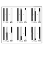
- FIG. 3 shows a “dark (low signal intensity)” systolic image and a “bright (high signal intensity)” diastole image with successive cardiac gating time increments, as shown in FIG. It is the schematic which shows the continuous difference image obtained by the difference between them.
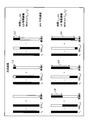
- FIG. 4 is a schematic diagram similar to the schematic diagram of FIG. 3, but includes annotations describing how a standard or average blood flow velocity can be calculated, depending on the embodiment.
- FIG. 5 is a similar schematic showing different images than FIGS.
- FIG. 6 is similar to FIG. 5 but specifically illustrates how the overall standard or average speed can be calculated over a series of different images of the embodiment.
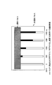
- FIG. 7 shows an outline of velocity measurement according to another embodiment using Time-SLIP (Time-Spatial Labeling Inversion Pulse) imaging method (outflow and tagging / untagged subtraction method).
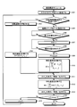
- FIG. 8 is a schematic flowchart regarding an example of a computer program code structure usable in the embodiment.
- FIG. 9 is a schematic diagram of an operator screen that can be used when an operator defines continuous path position points for blood flow along a serpentine path between two consecutive imaging times.
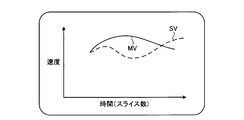
- FIG. 10 is a schematic diagram of an output display graph that can be considered as a specific velocity and / or average velocity for time and / or slice position in an embodiment.
- An MRI (Magnetic Resonance Imaging) system 100 shown in FIG. 1 includes a gantry 10 (shown in a sectional view) and various related system components 20 connected to each other. At least the gantry 10 is usually installed in a shield room.
- One MRI system 100 shown in FIG. 1 has a substantially coaxial cylindrical shape of a static magnetic field B 0 magnet 12, a G x , G y , G z gradient magnetic field coil set 14, and an RF (Radio Frequency) coil assembly 16. Including the arrangement.
- the MRI system control unit 22 includes an input / output port connected to a display unit 24, a keyboard / mouse 26, and a printer 28.
- the display unit 24 may be a diverse touch screen that also includes control inputs.
- the MRI system control unit 22 interfaces with the MRI sequence control unit 30.
- the MRI sequence control unit 30 includes the G x , G y , and G z gradient magnetic field coil drivers 32, and the RF transmission unit 34 and the transmission / reception switch 36 (when the same RF coil is used for both transmission and reception). Are controlled in order.
- the MRI sequence controller 30 includes a program code structure 38 suitable for executing an MRI data acquisition sequence (including imaging of a flowing fluid such as blood) that is already possible in the MRI sequence controller 30.
- the cardiac signal acquisition device 8 for example, an ECG (electrocardiogram) or peripheral vascular pulse transducer (s) appropriately mounted on the body of the subject 9) is used as a trigger signal of the MRI sequence controller 30.
- Signal 13 can be output.
- the MRI system 100 includes an RF receiving unit 40 that supplies an input to the MRI data processing unit 42 so that processed image data to be output to the display unit 24 can be created. Further, the MRI data processing unit 42 may be configured to be able to access the image reconstruction program code structure 44 and the MR image storage unit 46 (for example, from the processing according to the embodiment and the image reconstruction program code structure 44). To store the obtained MRI data).
- FIG. 1 shows a generalized representation of the MRI system program / data storage unit 50.
- the program code structure stored in the MRI system program / data storage 50 (eg, for image reconstruction and for measuring flow velocity, distance / time, operator input, etc.) Stored in a computer readable storage medium accessible to various data processing components.
- the MRI system program / data storage 50 may vary among the processing computers of the MRI system 100 that have an immediate need for the program code structure so stored during normal operation.
- the computer may be divided into simple computers and at least a part thereof may be directly connected (that is, instead of being normally stored in the MRI system control unit 22 or directly connected).
- FIG. 1 is a very high degree of simplification of a typical MRI system 100 with some modifications to allow implementation of the embodiments described later herein.
- FIG. System components can be divided into various logic collection “boxes”, usually with a large number of digital signal processors (DSPs), ultra-compact processors, special purpose processing circuits (eg, high-speed A / D conversion, fast Fourier transform, array processing, etc.).
- DSPs digital signal processors
- ultra-compact processors special purpose processing circuits (eg, high-speed A / D conversion, fast Fourier transform, array processing, etc.).
- Each of these processors is typically a clocked “state machine” that progresses from one physical state to another when each clock cycle (or a predetermined number of clock cycles) occurs. is there.
- the physical state of the processing circuit eg, CPU (Central Processing Unit), registers, buffers, computing units, etc.
- the physical state of a data storage medium eg, the bit storage portion of a magnetic storage medium
- the array of computer readable accessible data value storage locations on the physical storage medium may have several pre-states (eg, all uniform “zero” values or all “1”). Value) to a new state.
- such an array of stored data values represents and also constitutes a physical structure. That is, when sequentially read into the instruction register and executed by one or more CPUs of the MRI system 100, a specific sequence of operating states is generated and the computer control program code transferred into the MRI system 100 A specific structure is constructed.
- the following embodiments provide an improved method for performing data acquisition and / or MR image generation and display, including the velocity of a flowing fluid (hereinafter referred to as “flow rate” where appropriate).
- This change in MR signal intensity can be achieved, for example, by subtracting a systolic image with a low signal value from a diastole image with a high signal value, and a high signal value from a systolic image with a low signal value.
- By subtracting the diastole image or both it can be used to obtain a non-contrast-enhanced flow of fluid (eg, blood) that is time resolved. This is sometimes called time-resolved non-contrast MRA (Magnetic Resonance Angiography).
- Another non-contrast imaging technique for fluid flow is Time-SLIP (Time-Spatial Labeling Inversion Pulse), sometimes called ASL (Arterial Spin Labeling).
- the fluid flow velocity measurement in the non-contrast fluid image can be realized by at least two methods.
- the first is a method using a subtraction image between the diastole and the systole.
- the MRI system 100 can specify the moving distance of the fluid using the subtraction images of the diastole and the systole.
- the path from the start point to the end point can be considered as a simple line.
- the path from the start point to the end point can be specified by connecting points that are effectively placed along the path. It can also be effective to automatically track the distance traveled by the flowing fluid along an arbitrarily formed path.
- the distance that the flowing fluid has passed during successive imaging times is used to calculate a specific velocity during successive imaging times, as well as a standard or average velocity over a series of such imaging times. Can be used.
- the second is a technique using a non-contrast Time-SLIP imaging technique.
- slightly different imaging such as FASE (Fast Asymmetric Spin Echo) or bSSFP (balanced Steady State Free Precession) depending on whether the phase encoding sequence for k-space is centric ordering or sequential ordering A sequence may be included.
- FASE Fluor Asymmetric Spin Echo
- bSSFP balanced Steady State Free Precession
- the time increment used as the denominator in the flow velocity calculation is BBTI (Black-Blood Time to Inversion) time, plus, effective echo time (TEeff).
- BBTI Black-Blood Time to Inversion
- TEeff effective echo time
- BBTI time is plus 1 ⁇ 2 ETL (echo train length) (a time corresponding to half the number of phase encodes).
- Velocity measurement generates flow displacement between different ECG (Electrocardiogram) (ECG gating) signal points (eg systole to diastole) or uses FBI (Fresh Blood Imaging)-Navi signal difference plot This can be done for MR signals. Velocity measurements of flowing MR signal displacements or moved MR signals can be measured.
- ECG Electrocardiogram
- ECG gating Electrocardiogram
- FBI Fluorh Blood Imaging
- the displacement of the MR signal that produces the flow rate using the Time-SLIP imaging technique during BBTI time is also Can be used to calculate average speed.
- a simple GUI can be used to selectively calculate the flow velocity along the travel distance (eg, by pressing a mouse button).
- the distance traveled can be delineated by the user (eg, by defining points that are effectively placed along the path) or by a system-provided auto-tracking function. Regardless, the travel distance is then divided by the time interval associated with that distance (eg, between images subtracted in ECG delay imaging technology and / or Time-SLIP imaging technology).
- GUI can be used to measure flow rate movement of either or both average speed and specific speed.
- velocity measurements can be measured in at least two ways.
- the first method can use a diastole-systole subtraction imaging technique to draw a displacement line along the distance of the MR signal displacement (by the closest point or long connected line).
- the MRI display system automatically records this as a distance and then (for example, subtracted systolic and subtracted) by clicking the appropriate button (or, for example, the correct mouse click for speed selection).
- a calculation is implemented that divides such a distance by the appropriate corresponding time difference (between the effective elapsed times of the diastole images).
- the MRI signal is for Time-SLIP using FASE (BBTI + TEeff), and for Time-SLIP using bSSFP in centric ordering (BBTI), And (BBTI + ETL / 2 for Time-SLIP using bSSFP in sequential ordering) to produce a flow rate that travels from the first signal to the last signal.
- BBTI + TEeff FASE
- BBTI + ETL / 2 Time-SLIP using bSSFP in sequential ordering
- the MRI system 100 includes a collection unit, a specifying unit, an acquisition unit, and a calculation unit.
- the collection unit collects a plurality of fluid images that are images of fluid moving within the subject.
- the specifying unit specifies a moving distance of the fluid using a difference image between a reference image that is one of the plurality of fluid images and each fluid image.
- the acquisition unit acquires the elapsed time corresponding to the movement distance from the pulse sequence information used for collecting a plurality of fluid images.
- the calculation unit calculates the fluid flow velocity by dividing the movement distance by the elapsed time.
- Case 1 for collecting multiple fluid images with different cardiac phases
- Case 2 for collecting multiple fluid images with different temporal phases by Time-SLIP (Time-Spatial Labeling Inversion Pulse) imaging method explain.
- Time-SLIP Time-Spatial Labeling Inversion Pulse
- the collection unit according to Case 1 collects a plurality of fluid images that are images of fluid moving in the subject and have different cardiac phases.
- the specifying unit according to case 1 specifies the moving distance of the fluid using a plurality of fluid images.
- the acquisition unit according to Case 1 acquires the elapsed time corresponding to the movement distance from the pulse sequence information used for collecting a plurality of fluid images.
- the calculation unit according to case 1 calculates the flow velocity of the fluid by dividing the movement distance by the elapsed time.
- these units are provided in the MRI system control unit 22 (not shown), and these units provided in the MRI system control unit 22 are related to the MRI sequence control unit 30, the gantry unit 10, and the like. Control the components.
- the collection unit collects a plurality of fluid images having different cardiac time phases between the systole and the diastole using, for example, the FBI imaging method.
- the FBI imaging method is a blood vessel imaging method by 3D FASE, and an appropriate delay time from a synchronization signal (for example, R wave) is set, and collection is performed using electrocardiogram synchronization or pulse wave synchronization. This is an imaging method to depict new blood to be drawn.
- the brightness of the MR signal collected by the collection unit varies between the systole and the diastole as shown in FIG. Therefore, the collection unit sets delay times t 0 msec, t 1 msec,...
- the delay from the ECG synchronization signal gradually increases, and collects the MR signal S 1 in synchronization with the delay time t 0 msec.
- a plurality of fluid images having different cardiac phases are collected such that the MR signal S 2 is collected in synchronization with a delay time t 1 msec.
- the specifying unit uses, for example, a difference image between a fluid image collected in a predetermined cardiac phase and a fluid image collected in a reference cardiac phase for each fluid image having different cardiac phases. Identify the distance traveled by the fluid. As described above, the MR signal brightness differs between fluid images with different cardiac phases. Therefore, for example, by subtracting the fluid image collected in the predetermined cardiac phase from the fluid image collected in the reference cardiac phase, the fluid (for example, blood) that has moved in the subject during that time The signal can be drawn. For example, in FIG. 3, “t n ” indicates a reference cardiac time phase, and “S1 (t n )” indicates an MR signal collected in the cardiac time phase t n . As shown in FIG.
- Images 1 to 6 are images obtained by subtracting the fluid images of the respective time phases from the fluid images of the cardiac phase as a reference, and are images in which only blood is drawn by subtracting information other than blood.
- the specifying unit analyzes images 1 to 6 which are the difference images based on the luminance, and distinguishes between the high luminance portion and the low luminance portion, for example, to move the fluid in each cardiac phase. Identify the distance.
- the specifying unit specifies the movement distances L2 to L6 as shown in FIG.
- the acquisition unit acquires the elapsed time from the pulse sequence information for each moving distance of each fluid image. For example, in case 1, the elapsed time corresponding to each cardiac time phase corresponds to a delay time set as pulse sequence information. For this reason, an acquisition part acquires the delay time set as pulse sequence information. For example, as illustrated in FIG. 4, the acquisition unit acquires t n + 1 msec, t n + 2 msec, t n + 3 msec, t n + 4 msec, and t n + 5 msec as delay times.
- a calculation part calculates a flow velocity, for example using each moving distance and each elapsed time.
- the calculation unit calculates the flow velocity by dividing the accumulated moving distance obtained by accumulating the moving distances by the accumulated elapsed time obtained by accumulating the elapsed times.
- the calculation unit calculates the speed by dividing the accumulated movement distance L6 accumulated in each cardiac time phase by the accumulated elapsed time (t n + 5 ⁇ t n ).
- the speed calculation method is not limited to this.
- the calculation unit may calculate a specific speed specific to the cardiac phase by dividing a certain moving distance by an elapsed time corresponding to the moving distance. For example, as illustrated in FIG.
- the calculation unit calculates the average speed MV3 by dividing the movement distance L3 by the elapsed time (t n + 2 ⁇ t n ). For example, as illustrated in FIG. 5, the calculation unit divides the moving distance ⁇ L6 that is the difference between the image 6 and the image 5 by the elapsed time (t n + 5 ⁇ t n + 4 ), so that the specific speed SV (Specific Velocity) may be calculated.
- the collection unit according to case 2 performs labeling on the spin of the fluid moving in the subject, and receives the echo signal of the spin after a predetermined time, and performs imaging a plurality of times at different predetermined times to obtain an image of the fluid A plurality of fluid images having different time phases are collected.
- the specifying unit according to case 2 specifies the moving distance of the fluid using a plurality of fluid images.
- the acquisition unit according to Case 2 acquires the elapsed time corresponding to the movement distance from the pulse sequence information used for collecting the fluid image.
- the calculation unit according to Case 2 calculates the flow velocity of the fluid by dividing the movement distance by the elapsed time.
- these units are provided in the MRI system control unit 22 (not shown), and these units provided in the MRI system control unit 22 are related to the MRI sequence control unit 30, the gantry unit 10, and the like. Control the components.
- the collection unit collects a plurality of fluid images having different time phases using, for example, the Time-SLIP imaging method.
- the Time-SLIP imaging method the fluid flowing into or out of the imaging area is labeled (labeled) at a position independent of the imaging area, and the signal value of the fluid flowing into or out of the imaging area is increased or decreased.
- it is an imaging method for depicting a fluid.
- a Time-SLIP pulse is applied after a certain waiting time from a synchronization signal (for example, R wave).
- This Time-SLIP pulse includes a region non-selection inversion pulse (“non-selection pulse” in FIG. 7) and a region selection inversion pulse (“selection pulse” in FIG.
- the collection unit sets a plurality of BBTI times and collects a plurality of fluid images having different time phases.
- the labeling position when the labeling position is set outside the imaging region, the labeled fluid flows into the imaging region, and is referred to as “flow-in” here.
- the labeled fluid flows out to the imaging region, and this is referred to as “flow out” here.
- the embodiment can be applied to both “flow-in” and “flow-out”.
- the collection unit according to Case 2 repeats, for example, two fluids by alternately performing collection in which labeling is performed using a region selection inversion pulse and collection in which labeling is not performed using a region selection inversion pulse for each slice encoding. Collect images. Note that collection without labeling may be performed once, for example, without being performed every slice encoding. Furthermore, the embodiment can be applied to a case where collection without labeling is not performed.
- the specific part which concerns on case 2 uses the difference image of the reference
- the fluid from which a time phase differs
- the moving distance of the fluid is specified for each image.
- the specifying unit extracts only the labeled portion by taking the difference between two fluid images collected for the same slice encoding, and suppresses the background signal.
- the specifying unit performs the labeling by taking the difference between the reference image collected at this time and each fluid image collected by the imaging that performs labeling. The extracted part is extracted and the background signal is suppressed. Then, as shown in FIG.
- the specifying unit analyzes each fluid image based on the luminance, and specifies the moving distance of the fluid in each time phase by, for example, distinguishing a portion with high luminance from a portion with low luminance.
- the acquisition unit acquires the elapsed time from the pulse sequence information for each moving distance of each fluid image. For example, in case 2, it is assumed that the collecting unit collects a plurality of fluid images having different time phases by the Time-SLIP imaging method using the FASE (Fast Asymmetric Spin Echo) method. In this case, the acquisition unit acquires a value obtained by adding the BBTI time and the effective echo time (TEeff (Effective Time to Echo)) from the pulse sequence information as the elapsed time.
- TEeff Effective Echo
- the acquisition unit according to Case 2 may acquire the elapsed time corresponding to the moving distance according to the k-space filling method used for generating the fluid image.
- the collection unit collects multiple fluid images with different time phases by Time-SLIP imaging method using bSSFP (balanced Steady State Free Precession) method.
- bSSFP balanced Steady State Free Precession
- the acquisition unit is a value obtained by adding, as elapsed time, BBTI time and a time corresponding to half the number of phase encodes from pulse sequence information. To get. These elapsed times are intended to correspond to the elapsed time at which MR signals filled near the center of k-space were collected.
- the calculation unit calculates the flow velocity by dividing the accumulated moving distance obtained by accumulating each moving distance by the accumulated elapsed time obtained by accumulating each elapsed time, for example, as in Case 1.
- the labeling method may be, for example, a pCASL (Pulsed Continuous Arterial Spin Labeling) method of continuously irradiating a labeling pulse.
- pCASL Pulsed Continuous Arterial Spin Labeling
- the width and size of the labeling region (labeling region) may be set thick.
- case 1 and case 2 preferably all calculations are preferably performed by selecting the icon of “speed” (both or one of “average speed” and “specific speed”) by mouse click, for example. This is done on the MR image console.
- non-contrast Time-SLIP (ASL) technology observes flow fluid by using multiple different BBTI times in an MRI sequence.
- the FBI / Navi routine or the like obtains continuous slice images S1, S2, S3 ⁇ in a continuous delay time from a systole to a diastole of a general PQRSTU heart cycle.
- Available to: One complete cardiac cycle is sometimes referred to as an “RR” cycle.
- the frequency of the R heart pulse is comparable to the pulse rate of the subject.
- the “FBI / Navi routine” is a function for obtaining a delay time suitable for FBI imaging from an image collected by ECG-Prep imaging.
- the ECG-Prep imaging is a 2D FASE imaging performed prior to imaging by the FBI imaging method in order to set a delay time in the FBI imaging method.
- ECG-Prep imaging multiple images with different cardiac phases are collected while changing the delay time from the synchronization signal (for example, R wave), and analyzed based on the collected multiple images or multiple images
- the signal value transition is displayed on the display unit.
- FBI-Navi analyzes a plurality of images collected by ECG-Prep imaging to extract a region having a large change in signal value, and obtains a difference in signal value between the reference image and each image with respect to the extracted region. The obtained signal value difference is displayed in a graph.
- Cardiac (or peripheral vascular pulse) gating can be used appropriately to subject the subject to MRI sequences at successive delay points of the cardiac cycle. While measuring the systolic at t 0, it depicts the delay increment to the slice S1 for each successive, S2 ⁇ Sn (max), in Figure 2 up to the time at t n (max).
- the systolic image having the minimum signal intensity is generally subtracted from the diastole image having the maximum signal intensity, thereby obtaining a single MRA image.
- FIG. 3 is a schematic diagram of an idealized fully linear artery.
- the artery is imaged at time t 0 during systole and then continuously again at time intervals that increase incrementally toward diastole at t n + 1 , t n + 2, etc.
- the resulting series of images starts with a null image 1 (since two identical images are subtracted), and then progresses, so that the MR signal in which the fluid in flow is constantly increasing as the imaging time approaches closer to diastole
- the luminance is generated, the fluid flowing in the imaged arterial portion starting from the top and moving toward the bottom becomes apparent (FIG. 3).
- the leading edge of the flowing fluid can be identified through various lengths of arteries, starting at time t n and through various successive time intervals.
- the total length of the distance traveled by the flowing fluid can be measured, and at the end of each imaging interval, by dividing the total length by the elapsed time, the average Speed can be measured.
- the specific speed for each incremental time interval between images can also be calculated by calculating the incremental distance moved between images and dividing by the appropriate associated time interval. Assuming that the time intervals between images are equal, the specific speed increases in image 3 compared to image 2 and further increases in image 4 compared to image 3, as can be seen from FIG. However, the specific speed clearly decreases in image 5 compared to image 4 and then increases again in image 6 compared to image 5.
- consecutive images 1-6 in the same set can also be analyzed (comparing image 6 with image 1) to calculate only the standard or average speed over the entire interval.
- non-contrast time-resolved MRA can now include flow velocity measurements, using diastole-systole images, as shown in the video mode.
- the length of the moved blood vessel part is divided by the time required for the movement, thereby obtaining a velocity (interval or smaller interval group).
- Standard speed over a series of intervals and / or a series of specific speeds, or average speed That is, a standard value of a specific speed that gradually increases from one section to the next section provides an average or standard speed over a longer time that encompasses the entire image.
- FIG. 7 schematically depicts Time-SLIP non-contrast imaging of fluid flow rate.
- the selection pulse and the non-selection pulse are represented by rectangles having different sizes.
- an artery similar to successive images at different time increments described in the previous figure for different images of diastole-systole A continuous image of fluid flow in a vein or the like can be obtained.
- measurement of distance traveled along arteries, veins, etc., and division by associated travel time can also make velocity measurements using this non-contrast flow imaging technique.
- FIG. 8 schematically depicts a speed measurement module with a computer program code structure.
- This module can be any suitable means related to the main or surveillance operating system etc. (eg, mouse clicks on suitably displayed icons or menus by the operator, finger input on touch screen, keyboard By using input).
- step S01 the slice counter n is initialized to a value of 1.
- step S02 have options set for an automatic tracking system for distance measurement (eg by setting control parameters in the basic settings dialog etc. to use the distance tracking algorithm automatically executed by the machine)? Do a test to see if it is no. If set, then the auto-tracking function operates at step S03, the specific speed SV, in step S04, is calculated between the acquired slices in a subsequent t n and t n-1 .
- step S05 the route counter P is initialized to a value of 1 in step S05.
- step S06 a standby loop is executed for the operator to define the first position. For example, as shown in FIG. 9, the operator moves the cursor over the first point P1 (related to the imaging time t n ⁇ 1 ) and clicks a predetermined mouse button to select an artery or the like.
- a first position on the fluid flow rate display image can be defined.
- a pop-up menu 93 may also be provided that allows the operator to select a specially defined point to identify an initial path position, an intermediate path position, or a final path position. For example, as shown in FIG.
- operator-defined points P1 to P5 are defined as effective points along a meandering blood vessel (between imaging times t n ⁇ 1 and t n ).
- the straight line portion between the distinct points along the flow path closely approximates the flow distance from the slice image Sn-1 to the slice image Sn.
- step S11 the specific speed SV (no matter how it is calculated) associated with the final time t n is displayed and stored in step S11 or (for example, a remote location as desired configured in a preferred part of the system) Output).
- step S12 the moving average speed MV is calculated in step S12 and similarly displayed in step S13, stored, or output as desired (eg, as previously configured in the system).
- step S14 a test is performed to see whether or not the slice counter has reached the final value (ie, slice Sn (max)). If not, then the slice counter is incremented in step S15 and control is returned to decision step S02 as shown in FIG. 8, or directly to re-initialization of the path counter in block step S06 ( Ie if the operator does not want to activate the automatic tracking system).
- the module ends as shown in FIG.
- both or one of the specific speed SV and the moving average speed MV can be displayed as a graph as a function of time (or the number of slices, etc.).
- the MRI system 100 includes a display control unit that displays information on the flow rate on at least one of the fluid image and the reference image that is the target of the difference processing with the fluid image. Further, it may be provided.
- the display control unit is provided in the MRI system control unit 22 (not shown), and the display control unit provided in the MRI system control unit 22 controls related components.
- the fluid image collected by the collection unit is, for example, a fluid image collected by the FBI imaging method or a fluid image collected by the Time-SLIP imaging method, and can be said to be an image with high resolution. Since the MRI system 100 according to the embodiment calculates the “fluid velocity” as the function information from the high-resolution morphological image itself, the morphological image and the calculation basis of the functional information match. .
- the display control unit may display the morphological image while superimposing the fluid velocity information on the morphological image.
- the display control unit displays on the morphological image depicting the blood vessels of the lower limbs that the flow velocity exists at the location where the flow velocity exists (for example, the blood vessel of the lower limb is filled), and the location where the flow velocity does not exist May be displayed indicating that there is no flow velocity (for example, slanting the blood vessels of the lower limbs).
- the display control unit displays the 3D morphological image while superimposing and displaying the fluid video data in 2D on the 3D morphological image (for example, the image 1 to the image illustrated in FIG. 3). 6 may be continuously reproduced and displayed on the display unit).
- the flow velocity of the fluid can be obtained.
Landscapes
- Health & Medical Sciences (AREA)
- Physics & Mathematics (AREA)
- Life Sciences & Earth Sciences (AREA)
- Nuclear Medicine, Radiotherapy & Molecular Imaging (AREA)
- High Energy & Nuclear Physics (AREA)
- Engineering & Computer Science (AREA)
- General Health & Medical Sciences (AREA)
- Radiology & Medical Imaging (AREA)
- Condensed Matter Physics & Semiconductors (AREA)
- General Physics & Mathematics (AREA)
- Medical Informatics (AREA)
- Surgery (AREA)
- Veterinary Medicine (AREA)
- Public Health (AREA)
- Animal Behavior & Ethology (AREA)
- Molecular Biology (AREA)
- Heart & Thoracic Surgery (AREA)
- Biophysics (AREA)
- Pathology (AREA)
- Biomedical Technology (AREA)
- Spectroscopy & Molecular Physics (AREA)
- Optics & Photonics (AREA)
- Vascular Medicine (AREA)
- Signal Processing (AREA)
- Physiology (AREA)
- Cardiology (AREA)
- Hematology (AREA)
- Magnetic Resonance Imaging Apparatus (AREA)
Abstract
実施形態に係る磁気共鳴イメージング装置(100)は、収集部(22)と、特定部(22)と、取得部(22)と、算出部(22)とを備える。前記収集部(22)は、被検体内を移動する流体の画像である流体画像を複数収集する。前記特定部(22)は、前記複数の流体画像のうちの1つである基準画像と各流体画像との差分画像を用いて、前記流体の移動距離を特定する。前記取得部(22)は、前記移動距離に対応する経過時間を、前記複数の流体画像の収集に用いられたパルスシーケンス情報から取得する。前記算出部(22)は、前記移動距離を前記経過時間で除算することで前記流体の流速を算出する。
Description
本発明の実施形態は、磁気共鳴イメージング装置及び磁気共鳴イメージング方法に関する。
従来、磁気共鳴イメージング装置(以下、MRI(Magnetic Resonance Imaging)システム)による撮像法のひとつに、造影剤を用いずに被検体内を移動する流体を撮像する手法がある。
Miyazaki, et al., "Non-contrast-enhanced MR angiography using 3D ECG-synchronized half-Fourier fast spin echo," JMRI 12:776-783 (2000)
Suga, et al., Lung perfusion impairments in pulmonary embolic and airway obstruction with non contrast MR imaging," J Appl Physiol92:2439-2451 (2002)
Takahashi, et al., "Non-contrast-enhanced renal MRA using time-spatial labeling pulse(t-SLIP) with 3D balanced SSFP," presented at the ISMRM 15th Annual Meeting, Berlin, Germany, page 179(2007)
Yamamoto, et al., "Non-contrast-enhanced MRDSM of peripheral arteries using continuous acquisitions of ECG-triggered 2D half-Fourier FSE within a cardiac cycle," 12th Annual Meeting, Toronto, Canada, page 1709(2003)
Kanazawa, et al., "Time-spatial labeling inversion tag (t-SLIT) using a selective IR-tag on/off pulse in 2D and 3D half-Fourier FSE as arterial spin labeling," presented at the ISMRM 10th Annual Meeting, Hawaii, page 140(2002)
Furudate, et al., "FBI-Navifor Easy Determination of Diastolic and Systolic Triggering Phase in Non-Contrast Fresh Blood Imaging(FBI)," ISMRM 16th Annual Meeting, Toronto, Canada, page 2902(2008)
本発明が解決しようとする課題は、流体の流速を求めることである。
実施形態に係る磁気共鳴イメージング装置は、収集部と、特定部と、取得部と、算出部とを備える。前記収集部は、被検体内を移動する流体の画像である流体画像を複数収集する。前記特定部は、前記複数の流体画像のうちの1つである基準画像と各流体画像との差分画像を用いて、前記流体の移動距離を特定する。前記取得部は、前記移動距離に対応する経過時間を、前記複数の流体画像の収集に用いられたパルスシーケンス情報から取得する。前記算出部は、前記移動距離を前記経過時間で除算することで前記流体の流速を算出する。
図1に示すMRI(Magnetic Resonance Imaging)システム100は、架台部10(断面図にて示す)と、互いに接続される様々な関連のシステム構成要素20とを含む。少なくとも架台部10は、通常シールドルーム内に設置される。図1に示す1つのMRIシステム100は、静磁場B0磁石12と、Gx、Gy、Gz傾斜磁場コイルセット14と、RF(Radio Frequency)コイルアセンブリ16との実質的に同軸円筒状の配置を含む。この円筒状に配置された要素の水平軸線に沿って、被検体テーブル11によって支持された被検体9の頭部を取り囲むように示された撮像ボリューム18がある。
MRIシステム制御部22は、表示部24、キーボード/マウス26、及びプリンタ28に接続された入力/出力ポートを備える。言うまでもなく、表示部24は、制御入力もまた備えるような多様性のあるタッチスクリーンであってもよい。
MRIシステム制御部22は、MRIシーケンス制御部30とインタフェース接続する。MRIシーケンス制御部30は、Gx、Gy、Gz傾斜磁場コイルドライバ32、並びに、RF送信部34及び送信/受信スイッチ36(同じRFコイルが送信及び受信の両方に使用されている場合)を順に制御する。MRIシーケンス制御部30は、既にMRIシーケンス制御部30にて可能な、MRIデータ取得シーケンス(血液等の流動する流体(flowing fluid)の撮像を含む)の実行に適切なプログラムコード構造38を含む。心臓信号取得装置8(例えば、被検体9の身体に適切に装着された、ECG(electrocardiogram)又は末梢血管パルストランスデューサ(単数又は複数))は、MRIシーケンス制御部30のトリガー信号とする心電ゲート信号13を出力することができる。
MRIシステム100は、表示部24に出力する処理された画像データを作成できるように、MRIデータ処理部42に入力を供給するRF受信部40を含む。また、MRIデータ処理部42を、画像再構成プログラムコード構造44及びMR画像記憶部46にアクセスできるように構成してもよい(例えば、実施形態及び画像再構成プログラムコード構造44に従った処理から得られたMRIデータを格納するために)。
また、図1は、MRIシステムプログラム/データ格納部50を一般化した描写を示す。MRIシステムプログラム/データ格納部50に格納されるプログラムコード構造(例えば、画像再構成のため、及び、流速、距離/時間の測定のため、操作者入力等のための)は、MRIシステム100の様々なデータ処理構成要素にアクセス可能なコンピュータ読み取り可能な記憶媒体に格納される。当業者には自明であるが、MRIシステムプログラム/データ格納部50は、正常運転時にそのように格納されたプログラムコード構造に対して直近の必要性を有するMRIシステム100の処理コンピュータのうちの様々なコンピュータに分割し、且つ少なくとも一部を直結してもよい(すなわち、MRIシステム制御部22に普通に格納したり、直結したりする代わりに)。
実際、当業者には自明であるが、図1の描写は、本明細書で後述する実施形態を実行できるように若干の変更を加えた一般的なMRIシステム100を非常に高度に簡素化した図である。システム構成要素は、様々な論理収集の「ボックス」に分割でき、通常、多数のデジタル信号処理装置(DSP(Digital Signal Processors))、超小型演算処理装置、特殊用途向け処理回路(例えば、高速A/D変換、高速フーリエ変換、アレイ処理用等)を含む。これら処理装置のそれぞれは、通常、各クロックサイクル(又は所定数のクロックサイクル)が発生すると、物理データ処理回路がある物理的状態から別の物理的状態へ進むクロック動作型の「状態機械」である。
動作中に、処理回路(例えば、CPU(Central Processing Unit)、レジスタ、バッファ、計算ユニット等)の物理的状態が、あるクロックサイクルから別のクロックサイクルへ漸進的に変化するだけでなく、連結されているデータ格納媒体(例えば、磁気記憶媒体のビット格納部)の物理的状態も、そのようなシステムの動作中に、ある状態から別の状態へ変わる。例えば、MRI再構成プロセスの終了時、物理的記憶媒体のコンピュータ読み取り可能なアクセス可能データ値格納場所のアレイは、いくつかの事前の状態(例えば、全部一律の「ゼロ」値又は全部「1」値)から新しい状態に変わる。その新しい状態では、そのようなアレイの物理的場所の物理的状態は、最小値と最大値との間で変動し、現実世界の物理的事象及び状況(例えば、撮像ボリューム空間内の被検体の動脈内を流れる血液)を表現する。当業者には自明であるが、格納されたデータ値のそのようなアレイは、物理的構造を表し且つ構成もする。つまり、命令レジスタの中に順次読み込まれてMRIシステム100の1つ以上のCPUによって実行されたとき、動作状態の特定シーケンスが発生して、MRIシステム100内中に移行されるコンピュータ制御プログラムコードの特定構造が構成される。
下記の実施形態は、流動する流体の速度(以下、適宜「流速」という)を含む、データ取得の処理及びMR画像の生成表示の両方又は一方を行うための改良された方法を提供する。
心収縮期及び心拡張期のタイミングと同期して収集された画像間には、MR信号強度の変化がある。このMR信号強度の変化は、例えば、信号値の高い心拡張期の画像から信号値の低い心収縮期の画像を減算すること、及び、信号値の低い心収縮期の画像から信号値の高い心拡張期の画像を減算することの両方あるいは一方を行うことによって、時間分解された流体(例えば、血液)の流れを非造影にて得るために用いることができる。これは、時間分解非造影MRA(磁気共鳴血管造影法(Magnetic Resonance Angiography))と呼ばれることもある。また、流体の流れのための他の非造影撮像技術として、ASL(Arterial Spin Labeling)と呼ばれることもあるTime-SLIP(Time-Spatial Labeling Inversion Pulse)がある。
これらの非造影撮像技術においては、流体の流速測定を容易にするための操作者インタフェースが、望まれるであろう。
以下に示す実施形態によれば、非造影の流体画像における流体の流速測定は、少なくとも2つの手法で実現することができる。第1は、心拡張期と心収縮期との減算画像を用いる手法である。MRIシステム100は、心拡張期と心収縮期との減算画像を用いて、流体の移動距離を特定することができる。例えば、動脈経路が比較的線形である場合、開始ポイントから最終ポイントまでの経路を単純な線であると考えることができる。あるいは、動脈経路が蛇行状の場合でも、経路に沿って効果的に置かれたポイントをつなぐことによって、開始ポイントから最終ポイントまでの経路を特定することができる。任意に形成された経路に沿って流動中の流体が移動した距離を自動的に追跡することも有効であるといえる。とにかく、流動中の流体が連続する撮像時間の間に通過した距離は、連続する撮像時間の間の特定の速度、並びに、一連のそのような撮像時間にわたる標準又は平均の速度を算出するために使用することができる。
第2は、非造影Time-SLIP撮像技術を使用する手法である。非造影Time-SLIP撮像技術を使用する場合、k空間に対する位相エンコードの配列がセントリックオーダリングかシーケンシャルオーダリングかによって、FASE(Fast Asymmetric Spin Echo)又はbSSFP(balanced Steady State Free Precession)などの若干異なる撮像シーケンスを含んでもよい。もちろん、流速の計算において分子は、やはり、信号を発生して流れる物質(例えば、血液)が移動した距離である。流速の計算において分母として使用される時間増分は、FASE撮像法を用いたTime-SLIPの場合、BBTI(Black-Blood Time to Inversion)時間、プラス、実効エコー時間(TEeff)である。また、セントリックオーダリングでbSSFPを用いたTime-SLIPの場合、BBTIである。また、シーケンシャルオーダリングでbSSFPを用いたTime-SLIPの場合、BBTI時間、プラス、1/2ETL(エコートレイン長)(位相エンコード数の半数分に相当する時間)である。
速度測定は、異なるECG(Electrocardiogram)(心電図ゲーティング)信号ポイント(例えば、心収縮期から心拡張期)間に流量変位を生成する、又は、FBI(Fresh Blood Imaging)-Navi信号差プロットを使用するMR信号に対して行うことができる。流動するMR信号変位又は移動したMR信号の速度測定を計測できる。
上述のように、(k空間配列に依存してTEeff及びETL/2の両方又は一方をおそらくプラスする)BBTI時間の間にTime-SLIP撮像技術を使って流量を生成するMR信号の変位もまた、平均速度の計算に使用できる。
一実施形態では、移動距離に沿った流速を選択的に計算するために(例えば、マウスボタンの押下によって)、簡単なGUI(Graphical User Interface)を使用できる。移動距離は、ユーザーによって(例えば、経路に沿って効果的に置かれたポイントを画定することによって)、又は、システム提供の自動追跡機能によって、輪郭を描出できる。とにかく、移動距離は、次に、(例えば、ECG遅延撮像技術及びTime-SLIP撮像技術の両方又は一方において減算された画像間の)その距離に関連する時間間隔によって除算される。
GUIは、平均速度及び特定速度の両方又は一方の流量移動の測定に使用できる。非造影技術では、速度測定は、少なくとも2つの方法で測定できる。第1の方法は、心拡張期-心収縮期減算撮像技術を使って、MR信号変位(最も近いポイント又は長く連結された線による)の距離に沿って変位線を描くことができる。MRI表示システムは、自動的にこれを距離として記録して、次に、適切なボタンのクリック(又は、例えば、速度選択のための正しいマウスクリック)によって、(例えば、減算される心収縮期及び心拡張期の画像の有効経過時間の間の)適切な対応する時間差によってそのような距離を除算する計算を実現する。第2の方法(例えば、ASL(arterial spin labeling)法)では、MRI信号は、FASEを用いたTime-SLIPに対する(BBTI+TEeff)、及びセントリックオーダリングでbSSFPを用いたTime-SLIPに対する(BBTI)、及び(シーケンシャルオーダリングでbSSFPを用いたTime-SLIPに対するBBTI+ETL/2)によって除算された距離内で、最初の信号から最後の信号まで移動する流量を生成する。
さて、上述してきた実施形態に係るMRIシステム100を改めて説明すると、実施形態に係るMRIシステム100は、収集部と、特定部と、取得部と、算出部とを備える。収集部は、被検体内を移動する流体の画像である流体画像を複数収集する。特定部は、複数の流体画像のうちの1つである基準画像と各流体画像との差分画像を用いて、流体の移動距離を特定する。取得部は、移動距離に対応する経過時間を、複数の流体画像の収集に用いられたパルスシーケンス情報から取得する。算出部は、移動距離を経過時間で除算することで流体の流速を算出する。例えば、これらの部は、MRIシステム制御部22内に備えられ(図示を省略)、MRIシステム制御部22内に備えられたこれらの部が、MRIシーケンス制御部30や架台部10、その他関連する構成要素を制御する。以下、更にケースに分けて説明する。具体的には、心時相の異なる複数の流体画像を収集するケース1、及び、Time-SLIP(Time-Spatial Labeling Inversion Pulse)撮像法によって時相の異なる複数の流体画像を収集するケース2を説明する。
なお、以下では、実施形態の例としていくつかのケースを説明するが、以下のケースに限定されるものではない。
[ケース1]
まず、ケース1の場合について説明する。
●FASE(Fast Asymmetric Spin Echo)(又はFBI(Fresh Blood Imaging))シーケンスを使用する。位相エンコード(PE)方向が、末梢血管流量に対して垂直である場合、(1RR~nRRsなど)それらの間の小さい増分を伴う各FASE画像のMR信号輝度は、図2に示すように変動する。
●(例えば、心収縮期画像の)低輝度信号を(例えば、心拡張期起動期画像の)高輝度信号から減算すると、図3に示すように、移動する物体のように見える流動ボリュームの合成画像を得る。
●映像で表示した場合、非造影時間分解MRAを見ることができる。更に、蛇行状の血管に沿ってMR流量信号を追跡することによって、画像間の時間差によって除算された移動血管長から速度が得られる。特定の(増分)流量速度v1、v2~vnの平均値から平均流量速度(もちろん、あらゆる中間の特定速度の計算を省略したい場合は、直接計算することもできる)が得られる。
ケース1に係る収集部は、被検体内を移動する流体の画像であって心時相の異なる複数の流体画像を収集する。ケース1に係る特定部は、複数の流体画像を用いて流体の移動距離を特定する。ケース1に係る取得部は、移動距離に対応する経過時間を、複数の流体画像の収集に用いられたパルスシーケンス情報から取得する。ケース1に係る算出部は、移動距離を経過時間で除算することで流体の流速を算出する。例えば、これらの部は、MRIシステム制御部22内に備えられ(図示を省略)、MRIシステム制御部22内に備えられたこれらの部が、MRIシーケンス制御部30や架台部10、その他関連する構成要素を制御する。
収集部は、例えばFBI撮像法を用いて、心収縮期と心拡張期との間にて心時相の異なる複数の流体画像を収集する。FBI撮像法は、3D FASEによる血管撮像法であり、同期信号(例えばR波)からの適切な遅延時間を設定し、心電同期又は脈波同期を用いて収集を行うことで、心臓から拍出される新しい血液を描出する撮像法である。収集部によって収集されるMR信号の輝度は、心収縮期と心拡張期との間で図2に示すように変動する。そこで、収集部は、心電同期信号からの遅延が徐々に増える遅延時間t0msec、t1msec、・・・を設定し、遅延時間t0msecで同期してMR信号S1を収集し、遅延時間t1msecで同期してMR信号S2を収集するというように、心時相の異なる複数の流体画像を収集する。
特定部は、例えば、所定の心時相にて収集された流体画像と、基準となる心時相にて収集された流体画像との差分画像を用いて、心時相の異なる流体画像毎に、流体の移動距離を特定する。上述したように、心時相の異なる流体画像間ではMR信号の輝度が異なる。このため、例えば、基準となる心時相にて収集された流体画像から所定の心時相にて収集された流体画像を減算することで、その間に被検体内を移動した流体(例えば血液)の信号を描出することができる。例えば、図3において、「tn」は基準の心時相を示し、「S1(tn)」は心時相tnにて収集されたMR信号を示す。図3に示すように、例えば、心収縮期にて心臓から拍出された血液のMR信号は、その輝度が低いので(図3において例えば白色で表現)、遅延時間の増分が大きくなるほど、徐々に輝度の低い部分が増える。画像1~画像6は、基準となる心時相の流体画像から各時相の流体画像を差し引いた画像であり、血液以外の情報が差し引かれ、血液のみが描出された画像となる。特定部は、例えば、この差分画像である画像1~画像6を輝度に基づいて解析し、例えば、輝度の高い部分と輝度の低い部分とを区別することで、各心時相における流体の移動距離を特定する。例えば、特定部は、図4に示すように、移動距離L2~L6を特定する。
取得部は、例えば、各流体画像の移動距離毎に、経過時間をパルスシーケンス情報から取得する。例えば、ケース1において、各心時相に対応する経過時間は、パルスシーケンス情報として設定された遅延時間に相当する。このため、取得部は、パルスシーケンス情報として設定された遅延時間を取得する。例えば、取得部は、図4に示すように、遅延時間として、tn+1msec、tn+2msec、tn+3msec、tn+4msec、tn+5msecを取得する。
そして、算出部は、例えば、各移動距離及び各経過時間を用いて流速を算出する。例えば、算出部は、各移動距離を累積した累積異動距離を、各経過時間を累積した累積経過時間で除算することで、流速を算出する。例えば、算出部は、図6に示すように、各心時相で累積した累積移動距離L6を累積経過時間(tn+5-tn)で除算することで速度を算出する。なお、速度の算出手法はこれに限られるものではない。算出部は、ある移動距離を、この移動距離に対応する経過時間で除算することで、その心時相に特定の特定速度を算出してもよい。例えば、図4に示すように、算出部は、移動距離L3を、経過時間(tn+2-tn)で除算することで、平均速度MV3を算出する。例えば、図5に示すように、算出部は、画像6と画像5との差分である移動距離ΔL6を、経過時間(tn+5-tn+4)で除算することで、特定速度SV(Specific Velocity)を算出してもよい。
[ケース2]
続いて、ケース2の場合について説明する。
●流出(非選択及び選択パルス)又は流入(選択パルスのみ)Time-SLIP、並びに、別の取得及び減算(タグ付け及びタグ付けなし減算)もまた、平均速度の測定を可能にする。
○シングルショットFSE(FASE)を使用する場合、速度は、流量移動時間としてのBBTI時間(取得パルスにタグ付けする)及び有効TE(TEeff)内に移動した流量ボリュームを使って計算できる。したがって、速度は、(BBTI+TEeff)によって除算された移動流体の長さ(L)として計算できる。
○bSSFPを使用する場合、速度は、流量移動時間としてのBBTI時間(取得パルスにタグ付けする)内に移動した流量を使って計算できる。したがって、速度は、BBTIで除算された移動流体の長さ(L)として計算できる。
ケース2に係る収集部は、被検体内を移動する流体のスピンに標識化を行い、所定時間経過後にスピンのエコー信号を受信する撮像を、所定時間を異ならせて複数回行い、流体の画像であって時相の異なる複数の流体画像を収集する。ケース2に係る特定部は、複数の流体画像を用いて、流体の移動距離を特定する。ケース2に係る取得部は、移動距離に対応する経過時間を、流体画像の収集に用いられたパルスシーケンス情報から取得する。ケース2に係る算出部は、移動距離を経過時間で除算することで流体の流速を算出する。例えば、これらの部は、MRIシステム制御部22内に備えられ(図示を省略)、MRIシステム制御部22内に備えられたこれらの部が、MRIシーケンス制御部30や架台部10、その他関連する構成要素を制御する。
ケース2の場合、収集部は、例えばTime-SLIP撮像法を用いて、時相の異なる複数の流体画像を収集する。Time-SLIP撮像法は、撮像領域に流入又は流出する流体を、この撮像領域とは独立した位置でラベリング(標識化)し、撮像領域に流入又は流出する流体の信号値を高く又は低くすることで、流体を描出する撮像法である。Time-SLIP撮像法においては、同期信号(例えばR波)から一定の待ち時間後にTime-SLIPパルスを印加する。このTime-SLIPパルスは、領域非選択インバージョンパルス(図7において「非選択パルス」)及び領域選択インバージョンパルス(図7において「選択パルス」)を含み、領域非選択インバージョンパルスは、オン又はオフを設定することができる。領域選択インバージョンパルスによって撮像領域に流入(又は流出)する流体をラベリングすると、BBTI(Black-Blood Time to Inversion)時間後に流体が到達した部分の信号の輝度が高く(領域非選択インバージョンパルスがオフの場合は低く)なる。そこで、収集部は、BBTI時間を複数設定し、時相の異なる複数の流体画像を収集する。
なお、ラベリング位置が撮像領域外に設定された場合、ラベリングされた流体は撮像領域に流入するので、ここではこれを「フローイン」と呼ぶ。一方、ラベリング位置が撮像領域内に設定された場合、ラベリングされた流体は撮像領域に流出するので、ここではこれを「フローアウト」と呼ぶ。実施形態は、「フローイン」及び「フローアウト」のいずれにも適用することができる。
ここで、ケース2に係る収集部は、領域選択インバージョンパルスによってラベリングを行う収集と、領域選択インバージョンパルスによってラベリングを行わない収集とを、例えばスライスエンコード毎に交互に繰り返すことで2つの流体画像を収集する。なお、ラベリングを行わない収集については、スライスエンコード毎に毎回行わず、例えば1回行うものとしてもよい。更に、実施形態は、ラベリングを行わない収集を行わない場合にも、適用することができる。
そして、ケース2に係る特定部は、ラベリングを行わない撮像により収集された画像である基準画像と、ラベリングを行う撮像により収集された各流体画像との差分画像を用いて、時相の異なる流体画像毎に、流体の移動距離を特定する。例えば、特定部は、同一スライスエンコードについて収集された2つの流体画像間の差分をとることで、ラベリングされた部分のみを抽出し、背景信号を抑制する。あるいは、ラベリングを行わない収集が1回である場合は、特定部は、この1回に収集された基準画像と、ラベリングを行う撮像により収集された各流体画像との差分をとることで、ラベリングされた部分のみを抽出し、背景信号を抑制する。すると、図7に示すように、差分画像において、BBTI時間の増分が大きくなるほど、徐々に輝度の高い部分が増える(図7において例えば黒色で表現)。特定部は、例えば、各流体画像を輝度に基づいて解析し、例えば、輝度の高い部分と輝度の低い部分とを区別することで、各時相における流体の移動距離を特定する。
取得部は、各流体画像の移動距離毎に、経過時間をパルスシーケンス情報から取得する。例えば、ケース2において、収集部が、FASE(Fast Asymmetric Spin Echo)法を用いたTime-SLIP撮像法によって、時相の異なる複数の流体画像を収集した場合を想定する。この場合、取得部は、経過時間として、パルスシーケンス情報から、BBTI時間と実効エコー時間(TEeff(Effective Time to Echo))とを加算した値を取得する。
また、ケース2に係る取得部は、流体画像の生成に用いるk空間の充填方法に応じて、移動距離に対応する経過時間を取得してもよい。収集部が、bSSFP(balanced Steady State Free Precession)法を用いたTime-SLIP撮像法によって、時相の異なる複数の流体画像を収集した場合を想定する。この場合、取得部は、k空間の中央から位相エンコードが配列されるセントリックオーダリングの場合には、経過時間として、パルスシーケンス情報からBBTI時間を取得する。一方、取得部は、k空間に位相エンコードが順次配列されるシーケンシャルオーダリングの場合には、経過時間として、パルスシーケンス情報から、BBTI時間と位相エンコード数の半数分に相当する時間とを加算した値を取得する。これらの経過時間は、k空間の中央付近に充填されるMR信号が収集された経過時間に対応することを意図するものである。
算出部は、ケース1と同様、例えば、各移動距離を累積した累積異動距離を、各経過時間を累積した累積経過時間で除算することで、流速を算出する。
なお、ケース2において、ラベリングの手法は、例えば、ラベリングのパルスを連続的に照射するpCASL(Pulsed Continuous Arterial Spin Labeling)手法を用いてもよい。あるいは、ラベリングのパルスを連続的には照射しないものの、ラベリングの領域(標識化領域)の幅や大きさを厚く設定してもよい。
なお、ケース1及びケース2にかかわらず、望ましくは、全ての計算は、例えば、マウスクリックによって「速度」(「平均速度」及び「特定速度」の両方又は一方)のアイコンを選択することによって、MR画像コンソール上で行われる。
当業者には明白なように、非造影Time-SLIP(ASL)技術では、MRIシーケンスで複数の異なるBBTI時間を使用することにより流量流体を観察する。
この実施形態では、MRI表示システムから独立した計算ツールを使ってオフラインで計算するようなことは必要なく、速度測定(特定及び平均の両方又は一方)を容易にするための比較的単純なGUIが提供される。このGUIは、平均及び特定の両方又は一方の流量速度の容易かつ敏速な計算を可能にする。
図2に示すように、FBI/Naviルーチンなどは、一般的なPQRSTU心臓周期の心収縮期から心拡張期までの連続的な遅延時間における連続的スライス画像S1、S2、S3~を取得するために利用できる。1つの完全な心臓周期は、「R~R」サイクルと呼ばれることもある。もちろん、R心臓パルスの周波数は、被検体の脈拍数に匹敵する。
なお、「FBI/Naviルーチン」とは、ECG-Prep撮像によって収集された画像からFBI撮像に適した遅延時間を求めるための機能である。ECG-Prep撮像は、FBI撮像法における遅延時間を設定するために、FBI撮像法による撮像に先行して行われる、2D FASE撮像である。ECG-Prep撮像によって、同期信号(例えばR波)からの遅延時間を変化させながら心時相の異なる複数の画像が収集され、収集された複数の画像、又は、複数の画像に基づいて解析された信号値の推移が表示部に表示される。FBI-Naviは、ECG-Prep撮像によって収集された複数の画像を解析して信号値の変化が大きい領域を抽出し、抽出した領域について、基準となる画像と各画像との信号値差を求め、求めた信号値差をグラフ表示する。
心臓(又は末梢血管脈拍)ゲーティングを適切に使用して、心臓周期の連続的な遅延ポイントで被検体にMRIシーケンスをかけることができる。t0における心収縮期から測定しながら、各連続するスライスS1、S2~Sn(max)に対する遅延増分を、tn(max)における最大時間まで図2に描写する。
当業者には自明なように、ピクセル毎に、これらの画像のうちの1つを他の画像から減算することによって、異なる画像を生成できる。MRAの最大造影を得るためには、一般に、最少信号輝度を有する心収縮期画像を、最大信号輝度を有する心拡張期画像から減算し、それによって、単一のMRA画像を得るようになる。
しかし、連続する画像S2、S3などが、心収縮期画像S1から減算された場合、被検体の動脈に沿って進む「物体」として殆んど拍動性の流体流量の前縁を描出できる連続した異なる画像を生成することになる。
図3は、理想化された完全に線形の動脈の概略図である。該動脈は、心収縮期において時間t0に撮像され、次に、tn+1、tn+2などにおいて心拡張期に向けて漸増的に増加する時間間隔で再び連続的に撮像されている。結果として生じる一連の画像は、(2枚の同一画像が減算されるので)null画像1で始まり、その後進んで、撮像時間が心拡張期により近づくゆえに、流動中の流体が絶えず増加するMR信号輝度を発生させるにつれて、上部から始まり下部に向かって進む撮像された動脈部分内を流れる流体が明らかになる(図3)。事実上、時間tnから始まって、多様な連続時間間隔を経て、あらゆる長さの動脈部を通り抜ける流動中の流体の前縁を識別できる。
したがって、図4に示すように、各連続する区間の終わりで、流れる流体が移動した距離の全長を測定でき、更に、各撮像間隔の終わりで、その全長を経過時間で除算することにより、平均速度の測定が可能になる。
あるいは、図5に示すように、画像間の各漸増する時間間隔に対する特定速度もまた、画像間に移動された漸増距離の計算と、適切な関連した時間間隔による除算とによって計算できる。画像間の時間間隔が等しいと仮定すると、図5から分かるように、特定の速度は、画像2と比べて画像3で増加し、更に、画像3と比べて画像4で増加している。しかし、特定速度は、明らかに、画像4と比べて画像5で減少し、更にその後、再び、画像5に比べて画像6で増加している。
図6に示すように、同じ組になった連続する画像1~6もまた、(画像6を画像1と比較して)全区間にわたる標準又は平均の速度のみを計算するように分析できる。
事実上、映像モードで示すように、心拡張期-心収縮期の画像を使用すれば、非造影時間分解MRAは、今や流速測定を含むことができる。流動中の信号源を追跡することによって、蛇行状の血管に沿ってでも、移動された血管部分の長さを、該移動に要した時間で除算することによって、速度(間隔又はより小さな間隔群の間で測定した場合、一連の間隔及び一連の特定速度の両方又は一方にわたる標準速度か、平均速度か)が得られる。すなわち、一区間から次の区間へ漸増する特定速度の標準値によって、全画像を包含するより長い時間にわたる平均又は標準の速度が得られる。
図7は、流体流量のTime-SLIP非造影撮像を概略的に描いている。選択パルス及び非選択パルスを、異なる大きさの長方形で表している。当業者には自明なように、異なるBBTI間隔を使用することによって、心拡張期-心収縮期の異なる画像に対して以前の図で説明した異なる時間増分における連続する画像に類似した、動脈、静脈などの中の流体流量の連続する画像を得ることができる。明らかなように、動脈、静脈などに沿って移動された距離の測定、及び、関連する移動時間による除算もまた、この非造影流量撮像技術を使って、速度測定を行うことができる。
図8は、コンピュータプログラムコード構造の速度測定モジュールを概略的に描いている。このモジュールは、主要な又は監視の操作システムなどに関連するあらゆる好適な手段(例えば、操作者による、好適に表示されたアイコンまたメニュー上でのマウスクリック、タッチスクリーン上でのフィンガー操作入力、キーボード入力などの使用)によって実行できる。
ステップS01で、スライスカウンタnを1の値に初期設定する。ステップS02で、(例えば、自動的に機械が実行する距離追跡アルゴリズムを使用するために、基本設定ダイアログなどに制御パラメータを設定することによる)距離測定の自動追跡システムのためのオプションが設定されたか否かを見るテストを行う。設定されている場合、次に、自動追跡機能が、ステップS03で作動し、特定の速度SVが、ステップS04で、tn-1とその後のtnとにおいて取得されたスライス間で計算される。
自動追跡機能を望まない場合、次に、ステップS05で、経路カウンタPを1の値に初期設定する。その後、ステップS06で、操作者が第1の位置を定義するために、待機ループが実行される。例えば、図9に示すように、操作者は、カーソルを(撮像時間tn-1に関連する)第1のポイントP1上に移動させて、所定のマウスボタンをクリックすることによって、動脈などの内の流体流量の表示画像上の第1の位置を定義できる。操作者が、特別に定義したポイントを初期経路位置、中間経路位置、又は最終経路位置であることを識別するために選択できるポップアップメニュー93もまた設けることができる。例えば、図9に示すように、操作者定義のポイントP1~P5が、(撮像時間tn-1とtnとの間の)蛇行曲線状の血管に沿った効果的なポイントに定義されているので、流量経路に沿った明確なポイントの間の直線部分は、スライス画像Sn-1からスライス画像Snまでの流量の距離に厳密に近似している。一旦第1の位置を(図8の)ステップS06で定義すれば、経路カウンタPは、図8に示すように、ステップS07で増分される。その後、経路に沿った更なる位置を操作者が定義するにつれて、待機ループが実行されて、経路カウンタは、最終位置が定義されるまで(ステップS08)増分される。そこで、ステップS09で、経路パラメータP(max)に対する最大値を、経路カウンタのその時点の最新値として定義する。次に、ステップS10で、特定速度SVが、連続するスライス画像SnとSn-1との間の流量の増分として計算される。
次に、最終の時間tnに関連する特定速度SV(どのように計算されようとも)がステップS11で表示され、格納され、又は(例えば、システムの好ましい部分に望ましく構成されるような遠隔場所に)出力される。その後、移動平均速度MVはステップS12で計算されて、同様にステップS13で表示され、格納され、又は(例えば、システム内に以前構成されたように)望ましいように出力される。ステップS14ではスライスカウンタが、最終値(すなわち、スライスSn(max))に達したか否かを見るテストを行う。到達していない場合は、次に、スライスカウンタはステップS15で増分されて、制御は図8に示すように判断ステップS02か、又は、直接ブロックステップS06の経路カウンタの再初期設定に戻される(すなわち、操作者に、自動追跡システムを作動させたくない場合)。すべての有効なスライスデータが処理されると、このモジュールは図8に示すように終了する。
図10に示すように、特定速度SV及び移動平均速度MVの両方又は一方は、時間(又は、スライス数など)の関数としてグラフ表示できる。
[表示]
ところで、実施形態に係るMRIシステム100は、流体画像、及び、流体画像との差分処理の対象とされる基準画像の少なくとも一つに、流速に関する情報を含めて表示部に表示する表示制御部を更に備えてもよい。例えば、表示制御部は、MRIシステム制御部22内に備えられ(図示を省略)、MRIシステム制御部22内に備えられた表示制御部が、関連する構成要素を制御する。実施形態において、収集部によって収集された流体画像は、例えばFBI撮像法によって収集された流体画像やTime-SLIP撮像法によって収集された流体画像であり、分解能の高い画像であるといえる。実施形態に係るMRIシステム100は、この分解能の高い形態画像自体から、機能情報としての「流体の速度」を算出するので、形態画像と、機能情報の算出根拠とが一致していることになる。
ところで、実施形態に係るMRIシステム100は、流体画像、及び、流体画像との差分処理の対象とされる基準画像の少なくとも一つに、流速に関する情報を含めて表示部に表示する表示制御部を更に備えてもよい。例えば、表示制御部は、MRIシステム制御部22内に備えられ(図示を省略)、MRIシステム制御部22内に備えられた表示制御部が、関連する構成要素を制御する。実施形態において、収集部によって収集された流体画像は、例えばFBI撮像法によって収集された流体画像やTime-SLIP撮像法によって収集された流体画像であり、分解能の高い画像であるといえる。実施形態に係るMRIシステム100は、この分解能の高い形態画像自体から、機能情報としての「流体の速度」を算出するので、形態画像と、機能情報の算出根拠とが一致していることになる。
そこで、例えば、表示制御部は、形態画像を表示しながら、その形態画像上に、流体の速度の情報を重畳して表示してもよい。例えば、表示制御部は、下肢の血管を描出した形態画像上において、流速が存在する箇所には流速が存在することを示す表示(例えば、下肢の血管の塗り潰し)を行い、流速が存在しない箇所には流速が存在しないことを示す表示(例えば、下肢の血管の斜線塗り潰し)を行ってもよい。また、例えば、表示制御部は、3Dの形態画像を表示しながら、その3Dの形態画像上に、2Dで、流体の映像データを重畳して表示(例えば、図3に例示した画像1~画像6を連続再生して表示部に表示)してもよい。
以上述べた少なくとも一つの実施形態の磁気共鳴イメージング装置及び磁気共鳴イメージング方法によれば、流体の流速を求めることが可能になる。
本発明のいくつかの実施形態を説明したが、これらの実施形態は、例として提示したものであり、発明の範囲を限定することは意図していない。これら実施形態は、その他の様々な形態で実施されることが可能であり、発明の要旨を逸脱しない範囲で、種々の省略、置き換え、変更を行うことができる。これら実施形態やその変形は、発明の範囲や要旨に含まれると同様に、請求の範囲に記載された発明とその均等の範囲に含まれるものである。
Claims (12)
- 被検体内を移動する流体の画像である流体画像を複数収集する収集部と、
前記複数の流体画像のうちの1つである基準画像と各流体画像との差分画像を用いて、前記流体の移動距離を特定する特定部と、
前記移動距離に対応する経過時間を、前記複数の流体画像の収集に用いられたパルスシーケンス情報から取得する取得部と、
前記移動距離を前記経過時間で除算することで前記流体の流速を算出する算出部と
を備える、磁気共鳴イメージング装置。 - 前記取得部は、前記流体画像の生成に用いるk空間の充填方法に応じて、前記移動距離に対応する経過時間を取得する、請求項1に記載の磁気共鳴イメージング装置。
- 前記取得部は、k空間の中央から位相エンコードが配列されるセントリックオーダリングの場合には、前記経過時間として、前記パルスシーケンス情報からBBTI(Black-Blood Time to Inversion)時間を取得し、k空間に位相エンコードが順次配列されるシーケンシャルオーダリングの場合には、前記経過時間として、前記パルスシーケンス情報から、BBTI時間と位相エンコード数の半数分に相当する時間とを加算した値を取得する、請求項2に記載の磁気共鳴イメージング装置。
- 前記取得部は、各流体画像の移動距離毎に、前記経過時間を取得し、
前記算出部は、各移動距離を累積した累積異動距離を、各経過時間を累積した累積経過時間で除算することで、前記流速を算出する、請求項1又は2に記載の磁気共鳴イメージング装置。 - 前記収集部は、心時相の異なる複数の流体画像を収集し、
前記特定部は、基準となる心時相にて収集された流体画像である前記基準画像と、所定の心時相にて収集された各流体画像との差分画像を用いて、心時相の異なる流体画像毎に前記流体の移動距離を特定し、
前記取得部は、各流体画像の移動距離毎に、前記経過時間を取得し、
前記算出部は、各移動距離を累積した累積異動距離を、各経過時間を累積した累積経過時間で除算することで、前記流速を算出する、請求項1又は2に記載の磁気共鳴イメージング装置。 - 前記収集部は、被検体内を移動する流体のスピンに標識化を行い、所定時間経過後に前記スピンのエコー信号を受信する撮像を、前記所定時間を異ならせて複数回行い、該流体の画像であって時相の異なる複数の流体画像を収集し、
前記特定部は、前記標識化を行わない撮像により収集された画像である前記基準画像と、前記標識化を行う撮像により収集された各流体画像との差分画像を用いて、時相の異なる流体画像毎に前記流体の移動距離を特定し、
前記取得部は、各流体画像の移動距離毎に、前記経過時間を取得し、
前記算出部は、各移動距離を累積した累積異動距離を、各経過時間を累積した累積経過時間で除算することで、前記流速を算出する、請求項1又は2に記載の磁気共鳴イメージング装置。 - 前記収集部は、Time-SLIP(Time-Spatial Labeling Inversion Pulse)撮像法によって、時相の異なる複数の流体画像を収集する、請求項1又は2に記載の磁気共鳴イメージング装置。
- 前記収集部は、FASE(Fast Asymmetric Spin Echo)法を用いたTime-SLIP撮像法によって、時相の異なる複数の流体画像を収集し、
前記取得部は、前記経過時間として、前記パルスシーケンス情報から、BBTI時間と実効エコー時間(TEeff(Effective Time to Echo))とを加算した値を取得する、請求項1に記載の磁気共鳴イメージング装置。 - 前記流体画像、及び、該流体画像との差分処理の対象とされる基準画像の少なくとも一つに、前記流速に関する情報を含めて表示部に表示する表示制御部を更に備える、請求項1又は2に記載の磁気共鳴イメージング装置。
- 前記特定部は、前記流体画像を表示部に表示し、前記流体が到達した位置の指定を受け付けることで前記移動距離を特定する、請求項1又は2に記載の磁気共鳴イメージング装置。
- 前記特定部は、前記画像を解析し、前記流体の移動経路を追跡することで前記移動距離を特定する、請求項1又は2に記載の磁気共鳴イメージング装置。
- 磁気共鳴イメージング装置で実行される磁気共鳴イメージング方法であって、
被検体内を移動する流体の画像である流体画像を複数収集する収集工程と、
前記複数の流体画像のうちの1つである基準画像と各流体画像との差分画像を用いて、前記流体の移動距離を特定する特定工程と、
前記移動距離に対応する経過時間を、前記複数の流体画像の収集に用いられたパルスシーケンス情報から取得する取得工程と、
前記移動距離を前記経過時間で除算することで前記流体の流速を算出する算出工程と
を含む、磁気共鳴イメージング方法。
Priority Applications (2)
| Application Number | Priority Date | Filing Date | Title |
|---|---|---|---|
| EP11832599.2A EP2543312B1 (en) | 2010-10-13 | 2011-10-13 | Magnetic resonance imaging apparatus and magnetic resonance imaging method |
| CN201180003249.2A CN102548473B (zh) | 2010-10-13 | 2011-10-13 | 磁共振成像装置及磁共振成像方法 |
Applications Claiming Priority (2)
| Application Number | Priority Date | Filing Date | Title |
|---|---|---|---|
| US12/923,894 | 2010-10-13 | ||
| US12/923,894 US9042961B2 (en) | 2010-10-13 | 2010-10-13 | Velocity measurement of MR-imaged fluid flows |
Publications (1)
| Publication Number | Publication Date |
|---|---|
| WO2012050168A1 true WO2012050168A1 (ja) | 2012-04-19 |
Family
ID=45934712
Family Applications (1)
| Application Number | Title | Priority Date | Filing Date |
|---|---|---|---|
| PCT/JP2011/073568 Ceased WO2012050168A1 (ja) | 2010-10-13 | 2011-10-13 | 磁気共鳴イメージング装置及び磁気共鳴イメージング方法 |
Country Status (5)
| Country | Link |
|---|---|
| US (1) | US9042961B2 (ja) |
| EP (1) | EP2543312B1 (ja) |
| JP (2) | JP6041334B2 (ja) |
| CN (1) | CN102548473B (ja) |
| WO (1) | WO2012050168A1 (ja) |
Families Citing this family (10)
| Publication number | Priority date | Publication date | Assignee | Title |
|---|---|---|---|---|
| US8675942B2 (en) * | 2010-11-05 | 2014-03-18 | Siemens Aktiengesellschaft | Prior enhanced compressed sensing (PRINCE-CS) reconstruction for dynamic 2D-radial cardiac MRI |
| US8879852B2 (en) * | 2010-11-10 | 2014-11-04 | Siemens Aktiengesellschaft | Non-contrast-enhanced 4D MRA using compressed sensing reconstruction |
| JP6261871B2 (ja) * | 2012-04-27 | 2018-01-17 | 東芝メディカルシステムズ株式会社 | 画像処理装置及び磁気共鳴イメージング装置 |
| JP6165526B2 (ja) * | 2012-07-05 | 2017-07-19 | 東芝メディカルシステムズ株式会社 | 磁気共鳴イメージング装置及び磁気共鳴イメージング装置用の寝台 |
| CN109008972A (zh) * | 2013-02-01 | 2018-12-18 | 凯内蒂科尔股份有限公司 | 生物医学成像中的实时适应性运动补偿的运动追踪系统 |
| JP6091989B2 (ja) * | 2013-05-10 | 2017-03-08 | 東芝メディカルシステムズ株式会社 | 画像処理装置及び磁気共鳴イメージング装置 |
| JP5965880B2 (ja) * | 2013-09-30 | 2016-08-10 | ジーイー・メディカル・システムズ・グローバル・テクノロジー・カンパニー・エルエルシー | 磁気共鳴装置およびプログラム |
| JP7073961B2 (ja) * | 2018-07-24 | 2022-05-24 | コニカミノルタ株式会社 | 動態画像解析装置、動態画像解析方法及びプログラム |
| JP7341883B2 (ja) * | 2019-12-26 | 2023-09-11 | 富士フイルムヘルスケア株式会社 | 磁気共鳴撮像装置及びその制御方法 |
| JP7649263B2 (ja) * | 2022-01-13 | 2025-03-19 | 富士フイルム株式会社 | 磁気共鳴イメージング装置、画像解析装置及び流体の解析方法 |
Citations (10)
| Publication number | Priority date | Publication date | Assignee | Title |
|---|---|---|---|---|
| JPH01238851A (ja) * | 1988-03-22 | 1989-09-25 | Sanyo Electric Co Ltd | 磁気共鳴流体撮像方法 |
| JPH02255124A (ja) * | 1989-03-29 | 1990-10-15 | Shimadzu Corp | 血流計測装置 |
| JPH0622934A (ja) * | 1992-03-02 | 1994-02-01 | Toshiba Medical Eng Co Ltd | 磁気共鳴イメージング装置及び方法 |
| JPH07116143A (ja) * | 1993-10-25 | 1995-05-09 | Hitachi Medical Corp | Mri装置における流体計測表示法 |
| JP2004329614A (ja) * | 2003-05-08 | 2004-11-25 | Toshiba Corp | 磁気共鳴イメージング装置 |
| JP2009247773A (ja) * | 2008-04-10 | 2009-10-29 | Hitachi Medical Corp | 磁気共鳴イメージング装置 |
| JP2010022813A (ja) * | 2008-06-16 | 2010-02-04 | Toshiba Corp | 磁気共鳴イメージング装置 |
| JP2010051835A (ja) * | 2009-12-11 | 2010-03-11 | Toshiba Corp | 磁気共鳴映像化装置 |
| JP2010201184A (ja) * | 2010-05-17 | 2010-09-16 | Toshiba Corp | 磁気共鳴イメージング装置および磁気共鳴イメージング方法 |
| JP2010201154A (ja) * | 2009-02-05 | 2010-09-16 | Toshiba Corp | 磁気共鳴イメージング装置 |
Family Cites Families (12)
| Publication number | Priority date | Publication date | Assignee | Title |
|---|---|---|---|---|
| JPH0643910B2 (ja) * | 1985-10-31 | 1994-06-08 | 株式会社島津製作所 | Nmrイメ−ジング装置による流体計測法 |
| US5315248A (en) | 1992-03-02 | 1994-05-24 | Kabushiki Kaisha Toshiba | Method and apparatus for nuclear magnetic resonance for measuring speed of flowing target object |
| US5320099A (en) * | 1992-08-07 | 1994-06-14 | Trustees Of The University Of Penna. | MR angiography using steady-state transport-induced adiabatic fast passage |
| US5684398A (en) * | 1993-09-02 | 1997-11-04 | Hitachi Medical Corporation | Fluid measurement method using nuclear magnetic resonance imaging and apparatus therefor |
| JP4379559B2 (ja) * | 1999-04-30 | 2009-12-09 | 株式会社日立メディコ | 磁気共鳴イメージング装置 |
| US6801800B2 (en) * | 1999-11-29 | 2004-10-05 | Kabushiki Kaisha Toshiba | MR imaging using ECG-prep scan |
| US9700220B2 (en) * | 2006-04-25 | 2017-07-11 | Toshiba Medical Systems Corporation | Magnetic resonance imaging apparatus and magnetic resonance imaging method |
| JP5100145B2 (ja) | 2006-06-20 | 2012-12-19 | 株式会社東芝 | 磁気共鳴イメージング装置 |
| JP5002222B2 (ja) * | 2006-09-13 | 2012-08-15 | 学校法人東海大学 | 磁気共鳴イメージング装置 |
| DE102007057553B4 (de) | 2007-11-30 | 2012-02-16 | Siemens Ag | Verfahren zur Untersuchung eines menschlichen oder tierischen Körpers sowie medizinische Bildgebungsvorrichtung hierfür |
| US8571288B2 (en) | 2007-12-07 | 2013-10-29 | Kabushiki Kaisha Toshiba | Image display apparatus and magnetic resonance imaging apparatus |
| JP5361236B2 (ja) | 2008-03-31 | 2013-12-04 | 株式会社東芝 | 磁気共鳴イメージング装置および撮像条件設定方法 |
-
2010
- 2010-10-13 US US12/923,894 patent/US9042961B2/en active Active
-
2011
- 2011-10-13 CN CN201180003249.2A patent/CN102548473B/zh active Active
- 2011-10-13 WO PCT/JP2011/073568 patent/WO2012050168A1/ja not_active Ceased
- 2011-10-13 EP EP11832599.2A patent/EP2543312B1/en active Active
- 2011-10-13 JP JP2011226159A patent/JP6041334B2/ja active Active
-
2016
- 2016-07-11 JP JP2016137155A patent/JP6521910B2/ja active Active
Patent Citations (10)
| Publication number | Priority date | Publication date | Assignee | Title |
|---|---|---|---|---|
| JPH01238851A (ja) * | 1988-03-22 | 1989-09-25 | Sanyo Electric Co Ltd | 磁気共鳴流体撮像方法 |
| JPH02255124A (ja) * | 1989-03-29 | 1990-10-15 | Shimadzu Corp | 血流計測装置 |
| JPH0622934A (ja) * | 1992-03-02 | 1994-02-01 | Toshiba Medical Eng Co Ltd | 磁気共鳴イメージング装置及び方法 |
| JPH07116143A (ja) * | 1993-10-25 | 1995-05-09 | Hitachi Medical Corp | Mri装置における流体計測表示法 |
| JP2004329614A (ja) * | 2003-05-08 | 2004-11-25 | Toshiba Corp | 磁気共鳴イメージング装置 |
| JP2009247773A (ja) * | 2008-04-10 | 2009-10-29 | Hitachi Medical Corp | 磁気共鳴イメージング装置 |
| JP2010022813A (ja) * | 2008-06-16 | 2010-02-04 | Toshiba Corp | 磁気共鳴イメージング装置 |
| JP2010201154A (ja) * | 2009-02-05 | 2010-09-16 | Toshiba Corp | 磁気共鳴イメージング装置 |
| JP2010051835A (ja) * | 2009-12-11 | 2010-03-11 | Toshiba Corp | 磁気共鳴映像化装置 |
| JP2010201184A (ja) * | 2010-05-17 | 2010-09-16 | Toshiba Corp | 磁気共鳴イメージング装置および磁気共鳴イメージング方法 |
Also Published As
| Publication number | Publication date |
|---|---|
| CN102548473B (zh) | 2016-03-09 |
| JP6521910B2 (ja) | 2019-05-29 |
| JP6041334B2 (ja) | 2016-12-07 |
| US9042961B2 (en) | 2015-05-26 |
| EP2543312A4 (en) | 2015-04-15 |
| US20120095326A1 (en) | 2012-04-19 |
| EP2543312B1 (en) | 2019-09-04 |
| JP2012081276A (ja) | 2012-04-26 |
| EP2543312A1 (en) | 2013-01-09 |
| CN102548473A (zh) | 2012-07-04 |
| JP2016179265A (ja) | 2016-10-13 |
Similar Documents
| Publication | Publication Date | Title |
|---|---|---|
| JP6041334B2 (ja) | 磁気共鳴イメージング装置 | |
| US8577442B2 (en) | Magnetic resonance imaging apparatus and magnetic resonance imaging method | |
| JP6109978B2 (ja) | 磁気共鳴イメージング装置 | |
| JP6656826B2 (ja) | 磁気共鳴イメージング装置 | |
| US20100312098A1 (en) | Magnetic resonance imaging apparatus and image processing apparatus | |
| JP6316554B2 (ja) | 磁気共鳴イメージング装置 | |
| Calkoen et al. | Cardiovascular function and flow by 4-dimensional magnetic resonance imaging techniques: new applications | |
| US9788761B2 (en) | Motion correction for magnetic resonance angiography (MRA) with 3D radial acquisitions | |
| WO2012067123A1 (ja) | 磁気共鳴イメージング装置及び磁気共鳴イメージング方法 | |
| Pang et al. | High efficiency coronary MR angiography with nonrigid cardiac motion correction | |
| JP2013236932A (ja) | 磁気共鳴イメージング装置及び画像処理装置 | |
| US9151815B2 (en) | Magnetic resonance imaging apparatus and magnetic resonance imaging method | |
| US9107589B2 (en) | Magnetic resonance imaging apparatus and magnetic resonance imaging method | |
| CN103153181B (zh) | 磁共振成像装置以及磁共振成像方法 | |
| JP6154161B2 (ja) | 磁気共鳴イメージング装置 | |
| Sigfridsson et al. | Five‐dimensional MRI incorporating simultaneous resolution of cardiac and respiratory phases for volumetric imaging | |
| US9241645B2 (en) | Multiple MR fluid flow imaging at predetermined temporal resolution within selected period of cardiac cycle determined by multiple MR imaging at different temporal resolution | |
| WO2013168809A1 (ja) | 磁気共鳴イメージング装置及び画像処理装置 | |
| US11073586B2 (en) | Magnetic resonance imaging method and magnetic resonance imaging apparatus | |
| JP6877933B2 (ja) | 磁気共鳴イメージング装置及び画像解析装置 |
Legal Events
| Date | Code | Title | Description |
|---|---|---|---|
| WWE | Wipo information: entry into national phase |
Ref document number: 201180003249.2 Country of ref document: CN |
|
| 121 | Ep: the epo has been informed by wipo that ep was designated in this application |
Ref document number: 11832599 Country of ref document: EP Kind code of ref document: A1 |
|
| WWE | Wipo information: entry into national phase |
Ref document number: 2011832599 Country of ref document: EP |
|
| NENP | Non-entry into the national phase |
Ref country code: DE |