WO2012053389A1 - 圧縮機 - Google Patents
圧縮機 Download PDFInfo
- Publication number
- WO2012053389A1 WO2012053389A1 PCT/JP2011/073311 JP2011073311W WO2012053389A1 WO 2012053389 A1 WO2012053389 A1 WO 2012053389A1 JP 2011073311 W JP2011073311 W JP 2011073311W WO 2012053389 A1 WO2012053389 A1 WO 2012053389A1
- Authority
- WO
- WIPO (PCT)
- Prior art keywords
- seal
- flow path
- gas
- casing
- compressor
- Prior art date
- Legal status (The legal status is an assumption and is not a legal conclusion. Google has not performed a legal analysis and makes no representation as to the accuracy of the status listed.)
- Ceased
Links
Images




Classifications
-
- F—MECHANICAL ENGINEERING; LIGHTING; HEATING; WEAPONS; BLASTING
- F04—POSITIVE - DISPLACEMENT MACHINES FOR LIQUIDS; PUMPS FOR LIQUIDS OR ELASTIC FLUIDS
- F04D—NON-POSITIVE-DISPLACEMENT PUMPS
- F04D29/00—Details, component parts, or accessories
- F04D29/08—Sealings
- F04D29/10—Shaft sealings
- F04D29/102—Shaft sealings especially adapted for elastic fluid pumps
- F04D29/104—Shaft sealings especially adapted for elastic fluid pumps the sealing fluid being other than the working fluid or being the working fluid treated
-
- F—MECHANICAL ENGINEERING; LIGHTING; HEATING; WEAPONS; BLASTING
- F04—POSITIVE - DISPLACEMENT MACHINES FOR LIQUIDS; PUMPS FOR LIQUIDS OR ELASTIC FLUIDS
- F04D—NON-POSITIVE-DISPLACEMENT PUMPS
- F04D17/00—Radial-flow pumps, e.g. centrifugal pumps; Helico-centrifugal pumps
- F04D17/08—Centrifugal pumps
- F04D17/10—Centrifugal pumps for compressing or evacuating
- F04D17/12—Multi-stage pumps
-
- F—MECHANICAL ENGINEERING; LIGHTING; HEATING; WEAPONS; BLASTING
- F04—POSITIVE - DISPLACEMENT MACHINES FOR LIQUIDS; PUMPS FOR LIQUIDS OR ELASTIC FLUIDS
- F04D—NON-POSITIVE-DISPLACEMENT PUMPS
- F04D29/00—Details, component parts, or accessories
- F04D29/08—Sealings
- F04D29/10—Shaft sealings
- F04D29/12—Shaft sealings using sealing-rings
- F04D29/122—Shaft sealings using sealing-rings especially adapted for elastic fluid pumps
- F04D29/124—Shaft sealings using sealing-rings especially adapted for elastic fluid pumps with special means for adducting cooling or sealing fluid
-
- F—MECHANICAL ENGINEERING; LIGHTING; HEATING; WEAPONS; BLASTING
- F16—ENGINEERING ELEMENTS AND UNITS; GENERAL MEASURES FOR PRODUCING AND MAINTAINING EFFECTIVE FUNCTIONING OF MACHINES OR INSTALLATIONS; THERMAL INSULATION IN GENERAL
- F16J—PISTONS; CYLINDERS; SEALINGS
- F16J15/00—Sealings
- F16J15/002—Sealings comprising at least two sealings in succession
- F16J15/004—Sealings comprising at least two sealings in succession forming of recuperation chamber for the leaking fluid
-
- F—MECHANICAL ENGINEERING; LIGHTING; HEATING; WEAPONS; BLASTING
- F16—ENGINEERING ELEMENTS AND UNITS; GENERAL MEASURES FOR PRODUCING AND MAINTAINING EFFECTIVE FUNCTIONING OF MACHINES OR INSTALLATIONS; THERMAL INSULATION IN GENERAL
- F16J—PISTONS; CYLINDERS; SEALINGS
- F16J15/00—Sealings
- F16J15/16—Sealings between relatively-moving surfaces
- F16J15/162—Special parts or details relating to lubrication or cooling of the sealing itself
-
- F—MECHANICAL ENGINEERING; LIGHTING; HEATING; WEAPONS; BLASTING
- F16—ENGINEERING ELEMENTS AND UNITS; GENERAL MEASURES FOR PRODUCING AND MAINTAINING EFFECTIVE FUNCTIONING OF MACHINES OR INSTALLATIONS; THERMAL INSULATION IN GENERAL
- F16J—PISTONS; CYLINDERS; SEALINGS
- F16J15/00—Sealings
- F16J15/16—Sealings between relatively-moving surfaces
- F16J15/34—Sealings between relatively-moving surfaces with slip-ring pressed against a more or less radial face on one member
- F16J15/3404—Sealings between relatively-moving surfaces with slip-ring pressed against a more or less radial face on one member and characterised by parts or details relating to lubrication, cooling or venting of the seal
-
- F—MECHANICAL ENGINEERING; LIGHTING; HEATING; WEAPONS; BLASTING
- F16—ENGINEERING ELEMENTS AND UNITS; GENERAL MEASURES FOR PRODUCING AND MAINTAINING EFFECTIVE FUNCTIONING OF MACHINES OR INSTALLATIONS; THERMAL INSULATION IN GENERAL
- F16J—PISTONS; CYLINDERS; SEALINGS
- F16J15/00—Sealings
- F16J15/16—Sealings between relatively-moving surfaces
- F16J15/34—Sealings between relatively-moving surfaces with slip-ring pressed against a more or less radial face on one member
- F16J15/3464—Mounting of the seal
- F16J15/348—Pre-assembled seals, e.g. cartridge seals
- F16J15/3484—Tandem seals
-
- F—MECHANICAL ENGINEERING; LIGHTING; HEATING; WEAPONS; BLASTING
- F16—ENGINEERING ELEMENTS AND UNITS; GENERAL MEASURES FOR PRODUCING AND MAINTAINING EFFECTIVE FUNCTIONING OF MACHINES OR INSTALLATIONS; THERMAL INSULATION IN GENERAL
- F16J—PISTONS; CYLINDERS; SEALINGS
- F16J15/00—Sealings
- F16J15/16—Sealings between relatively-moving surfaces
- F16J15/40—Sealings between relatively-moving surfaces by means of fluid
- F16J15/406—Sealings between relatively-moving surfaces by means of fluid by at least one pump
-
- F—MECHANICAL ENGINEERING; LIGHTING; HEATING; WEAPONS; BLASTING
- F01—MACHINES OR ENGINES IN GENERAL; ENGINE PLANTS IN GENERAL; STEAM ENGINES
- F01D—NON-POSITIVE DISPLACEMENT MACHINES OR ENGINES, e.g. STEAM TURBINES
- F01D11/00—Preventing or minimising internal leakage of working-fluid, e.g. between stages
- F01D11/02—Preventing or minimising internal leakage of working-fluid, e.g. between stages by non-contact sealings, e.g. of labyrinth type
- F01D11/04—Preventing or minimising internal leakage of working-fluid, e.g. between stages by non-contact sealings, e.g. of labyrinth type using sealing fluid, e.g. steam
-
- F—MECHANICAL ENGINEERING; LIGHTING; HEATING; WEAPONS; BLASTING
- F05—INDEXING SCHEMES RELATING TO ENGINES OR PUMPS IN VARIOUS SUBCLASSES OF CLASSES F01-F04
- F05D—INDEXING SCHEME FOR ASPECTS RELATING TO NON-POSITIVE-DISPLACEMENT MACHINES OR ENGINES, GAS-TURBINES OR JET-PROPULSION PLANTS
- F05D2240/00—Components
- F05D2240/55—Seals
-
- F—MECHANICAL ENGINEERING; LIGHTING; HEATING; WEAPONS; BLASTING
- F05—INDEXING SCHEMES RELATING TO ENGINES OR PUMPS IN VARIOUS SUBCLASSES OF CLASSES F01-F04
- F05D—INDEXING SCHEME FOR ASPECTS RELATING TO NON-POSITIVE-DISPLACEMENT MACHINES OR ENGINES, GAS-TURBINES OR JET-PROPULSION PLANTS
- F05D2260/00—Function
- F05D2260/60—Fluid transfer
- F05D2260/602—Drainage
Definitions
- the present invention relates to a compressor, and more particularly to a compressor employing a so-called dry gas seal.
- compressors are known, but in many cases, rotating bodies such as impellers, screw rotors, scroll rotors, and axial-flow impellers are rotated. , Which compresses fluid. For this reason, in the compressor, a compression space for accommodating the main part of the rotating body and compressing the fluid is formed, and a bearing portion for supporting the shaft of the rotating body is formed. Between the compression space and the bearing portion, between the compression space and the atmospheric space, leakage of the compressed fluid from the compression space, and lubricant (oil, grease, etc.) from the bearing portion to the compression space ( Various seals (shaft seals) are employed to prevent the inflow of air or the like (especially in compressors employing so-called process gas as the fluid to be compressed).
- the dry gas seal is arranged at a position facing a rotary ring that rotates integrally with the axis of the rotating body, and a vertical end surface of the rotary ring that is substantially perpendicular to the axis, and a casing or the like and an elastic member. It is comprised by the stationary ring fixed via.
- the dry gas seal is in contact with the rotating ring and forms a sealing surface to prevent outflow of gas to be compressed.
- a spiral groove is formed on many of the vertical end faces of the rotating ring of the dry gas seal, that is, the faces facing the stationary ring.
- the sealing gas flows into the spiral groove, forming a dynamic pressure, and a slight gap is formed between the rotating ring and the stationary ring. Thus, the outflow of gas to be compressed is prevented.
- Patent Document 1 shows an example of a compressor seal using a dry gas seal.
- the seal of Patent Document 1 includes a dry gas seal portion 104 and a barrier seal portion 105 between a compressor casing 102 on the back surface of the impeller 101 and the impeller rotary shaft 103.
- the dry gas seal portion 104 includes a stationary dry gas seal body 106 fixed to the compressor casing 102 and a rotary dry gas seal body 107 fixed to the impeller rotating shaft 103.
- the dry gas seal portion 104 includes a primary dry gas seal portion 108 and a secondary dry gas seal portion 109.
- the primary dry gas seal portion 108 and the secondary dry gas seal portion 109 are respectively provided with rotating rings 110A and 110B fixed to the rotating side dry gas seal body 107, and springs 111A and 111B on the stationary side dry gas seal body 106, respectively.
- the stationary rings 112 ⁇ / b> A and 112 ⁇ / b> B that are fixed to each other are arranged to face each other in the axial direction.
- Helical grooves (not shown) are formed on the surfaces of the rotating rings 110A and 110B facing the stationary rings 112A and 112B.
- the barrier seal portion 105 is fixed to the compressor casing 102 and is integrally connected to the stationary dry gas seal main body 106.
- the present invention relates to a compressor that employs a dry gas seal as a shaft seal, and includes a seal system that can suppress the occurrence of problems associated with the penetration of liquid into the dry gas seal and liquefaction of the supplied seal gas.
- the issue is to provide.
- the compressor of the present invention is provided with a compression space for accommodating a rotor arranged so that the rotor shaft is substantially horizontal, and a suction port and a discharge port communicating with the compression space.
- a compressor main body having a closed casing, a suction flow path connected to a suction port of the compressor main body, and a discharge flow path connected to a discharge port of the compressor main body, and the suction passage from the suction flow path
- a compressor that sucks fluid through a port, compresses the fluid in the compression space, and discharges the fluid to the discharge channel through the discharge port, and is disposed between the casing and the rotor shaft.
- Dry gas seal and said discharge flow A seal gas flow path having one end connected thereto and the other end connected to communicate with a space between the outer peripheral surface of the rotary ring of the dry gas seal and the casing, and a seal gas adjusting valve interposed therebetween, One end is connected so as to communicate with the space via a through hole formed in the casing below the rotating ring, and a drain gas flow path having the other end connected to the suction flow path.
- an orifice is interposed in the drain gas flow path.
- the fluid and the liquid (drain, etc.) compressed into the suction channel can be returned little by little while maintaining the pressures of the seal gas channel and the drain gas channel.
- the consumption of the process gas, which is a compressed fluid, in the dry gas seal is relatively low, and the situation of high differential pressure (the supply pressure of the seal gas, which is part of the compressed fluid in the seal gas flow path,
- hunting of the seal gas regulating valve may occur.
- the selection of the seal gas regulating valve can be facilitated by allowing an appropriate amount of process gas and liquid to flow through the orifice.
- a flow rate adjusting valve is interposed in the drain gas flow path. According to this configuration, the flow rate of the drain gas flow path can be adjusted over a wide range, and the selection of the seal gas adjustment valve can be further facilitated. Even if a gas whose molecular weight or pressure changes is used, the amount of gas returned to the suction side can be maintained at an optimum amount.
- an emergency flow path having one end connected to the suction flow path and the other end connected to the seal gas flow path via a check valve.
- the pressure in the seal gas flow path is at least the suction pressure. Therefore, it is possible to avoid the “back pressure condition”, that is, the state of “the pressure of the seal gas flow path ⁇ the suction pressure at the suction port”. Therefore, it is possible to maintain a state in which an appropriate pressure (minimum necessary pressure) is applied to the dry gas seal, and it is possible to eliminate the possibility of breakage.
- shut-off valve in the emergency flow path. According to this configuration, by opening the shut-off valve when the compressor is operating and closing the shut-off valve when the compressor is stopped, it is possible to prevent foreign matter and liquid from entering the seal gas flow path and thus the casing. .
- seal gas supply source for supplying a seal gas to the seal gas flow path.
- the seal gas can be reliably supplied from the seal gas supply source to the seal gas flow path. Therefore, it can be set as the structure which abbreviate
- the gap between the rotating ring and the stationary ring formed by the dry gas seal is increased.
- the liquid does not stay on the sealing surface of the gas and can be quickly discharged together with the sealing gas toward the suction channel by the drain gas channel. For this reason, it is possible to suppress the occurrence of problems associated with the penetration of liquid into the dry gas seal and the liquefaction of the supplied seal gas.
- FIG. 1 shows a compressor according to a first embodiment of the present invention.
- the compressor according to the present invention includes a compressor body 1 in which a rotating body (rotor) (not shown) is accommodated in a compression space (not shown) formed in a casing 1a.
- a rotating body rotor
- a compression space not shown
- a suction passage 3 is connected to the suction port 2 of the compressor body 1.
- a discharge flow path 5 is connected to the discharge port 4 of the compressor body 1.
- the compressor main body 1 sucks a fluid to be compressed, for example, a so-called process gas, from the suction port 2 through the suction flow path 3.
- the compressor body 1 compresses the process gas in the above-described compression space, discharges it from the discharge port 4, and supplies it to a supply destination (not shown) through the discharge flow path 5.
- seal gas channel 6 having one end connected to the discharge channel 5 and the other end connected to a dry gas seal 15 described later.
- a part of the compressed process gas is supplied as a seal gas to the seal gas adjustment valve 8 through the seal gas flow path 6.
- the seal gas regulating valve 8 has a function of referring to a gas pressure in a space 38 to be described later with a pressure reference unit 27 to be described later and supplying the seal gas with a seal gas pressure larger than the pressure of the gas. Have.
- the filter 7, the seal gas adjustment valve 8, and the check valve 9 are interposed in the seal gas flow path 6 in order from the branch point with the discharge flow path 5.
- the filter 7 captures an impure substance mixed in the process gas through the seal gas flow path 6 and cleans the process gas.
- the seal gas adjusting valve 8 adjusts the flow rate of the process gas to a predetermined value so that a part of the process gas can be used as the seal gas.
- the check valve 9 allows only a process gas flow from the branch point of the seal gas flow path 6 and the discharge flow path 5 toward the dry gas seal 15 and prevents the seal gas from flowing backward.
- a rotor shaft 11 which is a rotating body (rotor) shaft constituting the compressor body 1, passes through a suction side of a casing 1 a constituting the compressor body 1, and a driver (driving machine) 12 via a coupling 13. This shaft is connected to the drive shaft 14.
- a dry gas seal 15 is provided around the rotor shaft 11 so as to seal between the casing 1 a and the rotor shaft 11.
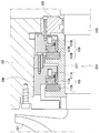
- FIG. 2 shows the details of the dry gas seal 15.
- the dry gas seal 15 includes a rotating ring 16 that rotates integrally with the rotor shaft 11, and stationary rings 19 and 20 that are fixed to the casing 1 a via elastic members 17 and 18 on both sides of the rotating ring 16.
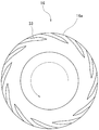
- a spiral groove 33 is formed on the vertical end surface of the rotating ring 16 of the dry gas seal 15, that is, on the surface facing the stationary rings 19 and 20.
- the spiral groove 33 is formed so as to approach the center side from the outer periphery of the rotating ring 16 in the direction opposite to the rotation direction, and the end portion is located between the outer periphery and the inner periphery.
- the spiral groove 33 opens on the outer peripheral surface 16 a of the rotating ring 16.
- the stationary rings 19 and 20 are arranged by elastic members 17 and 18 so as to be in contact with the vertical end surface of the rotating ring 16 substantially perpendicular to the rotor shaft 11.
- a nitrogen supply flow path 24 is connected to the space between the seal member 22 and the seal member 23 so that nitrogen can be supplied from a nitrogen supply source.
- a flow rate adjusting valve 25 is interposed in the nitrogen supply flow path 24 in order to adjust the flow rate of nitrogen passing through the nitrogen supply flow channel 24 to a predetermined value.
- the compressor according to the present invention includes a drain gas flow path 26 and a pressure reference portion 27.
- One end of the drain gas flow channel 26 is connected to communicate with a space 37 between the outer peripheral surface 16a of the rotary ring 16 and the casing 1a via a through hole 35 formed in the casing 1a below the rotary ring 16. The end is connected to the suction flow path 3.
- the drain gas flow path 26 is provided with a check valve 28 and an orifice 29 that allow only the flow from the dry gas seal 15 side toward the suction flow path 3 side.
- the orifice 29 is disposed on the downstream side of the check valve 28.
- the pressure reference portion 27 is provided in the casing 1 a so as to communicate with the space 38 between the casing 1 a on the compression space side of the dry gas seal 15 and the rotor shaft 11. Since the space 38 communicates with the inside of the suction port 2 and the compressor main body 1, the pressure is equalized with the suction pressure. Therefore, the pressure on the compression space side of the casing 1 a can be referred to through the pressure reference portion 27.
- the pressure reference unit 27 is connected to the seal gas regulating valve 8 through a flow path. Therefore, the opening degree of the seal gas regulating valve 8 can be adjusted according to the pressure of the pressure reference portion 27, that is, the pressure on the compression space side of the casing 1a.
- the dry gas seal 15 is compressed by the springs (elastic members) 17 and 18 abutting the stationary rings 19 and 20 against the rotating ring 16 to form a sealing surface. Prevents outflow of gas to be compressed from the machine main body 1 side (compression space side) to the driver (driving machine) 12 side and the atmosphere side.
- the process gas supplied to the dry gas seal 15 via the seal gas flow path 6 passes through a slight gap between the rotary ring 16 and the stationary ring 20 as a seal gas, and then has a lower pressure than the compression space side.
- the air is discharged toward the flare through the discharge channel 21 on the atmosphere side.
- the nitrogen supplied to the space between the seal member 22 and the seal member 23 via the nitrogen supply flow path 24 is a slight gap between the seal member 22 and the rotor shaft 11 or the seal member 23 and the rotor shaft 11. Through the slight gap between. Nitrogen then acts as a sealing gas. Then, the nitrogen that has reached the discharge passage 21 through a slight gap between the seal member 22 and the rotor shaft 11 is discharged toward the flare through the discharge passage 21. Further, nitrogen passing through a slight gap between the seal member 23 and the rotor shaft 11 is discharged to the atmosphere as it is.
- the process gas and liquid are gradually returned to the suction flow path 3 while maintaining the pressures of the seal gas flow path 6 and the drain gas flow path 26. be able to.
- the consumption of process gas is relatively small, and the pressure differential is high (the pressure difference between the supply pressure of the seal gas in the seal gas flow path 6 and the pressure at which the seal gas is discharged is high).
- hunting of the seal gas regulating valve 8 may occur.
- the selection of the seal gas regulating valve 8 can be facilitated by allowing an appropriate amount of process gas and liquid to flow through the orifice 29.
- FIGS. 4 and 5 show a compressor according to a second embodiment of the present invention.
- the compressor according to the second embodiment has almost the same configuration as the compressor according to the first embodiment shown in FIGS. 1 and 2, but an emergency flow path 31 is provided in addition to the configuration of the first embodiment. It has been.
- the emergency flow path 31 has one end connected to the suction flow path 3 and the other end connected to the seal gas flow path 6 downstream from the check valve 9.
- the emergency flow path 31 is provided with a check valve 32 that allows only a flow from the suction flow path 3 side to the seal gas flow path 6 side.
- the seal gas regulating valve 8 is configured to seal the seal gas (a part of the compressed process gas) in the seal gas flow path 6 downstream from the seal gas regulating valve 8 based on the pressure of the pressure reference unit 27.
- the pressure in the seal gas flow path 6 is at least Since the pressure is maintained at the same magnitude as the suction pressure, the “reverse pressure condition”, that is, the state of “supply pressure PS of the seal gas flow path 6 ⁇ suction pressure PI at the suction port 2” can be avoided. Therefore, it is possible to maintain a state in which an appropriate pressure (minimum necessary pressure) is applied to the dry gas seal 15, and it is possible to eliminate the possibility of breakage.
- a rotary ring 39 is provided between the casing 1a at the position where the nitrogen supply flow path 24 is connected and the rotor shaft 11, and a stationary ring 40 is arranged on the atmosphere side with respect to the rotary ring 39.
- a gas seal 15 may be provided.
- a flow rate adjusting valve for adjusting the flow rate may be provided instead of providing the orifice 29 in the drain gas flow path 26, a flow rate adjusting valve for adjusting the flow rate may be provided. According to this configuration, the flow rate of the drain gas passage 26 can be adjusted over a wide range, and the selection of the seal gas adjustment valve 8 can be further facilitated. Even if a gas whose molecular weight or pressure changes is used, the amount of gas returned to the suction side can be maintained at an optimum amount.
- a shutoff valve 42 may be provided in the emergency flow path 31 between the suction flow path 3 and the check valve 32.
- a filter 43 may be interposed in the emergency flow path 31 between the shutoff valve 42 and the check valve 32.
- a seal gas supply source 45 that supplies nitrogen as a seal gas to the seal gas flow path 6 via a check valve 44. May be connected. According to this configuration, the seal gas can be reliably supplied from the seal gas supply source 45 to the seal gas flow path 6. Therefore, the emergency flow path 31 can be omitted. Both the sealing gas supply source 45 and the emergency flow path 31 can be provided. In this case, the seal gas can be reliably supplied from the seal gas channel 6 to the casing 1a.
- the pressure value measured by the pressure reference unit 27 is controlled by a control device (You may make it adjust the opening degree of the seal gas regulating valve 8 indirectly via a control apparatus.
- the space 38 may be equalized with the suction pressure through an external pipe.
- the rotary ring 16 has been described as an example in which the rotation direction is only one direction. However, the rotation ring 16 is not limited to this, and can rotate in both directions where a groove having a sealing function as a dry gas seal is formed on the vertical end surface. A rotating ring may be used.
- the seal gas regulating valve 8 may be any type of regulating valve such as a self-regulating regulating valve or an automatic regulating valve.
- the filter gas, the seal gas adjusting valve 8 and the check valve 9 are provided in the seal gas flow path 6 in the order from the branch point with the discharge flow path 5.
- the present invention is not limited to this, and the order of arrangement of the filter 7, the seal gas adjustment valve 8, and the check valve 9 may be different.
- the orifice 29 may be arranged on the upstream side of the check valve 28.
Landscapes
- Engineering & Computer Science (AREA)
- General Engineering & Computer Science (AREA)
- Mechanical Engineering (AREA)
- Structures Of Non-Positive Displacement Pumps (AREA)
- Mechanical Sealing (AREA)
- Compressor (AREA)
- Sealing Using Fluids, Sealing Without Contact, And Removal Of Oil (AREA)
- Sealing Devices (AREA)
- Applications Or Details Of Rotary Compressors (AREA)
Abstract
Description
1a ケーシング
2 吸込口
3 吸込流路
4 吐出口
5 吐出流路
6 シールガス流路
7 フィルター
8 シールガス調整弁
9 逆止弁
11 ロータ軸
12 ドライバ(駆動機)
13 カップリング
14 駆動軸
15 ドライガスシール
16,39 回転環
17,18 バネ(弾性部材)
19,20,40 静止環
21 排出流路
22,23 シール部材
24 窒素供給流路
25 流量調整弁
26 ドレンガス流路
27 圧力参照部
28 逆止弁
29 オリフィス
31 緊急流路
32 逆止弁
33 溝
35 貫通孔
36 貫通孔
37 空間
38 空間
42 遮断弁
43 フィルター
45 シールガス供給源
Claims (6)
- ロータ軸が略水平になるように配置されたロータを収容する圧縮空間と、該圧縮空間と連通する吸込口および吐出口とが設けられたケーシングを有する圧縮機本体と、
前記圧縮機本体の吸込口に接続された吸込流路と、
前記圧縮機本体の吐出口に接続された吐出流路とを備え、
前記吸込流路から前記吸込口を介して流体を吸い込み、該流体を前記圧縮空間で圧縮して、前記吐出口を介して前記吐出流路に吐出する圧縮機であって、
前記ケーシングと前記ロータ軸の間に配設され、前記ロータ軸に周設された回転環と、前記ロータ軸と略垂直な前記回転環の垂直端面に当接可能となるように弾性部材を介して前記ケーシングに設けられた静止環とを有するドライガスシールと、
前記吐出流路と一端が接続されるとともに前記ドライガスシールの回転環の外周面と前記ケーシングの間の空間と連通するように他端が接続され、シールガス調整弁が介設されたシールガス流路と、
前記回転環の下方の前記ケーシングに形成された貫通孔を介して前記空間と連通するように一端が接続され、他端が前記吸込流路に接続されたドレンガス流路と
を備えることを特徴とする圧縮機。 - 前記ドレンガス流路にオリフィスが介設されたことを特徴とする請求項1に記載の圧縮機。
- 前記ドレンガス流路に流量調整弁が介設されたことを特徴とする請求項1に記載の圧縮機。
- 前記吸込流路と一端が接続され逆止弁を介して前記シールガス流路に他端が接続された緊急流路を備えることを特徴とする請求項1に記載の圧縮機。
- 前記緊急流路に遮断弁を設けたことを特徴とする請求項4に記載の圧縮機。
- 前記シールガス流路にシールガスを供給するシールガス供給源を接続したことを特徴とする請求項1に記載の圧縮機。
Priority Applications (4)
| Application Number | Priority Date | Filing Date | Title |
|---|---|---|---|
| EP11834229.4A EP2631489B1 (en) | 2010-10-22 | 2011-10-11 | Compressor |
| BR112013009472-9A BR112013009472B1 (pt) | 2010-10-22 | 2011-10-11 | compressor |
| CN201180050853.0A CN103168174B (zh) | 2010-10-22 | 2011-10-11 | 压缩机 |
| US13/877,966 US9239061B2 (en) | 2010-10-22 | 2011-10-11 | Compressor employing a dry gas seal |
Applications Claiming Priority (4)
| Application Number | Priority Date | Filing Date | Title |
|---|---|---|---|
| JP2010237547 | 2010-10-22 | ||
| JP2010-237547 | 2010-10-22 | ||
| JP2011159087A JP5231611B2 (ja) | 2010-10-22 | 2011-07-20 | 圧縮機 |
| JP2011-159087 | 2011-07-20 |
Publications (1)
| Publication Number | Publication Date |
|---|---|
| WO2012053389A1 true WO2012053389A1 (ja) | 2012-04-26 |
Family
ID=45975106
Family Applications (1)
| Application Number | Title | Priority Date | Filing Date |
|---|---|---|---|
| PCT/JP2011/073311 Ceased WO2012053389A1 (ja) | 2010-10-22 | 2011-10-11 | 圧縮機 |
Country Status (6)
| Country | Link |
|---|---|
| US (1) | US9239061B2 (ja) |
| EP (1) | EP2631489B1 (ja) |
| JP (1) | JP5231611B2 (ja) |
| CN (1) | CN103168174B (ja) |
| BR (1) | BR112013009472B1 (ja) |
| WO (1) | WO2012053389A1 (ja) |
Cited By (5)
| Publication number | Priority date | Publication date | Assignee | Title |
|---|---|---|---|---|
| CN102644580A (zh) * | 2012-04-28 | 2012-08-22 | 大连华阳光大密封有限公司 | 适用于压缩机的机械密封结构 |
| FR3000167A1 (fr) * | 2012-12-20 | 2014-06-27 | Cryostar Sas | Ensemble joint d'etancheite a gaz pour pompes a liquide cryogenique |
| EP2864643A1 (de) * | 2012-09-06 | 2015-04-29 | Siemens Aktiengesellschaft | Turbomaschine und verfahren zum betrieb |
| WO2017169541A1 (ja) * | 2016-03-28 | 2017-10-05 | 三菱重工コンプレッサ株式会社 | ヒータ一体型フィルタ、及び、回転機械システム |
| JP2025535344A (ja) * | 2022-10-24 | 2025-10-24 | ヌオーヴォ・ピニォーネ・テクノロジー・ソチエタ・レスポンサビリタ・リミタータ | ドライガスシール装置、構成を含むターボ機械、及び方法 |
Families Citing this family (32)
| Publication number | Priority date | Publication date | Assignee | Title |
|---|---|---|---|---|
| JP6079144B2 (ja) * | 2012-11-01 | 2017-02-15 | 株式会社Ihi | 二酸化炭素回収装置 |
| DE102012021637A1 (de) * | 2012-11-02 | 2014-05-08 | Linde Aktiengesellschaft | Verfahren zum Abkühlen einer Kohlenwasserstoff-reichen Fraktion |
| US9624785B2 (en) | 2014-01-24 | 2017-04-18 | Solar Turbines Incorporated | System for monitoring health of a seal |
| JP6601832B2 (ja) * | 2014-11-20 | 2019-11-06 | 三菱重工コンプレッサ株式会社 | シールガス供給制御方法、シールガス供給制御装置、回転機械 |
| DE102014224283A1 (de) * | 2014-11-27 | 2016-06-02 | Robert Bosch Gmbh | Verdichter mit einem Dichtkanal |
| JP6501391B2 (ja) * | 2015-01-23 | 2019-04-17 | 三菱重工コンプレッサ株式会社 | 回転機械システム |
| JP6468859B2 (ja) * | 2015-01-23 | 2019-02-13 | 三菱重工コンプレッサ株式会社 | 回転機械システム |
| CN104564792A (zh) * | 2015-01-26 | 2015-04-29 | 成都成发科能动力工程有限公司 | 轴流压缩机可控式轴端密封结构 |
| AU2016215900B2 (en) * | 2015-02-05 | 2019-03-28 | Eagle Industry Co., Ltd. | Mechanical seal |
| DE102015013659A1 (de) * | 2015-10-22 | 2017-04-27 | Man Diesel & Turbo Se | Trockengasdichtungssystem und Strömungsmaschine mit einem Trockengasdichtungssystem |
| JP6542105B2 (ja) * | 2015-11-12 | 2019-07-10 | イーグル工業株式会社 | 密封装置 |
| CN105782108A (zh) * | 2016-03-24 | 2016-07-20 | 芜湖市中天密封件有限公司 | 一种化工泵水箱式机箱密封件 |
| CN106545523B (zh) * | 2016-10-28 | 2019-05-31 | 沈阳透平机械股份有限公司 | 防止垂直剖分压缩机工作气体泄露的端盖结构及加工方法 |
| WO2018142535A1 (ja) * | 2017-02-02 | 2018-08-09 | 三菱重工コンプレッサ株式会社 | 回転機械 |
| EP3561299B1 (en) | 2017-02-17 | 2021-06-23 | Mitsubishi Heavy Industries Compressor Corporation | Rotary machine |
| GB201708297D0 (en) | 2017-05-24 | 2017-07-05 | Rolls Royce Plc | Preventing electrical breakdown |
| GB201708289D0 (en) | 2017-05-24 | 2017-07-05 | Rolls Royce Plc | Preventing electrical breakdown |
| GB2563021A (en) * | 2017-05-30 | 2018-12-05 | Linde Ag | Refrigeration circuit system and method of maintaining a gas seal of a compressor system |
| US10563663B2 (en) | 2018-04-06 | 2020-02-18 | Solar Turbines Incorporated | Nitrogen purge of compressor dry seal |
| CN113242946B (zh) * | 2018-10-08 | 2022-06-28 | 约翰起重机英国有限公司 | 操作干气密封监测系统的方法 |
| CN109595169B (zh) * | 2019-01-14 | 2019-12-13 | 冰轮环境技术股份有限公司 | 无油螺杆压缩机密封机构及控制方法 |
| JP7551276B2 (ja) * | 2019-01-17 | 2024-09-17 | 株式会社神戸製鋼所 | 圧縮機及びシールガス流量調整方法 |
| DE112021000028B4 (de) | 2020-03-02 | 2025-07-10 | Cap Co., Ltd. | Rezirkulationsgebläse mit einer Spülgas-Einleitungsvorrichtung |
| KR102265200B1 (ko) * | 2020-03-23 | 2021-06-15 | 주식회사 포스코 | 공기분리장치의 액체산소펌프 및 액체산소펌프의 실링가스 공급방법 |
| JP7319636B2 (ja) * | 2020-06-04 | 2023-08-02 | 株式会社大阪送風機製作所 | ブロワ |
| CN114576364B (zh) * | 2020-12-02 | 2025-05-16 | 中国石油化工股份有限公司 | 一种防爆风机氮气轴封装置 |
| JP6994127B1 (ja) * | 2021-03-22 | 2022-01-14 | 株式会社スギノマシン | 減圧乾燥機 |
| IT202200023679A1 (it) * | 2022-11-16 | 2023-02-16 | Nuovo Pignone Tecnologie Srl | Un sistema di compressore in linea multistadio con tenute a gas secco e metodo |
| US12359674B2 (en) | 2023-07-06 | 2025-07-15 | Solar Turbines Incorporated | System and method for injecting dry gases into gas compressor |
| CN117646797B (zh) * | 2024-01-30 | 2024-05-14 | 中密控股股份有限公司 | 一种适用于舰船动力装置冷却剂循环泵用密封 |
| WO2025176972A1 (en) * | 2024-02-21 | 2025-08-28 | Aes Engineering Ltd | Double dry gas seals |
| US20260117771A1 (en) * | 2024-10-31 | 2026-04-30 | Hitachi, Ltd. | Screw Compressor |
Citations (6)
| Publication number | Priority date | Publication date | Assignee | Title |
|---|---|---|---|---|
| JPS6224077U (ja) * | 1985-07-29 | 1987-02-13 | ||
| JPS6338697U (ja) * | 1986-08-28 | 1988-03-12 | ||
| JP2000329238A (ja) * | 1999-05-21 | 2000-11-30 | Nippon Pillar Packing Co Ltd | 非接触形メカニカルシール |
| JP2003097487A (ja) * | 2001-09-25 | 2003-04-03 | Hitachi Ltd | 遠心圧縮機 |
| JP2004308754A (ja) * | 2003-04-04 | 2004-11-04 | Mitsubishi Heavy Ind Ltd | 軸封装置 |
| JP2010121463A (ja) | 2008-11-17 | 2010-06-03 | Kobe Steel Ltd | 増速機内蔵型遠心圧縮機のガスシール構造 |
Family Cites Families (18)
| Publication number | Priority date | Publication date | Assignee | Title |
|---|---|---|---|---|
| JPS6224077A (ja) | 1985-07-24 | 1987-02-02 | Mitsubishi Heavy Ind Ltd | シ−ル液温度保持式軸封装置 |
| JPS6338697A (ja) | 1986-08-04 | 1988-02-19 | Mitsubishi Electric Corp | 回転圧縮機 |
| CH686525A5 (de) * | 1992-07-02 | 1996-04-15 | Escher Wyss Ag | Turbomaschine . |
| US5609342A (en) * | 1993-07-09 | 1997-03-11 | Revolve Technologies, Inc. | Gas shaft seal with flexible converging sealing faces |
| DE69943381D1 (de) * | 1999-07-23 | 2011-06-01 | Hitachi Plant Technologies Ltd | Gleitringdichtung für eine turbomaschine |
| GB0004239D0 (en) * | 2000-02-24 | 2000-04-12 | Crane John Uk Ltd | Seal assemblies |
| US6802689B2 (en) * | 2000-03-09 | 2004-10-12 | Hitachi, Ltd. | Turbo type fluid machine and dry gas seal for use therefor |
| US6655693B2 (en) * | 2001-04-26 | 2003-12-02 | John Crane Inc. | Non-contacting gas compressor seal |
| JP3933469B2 (ja) * | 2001-12-28 | 2007-06-20 | イーグル工業株式会社 | メカニカルシール装置 |
| ITMI20022337A1 (it) * | 2002-11-05 | 2004-05-06 | Nuovo Pignone Spa | Assieme di bilanciamento di spinta assiale per un |
| US20050242515A1 (en) * | 2004-04-28 | 2005-11-03 | Brooks Melvin D | Dry gas seal and method for making the same |
| JP4336286B2 (ja) * | 2004-10-08 | 2009-09-30 | 日本ピラー工業株式会社 | 静圧形ノンコンタクトガスシール |
| JP4734171B2 (ja) * | 2006-05-12 | 2011-07-27 | 株式会社神戸製鋼所 | メカニカルシール |
| EP2213915B1 (en) * | 2007-11-20 | 2018-05-23 | Eagle Industry Co., Ltd. | Mechanical seal and tandem seal |
| CA2747119C (en) * | 2008-12-15 | 2015-09-01 | Flowserve Management Company | Seal leakage gas recovery system |
| US8061984B2 (en) * | 2009-04-06 | 2011-11-22 | Dresser-Rand Company | Dry gas blow down seal |
| CN201433871Y (zh) * | 2009-07-17 | 2010-03-31 | 成都一通密封有限公司 | 高压压缩机干气密封 |
| WO2011122256A1 (ja) * | 2010-03-31 | 2011-10-06 | イーグル工業株式会社 | シール装置用配管接続機構及びメカニカルシール装置 |
-
2011
- 2011-07-20 JP JP2011159087A patent/JP5231611B2/ja active Active
- 2011-10-11 US US13/877,966 patent/US9239061B2/en active Active
- 2011-10-11 CN CN201180050853.0A patent/CN103168174B/zh active Active
- 2011-10-11 WO PCT/JP2011/073311 patent/WO2012053389A1/ja not_active Ceased
- 2011-10-11 EP EP11834229.4A patent/EP2631489B1/en active Active
- 2011-10-11 BR BR112013009472-9A patent/BR112013009472B1/pt active IP Right Grant
Patent Citations (6)
| Publication number | Priority date | Publication date | Assignee | Title |
|---|---|---|---|---|
| JPS6224077U (ja) * | 1985-07-29 | 1987-02-13 | ||
| JPS6338697U (ja) * | 1986-08-28 | 1988-03-12 | ||
| JP2000329238A (ja) * | 1999-05-21 | 2000-11-30 | Nippon Pillar Packing Co Ltd | 非接触形メカニカルシール |
| JP2003097487A (ja) * | 2001-09-25 | 2003-04-03 | Hitachi Ltd | 遠心圧縮機 |
| JP2004308754A (ja) * | 2003-04-04 | 2004-11-04 | Mitsubishi Heavy Ind Ltd | 軸封装置 |
| JP2010121463A (ja) | 2008-11-17 | 2010-06-03 | Kobe Steel Ltd | 増速機内蔵型遠心圧縮機のガスシール構造 |
Cited By (5)
| Publication number | Priority date | Publication date | Assignee | Title |
|---|---|---|---|---|
| CN102644580A (zh) * | 2012-04-28 | 2012-08-22 | 大连华阳光大密封有限公司 | 适用于压缩机的机械密封结构 |
| EP2864643A1 (de) * | 2012-09-06 | 2015-04-29 | Siemens Aktiengesellschaft | Turbomaschine und verfahren zum betrieb |
| FR3000167A1 (fr) * | 2012-12-20 | 2014-06-27 | Cryostar Sas | Ensemble joint d'etancheite a gaz pour pompes a liquide cryogenique |
| WO2017169541A1 (ja) * | 2016-03-28 | 2017-10-05 | 三菱重工コンプレッサ株式会社 | ヒータ一体型フィルタ、及び、回転機械システム |
| JP2025535344A (ja) * | 2022-10-24 | 2025-10-24 | ヌオーヴォ・ピニォーネ・テクノロジー・ソチエタ・レスポンサビリタ・リミタータ | ドライガスシール装置、構成を含むターボ機械、及び方法 |
Also Published As
| Publication number | Publication date |
|---|---|
| BR112013009472A2 (pt) | 2020-06-16 |
| CN103168174B (zh) | 2015-09-30 |
| US9239061B2 (en) | 2016-01-19 |
| CN103168174A (zh) | 2013-06-19 |
| JP5231611B2 (ja) | 2013-07-10 |
| BR112013009472B1 (pt) | 2021-05-18 |
| EP2631489B1 (en) | 2018-09-26 |
| EP2631489A4 (en) | 2017-10-18 |
| JP2012107609A (ja) | 2012-06-07 |
| EP2631489A1 (en) | 2013-08-28 |
| US20130195649A1 (en) | 2013-08-01 |
Similar Documents
| Publication | Publication Date | Title |
|---|---|---|
| JP5231611B2 (ja) | 圧縮機 | |
| US11396883B2 (en) | Reduced emission gas seal | |
| CN1828022B (zh) | 具有单板浮动密封件的涡旋机械 | |
| CN1601106A (zh) | 涡旋机械 | |
| JP5180789B2 (ja) | 増速機内蔵型遠心圧縮機のガスシール構造 | |
| US20190353543A1 (en) | Axial thrust force balancing apparatus for an integrally geared compressor | |
| US11796064B2 (en) | Reduced emission gas seal | |
| JP6810168B2 (ja) | インレットガイドベーン及び圧縮機 | |
| WO2015136803A1 (ja) | オイルフリースクリュ圧縮機 | |
| WO2011135747A1 (ja) | ベーンポンプ | |
| JP5736780B2 (ja) | 遠心圧縮機 | |
| TW201740022A (zh) | 渦卷式泵端部密封 | |
| US10161399B2 (en) | Scroll pump | |
| JP4534142B2 (ja) | 流体圧縮機のスラスト軸受構造 | |
| JPH06174106A (ja) | 無給油式圧縮機の軸封装置 | |
| KR20220100707A (ko) | 슬라이딩 부품 | |
| JP4294212B2 (ja) | 高圧スクリュー圧縮装置 | |
| JP2008215115A (ja) | スクロール圧縮機 | |
| CA3027123C (en) | Reduced emission gas seal | |
| JPH04351318A (ja) | 気体軸受の給気制御方法及び装置 | |
| CN121844154A (zh) | 阀 | |
| JP2006125363A (ja) | スクロール圧縮機 |
Legal Events
| Date | Code | Title | Description |
|---|---|---|---|
| 121 | Ep: the epo has been informed by wipo that ep was designated in this application |
Ref document number: 11834229 Country of ref document: EP Kind code of ref document: A1 |
|
| WWE | Wipo information: entry into national phase |
Ref document number: 13877966 Country of ref document: US |
|
| WWE | Wipo information: entry into national phase |
Ref document number: 2011834229 Country of ref document: EP |
|
| NENP | Non-entry into the national phase |
Ref country code: DE |
|
| REG | Reference to national code |
Ref country code: BR Ref legal event code: B01A Ref document number: 112013009472 Country of ref document: BR |
|
| ENP | Entry into the national phase |
Ref document number: 112013009472 Country of ref document: BR Kind code of ref document: A2 Effective date: 20130418 |