WO2012053621A1 - 着座センサ、及び、それを用いた座席装置 - Google Patents
着座センサ、及び、それを用いた座席装置 Download PDFInfo
- Publication number
- WO2012053621A1 WO2012053621A1 PCT/JP2011/074225 JP2011074225W WO2012053621A1 WO 2012053621 A1 WO2012053621 A1 WO 2012053621A1 JP 2011074225 W JP2011074225 W JP 2011074225W WO 2012053621 A1 WO2012053621 A1 WO 2012053621A1
- Authority
- WO
- WIPO (PCT)
- Prior art keywords
- seating sensor
- cushion pad
- seat
- electrode
- cushion
- Prior art date
- Legal status (The legal status is an assumption and is not a legal conclusion. Google has not performed a legal analysis and makes no representation as to the accuracy of the status listed.)
- Ceased
Links
Images






Classifications
-
- B—PERFORMING OPERATIONS; TRANSPORTING
- B60—VEHICLES IN GENERAL
- B60N—SEATS SPECIALLY ADAPTED FOR VEHICLES; VEHICLE PASSENGER ACCOMMODATION NOT OTHERWISE PROVIDED FOR
- B60N2/00—Seats specially adapted for vehicles; Arrangement or mounting of seats in vehicles
- B60N2/02—Seats specially adapted for vehicles; Arrangement or mounting of seats in vehicles the seat or part thereof being movable, e.g. adjustable
- B60N2/0224—Non-manual adjustments, e.g. with electrical operation
- B60N2/0244—Non-manual adjustments, e.g. with electrical operation with logic circuits
- B60N2/0272—Non-manual adjustments, e.g. with electrical operation with logic circuits using sensors or detectors for detecting the position of seat parts
-
- B—PERFORMING OPERATIONS; TRANSPORTING
- B60—VEHICLES IN GENERAL
- B60N—SEATS SPECIALLY ADAPTED FOR VEHICLES; VEHICLE PASSENGER ACCOMMODATION NOT OTHERWISE PROVIDED FOR
- B60N2/00—Seats specially adapted for vehicles; Arrangement or mounting of seats in vehicles
- B60N2/002—Seats provided with an occupancy detection means mounted therein or thereon
- B60N2/0021—Seats provided with an occupancy detection means mounted therein or thereon characterised by the type of sensor or measurement
- B60N2/003—Seats provided with an occupancy detection means mounted therein or thereon characterised by the type of sensor or measurement characterised by the sensor mounting location in or on the seat
- B60N2/0032—Seats provided with an occupancy detection means mounted therein or thereon characterised by the type of sensor or measurement characterised by the sensor mounting location in or on the seat mounted on springs
-
- B—PERFORMING OPERATIONS; TRANSPORTING
- B60—VEHICLES IN GENERAL
- B60N—SEATS SPECIALLY ADAPTED FOR VEHICLES; VEHICLE PASSENGER ACCOMMODATION NOT OTHERWISE PROVIDED FOR
- B60N2/00—Seats specially adapted for vehicles; Arrangement or mounting of seats in vehicles
- B60N2/002—Seats provided with an occupancy detection means mounted therein or thereon
- B60N2/0021—Seats provided with an occupancy detection means mounted therein or thereon characterised by the type of sensor or measurement
- B60N2/0024—Seats provided with an occupancy detection means mounted therein or thereon characterised by the type of sensor or measurement for identifying, categorising or investigation of the occupant or object on the seat
- B60N2/0026—Seats provided with an occupancy detection means mounted therein or thereon characterised by the type of sensor or measurement for identifying, categorising or investigation of the occupant or object on the seat for distinguishing between humans, animals or objects
-
- B—PERFORMING OPERATIONS; TRANSPORTING
- B60—VEHICLES IN GENERAL
- B60N—SEATS SPECIALLY ADAPTED FOR VEHICLES; VEHICLE PASSENGER ACCOMMODATION NOT OTHERWISE PROVIDED FOR
- B60N2/00—Seats specially adapted for vehicles; Arrangement or mounting of seats in vehicles
- B60N2/002—Seats provided with an occupancy detection means mounted therein or thereon
- B60N2/0021—Seats provided with an occupancy detection means mounted therein or thereon characterised by the type of sensor or measurement
- B60N2/003—Seats provided with an occupancy detection means mounted therein or thereon characterised by the type of sensor or measurement characterised by the sensor mounting location in or on the seat
- B60N2/0031—Seats provided with an occupancy detection means mounted therein or thereon characterised by the type of sensor or measurement characterised by the sensor mounting location in or on the seat mounted on the frame
-
- B—PERFORMING OPERATIONS; TRANSPORTING
- B60—VEHICLES IN GENERAL
- B60N—SEATS SPECIALLY ADAPTED FOR VEHICLES; VEHICLE PASSENGER ACCOMMODATION NOT OTHERWISE PROVIDED FOR
- B60N2/00—Seats specially adapted for vehicles; Arrangement or mounting of seats in vehicles
- B60N2/002—Seats provided with an occupancy detection means mounted therein or thereon
- B60N2/0021—Seats provided with an occupancy detection means mounted therein or thereon characterised by the type of sensor or measurement
- B60N2/003—Seats provided with an occupancy detection means mounted therein or thereon characterised by the type of sensor or measurement characterised by the sensor mounting location in or on the seat
- B60N2/0034—Seats provided with an occupancy detection means mounted therein or thereon characterised by the type of sensor or measurement characterised by the sensor mounting location in or on the seat in, under or on the seat cover
-
- B—PERFORMING OPERATIONS; TRANSPORTING
- B60—VEHICLES IN GENERAL
- B60N—SEATS SPECIALLY ADAPTED FOR VEHICLES; VEHICLE PASSENGER ACCOMMODATION NOT OTHERWISE PROVIDED FOR
- B60N2/00—Seats specially adapted for vehicles; Arrangement or mounting of seats in vehicles
- B60N2/02—Seats specially adapted for vehicles; Arrangement or mounting of seats in vehicles the seat or part thereof being movable, e.g. adjustable
- B60N2/0224—Non-manual adjustments, e.g. with electrical operation
- B60N2/0244—Non-manual adjustments, e.g. with electrical operation with logic circuits
- B60N2/0268—Non-manual adjustments, e.g. with electrical operation with logic circuits using sensors or detectors for adapting the seat or seat part, e.g. to the position of an occupant
-
- B—PERFORMING OPERATIONS; TRANSPORTING
- B60—VEHICLES IN GENERAL
- B60R—VEHICLES, VEHICLE FITTINGS, OR VEHICLE PARTS, NOT OTHERWISE PROVIDED FOR
- B60R21/00—Arrangements or fittings on vehicles for protecting or preventing injuries to occupants or pedestrians in case of accidents or other traffic risks
- B60R21/01—Electrical circuits for triggering passive safety arrangements, e.g. airbags, safety belt tighteners, in case of vehicle accidents or impending vehicle accidents
- B60R21/015—Electrical circuits for triggering passive safety arrangements, e.g. airbags, safety belt tighteners, in case of vehicle accidents or impending vehicle accidents including means for detecting the presence or position of passengers, passenger seats or child seats, and the related safety parameters therefor, e.g. speed or timing of airbag inflation in relation to occupant position or seat belt use
- B60R21/01512—Passenger detection systems
- B60R21/01516—Passenger detection systems using force or pressure sensing means
-
- H—ELECTRICITY
- H01—ELECTRIC ELEMENTS
- H01H—ELECTRIC SWITCHES; RELAYS; SELECTORS; EMERGENCY PROTECTIVE DEVICES
- H01H3/00—Mechanisms for operating contacts
- H01H3/02—Operating parts, i.e. for operating driving mechanism by a mechanical force external to the switch
- H01H3/14—Operating parts, i.e. for operating driving mechanism by a mechanical force external to the switch adapted for operation by a part of the human body other than the hand, e.g. by foot
- H01H3/141—Cushion or mat switches
-
- B—PERFORMING OPERATIONS; TRANSPORTING
- B60—VEHICLES IN GENERAL
- B60N—SEATS SPECIALLY ADAPTED FOR VEHICLES; VEHICLE PASSENGER ACCOMMODATION NOT OTHERWISE PROVIDED FOR
- B60N2210/00—Sensor types, e.g. for passenger detection systems or for controlling seats
- B60N2210/40—Force or pressure sensors
- B60N2210/46—Electric switches
Definitions
- the present invention relates to a seating sensor and a seat device using the seating sensor, and more particularly to a seating sensor capable of appropriately detecting a seating of a person in a state of being placed on a seat pan, and a seating device using the seating sensor.
- a seating sensor capable of appropriately detecting a seating of a person in a state of being placed on a seat pan, and a seating device using the seating sensor.
- an alarm system that detects the wearing of a seat belt when a person gets on and issues a warning when the seat belt is not worn is put into practical use.
- Such an alarm system detects a person's seating and issues a warning if the seat belt is not worn when the person is seated.
- a seating sensor that is disposed inside the seating portion of the seat and detects the seating of the person by a load due to the seating may be used.
- Patent Document 1 describes such a seating sensor.
- the seating sensor described in the following Patent Document 1 has a plurality of on / off type pressure-sensitive switches, and each pressure-sensitive switch has a pair of electrodes facing each other at a predetermined interval. ing.
- the pair of electrodes are provided on the surface of the insulating sheet adhered to both surfaces of the sheet-like spacer, and are opposed to each other through an opening formed in the spacer.
- this seating sensor is disposed between the skin of the seat and the cushion pad, and when a pressure is applied to the pressure sensitive switch by the seating of a person, the insulating sheet bends, so that the pair of electrodes is formed in the opening. Touching, the pressure sensitive switch is turned on.
- FIG. 1 is a diagram showing a distribution of a load that a cushion pad of a seat receives from a person through an epidermis in a state where a person is normally seated on the seat.
- a darker portion indicates a state where the cushion pad receives a higher load.
- the epidermis is interposed between a person and a cushion pad. Accordingly, the human load is transmitted almost directly to the cushion pad, and as shown in FIG. 1, the largest load is applied to the portion where the human buttocks are located on the cushion pad.
- the seating sensor of the said patent document 1 can detect a person's seating by arrange
- an object of the present invention is to provide a seating sensor that can appropriately detect the seating of a person while preventing a sense of incongruity due to the seating sensor, and a seat device using the seating sensor.
- the present inventor has intensively studied a method for preventing the above-mentioned uncomfortable feeling caused by the seating sensor.
- the seating sensor should be disposed under the cushion pad of the seat.
- the cushion pad is interposed between the seated person and the seating sensor, so that it is possible to prevent a sense of incongruity due to the seating sensor during seating.
- the present inventor examined the case where even if a pressing force is received from the cushion pad on the upper side of the seating sensor, no force is received from the lower side of the seating sensor.
- a seating sensor is arranged between a cushion pad and an object that does not deform even when a load is applied, or a case where the lower side of the seating sensor becomes a space.
- the seat pan is generally a strong structure made of metal, so a load due to human seating is applied. Even if pressed, the seat pan does not deform.
- the insulating sheet on the seat pan side does not bend and only the insulating sheet on the cushion pad side is bent even if a pressing force is applied to the seating sensor.
- the pressure sensitive switch is turned on.
- the insulating sheet on the space side does not bend but only the insulating sheet on the cushion pad side is bent and the pressure sensitive switch is turned on.
- a seating sensor of the present invention is a seating sensor disposed below a cushion pad of a seat, and is interposed between a pair of insulating sheets having flexibility and the pair of insulating sheets. And a sheet-like spacer having at least one opening formed thereon, a pair of electrodes provided on the respective surfaces of the pair of insulating sheets and facing each other through the opening, and at least of the pair of insulating sheets A cushion member which is provided on the opposite side to the spacer side on one side and covers at least a part of the opening via the insulating sheet.
- the cushion member when a pressing force is applied, the cushion member is deformed so as to be crushed, and the insulating sheet is pressed by the elastic force. At this time, the cushion member presses the insulating sheet so that the insulating sheet enters the opening of the spacer, and the pair of electrodes are electrically connected to become conductive. Therefore, when the seating sensor is placed on the object with the cushion member sandwiched between the object below the cushion pad and the insulating sheet, even if the object is not deformed by the load, It is possible to bend the insulating sheet when a person is seated.
- the seating sensor may be placed in a state where the cushion member is sandwiched between the cushion pad and the insulating sheet. If arranged in this way, the insulating sheet on the space side does not bend, but the insulating sheet on the cushion pad side is appropriately bent by the cushion member even if the cushion pad is relatively hard. Is possible. In this way, a person's seating can be detected appropriately.
- the cushion member is a member having cushioning properties, and specifically means a member having an elastic force and deforming so as to be crushed when a pressing force is applied.
- the cushion member is made of a resin containing at least one of silicon and polyester.
- the cushion member is made of a resin containing at least one of silicon and polyester having excellent temperature characteristics. A change in load can be suppressed.
- the thickness of the cushion member to be crushed is at least half of the distance between the pair of electrodes.
- the electrode provided on the insulating sheet on the placement member side on which the seating sensor is placed is moved to the other electrode side only by deforming the cushion member without being bent. More than half of the distance between electrodes can be approached. Therefore, it is possible to detect the seating of a person with high sensitivity.
- the said cushion member is provided on the surface on the opposite side to the said spacer side surface in either one of said pair of insulating sheets,
- the 1st cushion member which covers at least one part of the said opening through the said insulating sheet
- a second cushion member that is provided on a surface of the insulating sheet that is not provided with the first cushion member and that is opposite to the surface on the spacer side and covers at least a part of the opening via the insulating sheet. It is preferable to consist of.
- the opening having at least two kinds of sizes is formed in the spacer.
- Each insulating sheet is more difficult to bend as the opening interposed between the insulating sheets is smaller, and a pair of electrodes facing each other through the opening is less likely to be turned on.
- the pressing force received on the lower side of the cushion pad tends not to be uniform. Therefore, if the opening is so small that it is pressed by a large pressing force, it is difficult to turn on at a place where a large pressing force is received, and it is possible to easily turn on at a place where a small pressing force is received.
- depending on the size of the opening it is possible to reduce variations in the ease of turning on the pair of electrodes and the pressing force received on the lower side of the cushion pad. As a result, even when the pressing force received on the lower side of the cushion pad is not uniform, the seating of the person can be adjusted so as to be detected more appropriately.
- the ratio of the cushion member covering the opening is different for each of the different types of openings.
- the seat device of the present invention is characterized by including the above-described seating sensor and a cushion pad.
- the seating sensor when the seating sensor is disposed on the object with the cushion member being sandwiched between the object below the cushion pad and the insulating sheet, the seating sensor is disposed. Even if it is a case where the lower side of the place where it should be is a space, a person's seating can be detected appropriately.
- the mounting member further includes a mounting member provided below the cushion pad, on which the seating sensor is mounted, and the cushioning member is sandwiched between the mounting member and the insulating sheet. It is preferable that the seating sensor is disposed between the cushion pad.
- the seating sensor since the seating sensor is disposed on the mounting member below the cushion pad, it is possible to prevent a sense of incongruity due to the seating sensor.
- the cushion member sandwiched between the mounting member and the insulating sheet presses the insulating sheet on the mounting member side, and the cushion pad presses the other insulating sheet. To do. Therefore, both insulating sheets can be appropriately bent, and the seating of a person can be detected appropriately.
- the cushion member disposed between the mounting member and the insulating sheet adjusts the height of the pressure sensitive switch from the seat pan, there is a gap between the mounting member and the cushion pad. In this case, the load for turning on the pressure sensitive switch can be suppressed from becoming extremely high.
- the placing member may be a seat pan that supports the cushion pad, and the cushion member may be sandwiched between an upper surface of the seat pan and the insulating sheet.
- the mounting member is a pedestal that can be attached to and detached from a part of a plurality of springs stretched over the seat frame, and that mounts the seating sensor above the spring, and the seating surface of the pedestal and the insulating member The cushion member may be sandwiched between seats.
- the mounting member may be a seat frame on which a plurality of springs are stretched, and the cushion member may be sandwiched between the upper surface of the seat frame and the insulating sheet.
- the elastic force of the cushion member is weaker than the elastic force of the cushion pad.
- a seat device it is possible to suppress the vibration from the seat pan from being transmitted to the pressure sensitive switch by the cushion member having a weaker elastic force than the cushion pad, and the switch operates more stably. A person's seating can be detected stably.
- the cushion pad preferably has the same elastic force as the cushion member.
- the seating sensor When a pressure is applied to the seating sensor due to human seating, the seating sensor is pressed with the same pressing force from the mounting member and the cushion pad. Therefore, according to such a seating sensor, the same elastic force is applied to each insulating sheet from the cushion member and the cushion pad, and each insulating sheet can be bent in the same manner. Therefore, it can suppress that the amount of bending of one insulating sheet becomes large, and can improve the detection sensitivity of seating.
- the cushion member and the cushion pad may be made of the same material.
- the elastic force of the cushion member is stronger than the elastic force of the cushion pad.
- the cushion pad contracts more than the cushion member when a person is seated, and the cushion member is prevented from contracting, so that the distance from the mounting member to the pressure sensitive switch is reduced. Can be suppressed. Therefore, heat and vibration transmitted from the mounting member to the pressure-sensitive switch can be absorbed by the cushion member, so that it is possible to suppress fluctuations in the pressing force necessary for turning on the pressure-sensitive switch due to temperature.
- the load for detecting the seating can be prevented from changing depending on the temperature.
- a seating sensor that can appropriately detect the seating of a person while preventing a sense of incongruity by the seating sensor, and a seat device using the seating sensor.
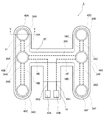
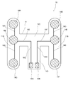
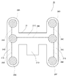
- FIG. 3 is a plan view showing a first electrode sheet shown in FIG. 2. It is a top view which shows the 2nd electrode sheet shown in FIG. It is a top view which shows a spacer.
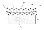
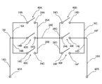
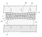
- FIG. 5 is a view showing a state of a cross section taken along line VV in FIG. 2. It is a circuit diagram which shows the circuit structure of the seating sensor shown in FIG. 2 with an equivalent circuit.
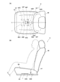
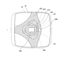
- FIG. 8 It is a figure which shows the mode of the seat apparatus which concerns on 1st Embodiment of this invention. It is a conceptual diagram which shows distribution of the load which a seat pan receives from a person via a skin and a cushion pad in the state which the person seated normally on the seat apparatus. It is a figure which shows a mode that a pressure-sensitive switch turns on in the state by which the seating sensor is arrange
- FIG. 14 It is a top view which shows the seating sensor which concerns on 3rd Embodiment of this invention. It is a top view which shows the 1st electrode sheet of FIG. 14, a 2nd electrode sheet, and a spacer. It is a figure which shows the mode of the seat apparatus which concerns on 3rd Embodiment of this invention. It is a top view which shows the seating sensor which concerns on 4th Embodiment of this invention. It is the upper view and sectional drawing which show a base. It is a figure which shows the mode of the seat apparatus which concerns on 4th Embodiment of this invention. FIG.
- FIG. 20 is a conceptual diagram illustrating a distribution of a load received by a seat frame and a spring via a cushion pad when a person normally sits on the seat device of FIG. 19. It is a figure which shows the mode of a part of seating sensor which concerns on 5th Embodiment of this invention, and a part of seat apparatus. It is a figure which shows the seating sensor which concerns on other embodiment from the same viewpoint as FIG. It is the schematic where it uses for description of the relationship between an electrode and a cushion pad.
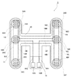
- FIG. 2 is a plan view showing the seating sensor according to the first embodiment of the present invention.
- the seating sensor 1 includes a first electrode sheet 10, a second electrode sheet 20 stacked on the first electrode sheet 10, and a spacer sandwiched between the first electrode sheet 10 and the second electrode sheet 20.
- positioned on the opposite side to the spacer of the 1st electrode sheet 10 is provided as a main component.
- FIG. 3 is a plan view showing the first electrode sheet 10 shown in FIG.
- the first electrode sheet 10 includes a flexible film-like first insulating sheet 11, first electrodes 14A to 14F formed on the surface of the first insulating sheet 11, and first electrodes Terminals 42A and 42B formed on the surface of the insulating sheet 11 are provided as main components.
- the first insulating sheet 11 has the same shape, and a first portion 11A between a pair of parallel first and second portions 11A, 11B and the first portion 11A, the second portion 11B.
- the third portion 11C is a belt-like third portion 11C that extends in a direction perpendicular to the second portion 11B and is connected to the intermediate portions of the first portion 11A and the second portion 11B. It extends in the vertical direction (extends in a direction parallel to the first part 11A and the second part 11B), and one end is connected to the middle part of the third part 11C and the other end is a free end. It is comprised from strip
- a substantially H-shaped shape is formed by the pair of the first portion 11A, the second portion 11B, and the third portion 11C, and the third portion 11C and the fourth portion 11D As a result, a substantially T-shaped shape is formed.
- the first electrodes 14A to 14F have a substantially circular shape.
- the first electrodes 14A to 14F are provided on the pair of the first part 11A and the second part 11B.
- the first electrodes 14A to 14C are provided on the surface of the first portion 11A.
- the first electrodes 14A and 14C are provided at a predetermined interval from the edges of both ends of the first part 11A, and the first electrode 14B is provided at a portion where the third part 11C is connected. Yes.
- the first electrodes 14A to 14C are arranged in a straight line at a distance from each other on the surface of the first portion 11A.
- first electrode 14A and the first electrode 14B are connected to a linear first wiring 16A provided between the first electrode 14A and the first electrode 14B on the surface of the first portion 11A
- the first electrode 14B and the first electrode 14C are connected to a linear first wiring 16B provided between the first electrode 14B and the first electrode 14C on the surface of the first portion 11A.
- the first electrode 14B is connected to the first wiring 16E provided along the longitudinal direction of the third part 11C on the surface of the third part 11C.
- the 1st wiring 16E is connected with the 1st wiring 16G extended along the longitudinal direction of 4th site
- the first electrodes 14D to 14F are provided on the surface of the second portion 11B.
- the first electrodes 14D and 14F are provided at a predetermined interval from the edges of both ends of the second part 11B, and the first electrode 14E is provided at a portion where the third part 11C is connected. Yes.
- the first electrodes 14D to 14F are arranged in a straight line at intervals from each other on the surface of the second portion 11B.
- first electrode 14D and the first electrode 14E are connected to the linear first wiring 16C provided between the first electrode 14D and the first electrode 14E on the surface of the second portion 11B
- the first electrode 14E and the first electrode 14F are connected to a linear first wiring 16D provided between the first electrode 14E and the first electrode 14F on the surface of the second portion 11B.
- the first electrode 14E is connected to the first wiring 16F provided along the longitudinal direction of the third portion 11C on the surface of the third portion 11C.
- the 1st wiring 16F is connected with the 1st wiring 16H extended along the longitudinal direction of 4th site
- the terminals 42A and 42B have a substantially rectangular shape, and the terminals 42A and 42B are arranged in a longitudinal direction of the fourth portion 11D at a position spaced from the edge on the free end side on the surface of the fourth portion 11D. They are juxtaposed along a direction perpendicular to the direction.
- the terminal 42A is connected to the other end of the first wiring 16G whose one end is connected to the first wiring 16E as described above, and the terminal 42B is connected to the first wiring 16F as described above. The other end of the first wiring 16H is connected.
- first electrodes 14A to 14C and the terminal 42A are electrically connected by the first wirings 16A, 16B, 16E, and 16G.
- first electrodes 14D to 14F and the terminal 42B are electrically connected by the first wirings 16C, 16D, 16F, and 16H.
- FIG. 4 is a plan view showing the second electrode sheet shown in FIG.
- the second electrode sheet 20 mainly includes a flexible film-like second insulating sheet 21 and second electrodes 24A to 24F formed on the surface of the second insulating sheet 21. Have as an element.
- the second insulating sheet 21 includes a pair of strip-shaped first portion 21A and second portion 21B having the same shape and size as the first portion 11A and the second portion 11B in the first insulating sheet 11, and the first insulation.
- the first part 21C having the same shape and size as the third part 11C in the sheet 11 and the fourth part 21D having the same width and the same length as the fourth part 11D of the first insulating sheet 11 It consists of.
- the first part 21A, the second part 21B, and the third part 21C are the first part 11A and the first part in the first insulating sheet 11 when the first electrode sheet 10 and the second electrode sheet 20 are overlapped.
- the two parts 11B and the third part 11C are respectively connected so as to completely overlap.
- the fourth portion 21D of the second insulating sheet 21 overlaps the fourth portion 11D of the first electrode sheet when the first electrode sheet 10 and the second electrode sheet 20 are overlapped, and the first electrode sheet 10
- the terminals 42A and 42B are connected to the third portion 21C so as to be exposed.
- the second insulating sheet 21 and the first insulating sheet 11 have the same flexibility and are configured to be bent in the same manner when the same force is applied.
- the second electrodes 24A to 24F have the same shape and size as the first electrodes 14A to 14F. Further, the second electrodes 24A to 24F are formed on the surface of the second insulating sheet 21 on the first electrode sheet 10 side when the second electrode sheet 20 is overlaid on the first electrode sheet 10. 14F is provided at a position completely overlapping with 14F.
- the second electrode 24A and the second electrode 24B are connected to a linear second wiring 26A provided between the second electrode 24A and the second electrode 24B on the surface of the first portion 21A
- the two electrodes 24B and the second electrode 24C are connected to a linear second wiring 26B provided between the second electrode 24B and the second electrode 24C on the surface of the first portion 21A
- the second electrode 24D and the second electrode 24E are connected to a linear second wiring 26C provided between the second electrode 24D and the second electrode 24E on the surface of the second portion 21B
- the two electrodes 24E and the second electrode 24F are connected to a linear second wiring 26D provided between the second electrode 24E and the second electrode 24F on the surface of the second portion 21B.
- the second electrode 24B and the second electrode 24E are connected to the second wiring 26E provided on the surface of the third portion 21C along the longitudinal direction of the third portion 21C of the second insulating sheet 21, respectively.
- the second electrodes 24A to 24F are electrically connected by the second wirings 26A to 26E.
- FIG. 5 is a plan view showing a spacer sandwiched between the first electrode sheet 10 and the second electrode sheet 20.
- the spacer 30 is composed of a flexible insulating sheet 31. As shown in FIG. 5, the spacer 30 has the same outer shape as the second electrode sheet 20.
- openings 34A to 34F having the same size are formed in the spacer 30.
- the openings 34A to 34F have a substantially circular periphery and are slightly smaller in diameter than the first electrodes 14A to 14F.
- the openings 34A to 34F are formed in the outer peripheries of the first electrodes 14A to 14F, respectively, when the spacer 30 is overlapped with the first electrode sheet 10 and the spacer 30 is viewed along the direction perpendicular to the spacer 30.
- the openings 34A to 34F are formed at positions where they can be accommodated.
- the spacer 30 is formed with slits 36A to 36E which are air slits and spatially connect the openings 34A to 34F.
- the opening 34A and the opening 34B are connected to the slit 36A
- the opening 34B and the opening 34C are connected to the slit 36B
- the opening 34D and the opening 34E are connected to the slit 36C
- the opening 34E and the opening 34F are connected to the slit 36D
- the opening 34B and the opening 34E are connected to the slit 36E.
- the spacer 30 is formed with a gas outlet 35 and a slit 36F connecting the gas outlet 35 and the slit 36E. Accordingly, the openings 34A to 34F are spatially connected to the outside of the spacer 30 through the gas outlet 35 and the slits 36A to 36F.
- an adhesive (not shown) for adhering to the first electrode sheet 10 and the second electrode sheet 20 is applied to both surfaces of the spacer 30.
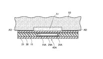
- FIG. 6 is a view showing a state of a cross section taken along line VV shown in FIG.
- the seating sensor 1 has the first electrode sheet 10 and the second electrode sheet 20 overlapped with the spacer 30 interposed therebetween as described above, and is applied to both surfaces of the spacer 30. Are fixed and integrated with each other by the adhesive.
- the first electrode of the first electrode sheet 10 is viewed from a direction perpendicular to the seating sensor 1.
- 14A and the second electrode 24A of the second electrode sheet 20 are completely overlapped, and the opening 34A formed in the spacer 30 is within the outer periphery of the first electrode 14A and the second electrode 24A.
- the first electrode 14A and the second electrode 24A are opposed to each other at a predetermined interval by a spacer 30 as shown in FIG.
- the pressure-sensitive switch 40A having the first and second insulating sheets 11 and 21, the spacer 30 in which the opening 34A is formed, and the pair of electrodes 14A and 24A facing each other through the opening 34A is configured. Is done.
- the other first electrodes 14B to 14F and the other second electrodes 24B to 24F face each other at predetermined intervals in the openings 34B to 34F of the spacer 30, respectively. As shown in FIG. 40B to 40F are configured.
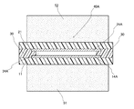
- a cushion member 51 having an elastic force and deforming so as to be crushed when a pressing force is applied is provided on the side of the first insulating sheet 11 opposite to the spacer 30 side.
- the cushion member 51 is made of a sponge-like resin provided with a large number of holes, a nonwoven fabric intertwined with resin fibers having elasticity, rubber, or the like.
- the cushion member 51 is shaped to fit within the outer periphery of the second insulating sheet 21 as shown in FIG.
- the cushion member 51 is disposed so as to cover at least the openings 34A to 34F of the spacer 30 via the first insulating sheet 11 when viewed from a direction perpendicular to the spacer 30.
- the thickness at which the cushion member 51 is crushed is at least half the distance between the opposing electrodes in each of the pressure sensitive switches 40A to 40F.
- FIG. 7 is a circuit diagram showing an equivalent circuit of the circuit configuration of the seating sensor shown in FIG.
- the pressure sensitive switches 40A to 40F configured as described above are provided on the surface of the first wirings 16A to 16D formed on the surface of the first insulating sheet 11 and the surface of the second insulating sheet 21, as shown in FIG.
- the second wires 26A to 26E are connected to each other.
- the circuit of the seating sensor 1 is configured by connecting the pressure sensitive switches 40A to 40F.
- An OR circuit is configured in the pressure-sensitive switch group including the pressure-sensitive switch 40A, the pressure-sensitive switch 40B, and the pressure-sensitive switch 40C, and the pressure-sensitive switch including the pressure-sensitive switch 40D, the pressure-sensitive switch 40E, and the pressure-sensitive switch 40F.
- An OR circuit is configured in the group.
- the AND circuit includes a pressure sensitive switch group including the pressure sensitive switch 40A, the pressure sensitive switch 40B, and the pressure sensitive switch 40C, and a pressure sensitive switch group including the pressure sensitive switch 40D, the pressure sensitive switch 40E, and the pressure sensitive switch 40F. Composed.
- the pressure-sensitive switches 40A to 40F constitute an AND-OR circuit.
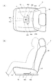
- FIG. 8 is a diagram illustrating a state of the seat device according to the present embodiment.
- FIG. 8A is a diagram showing a state of the seat device 9 in which the seating sensor 1 is disposed from above
- FIG. 8B is a seat device in which the seating sensor 1 is disposed. It is a figure which shows the mode of 9 from the side.
- the seat device 9 is disposed on the seat pan 92, the cushion pad 93 disposed on the seat pan 92, the backrest 96, and the seat pan 92.
- the seating sensor 1 is sandwiched between the seat pan 92 and the cushion pad 93.
- the seat pan 92 is a support member that is disposed below the cushion pad 93 and supports the cushion pad 93.
- the seat pan 92 is a mounting member on which the seating sensor is mounted.
- the seat pan 92 of the present embodiment is formed by bending a highly rigid metal plate, and as shown in FIG. 8A, the center is parallel to the front and rear direction of the cushion pad 93 and passes through the center in the width direction.
- a line (a line on a vertical plane passing through the center of the cushion pad 93 in the width direction) L is symmetric.
- the seat pan 92 is formed with a substantially square hole 94A substantially in the center, and this hole 94A is formed in front of the hip point HP when a person is normally seated on the seat device 9, A hole 94B is formed behind the hip point HP.
- “regular seating” means sitting with the buttocks positioned deep in the seating surface and the back in contact with the backrest 96
- “hip point” refers to FIG. As shown in (B), it is the point where the buttock is at the lowest position when a person is seated.
- the cushion pad 93 is made of urethane foam and has a cushioning property. That is, the cushion pad 93 has an elastic force and is deformed so as to be crushed when a pressing force is applied.
- the cushion pad 93 is covered with a cloth skin (not shown).
- the backrest 96 is connected to the seat pan 92 by means (not shown) so as to come into contact with the cushion pad 93 behind the cushion pad 93.
- the seating sensor 1 is arranged below the cushion pad 93 so as to receive a pressing force from the cushion pad 93.
- the seating sensor 1 is disposed on the seat pan 92 in the seat device 9 such as a vehicle, and is sandwiched between the seat pan 92 and the cushion pad 93.
- the second insulating sheet 21 is arranged on the cushion pad 93 side and is in contact with the cushion pad 93, and further, the first insulating sheet 11 is arranged on the seat pan side.
- the cushion member 51 is sandwiched between the seat pan 92 and the first insulating sheet 11.
- a pressure sensitive switch 40C is disposed in a region adjacent to the left side with respect to the hole 94A of the seat pan 92, and the pressure sensitive switch 40B is disposed in front of the pressure sensitive switch 40C.
- the pressure-sensitive switch 40A is disposed, and the pressure-sensitive switch 40F is disposed in a region adjacent to the right side with respect to the hole 94A of the seat pan 92.
- the pressure-sensitive switch 40E and the pressure-sensitive switch 40F are disposed in front of the pressure-sensitive switch 40F.
- a switch 40D is arranged.
- the seating sensor 1 is arranged such that the pressure sensitive switches 40A to 40C are located on the left side with respect to the center line L passing through the center of the cushion pad 93, and the pressure sensitive switches 40D to 40F are located on the right side.
- a line connecting the pressure sensitive switch 40A and the pressure sensitive switch 40D is perpendicular to the center line L, and the pressure sensitive switch 40A and the pressure sensitive switch 40D are in a position symmetrical with respect to the center line L. Be placed.
- the line connecting the pressure-sensitive switch 40B and the pressure-sensitive switch 40E is perpendicular to the center line L, and the pressure-sensitive switch 40B and the pressure-sensitive switch 40E are symmetrical with respect to the center line L. Placed in.
- the line connecting the pressure sensitive switch 40C and the pressure sensitive switch 40F is perpendicular to the center line L, and the pressure sensitive switch 40C and the pressure sensitive switch 40F are in positions symmetrical with each other with respect to the center line L. Be placed. Since the AND circuit is configured by the pressure sensitive switches 40A to 40C and the pressure sensitive switches 40D to 40F as described above, the pressure sensitive switch group disposed on the left side of the center line L and the center line L An AND circuit is configured by the pressure-sensitive switch group arranged on the right side. Further, as described above, the OR circuit is configured in the pressure-sensitive switch group including the pressure-sensitive switches 40A to 40C, and the OR circuit is configured in the pressure-sensitive switch group including the pressure-sensitive switches 40D to 40F. Each of the plurality of pressure sensitive switches arranged on the left side of L and the plurality of pressure sensitive switches arranged on the right side of the center line L constitutes an OR circuit.
- the terminals 42A and 42B are led out from the holes 94A and are electrically connected to an external power source and a measurement unit (not shown), and a voltage is applied to the terminals 42A and 42B.
- the cushion pad 93 has the same elastic force as that of the cushion member 51. Therefore, when the same pressing force is applied to the cushion pad 93 and the cushion member 51, the cushion pad 93 and the cushion member 51 press the first insulating sheet 11 and the second insulating sheet 21 in the same manner.
- FIG. 9 is a concept similar to FIG. 1 showing the distribution of a load received from a person through the epidermis and cushion pad 93 by the seat pan 92 of the seat apparatus 9 in a state where the person is normally seated on the seat apparatus 9.
- FIG. 9 the region 92A adjacent to the hole 94A formed in the seat pan 92 receives the highest pressing force from the cushion pad 93, and the region 92B outside the region 92A has the next highest pressing force.
- the region 92C outside the region 92B is subjected to the next highest pressing force.
- the pressing force is concentrated on the place where the person's buttocks are located, but as shown in FIG. 9,
- the pressing force that the seat pan 92 receives from the cushion pad 93 due to a human load is widely dispersed on the seat pan 92.
- the seat pan 92 is stronger than the other regions in the region adjacent to the hole 94 ⁇ / b> A formed on the center line L in front of the hip point HP. Pressed with force.
- the vicinity of the center of the cushion pad 93 in the width direction that is, the vicinity of the center line L tends to be pressed with a large force.
- the area adjacent to the hole 94A formed at the center in the width direction of the cushion pad 93 is pressed with a greater force than the area adjacent to the other hole in front of the hip point HP.
- the place (maximum load area) MG where the seat pan 92 receives a particularly large pressing force from the cushion pad 93 is an area adjacent to the hole 94A in the lateral direction in the area 92A.
- the person when a person is seated as described above, the person normally sits symmetrically at the approximate center in the width direction of the cushion pad, so that the pressing force that the seat pan 92 receives from the cushion pad 93 is applied to the center line L. It is almost symmetrical. Further, when a person sits normally on the seat device 9, the person's pelvis is arranged symmetrically in the left-right direction with respect to the center line L. For this reason, the distribution of the pressing force that the seat pan 92 receives from the cushion pad also extends in the lateral direction. Thus, the distribution of the pressing force spreads in the front direction and the width direction of the seat pan 92.
- the place (maximum load area) MG where the seat pan 92 receives a particularly large pressing force from the cushion pad 93 is an area laterally adjacent to the hole 94A in the area 92A.
- the pressing force received by the seat pan 92 from the cushion pad 93 is approximately symmetrical with respect to the center line L.
- the person's pelvis is arranged symmetrically in the left-right direction with respect to the center line L. For this reason, the distribution of the pressing force that the seat pan 92 receives from the cushion pad also extends in the lateral direction.
- the maximum load region is a place where the seat pan receives the greatest pressing force from the cushion pad, with the pressing force at the location where the seat pan receives the least pressing force from the cushion pad being zero.
- the pressing force is 100, it refers to a region that receives 90 or more pressing force.
- the pressure sensitive switches 40C and 40F are arranged in the regions adjacent to the sides of the holes 94A of the seat pan 92, and the pressure sensitive switches 40B and 40E are arranged in front of the pressure sensitive switches 40C and 40F. Further, pressure sensitive switches 40A and 40D are arranged in front. In the present embodiment, at least a place where the pressure sensitive switches 40C and 40F and the pressure sensitive switches 40B and 40E are arranged overlaps the maximum load region MG. Therefore, each pressure-sensitive switch 40C, 40F, 40B, 40E can appropriately detect the pressing force caused by the seating of the person when the person is seated normally.
- the pressure-sensitive switches 40A and 40D are also arranged at a place where a relatively large pressing force is received when a person is seated normally, and when the person is seated normally, the pressing force due to the seating of the person is properly detected. can do.
- the pressure-sensitive switches 40 ⁇ / b> A and 40 ⁇ / b> D can appropriately detect the pressing force caused by the person sitting even when the person sits in front of the seat device 9.
- FIG. 10 is a view showing, from the same viewpoint as FIG. 6, that the pressure-sensitive switch is turned on in the state where the seating sensor is arranged in the seat as shown in FIG.
- FIG. 10 only a part of the seat pan 92 and the cushion pad 93 is shown for easy understanding.
- the first insulating sheet 11 receives the pressing force from the cushion member 51 by the elastic force of the cushion member 51 and bends so as to enter the opening 34 ⁇ / b> A of the spacer 30.
- the second insulating sheet 21 receives the pressing force from the cushion pad 93 as described above and bends so as to enter the opening 34 ⁇ / b> A of the spacer 30. Therefore, the first electrode 14 ⁇ / b> A provided on the first insulating sheet 11 and the second electrode 24 ⁇ / b> A provided on the second insulating sheet 21 are in contact with each other through the opening 34 ⁇ / b> A of the spacer 30. Thus, the pressure sensitive switch 40A is turned on.
- the cushion member 51 is crushed so that the thickness of the cushion member 51 is half or more of the distance between the first electrode 14A and the second electrode 24A.
- the first electrode 14A provided on the insulating sheet 11 can be brought closer to the second electrode 24A side by more than half the distance between the electrodes only by deforming the 51 without being bent, and the pressure sensitive switch 40A is turned on. Made easy.
- the cushion pad 93 has the same elastic force as that of the cushion member 51. Therefore, the cushion member 51 and the cushion pad 93 are the first insulating sheet 11 and the second insulating sheet, respectively.
- the sheet 21 is pressed with the same elastic force. Therefore, the insulating sheets 11 and 21 are bent in the same manner, and the pair of electrodes 14A and 24A are in contact with each other in the vicinity of the substantially center in the thickness direction of the spacer 30 in the opening 34A. For this reason, in the seat apparatus of this embodiment, it can suppress that the deflection amount of one insulating sheet of the seating sensor 1 becomes large, and can improve the detection sensitivity of seating.
- the air in the opening 34A is discharged from the gas outlet 35 through the slits 36A, 36E, and 36F shown in FIG. Therefore, when a pressing force is applied to the seating sensor 1, the first insulating sheet 11 and the second insulating sheet 21 can be appropriately bent.
- the other pressure sensitive switches 40B to 40F are flexed by the first insulating sheet 11 and the second insulating sheet 21 being pressed by the elastic force of the cushion member 51 and the cushion pad 93 in the same manner as the pressure sensitive switch 40A. Turn on. At this time, air in the openings 34B to 34F is discharged from the gas outlet 35 through the slits 36B to 36E. Accordingly, similarly to when the pressure sensitive switch 40A is turned on, the first insulating sheet 11 and the second insulating sheet can be appropriately bent, and the pair of electrodes of the pressure sensitive switches 40B to 40F can be easily brought into contact with each other. .
- the AND-OR circuit is configured by the pressure sensitive switches 40A to 40F as described above, at least one of the pressure sensitive switch 40A, the pressure sensitive switch 40B, and the pressure sensitive switch 40C, the pressure sensitive switch 40D, and the pressure sensitive switch are provided.
- the switch 40E and the pressure sensitive switch 40F is turned on, the terminal 42A and the terminal 42B are conducted.
- the seating of the person is detected by measuring a sensing signal sensed by the seating sensor 1 by a measurement unit (not shown).
- the seating sensor 1 in the present embodiment when a pressing force is applied to the seating sensor 1 due to the seating of a person, the cushion member 51 is deformed so as to be crushed, and the insulating sheet is caused by its elastic force. 11 is pressed. At this time, the cushion member 51 presses the insulating sheet 11 so that the insulating sheet 11 enters the openings 34A to 34F of the spacer 30. Accordingly, the seating sensor 1 is arranged such that the cushion member 51 is sandwiched between the seat pan 92 and the insulating sheet 11 as in the seat device 9, so that the seat pan 92 side is insulated when a person is seated. The sheet 11 can be appropriately bent.
- the seating sensor 1 of the present invention it is possible to appropriately detect the seating of a person in a state of being placed on the seat pan 92.
- the seating sensor 1 is disposed between the seat pan 92 and the cushion pad 93, so that the person who is seated differs from the feel of the cushion pad 93 by the seating sensor 1.
- the seat device 9 using the seating sensor 1 can appropriately detect the seating of a person.
- the cushion member 51 disposed between the seat pan 92 and the first insulating sheet 11 adjusts the height of the pressure sensitive switches 40A to 40F from the seat pan 92. Even when there is a gap between them, it is possible to suppress the load for turning on the pressure sensitive switches 40A to 40F from becoming extremely high.
- the pressure sensitive switches 40A to 40C and the pressure sensitive switches 40D to F are disposed on the left side and the right side with respect to the center line L passing through the center of the cushion pad 93 in the width direction. It is possible to appropriately detect the seating of a person and suppress erroneous detection of a load.
- the person sitting in the seat usually sits facing the front of the seat.
- the left and right pelvises of the person's buttocks are aligned in a direction perpendicular to the front-rear direction of the cushion pad 93 and press the cushion pad 93. Therefore, according to the seat device 9, the pressure-sensitive switch 40A, the pressure-sensitive switch 40D, the pressure-sensitive switch 40B, the pressure-sensitive switch 40E, and the pressure-sensitive switch are arranged on the left and right sides with respect to the center line L.
- 40C and the pressure-sensitive switch 40F are arranged in a direction perpendicular to the front-rear direction of the cushion pad 93, so that the seating of a person can be detected more appropriately.
- the left and right pelvises of the person's buttocks are parallel to the front-rear direction of the cushion pad 93.
- the cushion pads are pressed side by side at symmetrical positions. Therefore, according to the seat device 9, the pressure-sensitive switch 40A and the pressure-sensitive switch 40D, the pressure-sensitive switch 40B and the pressure-sensitive switch 40E, and the pressure-sensitive switch 40C and the pressure-sensitive switch 40F are located with respect to the center line L. Therefore, human seating can be detected more appropriately.
- the insulating sheet 11 of the first electrode sheet 10, the insulating sheet 21 of the second electrode sheet 20, and the spacer 30 are made of a flexible insulating resin.
- a resin include polyethylene terephthalate (PET), polyethylene naphthalate (PEN), and polyimide (PI).
- PET polyethylene terephthalate
- PEN polyethylene naphthalate
- PI polyimide
- PEN is preferable from the viewpoint of excellent heat resistance.
- the adhesive applied to both surfaces of the spacer 30 is preferably an acrylic adhesive, for example, an acrylic polymer using one or more (meth) acrylic acid alkyl esters as monomer components.
- the first electrodes 14A to 14F, the second electrodes 24A to 24F, the first wirings 16A to 16H, the second wirings 26A to 26E, and the terminals 42A and 42B are made of conductive paste or plating. It is comprised from the metal foil etc. which are formed by. Among these, a part may be comprised with an electroconductive paste, and another part may be comprised with the metal foil by plating. Examples of the conductive paste include various metal pastes such as silver paste, carbon paste, and the like. Moreover, as metal foil formed by plating, copper, nickel, or these laminated bodies are mentioned.
- the cushion member 51 is a member having an elastic force as described above and deforming so as to be crushed. Although it will not be restrict
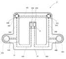
- FIG. 11 is a plan view showing a seating sensor used in the seat device according to the second embodiment of the present invention.
- the seating sensor 2 in the present embodiment is different from the seating sensor 1 of the first embodiment in that the first electrodes 14A to 14F of the pressure sensitive switches 40A to 40F are composed of comb electrodes. .
- FIG. 12 is a plan view showing the first electrode sheet shown in FIG.
- the comb electrodes constituting the first electrodes 14A to 14F a plurality of conductors parallel to each other are connected to each other on one side, and another plurality of conductors parallel to each other are further connected. Connected to each other on the other side. And it arrange
- the comb electrode has a pair of parallel conductors insulated from each other in one electrode.
- a plurality of parallel conductors connected on one side of the first electrode 14A are connected to one end of the first wiring 16A extending from the first electrode 14A to the first electrode 14B along the longitudinal direction of the first portion 11A. Connected. Furthermore, the other plurality of parallel conductors connected on the other side of the first electrode 14A are connected to the first wiring 16I extending from the first electrode 14A to the first electrode 14B along the longitudinal direction of the first portion 11A. Connected to one end. The plurality of parallel conductors connected on one side of the first electrode 14B are one end of the first wiring 16B extending from the first electrode 14B to the first electrode 14C along the longitudinal direction of the first portion 11A, And it is connected to the other end of the first wiring 16A.
- the other plurality of parallel conductors connected on the other side of the first electrode 14B are connected to the first wiring 16J extending from the first electrode 14B to the first electrode 14C along the longitudinal direction of the first portion 11A.
- One end is connected to the other end of the first wiring 16I.
- the plurality of parallel conductors connected on one side of the first electrode 14C are connected to the other end of the first wiring 16B, and further, the other plurality of parallel conductors connected on the other side of the first electrode 14C.
- the conductor is connected to the other end of the first wiring 16J.
- the plurality of parallel conductors connected on one side of the first electrode 14D are connected to one end of the first wiring 16C extending from the first electrode 14D to the first electrode 14E along the longitudinal direction of the second portion 11B. Connected. Furthermore, the other plurality of parallel conductors connected on the other side of the first electrode 14D are connected to the first wiring 16K extending from the first electrode 14D to the first electrode 14E along the longitudinal direction of the second portion 11B. Connected to one end.
- the plurality of parallel conductors connected on one side of the first electrode 14E are one end of the first wiring 16D extending from the first electrode 14E to the first electrode 14F along the longitudinal direction of the second portion 11B, And it is connected to the other end of the first wiring 16C.
- the other plurality of parallel conductors connected on the other side of the first electrode 14B are connected to the first wiring 16L extending from the first electrode 14E to the first electrode 14F along the longitudinal direction of the second portion 11B. One end is connected to the other end of the first wiring 16K.
- the plurality of parallel conductors connected on one side of the first electrode 14F are connected to the other end of the first wiring 16D, and further, the other plurality of parallel conductors connected on the other side of the first electrode 14F.
- the conductor is connected to the other end of the first wiring 16L.
- the plurality of parallel conductors connected on one side of the first electrode 14B are connected to the first wiring 16E similar to that of the first embodiment, and the plurality of parallel conductors connected on one side of the first electrode 14E. These parallel conductors are connected to the first wiring 16F similar to the first embodiment. Further, the plurality of parallel conductors connected on the other side of the first electrode 14A are connected to one end of the first wiring 16M. As shown in FIG. 12, the first wiring 16M bypasses a plurality of parallel conductors connected on one side of the first electrode 14A, and extends in the longitudinal direction of the first portion 11A. In a portion where the portion 11A and the third portion 11C are connected, the portion is bent vertically and extends along the longitudinal direction of the third portion 11C.
- the first wiring 16M bends again vertically at the portion where the third part 11C and the second part 11B are connected, and extends along the longitudinal direction of the second part 11B toward the first electrode 14D. .
- the first wiring 16K bypasses the plurality of parallel conductors connected on one side of the first electrode 14D, and the other end is connected to the plurality of parallel conductors connected on the other side of the first electrode 14D. Is done.
- FIG. 13 is a plan view showing the second electrode sheet shown in FIG. As shown in FIG. 13, the second electrode sheet 20 of the present embodiment is different from the second electrode sheet 20 of the first embodiment in that the second wirings 26A to 26E are not provided.
- the 1st electrode sheet 10 and the 2nd electrode sheet 20 which are shown in FIG. 12 are piled up and integrated via the spacer 30 similar to 1st Embodiment.
- an OR circuit is configured in the pressure-sensitive switch group including the pressure-sensitive switches 40A to 40C, and an OR circuit is configured in the pressure-sensitive switch group including the pressure-sensitive switches 40D to 40F.
- an AND circuit is configured by the pressure sensitive switch group including the pressure sensitive switches 40A to 40C and the pressure sensitive switch group including the pressure sensitive switches 40D to 40F, and the AND-OR circuit is configured by the pressure sensitive switches 40A to 40F. Is configured.
- the seating sensor 2 is arranged in the seat device in the same manner as the seating sensor 1 according to the first embodiment.
- pressure is applied by the pressing force from the cushion pad 93 and the seat pan 92.
- the switches 40A to 40F are pressed.
- at least one of the second electrodes 24A to 24C comes into contact with the parallel conductors in the first electrodes 14A to 14C. Therefore, a pair of parallel conductors insulated from each other in at least one of the first electrodes 14A to 14C are electrically connected via the second electrodes 24A to 24C.
- at least one of the second electrodes 24D to 24F is in contact with the parallel conductors in the first electrodes 14D to 14F.
- a pair of parallel conductors insulated from each other in at least one of the first electrodes 14D to 14F are electrically connected via the second electrodes 24D to 24F.
- at least one of the pressure sensitive switches 40A to 40C and at least one of the pressure sensitive switches 40D to 40F are turned on.
- the seating sensor 2 detects the seating of the person.
- FIG. 14 is a plan view showing a seating sensor according to a third embodiment of the present invention.
- the seating sensor 3 in the present embodiment is different from the seating sensor 1 in the first embodiment in terms of the sensor shape, the number of pressure sensitive switches, and the size of the pressure sensitive switch.
- the shape of the seating sensor 1 in the first embodiment is substantially H-shaped, whereas the shape of the seating sensor 3 in the present embodiment is substantially rectangular with an opening.
- six pressure sensitive switches 40A to 40F are applied, whereas in the present embodiment, four pressure sensitive switches 40A to 40D are applied.
- the size of each of the pressure sensitive switches 40A to 40F is the same, whereas in this embodiment, the sizes of the pressure sensitive switches 40A and 40D are different from those of 40B and 40C. The size of is applied.
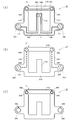
- FIG. 15 is a plan view showing the first electrode sheet, the second electrode sheet, and the spacer of FIG. Specifically, FIG. 15A shows the first electrode sheet of FIG. 14, FIG. 15B shows the second electrode sheet of FIG. 14, and FIG. 15C shows the spacer.
- the first electrode sheet 10 includes a first insulating sheet 11 and first electrodes 14A to 14D provided on the surface of the first insulating sheet 11 as main components.
- the first insulating sheet 11 is composed of strip-shaped first part 11A to seventh part 11G.
- the first part 11A to the fourth part 11D are connected and formed in a substantially quadrangular shape having a substantially quadrangular opening.
- the fifth part 11E extends from the middle part of the second part 11B to the outside of the opening, and the sixth part 11F extends from the middle part of the third part 11C to the outside of the opening, and the fifth part 11E and Each end of 11F is an open end.
- the seventh portion 11G extends from the middle portion of the first portion 11A in the longitudinal direction to the inside of the opening, and its end is an open end.
- the first insulating sheet 11 is bilaterally symmetric with respect to a line passing through the center of the seventh portion 11G and extending along the longitudinal direction of the seventh portion 11G (hereinafter referred to as tail centerline).
- the first electrodes 14A to 14D are substantially circular, but the diameters of the first electrodes 14A and 14D are different from the diameters of the first electrodes 14B and 14C. In the present embodiment, the first electrodes 14A and 14D have a larger diameter than the first electrodes 14B and 14C.
- the first electrode 14A is provided on the fifth part 11E, and the first electrode 14D is provided on the sixth part 11F.
- the first electrode 14A and the first electrode 14D are symmetric with respect to the tail center line.
- the first electrode 14B is provided on the connecting portion between the second portion 11B and the fourth portion 11D
- the first electrode 14C is provided on the connecting portion between the third portion 11C and the fourth portion 11D.
- the electrode 14B and the first electrode 14C are symmetric with respect to the tail center line.
- a terminal 42A provided on the seventh part 11G is electrically connected to the first electrode 14A by a first wiring 16A, and a terminal 42B provided on the seventh part 11G is connected to the first electrode 14D by the first wiring. 16B is electrically connected. The first electrodes 14B and 14C are electrically connected by the first wiring 16C.
- the second electrode sheet 20 includes a second insulating sheet 21 and second electrodes 24A to 24D provided on the surface of the second insulating sheet 21 as main components.
- the second insulating sheet 21 includes a first portion 21A to a seventh portion 21G having the same shape and the same size as the first portion 11A to the seventh portion 11G in the first insulating sheet 11.
- the second electrodes 24A to 24D have the same shape and size as the first electrodes 14A to 14D. Further, the second electrodes 24A to 24D are formed on the surface of the second insulating sheet 21 on the first electrode sheet 10 side when the second electrode sheet 20 is overlapped with the first electrode sheet 10, respectively. 14D is provided at a position completely overlapping with 14D.
- the second electrode 24A and the second electrode 24B are electrically connected by the second wiring 26A, and the second electrode 24D and the second electrode 24C are electrically connected by the second wiring 26B.
- the spacer 30 has the same shape and size as the first electrode sheet 10 and the second electrode sheet 20, and substantially circular openings 34A to 34D are formed in the spacer 30.
- the positions at which the openings 34A to 34D are formed are located inside the outer shapes of the first electrodes 14A to 14D, respectively, when the spacer 30 is overlapped with the first electrode sheet 10 and viewed along the direction perpendicular to the spacer 30.
- the openings 34A to 34D are located in the positions.
- the openings 34A and 34D are formed to be slightly smaller in diameter than the first electrodes 14A and 14D, and the openings 34B and 34C are formed to be slightly smaller in diameter than the first electrodes 14B and 14C.
- the diameters of the openings 34A and 34D and the diameters of the openings 34B and 34C are different from each other, and the openings 34A and 34D have a larger diameter than the openings 34B and 34C.
- the spacer 30 is formed with slits 36A to 36D which are slits for venting air and spatially connect the openings 34A to 34D to the outside of the spacer 30.
- the first electrode sheet 10 and the second electrode sheet 20 are overlapped with the spacer 30 interposed therebetween, and are integrated with each other by an adhesive applied to both surfaces of the spacer 30 to form the seating sensor 3 shown in FIG. Composed.
- FIG. 16 is a view showing a state of the seat device according to the third embodiment of the present invention. Specifically, FIG. 16A is a diagram showing a state of the seat device 9 in which the seating sensor 3 is arranged from above, and FIG. 16B is a diagram of the seat device 9 in which the seating sensor 3 is arranged. It is a figure which shows a mode from the side.
- the seating sensor 3 is disposed on the seat pan 92 with the hole 94 ⁇ / b> A of the seat pan 92 positioned in the opening of the seating sensor 3, and is sandwiched between the seat pan 92 and the cushion pad 93. .
- the pressure sensitive switches 40A to 40D in the seating sensor 3 are respectively arranged in front of the hip point HP.
- the pressure sensitive switches 40A and 40D are arranged along the width direction of the cushion pad across the hole 94A, and are symmetrical with respect to a center line L passing through the center of the cushion pad 93 in the width direction and parallel to the front-rear direction. Is done.
- the pressure sensitive switches 40B and 40C are arranged along the width direction of the cushion pad 93 in front of the hole 94A and are symmetric with respect to the center line L.
- the pressure sensitive switches 40B and 40C are arranged in the region 92A (FIG. 9) that receives the highest pressing force from the cushion pad 93, while the pressure sensitive switches 40A and 40D are the next highest pressing force after the region 92A. It arrange
- the diameters of the openings 34B and 34C in the pressure sensitive switches 40B and 40C are smaller than the diameters of the openings 34A and 34D in the pressure sensitive switches 40A and 40D. For this reason, even if each of the pressure sensitive switches 40A to 40D is pressed with the same magnitude force, the pressure sensitive switches 40B and 40C are in a state of being pressed with a larger force than the pressure sensitive switches 40A and 40D. .
- the openings 34B and 34C of the pressure sensitive switches 40B and 40C are smaller than the openings 34A and 34D of the pressure sensitive switches 40A and 40D. For this reason, the insulating sheets 11 and 21 of the pressure sensitive switches 40B and 40C are more difficult to bend than the pressure sensitive switches 40A and 40D, and the pressure sensitive switches 40B and 40C are more difficult to turn on than the pressure sensitive switches 40A and 40D.
- the pressing force received by the seat pan 92 from the cushion pad 93 when a person is seated decreases as the distance from the center line L increases. Since the pressure sensitive switches 40B and 40C are arranged closer to the center line L than the pressure sensitive switches 40A and 40D, the pressure sensitive switches 40B and 40C are arranged at a place where a higher pressing force than the pressure sensitive switches 40A and 40D is received.
- the pressure-sensitive switches 40B and 40C that are difficult to turn on are disposed at locations that are pressed by a large pressing force, and the pressure-sensitive switches 40A and 40D that are easily turned on are disposed at a location that is pressed by a small pressing force. Accordingly, the ease of turning on each of the pressure sensitive switches 40A to 40D and the variation in the pressing force that the seat pan 92 receives from the cushion pad 93 cancel each other out. As a result, human seating can be detected appropriately.
- the first electrodes 14A to 14D of the pressure sensitive switches 40A to 40D are used as the comb electrodes of the second embodiment described above, and the pressure sensitive switches 40A to 40D are the same as the second embodiment described above. It may be configured.
- FIG. 17 is a plan view showing a seating sensor according to a fourth embodiment of the present invention.
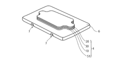
- the present embodiment includes a seating sensor 4 and a pedestal 6 as main components.
- the seating sensor 4 has the same configuration as the seating sensor 1 of the first embodiment, the seating sensor 2 of the second embodiment, or the seating sensor 3 of the third embodiment.
- the shape of the seating sensor 4 shown in FIG. 17 is shown as a shape different from any of the seating sensors in the first to third embodiments for convenience.
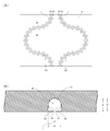
- FIG. 18 is a top view and a sectional view showing the pedestal. Specifically, FIG. 18A is a top view of the pedestal as viewed from one side, and FIG. 18B is a cross-sectional view taken along the line WW in FIG. FIG.
- the pedestal 6 is a member that can be attached to and detached from a part of the two springs stretched over the seat frame, and mounts the seating sensor 4 above the springs.
- the pedestal 6 is a flexible resin plate, and a cushion member 51 (FIG. 17) of the seating sensor 4 is provided on one of the wide surfaces of the pedestal 6 via an adhesive. Further, a groove 7 is formed on one surface of the base 6 opposite to the side on which the cushion member 51 is provided.
- the groove 7 is formed to have a space SP that can be fitted into each of the two springs stretched over the seat frame.
- the formation direction of the groove 7 in the present embodiment is formed corresponding to the formation direction of the two spring parts stretched adjacent to the seat frame, and both ends of the groove 7 are opened at the side surfaces of the base 6. . Therefore, the groove 7 can fit the spring part in the middle of the spring stretched along the bottom surface of the cushion pad into one surface of the base 6, and the spring part is formed in the base 6. It becomes possible to grasp intuitively by the formation direction of the groove 7.
- the bottom 7a of the vertical cross section of the groove 7 has the same shape as the semicircular arc shape of the vertical cross section of the spring to be mounted. For this reason, the groove 7 can fit a part of the spring stretched over the seat frame without forming a gap between the spring to be mounted and the surface of the bottom portion 7a.
- the side portions 7b of the groove 7 are parallel to each other, and the distance (groove width) W between them is set to be approximately equal to the diameter of the spring to be mounted.
- the depth D of the groove 7 is greater than the diameter of the spring to be mounted. For this reason, the groove 7 restricts the movement of the spring in the groove width direction. As a result, the rolling of the pedestal 6 disposed above the spring stretched over the seat frame can be significantly reduced by the groove 7.
- a pair of convex portions 8x and 8y projecting inside the space SP of the groove 7 are connected to the edge of the groove 7 in the long direction.
- These convex portions 8x and 8y are made of a resin plate having flexibility, and face each other at the same distance from the center in the longitudinal direction of the groove 7.
- One wide surface of the convex portions 8x and 8y is on the same surface as the wide surface of the base 6 on which the groove 7 is formed.
- the height H between the position of the protrusions 8x and 8y that protrudes most toward the groove 7 and the lowest position of the groove 7 is smaller than the diameter of the spring.
- the force that the convex portions 8x and 8y themselves return to work acts as a force that suppresses the spring portion fitted in the groove 7.
- the convex portions 8x and 8y can greatly reduce the situation in which the spring portion is detached from the groove 7.
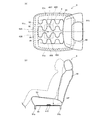
- FIG. 19 is a diagram showing a state of the seat device according to the fourth embodiment of the present invention.
- FIG. 19A is a diagram showing a state of the seat device 90 in which the seating sensor 4 is disposed from above
- FIG. 19B is a diagram of the seat device 90 in which the seating sensor 4 is disposed. It is a figure which shows a mode from the side.
- FIG. 19 shows the pressure sensitive switches 40A to 40D of the seating sensor 3 of the third embodiment for convenience of explanation.
- the seat device 90 includes a seat frame 91, a plurality of springs 95, a seating sensor 4, and a cushion pad 93 and a backrest 96 having the same configuration as that of the first embodiment. .
- the seat frame 91 includes a front frame member 91a arranged as a front part frame, a rear frame member 91b arranged as a rear part frame, and a pair of side frame members arranged as left and right part frames.
- the frame structure includes 91c and 91d.
- the seat frame 91 has an opening surrounded by these members 91a to 91d.
- the front frame member 91a and the side frame members 91c and 91d are made of sheet metal press-molded products, for example.
- the rear frame member 91b is made of, for example, a metal pipe having a circular cross section, and extends in the vehicle width direction. Both ends of the rear frame member 91b are connected to the rear end portions of the side frame members 91c and 91d.
- the plurality of springs 95 are support members that support the cushion pad 93, and are stretched over the seat frame 91 at a predetermined interval from each other.
- Each spring 95 in the present embodiment is a wire having a shape meandering in an S-shape repeatedly on the same surface, the front ends of these springs 95 are attached to the front frame member 91a, and the rear ends of each spring 95 are the rear frame members 91b. Attached to.
- the spring 95 is not limited to an S-shape such as a Z-shape, for example, and various shapes of wire rods in a meandering state can be applied, and a wire rod in a meandering state in which a plurality of shapes are combined can be applied. Further, the spring 95 may be a wire rod meandering continuously in one or a plurality of shapes, or may be a wire rod meandering in one or a plurality of shapes at predetermined intervals, without meandering. A straight wire may be used. Further, in the present embodiment, the plurality of springs 95 are stretched in the front-rear direction, but may be in the left-right direction or in an oblique direction.
- the pedestal 6 on which the seating sensor 4 is placed is disposed on the spring 95 and is sandwiched between the spring 95 and the cushion pad 93.
- the method of disposing the seating sensor 4 on the spring 95 is such that the spring portion corresponding to the groove 7 of the spring 95 is in contact with the convex portions 8x and 8y connected to the longitudinal edge of the groove 7, Push in the pedestal 6.
- the convex portions 8 x and 8 y have flexibility, the open ends of the convex portions 8 x and 8 y bend toward the inner side of the groove 7, and the spring portion enters the groove 7.
- the pedestal 6 is disposed on the spring 95 and the cushion pad 93 is disposed, so that the seating sensor 1 is disposed so as to receive a pressing force from the cushion pad 93 below the cushion pad 93. 93.
- the pressure-sensitive switches 40A to 40D in the seating sensor 4 are respectively arranged in front of the hip point HP.
- the pressure sensitive switches 40 ⁇ / b> A and 40 ⁇ / b> D are arranged along the width direction of the cushion pad so as to avoid a position that is vertically above the spring 95, and are symmetric with respect to the center line L.
- the pressure sensitive switches 40B and 40C are arranged at a position vertically above the spring 95 along the width direction of the cushion pad 93 in front of the pressure sensitive switches 40A and 40D, and symmetrical with respect to the center line L. It is said.
- the terminals 42A and 42B connected to the pressure sensitive switches 40A to 40D are electrically connected to an external power source and a measurement unit (not shown) from below the seat frame 91.
- FIG. 20 is a conceptual diagram showing the distribution of the load that the seat frame and the spring receive via the cushion pad when a person normally sits on the seat device of FIG. Specifically, in FIG. 20, a region that receives the highest pressing force from the cushion pad 93 is indicated by a right oblique line, a region that receives the next highest pressing force is indicated by a left oblique line, and a load applied to the right oblique line and the left oblique line region. A region where a smaller load is applied is indicated by dots.
- the right diagonal line is a line that is substantially parallel to a line that connects the upper right side and the lower left side of the page
- the left diagonal line is a line that is substantially parallel to a line that connects the upper left side and the lower right side of the page.
- the load applied to the spring portion and the seat frame portion (right hatched portion) in front of the hip point HP is larger than the spring portion (left hatched portion) in the vicinity of the hip point HP. .
- the load on the buttocks of a normal seated person and the load on the foot extending in the forward direction from the buttocks work in the vertical direction as well as in the forward direction. I think there is.
- each of the pressure sensitive switches 40A to 40D can appropriately detect the pressing force caused by the seating of the person when the person is seated normally.
- the pressure sensitive switches 40B and 40C are arranged in the region (right hatched portion) that receives the highest pressing force from the cushion pad 93, and the region that receives the next highest pressing force (left hatched portion). ) Are arranged with pressure sensitive switches 40A and 40D. However, in the present embodiment, each of the pressure sensitive switches 40A to 40D receives the highest pressing force from the cushion pad 93 (right hatched portion) or receives the next highest pressing force after that region (left hatched portion). May be arranged.
- the pressure-sensitive switch 40 is provided on the surface opposite to the one surface of the base 6 where the groove 7 that can be fitted into a part of the spring stretched over the seat frame is formed.
- a seating sensor 4 having For this reason, if predetermined portions of a plurality of springs 95 are fitted into the grooves 7, even if the diameter of the springs 95 is small or the space between the springs 95 is large, the springs 95 are connected via the base 6.
- Pressure sensitive switches 40A to 40D can be arranged above. Therefore, the pressure sensitive switches 40A to 40D can be disposed between the spring 95 and the cushion pad 93 placed on the spring 95 in a stable state. Even if the object on which the cushion pad 93 is to be placed is the seat pan 92, the pressure sensitive switches 40A to 40D can be arranged in a stable state.
- the pressure sensitive switches 40A and 40D are arranged at positions avoiding the position on the spring 95 vertically, while the pressure sensitive switches 40B and 40C are positions on the spring 95 vertically. Placed in. Therefore, the force opposed to the pressing force received from the cushion pad 93 is greater in the pressure sensitive switches 40B and 40C on the vertical than the pressure sensitive switches 40A and 40D not on the vertical of the spring 95.
- the openings 34B and 34C of the pressure sensitive switches 40B and 40C are smaller than the openings 34A and 34D of the pressure sensitive switches 40A and 40D, as described above, the pressure sensitive switches 40B and 40C are the pressure sensitive switches 40A and 40D. It is more difficult to turn on.
- pressure-sensitive switches 40B and 40C that are difficult to turn on are disposed at locations that are pressed by a large pressing force, and pressure-sensitive switches 40A and 40D that are easily turned on are disposed at a location that is pressed by a small pressing force. Therefore, even if the pressure sensitive switches 40A to 40D are arranged at a place where an equivalent pressing force is applied from the cushion pad 93, the pressure sensitive switches 40A to 40D themselves can be easily turned on and the pressure sensitive switches 40A to 40D can be turned on. It is possible to cancel the variation with the pressing force applied to the. As a result, the uniformity (balance) at which the pressure sensitive switches 40A to 40D are turned on can be improved.
- the pressure sensitive switches 40A to 40D have a cross section larger than the diameter of the spring 95 which is a wire (the groove width of the groove 7). For this reason, in the pressure sensitive switches 40B and 40C arranged on the vertical side of the spring 95, the portion on the vertical side of the spring 95 tends to be applied with a larger force than the portion not on the vertical side. That is, the distribution of pressure applied to one pressure sensitive switch 40B or 40C tends to be non-uniform. This tendency becomes more prominent as the diameter of the spring 95, which is a wire rod, becomes smaller. On the other hand, since the pressure sensitive switches 40A and 40D are arranged so as to avoid the vertical position of the spring 95, the pressure distribution in the pressure sensitive switch 40A or 40D is substantially uniform.
- the pressure sensitive switches 40A and 40D arranged so as to avoid the vertical position of the spring 95 are more durable than the pressure sensitive switches 40B and 40C arranged on the vertical position of the spring 95. Is reduced. Further, the space around the space over which the spring 95 is stretched is generally closed and the air permeability is poor, so that it is easy to receive heat from the spring 95 generally formed of metal. Therefore, the pressure-sensitive switches 40A and 40D arranged so as to avoid the vertical position of the spring 95 are less durable than the pressure-sensitive switches 40B and 40C arranged on the vertical of the spring 95. Is greatly reduced.
- the force opposed to the pressing force received from the cushion pad 93 is greater in the pressure sensitive switches 40B and 40C on the vertical than the pressure sensitive switches 40A and 40D not on the vertical of the spring 95. growing. For this reason, the sensitivity of the pressure sensitive switches 40B and 40C is better than that of the pressure sensitive switches 40A and 40D.
- an OR circuit is configured by connecting in parallel the pressure sensitive switch 40B (40C) arranged at a position vertically above the spring 95 and the pressure sensitive switch 40A (40D) arranged avoiding the position. It is particularly useful when these OR circuits are connected in series to form an AND-OR. This is because both the advantage of disposing the pressure sensitive switch vertically above the spring 95 and the advantage of disposing the pressure sensitive switch avoiding the position can be obtained equally.
- the cushion member 51 is provided at the bottom of the seating sensor 4 in the seating sensor 4 of the present embodiment, the distribution of the applied pressure to the pressure sensitive switch 40B or 40C that is vertically above the spring 95 becomes non-uniform. Can alleviate this.
- FIG. 21 is a diagram showing a part of the seating sensor and a part of the seating device according to the fifth embodiment of the present invention. Specifically, FIG. 21 is a diagram illustrating a state in the vicinity of the pressure-sensitive switch 40A of the seating sensor 1.
- the seating sensor 1 of the present embodiment is bonded to the bottom surface of the cushion pad 93 with an adhesive AD applied to the surface of the first insulating sheet 11, thereby fixing the cushion pad. It differs from the seating sensor 1 of 1st Embodiment in the point arrange
- the cushion pad 93 may be formed with a recess, and the cushion member 51 may enter the recess so that the cushion member 51 is surrounded by the cushion pad 93.
- the cushion pad 93 is elastically deformed, The cushion member 51 may be surrounded by the cushion pad 93.
- the seating sensor 1 attached to the lower surface of the cushion pad 93 detects the seating of a person as follows. That is, when a person sits on the seat device, the cushion pad 93 is crushed by the load of the person and is bent downward. At this time, the lower surface of the cushion pad 93 bends so that a specific part located in front of the hip point HP is at the lowest side.
- the seating sensor 1 adhered to the lower surface of the cushion pad 93 receives a pressing force from the cushion pad 93 so that the cushion member 51 pressed by the cushion pad 93 enters the opening 34A of the pressure sensitive switch 40A. Deform.
- the second insulating sheet 21 pushed by the cushion member 51 is deformed so as to enter the opening 34A together with the second electrode 24A disposed on the second insulating sheet 21, and the first electrode 14A, the second electrode 24A, Touch.
- the pressure sensitive switch 40A is turned on.
- the pressure sensitive switch 40 ⁇ / b> A bends along the deflection of the lower surface of the cushion pad 93 along the deflection of the lower surface of the cushion pad 93. That is, the first insulating sheet 11 and the second insulating sheet 21 bend in the same direction.
- the second insulating sheet 21 disposed on the cushion pad 93 side is on the inner peripheral side of the bending than the first insulating sheet 11.
- the first electrode 14A and the second electrode 24A are closer due to the difference between the inner and outer circumferences of the first insulating sheet 11 and the second insulating sheet 21.
- the pressure sensitive switch 40A is more easily turned on.
- the other pressure sensitive switches 40B to 40F are also turned on in the same manner.
- the seating sensor 1 and the seating device of the present embodiment since the seating of a person can be detected without a placement member on which the seating sensor 1 is placed, the configuration of the seating device can be simplified.
- the lower side of the seating sensor 1 is a space.
- the insulating sheet 21 on the space side is Although not bent, the insulating sheet 11 on the cushion pad 93 side is bent.
- the hardness of the cushion pad 93 varies depending on the vehicle type and the like, the pressing force that the seating sensor 1 receives from the cushion pad 93 varies depending on the type of the cushion pad 93.
- the cushion member 51 is sandwiched between the cushion pad 93 and the insulating sheet 11, the cushion member 51 is similarly deformed regardless of the hardness of the cushion pad 93. Into the opening 34A of the pressure sensitive switch 40A. Therefore, even when the cushion pad 93 is relatively hard, the insulating sheet can be appropriately bent by the cushion member 51.
- the seating sensor 1 is fixed to the lower surface of the cushion pad 93 by being stuck with the adhesive AD, but the seating sensor 1 may be fixed by other methods.
- the seating sensor 1 may be fixed to the lower surface of the cushion pad 93 with a plurality of pins that penetrate the periphery of each pressure-sensitive switch and are pierced by the cushion pad 93.
- the number of pressure sensitive switches is six.
- the number of pressure sensitive switches in the first embodiment or the second embodiment may be five or less, or may be seven or more.
- the number of pressure sensitive switches is four.
- various numbers can be applied as long as the number of pressure-sensitive switches in the third embodiment is two or more.
- the OR circuit is configured by the pressure-sensitive switch group including the pressure-sensitive switches 40A to 40C and the pressure-sensitive switch group including the pressure-sensitive switches 40D to 40F.
- an AND circuit is configured by the pressure sensitive switch group including the pressure sensitive switches 40A to 40C and the pressure sensitive switch group including the pressure sensitive switches 40D to 40F.
- the pressure sensitive switches 40A to 40F may constitute an OR circuit as a whole, or the pressure sensitive switches 40A to 40F may be connected in series, and the pressure sensitive switches 40A to 40F may constitute an AND circuit.
- the pressure sensitive switches 40A to 40D are connected in series, and the whole of the pressure sensitive switches 40A to 40D constitutes an AND circuit.
- other circuit configurations can be applied to the circuit configurations of the pressure sensitive switches 40A to 40D in the third embodiment.
- each of the pressure sensitive switch group including the pressure sensitive switches 40A and 40B and the pressure sensitive switch group including the pressure sensitive switches 40C and 40D constitutes an OR circuit, and the pressure sensitive switch groups constitute an AND circuit.
- An AND-OR circuit can be used.
- each of the pressure sensitive switches 40A to 40D may constitute an OR circuit.
- the seating sensors 1 to 3, the first electrode sheet 10, the second electrode sheet, and the spacer 30 are substantially H-shaped in the first embodiment and the second embodiment, and the opening is opened in the third embodiment. It was made into the substantially square shape which has. However, various shapes can be applied to the seating sensors 1 to 3, the first electrode sheet 10, the second electrode sheet, and the spacer 30 in the above embodiment. In addition, although the bending amount in the unit area on the basis of the position pressed with a predetermined pressing force is the same in the first insulating sheet 11 and the second insulating sheet 21, it may be different.
- the first electrode and the second electrode in each pressure-sensitive switch have the same shape and size, and are completely overlapped with each other.
- the shape or the like may be different between the first electrode and the second electrode.
- size of the 1st electrode and the 2nd electrode was made slightly larger than an opening, it may be made the same as the said opening, or smaller than an opening.
- the shape of the 1st electrode, the 2nd electrode, and opening was made into circular shape, shapes other than the said circular shape may be sufficient.
- the pair of electrodes (first electrode and second electrode) and the size of the opening in each pressure-sensitive switch have a large diameter (14A, 14D, 24A, 24D, 34A, 34D). And two types having a small diameter (14B, 14C, 24B, 24C, 34B, 34C) are applied, but three or more types may be applied.
- the elastic force in the unit area based on the position pressed with a predetermined pressing force is the same between the cushion member 51 and the cushion pad 93, but may be different.
- the elastic force of the cushion member 51 can be weaker than the elastic force of the cushion pad 93.
- the elastic force of the cushion member 51 can be stronger than the elastic force of the cushion pad 93.
- the cushion pad 93 contracts more than the cushion member 51 when a person is seated, and the cushion member 51 is restrained from contracting. Therefore, the distance from the seat pan 92 to each pressure sensitivity. Can be reduced. Therefore, since the heat transmitted from the seat pan 92 to each pressure sensitive switch can be absorbed by the cushion member 51, it is possible to suppress fluctuations in the pressing force required to turn on the pressure sensitive switch due to temperature. It can suppress that the load which detects seating changes with temperature.
- the thickness which the cushion member 51 is crushed was made into the half or more of the distance between opposing electrodes in each pressure sensitive switch, it was a half of the distance between opposing electrodes in each pressure sensitive switch. It may be smaller.
- the cushion member 51 is provided only on the first insulating sheet 11, but the cushion member may be provided on both the first insulating sheet 11 and the second insulating sheet 21.
- a cushion member 51 as a first cushion member is provided on the opposite side of the first insulating sheet 11 from the spacer 30 side.
- a cushion member 52 as a second cushion member is provided on the opposite side of the second insulating sheet 21 from the spacer 30 side.
- the bending of the insulating sheets 11 and 21 in this manner means that even when the seating sensor is disposed on an object that is not deformed by a load, the seating sensor is disposed on an object that is deformed by the load. Even can be obtained. Therefore, when cushion members are provided on both the first insulating sheet 11 and the second insulating sheet 21, it is possible to suppress the difference in seating detection load depending on the location where the seating sensor is to be disposed. Moreover, since the cushion member 51 or 52 has a property which can be freely changed according to the situation, a gap is generated between the cushion member 51 or 52 and the member facing the cushion member 51 or 52.
- the cushioning members 51 and 52 may have the same or different elastic force in a unit area based on the position pressed with a predetermined pressing force and the thickness at which the cushion member is crushed. Moreover, in the said 3rd Embodiment and 4th Embodiment, the cushion member 51 or 52 is not necessarily required.
- the cushion member 51 that covers the openings 34A to 34F (34A to 34D) in the spacer 30 through the first insulating sheet 11 is applied. It was. However, a cushion member that individually covers each of the openings 34A to 34F (34A to 34D) may be applied. The same applies to the cushion member 52. Further, although the cushion member 51 or 52 covering the entire opening is applied, for example, as shown in FIG. 23, a cushion member 53 covering a part of each of the openings 34A to 34F (34A to 34D) may be applied. Or although not shown in figure, the cushion member which covers a part of opening 34C and 34F (34A and 34D) and covers the whole other opening may be applied.
- any cushion member that covers at least a part of each of the openings 34A to 34F via the first insulating sheet 11 may be used.
- the sensitivity of the pressure sensitive switches 40A to 40F (40A to 40D) can be adjusted by changing the ratio of the cushion member covering the opening (the amount of the cushion member closed relative to the opening) for each different type of opening. For example, either one of the pressure-sensitive switch having the larger opening and the pressure-sensitive switch having the smaller opening is covered with a cushion member, and a part of the other opening is covered with the cushion member.
- the seating sensors 1 to 3 are placed on the seat pan 92, and in the fourth embodiment, the seating sensor 4 is placed on the pedestal 6.
- the mounting member on which the seating sensors 1 to 3 are mounted is not limited to the above embodiment.
- the seat frame 91 is applicable. Specifically, it can be placed on the upper surface of the front frame member 91a, the rear frame member 91b, the side frame member 91c or 91d. As shown in FIG. 20, among these members 91a to 91d, the upper surface of the front frame member 91a receives the highest pressing force from the cushion pad 93.
- the upper surface of the front frame member 91a is the place where the seating sensors 1 to 3 are disposed.
- the pedestal 6 tends to increase.
- the seat pan 92, the upper surface of the seat frame 91, and the like are disposed as the seating sensors 1 to 3.
- the pedestal 6 that can be supported by the two springs 95 is applied.
- a pedestal that can be supported by the bent portion of the single spring 95 may be applied.
- a pedestal for example, one of the pedestals 6 shown in FIG. 18A cut at the center in the longitudinal direction can be cited.
- the pedestal 6 on which the seating sensor 4 is placed above the spring 95 is applied.
- a pedestal on which the seating sensor 4 is placed below the spring 95 may be applied.
- a groove 7 is formed on the seat surface side of the seat, the groove 7 is fitted into a part of two springs 95 from the lower side, and a pedestal on which a seating sensor is placed below the two springs 95 is given. be able to.
- the pressure-sensitive switch may be disposed between adjacent springs, or may be disposed directly below the spring.
- a seating sensor capable of appropriately detecting a person's seating while preventing a sense of incongruity due to the seating sensor, and a seat device using the seating sensor.
Landscapes
- Engineering & Computer Science (AREA)
- Mechanical Engineering (AREA)
- Aviation & Aerospace Engineering (AREA)
- Transportation (AREA)
- Seats For Vehicles (AREA)
- Chair Legs, Seat Parts, And Backrests (AREA)
- Push-Button Switches (AREA)
Abstract
Description
図2は、本発明の第1実施形態に係る着座センサを示す平面図である。図2に示すように、着座センサ1は、第1電極シート10と、第1電極シート10に重ねられる第2電極シート20と、第1電極シート10と第2電極シート20とで挟まれるスペーサと、第1電極シート10のスペーサとは反対側に配置されるクッション部材51を主な構成要素として備える。
次に、本発明の第2実施形態について図11~図13を参照して詳細に説明する。なお、特に説明する場合を除き、第1実施形態と同一又は同等の構成要素については、同一の参照符号を付して、重複する説明は省略する。図11は、本発明の第2実施形態に係る座席装置に用いられる着座センサを示す平面図である。
次に、本発明の第3実施形態について図14~図16を参照して詳細に説明する。なお、特に説明する場合を除き、第1実施形態と同一又は同等の構成要素については、同一の参照符号を付して、重複する説明は省略する。図14は、本発明の第3実施形態に係る着座センサを示す平面図である。
次に、本発明の第4実施形態について図17~図20を参照して詳細に説明する。なお、特に説明する場合を除き、第1実施形態と同一又は同等の構成要素については、同一の参照符号を付して、重複する説明は省略する。
次に、本発明の第5実施形態について図21を参照して詳細に説明する。なお、第1実施形態と同一又は同等の構成要素については、同一の参照符号を付して、特に説明する場合を除き重複する説明は省略する。
6・・・台座
7・・・溝
8x、8y・・・凸部
9、90・・・座席装置
10・・・第1電極シート
11・・・第1絶縁シート
14A~14F・・・第1電極
16A~16M・・・第1配線
20・・・第2電極シート
21・・・第2絶縁シート
24A~24F・・・第2電極
26A~26E・・・第2配線
30・・・スペーサ
34A~34F・・・開口
36A~36F・・・スリット
40A~40F・・・感圧スイッチ
42A、42B・・・端子
51~53・・・クッション部材
91・・・座部フレーム
92・・・シートパン
93・・・クッションパッド
94A、94B・・・孔
95・・・ばね
96・・・背もたれ
Claims (15)
- 座席のクッションパッドの下方に配置される着座センサであって、
可撓性を有する一対の絶縁シートと、
前記一対の絶縁シートの間に介在し、少なくとも1つの開口が形成されたシート状のスペーサと、
前記一対の絶縁シートのそれぞれの表面上に設けられ、前記開口を介して互いに対向する一対の電極と、
前記一対の絶縁シートの少なくとも一方における前記スペーサ側とは反対側に設けられ、前記絶縁シートを介して前記開口の少なくとも一部を覆うクッション部材と、
を備える
ことを特徴とする着座センサ。 - 前記クッション部材は、シリコン、ポリエステルの少なくとも一方を含有する樹脂から成る
ことを特徴とする請求項1に記載の着座センサ。 - 前記クッション部材が潰れる厚さは、前記一対の電極間の距離の半分以上である
ことを特徴とする請求項1または2に記載の着座センサ。 - 前記クッション部材は、
前記一対の絶縁シートいずれか一方の前記絶縁シートにおける前記スペーサ側の面とは反対側の面上に設けられ、前記絶縁シートを介して前記開口の少なくとも一部を覆う第1クッション部材と、
前記第1クッション部材が設けられていない前記絶縁シートにおける前記スペーサ側の面とは反対側の面上に設けられ、前記絶縁シートを介して前記開口の少なくとも一部を覆う第2クッション部材とから成る
ことを特徴とする請求項1~3いずれか1項に記載の着座センサ。 - 前記スペーサには、少なくとも2種類以上の大きさを有する前記開口が形成される
ことを特徴とする請求項1~4いずれか1項に記載の着座センサ。 - 種類が異なる前記開口ごとに、前記クッション部材が前記開口を覆う割合が異なる
ことを特徴とする請求項5に記載の着座センサ。 - 前記請求項1~6のいずれか1項に記載の着座センサと、
クッションパッドと
を備えることを特徴とする座席装置。 - 前記クッションパッドの下方に設けられ、前記着座センサが載置される載置部材
をさらに備え、
前記載置部材と前記絶縁シートとに前記クッション部材が挟まれる状態で、前記載置部材と前記クッションパッドとの間に前記着座センサが配置される
ことを特徴とする請求項7に記載の座席装置。 - 前記載置部材は、前記クッションパッドを支持するシートパンであり、前記シートパンの上面と前記絶縁シートとに前記クッション部材が挟まれる
ことを特徴とする請求項8に記載の座席装置。 - 前記載置部材は、座部フレームに張り渡される複数のばねの一部分に着脱可能とされ、前記着座センサを前記ばねの上方で載置する台座であり、前記台座の座面と前記絶縁シートとに前記クッション部材が挟まれる
ことを特徴とする請求項8に記載の座席装置。 - 前記載置部材は、複数のばねが張り渡される座部フレームであり、前記座部フレームの上面と前記絶縁シートとに前記クッション部材が挟まれる
ことを特徴とする請求項8に記載の座席装置。 - 前記クッション部材が有する弾性力は、前記クッションパッドが有する弾性力よりも弱い
ことを特徴とする請求項7に記載の座席装置。 - 前記クッション部材は、前記クッションパッドと同じ弾性力を有する
ことを特徴とする請求項7に記載の座席装置。 - 前記クッション部材と前記クッションパッドとが同じ材料から成る
ことを特徴とする請求項13に記載の座席装置。 - 前記クッション部材が有する弾性力は、前記クッションパッドが有する弾性力よりも強い
ことを特徴とする請求項7に記載の座席装置。
Priority Applications (3)
| Application Number | Priority Date | Filing Date | Title |
|---|---|---|---|
| CN201180050919.6A CN103180172B (zh) | 2010-10-22 | 2011-10-20 | 就座传感器以及使用就座传感器的座椅装置 |
| EP11834460.5A EP2631114B1 (en) | 2010-10-22 | 2011-10-20 | Seat occupancy sensor and seat device using same |
| JP2012539772A JP5635119B2 (ja) | 2010-10-22 | 2011-10-20 | 着座センサ、及び、それを用いた座席装置 |
Applications Claiming Priority (8)
| Application Number | Priority Date | Filing Date | Title |
|---|---|---|---|
| JP2010237223 | 2010-10-22 | ||
| JP2010237631 | 2010-10-22 | ||
| JP2010-237633 | 2010-10-22 | ||
| JP2010237633 | 2010-10-22 | ||
| JP2010237222 | 2010-10-22 | ||
| JP2010-237631 | 2010-10-22 | ||
| JP2010-237222 | 2010-10-22 | ||
| JP2010-237223 | 2010-10-22 |
Publications (1)
| Publication Number | Publication Date |
|---|---|
| WO2012053621A1 true WO2012053621A1 (ja) | 2012-04-26 |
Family
ID=45975330
Family Applications (2)
| Application Number | Title | Priority Date | Filing Date |
|---|---|---|---|
| PCT/JP2011/074225 Ceased WO2012053621A1 (ja) | 2010-10-22 | 2011-10-20 | 着座センサ、及び、それを用いた座席装置 |
| PCT/JP2011/074224 Ceased WO2012053620A1 (ja) | 2010-10-22 | 2011-10-20 | 座席装置、及び、それに用いる着座センサの配置方法 |
Family Applications After (1)
| Application Number | Title | Priority Date | Filing Date |
|---|---|---|---|
| PCT/JP2011/074224 Ceased WO2012053620A1 (ja) | 2010-10-22 | 2011-10-20 | 座席装置、及び、それに用いる着座センサの配置方法 |
Country Status (4)
| Country | Link |
|---|---|
| EP (2) | EP2631113A4 (ja) |
| JP (2) | JP5635119B2 (ja) |
| CN (2) | CN103180172B (ja) |
| WO (2) | WO2012053621A1 (ja) |
Cited By (6)
| Publication number | Priority date | Publication date | Assignee | Title |
|---|---|---|---|---|
| JP2015031641A (ja) * | 2013-08-06 | 2015-02-16 | 株式会社フジクラ | 感圧センサ |
| CN104487285A (zh) * | 2012-07-25 | 2015-04-01 | 株式会社藤仓 | 座席装置 |
| JP2016225259A (ja) * | 2015-06-04 | 2016-12-28 | 株式会社フジクラ | 把持検出装置及びセンサ |
| CN107054165A (zh) * | 2017-05-18 | 2017-08-18 | 上海安闻汽车电子有限公司 | 一种汽车座椅 |
| CN107097699A (zh) * | 2017-05-18 | 2017-08-29 | 上海安闻汽车电子有限公司 | 一种汽车座椅 |
| CN107150620A (zh) * | 2017-05-18 | 2017-09-12 | 上海安闻汽车电子有限公司 | 一种人体压力传感器及汽车座椅 |
Families Citing this family (18)
| Publication number | Priority date | Publication date | Assignee | Title |
|---|---|---|---|---|
| JP5905413B2 (ja) * | 2013-07-02 | 2016-04-20 | テイ・エス テック株式会社 | 乗物用シート |
| JP5604566B1 (ja) * | 2013-07-05 | 2014-10-08 | 株式会社フジクラ | メンブレンスイッチ及び座席装置 |
| RS20140183A1 (en) | 2014-04-14 | 2015-10-30 | Novelic D.O.O. | RADAR SENSOR FOR SEAT CONVENIENCE DETECTION OPERATING IN THE MILLIMETER FREQUENCY RANGE AND METHOD OF OPERATION |
| FR3024683B1 (fr) | 2014-08-08 | 2018-02-23 | Faurecia Sieges D'automobile | Dispositif thermique pour siege de vehicule automobile |
| CN104297801A (zh) * | 2014-09-24 | 2015-01-21 | 昆山腾朗电子有限公司 | 一种车用感应器 |
| JP6500704B2 (ja) * | 2015-09-01 | 2019-04-17 | トヨタ紡織株式会社 | センサ部材 |
| WO2017135263A1 (ja) * | 2016-02-05 | 2017-08-10 | テイ・エス テック株式会社 | 生体情報計測装置 |
| JP6627697B2 (ja) * | 2016-09-12 | 2020-01-08 | 株式会社デンソー | 乗員検知装置 |
| US10618438B2 (en) | 2016-10-21 | 2020-04-14 | Faurecia Automotive Seating, Llc | Vehicle seat with a thermal device |
| WO2018124197A1 (ja) * | 2016-12-28 | 2018-07-05 | 株式会社フジクラ | 荷重検知センサユニット |
| JP6583325B2 (ja) | 2017-03-24 | 2019-10-02 | テイ・エス テック株式会社 | 乗物用シート |
| JP6309130B1 (ja) | 2017-03-24 | 2018-04-11 | テイ・エス テック株式会社 | 乗物用シート |
| JP7022274B2 (ja) * | 2017-10-06 | 2022-02-18 | テイ・エス テック株式会社 | 着座センサ |
| JP2019182329A (ja) * | 2018-04-16 | 2019-10-24 | テイ・エス テック株式会社 | シートへのセンサーの配置構造及び車両用シート |
| JP7212918B2 (ja) * | 2018-08-24 | 2023-01-26 | 株式会社タイカ | 着座用クッション及び椅子用座面 |
| AU2019343825B2 (en) * | 2018-09-19 | 2022-08-04 | Mitsui Chemicals, Inc. | Human body detection device, bed device, and human body detection system |
| JP7223034B2 (ja) * | 2019-01-04 | 2023-02-15 | 株式会社フジクラ | 着座センサ及び座席装置 |
| CN114593847A (zh) * | 2022-03-24 | 2022-06-07 | 轻昂化学(深圳)有限公司 | 串联连接的柔性传感器结构 |
Citations (6)
| Publication number | Priority date | Publication date | Assignee | Title |
|---|---|---|---|---|
| JPH09315199A (ja) | 1996-05-29 | 1997-12-09 | Aisin Seiki Co Ltd | 着座検知装置 |
| JP2001180353A (ja) * | 1999-12-27 | 2001-07-03 | Nhk Spring Co Ltd | 自動車シートの着座感知装置 |
| JP2005315745A (ja) * | 2004-04-28 | 2005-11-10 | Denso Corp | 車両用着座センサ |
| JP2008183977A (ja) * | 2007-01-29 | 2008-08-14 | Toyota Boshoku Corp | 車両用シート |
| JP2009113789A (ja) * | 2007-10-16 | 2009-05-28 | Takata Corp | シートベルトバックル装置 |
| JP2010125122A (ja) * | 2008-11-28 | 2010-06-10 | Toyota Boshoku Corp | 緩衝体付き乗物用シート |
Family Cites Families (7)
| Publication number | Priority date | Publication date | Assignee | Title |
|---|---|---|---|---|
| JP2002144936A (ja) * | 2000-11-08 | 2002-05-22 | Nhk Spring Co Ltd | 自動車シートの着座感知装置 |
| JP2003045274A (ja) * | 2001-07-31 | 2003-02-14 | Fujikura Ltd | 着座センサ |
| CN100496337C (zh) * | 2003-06-03 | 2009-06-10 | 株式会社普利司通 | 带就座传感器的座席及座席用衬垫 |
| KR100599561B1 (ko) * | 2004-12-20 | 2006-07-13 | 현대모비스 주식회사 | 차량 탑승객의 착석 상태 측정 장치 |
| EP1683684A1 (en) * | 2005-01-21 | 2006-07-26 | IEE INTERNATIONAL ELECTRONICS & ENGINEERING S.A. | Checkable seat occupancy sensor |
| DE102005016974A1 (de) * | 2005-04-13 | 2006-10-19 | Ford Global Technologies, LLC, Dearborn | Sitz, insbesondere Fahrzeugsitz |
| US20090094807A1 (en) * | 2007-10-16 | 2009-04-16 | Takata Corporation | Seatbelt buckle apparatus |
-
2011
- 2011-10-20 CN CN201180050919.6A patent/CN103180172B/zh active Active
- 2011-10-20 JP JP2012539772A patent/JP5635119B2/ja active Active
- 2011-10-20 EP EP11834459.7A patent/EP2631113A4/en not_active Withdrawn
- 2011-10-20 JP JP2012539771A patent/JP5646642B2/ja active Active
- 2011-10-20 WO PCT/JP2011/074225 patent/WO2012053621A1/ja not_active Ceased
- 2011-10-20 WO PCT/JP2011/074224 patent/WO2012053620A1/ja not_active Ceased
- 2011-10-20 CN CN201180050906.9A patent/CN103189234B/zh active Active
- 2011-10-20 EP EP11834460.5A patent/EP2631114B1/en active Active
Patent Citations (6)
| Publication number | Priority date | Publication date | Assignee | Title |
|---|---|---|---|---|
| JPH09315199A (ja) | 1996-05-29 | 1997-12-09 | Aisin Seiki Co Ltd | 着座検知装置 |
| JP2001180353A (ja) * | 1999-12-27 | 2001-07-03 | Nhk Spring Co Ltd | 自動車シートの着座感知装置 |
| JP2005315745A (ja) * | 2004-04-28 | 2005-11-10 | Denso Corp | 車両用着座センサ |
| JP2008183977A (ja) * | 2007-01-29 | 2008-08-14 | Toyota Boshoku Corp | 車両用シート |
| JP2009113789A (ja) * | 2007-10-16 | 2009-05-28 | Takata Corp | シートベルトバックル装置 |
| JP2010125122A (ja) * | 2008-11-28 | 2010-06-10 | Toyota Boshoku Corp | 緩衝体付き乗物用シート |
Non-Patent Citations (1)
| Title |
|---|
| See also references of EP2631114A4 |
Cited By (7)
| Publication number | Priority date | Publication date | Assignee | Title |
|---|---|---|---|---|
| CN104487285A (zh) * | 2012-07-25 | 2015-04-01 | 株式会社藤仓 | 座席装置 |
| EP2878483A4 (en) * | 2012-07-25 | 2016-04-06 | Fujikura Ltd | Seat device |
| JP2015031641A (ja) * | 2013-08-06 | 2015-02-16 | 株式会社フジクラ | 感圧センサ |
| JP2016225259A (ja) * | 2015-06-04 | 2016-12-28 | 株式会社フジクラ | 把持検出装置及びセンサ |
| CN107054165A (zh) * | 2017-05-18 | 2017-08-18 | 上海安闻汽车电子有限公司 | 一种汽车座椅 |
| CN107097699A (zh) * | 2017-05-18 | 2017-08-29 | 上海安闻汽车电子有限公司 | 一种汽车座椅 |
| CN107150620A (zh) * | 2017-05-18 | 2017-09-12 | 上海安闻汽车电子有限公司 | 一种人体压力传感器及汽车座椅 |
Also Published As
| Publication number | Publication date |
|---|---|
| EP2631114B1 (en) | 2020-04-08 |
| CN103180172A (zh) | 2013-06-26 |
| JPWO2012053621A1 (ja) | 2014-02-24 |
| EP2631113A4 (en) | 2017-03-29 |
| WO2012053620A1 (ja) | 2012-04-26 |
| CN103189234A (zh) | 2013-07-03 |
| EP2631114A4 (en) | 2017-08-02 |
| CN103189234B (zh) | 2016-10-05 |
| JP5635119B2 (ja) | 2014-12-03 |
| EP2631113A1 (en) | 2013-08-28 |
| JPWO2012053620A1 (ja) | 2014-02-24 |
| JP5646642B2 (ja) | 2014-12-24 |
| EP2631114A1 (en) | 2013-08-28 |
| CN103180172B (zh) | 2016-04-20 |
Similar Documents
| Publication | Publication Date | Title |
|---|---|---|
| JP5635119B2 (ja) | 着座センサ、及び、それを用いた座席装置 | |
| JP5747078B2 (ja) | 着座センサ及び座席装置 | |
| JP5324548B2 (ja) | 着座センサ、及び、それを用いた座席装置 | |
| JP5520012B2 (ja) | 着座センサ | |
| JP5635118B2 (ja) | 着座センサ、及び、それを用いた座席装置 | |
| JP5243639B1 (ja) | 座席装置 | |
| JP2012108113A (ja) | 着座センサ、及び、それを用いた座席装置 | |
| JP2013016285A (ja) | 着座センサ | |
| JP2012121364A (ja) | 着座センサ、及び、それを用いた座席装置 | |
| JP2012106724A (ja) | 着座センサ、及び、それを用いた座席装置 | |
| JP2013014183A (ja) | 着座センサ | |
| JP5604257B2 (ja) | 座席装置 | |
| JP5782310B2 (ja) | 座席装置 | |
| JP5844211B2 (ja) | 着座センサユニット及び座席装置 | |
| JP5738694B2 (ja) | 着座センサ及び座席装置 | |
| JP5604277B2 (ja) | 着座センサ、及び、それを用いた座席装置 | |
| JP2013014180A (ja) | 座席装置 | |
| JP2012086805A (ja) | 着座センサ、及び、それを用いた座席装置 | |
| JP2016114494A (ja) | 静電容量型センサ | |
| JPWO2014017563A1 (ja) | 座席装置 |
Legal Events
| Date | Code | Title | Description |
|---|---|---|---|
| WWE | Wipo information: entry into national phase |
Ref document number: 201180050919.6 Country of ref document: CN |
|
| 121 | Ep: the epo has been informed by wipo that ep was designated in this application |
Ref document number: 11834460 Country of ref document: EP Kind code of ref document: A1 |
|
| ENP | Entry into the national phase |
Ref document number: 2012539772 Country of ref document: JP Kind code of ref document: A |
|
| NENP | Non-entry into the national phase |
Ref country code: DE |
|
| WWE | Wipo information: entry into national phase |
Ref document number: 2011834460 Country of ref document: EP |