WO2012057004A1 - フィルムミラー、フィルムミラーの製造方法及び太陽熱発電用反射装置 - Google Patents
フィルムミラー、フィルムミラーの製造方法及び太陽熱発電用反射装置 Download PDFInfo
- Publication number
- WO2012057004A1 WO2012057004A1 PCT/JP2011/074226 JP2011074226W WO2012057004A1 WO 2012057004 A1 WO2012057004 A1 WO 2012057004A1 JP 2011074226 W JP2011074226 W JP 2011074226W WO 2012057004 A1 WO2012057004 A1 WO 2012057004A1
- Authority
- WO
- WIPO (PCT)
- Prior art keywords
- film
- film mirror
- layer
- resin
- silver
- Prior art date
- Legal status (The legal status is an assumption and is not a legal conclusion. Google has not performed a legal analysis and makes no representation as to the accuracy of the status listed.)
- Ceased
Links
Images
Classifications
-
- G—PHYSICS
- G02—OPTICS
- G02B—OPTICAL ELEMENTS, SYSTEMS OR APPARATUS
- G02B5/00—Optical elements other than lenses
- G02B5/08—Mirrors
- G02B5/0808—Mirrors having a single reflecting layer
-
- G—PHYSICS
- G02—OPTICS
- G02B—OPTICAL ELEMENTS, SYSTEMS OR APPARATUS
- G02B5/00—Optical elements other than lenses
- G02B5/08—Mirrors
-
- F—MECHANICAL ENGINEERING; LIGHTING; HEATING; WEAPONS; BLASTING
- F24—HEATING; RANGES; VENTILATING
- F24S—SOLAR HEAT COLLECTORS; SOLAR HEAT SYSTEMS
- F24S23/00—Arrangements for concentrating solar-rays for solar heat collectors
- F24S23/70—Arrangements for concentrating solar-rays for solar heat collectors with reflectors
-
- G02B1/105—
-
- G—PHYSICS
- G02—OPTICS
- G02B—OPTICAL ELEMENTS, SYSTEMS OR APPARATUS
- G02B1/00—Optical elements characterised by the material of which they are made; Optical coatings for optical elements
- G02B1/10—Optical coatings produced by application to, or surface treatment of, optical elements
- G02B1/14—Protective coatings, e.g. hard coatings
-
- F—MECHANICAL ENGINEERING; LIGHTING; HEATING; WEAPONS; BLASTING
- F24—HEATING; RANGES; VENTILATING
- F24S—SOLAR HEAT COLLECTORS; SOLAR HEAT SYSTEMS
- F24S23/00—Arrangements for concentrating solar-rays for solar heat collectors
- F24S23/70—Arrangements for concentrating solar-rays for solar heat collectors with reflectors
- F24S2023/86—Arrangements for concentrating solar-rays for solar heat collectors with reflectors in the form of reflective coatings
-
- Y—GENERAL TAGGING OF NEW TECHNOLOGICAL DEVELOPMENTS; GENERAL TAGGING OF CROSS-SECTIONAL TECHNOLOGIES SPANNING OVER SEVERAL SECTIONS OF THE IPC; TECHNICAL SUBJECTS COVERED BY FORMER USPC CROSS-REFERENCE ART COLLECTIONS [XRACs] AND DIGESTS
- Y02—TECHNOLOGIES OR APPLICATIONS FOR MITIGATION OR ADAPTATION AGAINST CLIMATE CHANGE
- Y02E—REDUCTION OF GREENHOUSE GAS [GHG] EMISSIONS, RELATED TO ENERGY GENERATION, TRANSMISSION OR DISTRIBUTION
- Y02E10/00—Energy generation through renewable energy sources
- Y02E10/40—Solar thermal energy, e.g. solar towers
Definitions
- the present invention relates to a film mirror having a good regular reflectance with respect to sunlight, a method for producing the film mirror, and a solar power generation reflector using the film mirror.
- a glass mirror Since the reflection device is exposed to ultraviolet rays and heat from sunlight, wind and rain, sandstorms, and the like, conventionally, a glass mirror has been used. Glass mirrors have high environmental durability, but they are damaged during transportation, and because of their large mass, there is a problem in that the construction cost of the plant is increased due to the strength of the frame on which the mirror is installed. Furthermore, glass mirrors are easily damaged, and care must be taken not to injure the damaged part during replacement. Further, glass mirrors are often installed outdoors, and are affected by the working environment (wind, rain, sand, dust, etc.), so skill is required for the replacement work.
- the metal layer serving as the reflective surface is made of silver having a high reflectance in the visible light region.
- silver has the disadvantage of being easily corroded by environmental factors. Therefore, a design is made to protect the silver by providing a resin layer between the sunlight incident side and the silver layer.
- the glass mirror when the glass mirror is replaced with a resinous reflective sheet or a thinner reflective film, it can be wound in a roll shape, so that continuous film formation is possible, and production efficiency can be greatly increased.
- the resinous film has a drawback that the film surfaces stick to each other and deform compared to glass.
- the films stick to each other in a mottled manner, causing deformation of the film and a change in film thickness.
- a surface treatment for improving slipperiness is performed. For example, there is a method of embossing both ends of the film or forming surface irregularities by mixing particles. However, the portions embossed on both ends are not used for the final product but are cut and discarded during production, resulting in production loss.
- the present invention has been made in view of the above problems, and its purpose is to be lightweight and flexible, to reduce the manufacturing cost, to increase the area and mass production, and to provide good regular reflectance with respect to sunlight. And a film mirror that is difficult to stick and easy to handle when wound into a roll in the manufacturing process. Moreover, it is providing the manufacturing apparatus of the film mirror, and the solar power generation reflective apparatus using the film mirror.
- a film mirror in which at least an adhesive layer, a silver reflective layer, and a protective layer are provided in this order as constituent layers on a resin base material, and the surface roughness on the light incident side of the resin base material, the silver reflective layer, and the protective layer A film mirror having a thickness Ra of 0.005 to 0.04 ⁇ m.
- the present invention is lightweight and flexible, can reduce the manufacturing cost, can be increased in area and mass-produced, has a good regular reflectance with respect to sunlight, and is applied when wound into a roll in the manufacturing process. It was possible to provide a film mirror that is difficult to attach and easy to handle. Moreover, the manufacturing method of the film mirror and the solar power generation reflective apparatus using the film mirror could be provided.
- the film mirror of the present invention is a film mirror in which at least an adhesive layer, a silver reflective layer, and a protective layer are provided in this order as constituent layers on a resin base material, and the resin base material, the silver reflective layer, and the protective layer
- the surface roughness Ra on the light incident side is 0.005 to 0.04 ⁇ m.
- the surface roughness Ra on the light incident side of the resin base material, the silver reflective layer, and the protective layer is set to 0.005 to 0.04 ⁇ m, thereby suppressing the decrease in the reflectance of the silver reflective layer.
- the surface roughness Ra on the light incident side of the resin base material, the silver reflective layer and the protective layer is more preferably from 0.01 to 0.03.
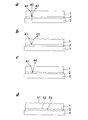
- FIG. 1A is a diagram showing a basic configuration and light reflection of a film mirror.
- Incident light 41 entering from the protective layer 1 side onto the film mirror in which the adhesive layer (not shown), the silver reflection layer 2 and the protective layer 1 are provided in this order on the resin base material 3 passes through the incident optical path and is silver. Reflected by the surface of the reflective layer 2, the reflected light 42 goes out of the protective layer 1 through the reflected light path.
- the surface of the protective layer 1 is not smooth as shown in FIG. 1 b
- the reflected light 43 reflected on the surface of the silver reflective layer 2 is scattered on the surface of the protective layer 1.
- the incident light 41 is reflected by the surface of the silver reflective layer 2, and the reflected light 44 is scattered.
- the present inventor has developed a surface roughness Ra which is a measure of the surface smoothness of the light incident side of the resin base material, the silver reflective layer and the protective layer, the regular reflectance of the film mirror, the resin base material (film shape), and the film mirror.
- the relationship between slipperiness and slipperiness was investigated.
- the regular reflectance it was found that when the surface roughness Ra on the light incident side of the resin base material, the silver reflective layer, and the protective layer is 0.04 ⁇ m or less, the decrease in regular reflectance due to scattering is small.
- slipperiness it was found that good slipperiness can be obtained if the surface roughness Ra of the resin base material and the protective layer is 0.005 ⁇ m or more.
- a film mirror in which at least an adhesive layer, a silver reflective layer, and a protective layer are provided in this order as constituent layers on the resin base material, and the light incident side of the resin base material, the silver reflective layer, and the protective layer It has been found that by setting the surface roughness Ra to 0.005 to 0.04 ⁇ m, a film mirror having both regular reflectance, difficulty of sticking, and ease of handling can be obtained.
- a gas barrier layer on the side of the protective layer where no silver reflective layer is present, from the viewpoint of manifesting the effects of the present invention.
- the film mirror manufacturing method for manufacturing the film mirror of the present invention is preferably a manufacturing method having an aspect including a step of forming a silver reflective layer by silver vapor deposition.
- the metal substrate is interposed through an adhesive layer coated on the resin substrate surface opposite to the side having the silver reflecting layer. It is preferable that it is the solar power generation reflective apparatus of the aspect formed by affixing the said film mirror on a base material.
- the film mirror of the present invention is a film mirror in which at least an adhesive layer, a silver reflective layer, and a protective layer are provided in this order as constituent layers on a resin substrate.
- a special functional layer such as a gas barrier layer or a scratch prevention layer as the constituent layer.
- the present invention is characterized in that the surface roughness Ra of the light incident side of the resin base material is 0.005 to 0.04 ⁇ m.
- the surface roughness can be measured by a general method. For example, it can be carried out with a Weeko NT9300 optical profiler manufactured by Veeco or an ultra-high-precision three-dimensional measuring machine (UA3P) manufactured by Panasonic.
- a Weeko NT9300 optical profiler manufactured by Veeco
- U3P ultra-high-precision three-dimensional measuring machine
- the resin substrate is also a rigid body for maintaining the surface accuracy of the film mirror, and the surface roughness of the resin substrate opposite to the light incidence is preferably in the range of 15 to 100 nm.
- the surface roughness of the resin substrate opposite to the light incidence is preferably in the range of 15 to 100 nm.
- resin films can be used as the resin base material according to the present invention.
- a polyester film or a cellulose ester film it is preferable to use a polyester film or a cellulose ester film, and it may be a film manufactured by melt casting or a film manufactured by solution casting.
- the thickness of the resin base material is preferably an appropriate thickness depending on the type and purpose of the resin. For example, it is generally in the range of 10 to 300 ⁇ m. The thickness is preferably 20 to 200 ⁇ m, more preferably 30 to 100 ⁇ m.
- the adhesive layer according to the present invention is not particularly limited as long as it has a function of enhancing the adhesion between the silver reflective layer and the resin base material (resin film), but is preferably made of a resin. Therefore, the adhesive layer has adhesiveness for closely adhering the resin base material (resin film) and the silver reflective layer, heat resistance that can withstand heat when the silver reflective layer is formed by a vacuum deposition method, and the silver reflective layer. Smoothness is required to bring out the high reflection performance inherent in
- the resin used as the binder for the adhesive layer is not particularly limited as long as it satisfies the above conditions of adhesion, heat resistance, and smoothness.
- Polyester resin, acrylic resin, melamine resin, epoxy Resin, polyamide resin, vinyl chloride resin, vinyl chloride vinyl acetate copolymer resin or the like can be used alone or a mixed resin thereof. From the viewpoint of weather resistance, a polyester resin and a melamine resin mixed resin are preferable. Furthermore, it is more preferable to use a thermosetting resin mixed with a curing agent such as isocyanate.
- the thickness of the adhesive layer is preferably from 0.01 to 3 ⁇ m, more preferably from 0.1 to 1 ⁇ m, from the viewpoints of adhesion, smoothness, reflectance of the reflecting material, and the like.
- a method for forming the adhesive layer conventionally known coating methods such as a gravure coating method, a reverse coating method, and a die coating method can be used.
- the present invention is characterized in that the surface roughness Ra on the light incident side of the silver reflective layer is 0.005 to 0.04 ⁇ m.
- the resin base material is in contact with the thin silver reflective layer through the adhesive layer and affects the roughness of the surface of the silver reflective layer.
- the surface roughness can be measured by a general method.
- it can be carried out using a Wyko NT9300 optical profiler manufactured by Veeco, an ultra-high precision three-dimensional measuring machine (UA3P) manufactured by Panasonic, or the like.
- U3P ultra-high precision three-dimensional measuring machine
- Both the wet method and the dry method can be used as the method for forming the silver reflective layer according to the present invention.
- the wet method is a general term for a plating method, and is a method of forming a film by depositing a metal from a solution. Specific examples include silver mirror reaction.
- the dry method is a general term for a vacuum film-forming method.
- Specific examples include a resistance heating vacuum deposition method, an electron beam heating vacuum deposition method, an ion plating method, and an ion beam assisted vacuum deposition method.
- sputtering method a vapor deposition method capable of a roll-to-roll method for continuously forming a film is preferably used in the present invention. That is, it is preferable that it is a manufacturing method of the aspect which has the process of forming the said silver reflection layer by silver vapor deposition as a manufacturing method of the film mirror which manufactures the film mirror of this invention.
- the thickness of the silver reflective layer is preferably 10 to 200 nm, more preferably 30 to 150 nm, from the viewpoint of reflectivity and the like.
- the silver reflective layer may be on the light incident side or on the opposite side with respect to the support, but since the support is a resin, for the purpose of preventing resin degradation due to light, It is preferable to be positioned on the light incident side.
- the present invention is characterized in that the protective layer has a surface roughness Ra of 0.005 to 0.04 ⁇ m.
- a method for adjusting the surface roughness Ra on the light incident side of the resin base material as a lower layer, a method using a filler, and leveling during film formation are performed. There are methods to adjust.
- the surface roughness can be measured by a general method.
- it can be carried out using a Wyko NT9300 optical profiler manufactured by Veeco, an ultra-high precision three-dimensional measuring machine (UA3P) manufactured by Panasonic, or the like.
- U3P ultra-high precision three-dimensional measuring machine
- the protective layer used in the film mirror of the present invention is adjacent to the side of the silver reflective layer that is far from the resin base material (support), prevents the silver reflective layer from being scratched, and has a barrier layer and a scratch preventive layer outside the protective layer. In the case of forming, it contributes to the improvement of the adhesive strength with the barrier layer and the scratch-preventing layer.
- the resin used as the binder for the protective layer may be a polyester resin, an acrylic resin, a melamine resin, an epoxy resin, or a mixture of these resins. From the viewpoint of weather resistance, a polyester resin or an acrylic resin may be used. A resin is preferable, and a thermosetting resin in which a curing agent such as isocyanate is further mixed is more preferable.
- isocyanate various conventionally used isocyanates such as TDI (tolylene diisocyanate), XDI (xylene diisocyanate), MDI (methylene diisocyanate), and HMDI (hexamethylene diisocyanate) can be used. From the viewpoint of properties, XDI, MDI, and HMDI isocyanates are preferably used.
- the thickness of the protective layer is preferably from 0.01 to 3 ⁇ m, more preferably from 0.1 to 1 ⁇ m, from the viewpoints of adhesion, weather resistance and the like.
- a method for forming the protective layer conventionally known coating methods such as a gravure coating method, a reverse coating method, and a die coating method can be used.
- the film mirror of this invention can use the corrosion inhibitor of a silver reflection layer for a structural layer.
- the corrosion inhibitor it is preferable to use a corrosion inhibitor which is a heterocyclic compound having adsorptivity to silver and has a melting point of 25 ° C. or higher.
- corrosion refers to a phenomenon in which metal (silver) is chemically or electrochemically eroded or deteriorated by the environmental material surrounding it (see JIS Z0103-2004).
- the optimum amount of the corrosion inhibitor varies depending on the compound to be used, but generally it is preferably within the range of 0.1 to 1.0 / m 2 .
- ⁇ Heterocyclic compound with adsorptivity to silver> As a corrosion inhibitor having an adsorption property to silver and a melting point of 25 ° C. or more, a compound having a pyrrole ring, a compound having a triazole ring, a compound having a pyrazole ring, a thiazole ring It is desirable that the compound be selected from at least one of a compound having an imidazole ring, a compound having an indazole ring, a heterocyclic compound having a mercapto group, or a mixture thereof.
- corrosion inhibitor having a adsorptivity to silver used in the present invention and having a melting point of 25 ° C. or higher include the following compounds.
- Examples of the compound having a pyrrole ring include N-butyl-2,5-dimethylpyrrole, N-phenyl-2,5dimethylpyrrole, N-phenyl-3-formyl-2,5-dimethylpyrrole, N-phenyl-3, 4-diformyl-2,5-dimethylpyrrole, etc., or a mixture thereof.
- Examples of the compound having a triazole ring include 1,2,3-triazole, 1,2,4-triazole, 3-mercapto-1,2,4-triazole, 3-hydroxy-1,2,4-triazole, 3- Methyl-1,2,4-triazole, 1-methyl-1,2,4-triazole, 1-methyl-3-mercapto-1,2,4-triazole, 4-methyl-1,2,3-triazole, Benzotriazole, tolyltriazole, 1-hydroxybenzotriazole, 4,5,6,7-tetrahydrotriazole, 3-amino-1,2,4-triazole, 3-amino-5-methyl-1,2,4- Triazole, carboxybenzotriazole, 2- (2'-hydroxy-5'-methylphenyl) benzotriazole, 2- (2'-hydroxy) -5'-tert-butylphenyl) benzotriazole, 2- (2'-hydroxy3'5'-di-tert-butylphenyl) benzotriazole, 2-
- Examples of the compound having a pyrazole ring include pyrazole, pyrazoline, pyrazolone, pyrazolidine, pyrazolidone, 3,5-dimethylpyrazole, 3-methyl-5-hydroxypyrazole, 4-aminopyrazole, and a mixture thereof.
- Examples of the compound having a thiazole ring include thiazole, thiazoline, thiazolone, thiazolidine, thiazolidone, isothiazole, benzothiazole, 2-N, N-diethylthiobenzothiazole, P-dimethylaminobenzallodanine, 2-mercaptobenzothiazole, etc. Or a mixture thereof.
- Compounds having an imidazole ring include imidazole, histidine, 2-heptadecylimidazole, 2-methylimidazole, 2-ethyl-4-methylimidazole, 2-phenylimidazole, 2-undecylimidazole, 1-benzyl-2-methyl.
- Imidazole 2-phenyl-4-methylimidazole, 1-cyanoethyl-2-methylimidazole, 1-cyanoethyl-2-phenylimidazole, 1-cyanoethyl-2-ethyl-4-methylimidazole, 1-cyanoethyl-2-undecyl Imidazole, 2-phenyl-4-methyl-5-hydromethylimidazole, 2-phenyl-4,5 dihydroxymethylimidazole, 4-formylimidazole, 2-methyl-4-formylimidazole, 2-phenyl-4- Formylimidazole, 4-methyl-5-formylimidazole, 2-ethyl-4-methyl-5-formylimidazole, 2-phenyl-4-methyl-4-formylimidazole, 2-mercaptobenzimidazole, etc. These mixtures are mentioned.
- Examples of the compound having an indazole ring include 4-chloroindazole, 4-nitroindazole, 5-nitroindazole, 4-chloro-5-nitroindazole, and a mixture thereof.
- thioureas examples include thiourea, guanylthiourea, and the like, or a mixture thereof.
- an antioxidant may be added to the constituent layer in the film mirror of the present invention.
- the antioxidant it is preferable to use a phenol-based antioxidant, a thiol-based antioxidant, and a phosphite-based antioxidant.
- phenolic antioxidants examples include 1,1,3-tris (2-methyl-4-hydroxy-5-tert-butylphenyl) butane, 2,2′-methylenebis (4-ethyl-6-t- Butylphenol), tetrakis- [methylene-3- (3 ′, 5′-di-t-butyl-4′-hydroxyphenyl) propionate] methane, 2,6-di-t-butyl-p-cresol, 4,4 '-Thiobis (3-methyl-6-t-butylphenol), 4,4'-butylidenebis (3-methyl-6-t-butylphenol), 1,3,5-tris (3', 5'-di-t -Butyl-4'-hydroxybenzyl) -S-triazine-2,4,6- (1H, 3H, 5H) trione, stearyl- ⁇ - (3,5-di-t-butyl-4-hydroxyphenyl) propi , Triethylene glycol bis [3- (3-
- thiol-based antioxidant examples include distearyl-3,3′-thiodipropionate, pentaerythritol-tetrakis- ( ⁇ -lauryl-thiopropionate), and the like.
- phosphite antioxidant examples include tris (2,4-di-t-butylphenyl) phosphite, distearyl pentaerythritol diphosphite, di (2,6-di-t-butylphenyl) pentaerythritol.
- Diphosphite bis- (2,6-di-t-butyl-4-methylphenyl) -pentaerythritol diphosphite, tetrakis (2,4-di-t-butylphenyl) 4,4'-biphenylene-diphosphonite 2,2'-methylenebis (4,6-di-t-butylphenyl) octyl phosphite and the like.
- the above antioxidant and the following light stabilizer can be used in combination.
- hindered amine light stabilizers include bis (2,2,6,6-tetramethyl-4-piperidyl) sebacate, bis (1,2,2,6,6-pentamethyl-4-piperidyl) sebacate, Bis (1,2,2,6,6-pentamethyl-4-piperidyl) -2- (3,5-di-t-butyl-4-hydroxybenzyl) -2-n-butylmalonate, 1-methyl- 8- (1,2,2,6,6-pentamethyl-4-piperidyl) -sebacate, 1- [2- [3- (3,5-di-tert-butyl-4-hydroxyphenyl) propionyloxy] ethyl ] -4- [3- (3,5-di-tert-butyl-4-hydroxyphenyl) propionyloxy] -2,2,6,6-tetramethylpiperidine, 4-benzoyloxy-2,2,6, 6-Tetrame Lupiperidine, tetrakis (2,2,2,
- nickel-based UV stabilizers include [2,2'-thiobis (4-t-octylphenolate)]-2-ethylhexylamine nickel (II), nickel complex-3,5-di-t-butyl-4- Hydroxybenzyl phosphate monoethylate, nickel dibutyl dithiocarbamate, etc. can also be used.
- a hindered amine light stabilizer containing only a tertiary amine is preferable.
- bis (1,2,2,6,6-pentamethyl-4-piperidyl) is preferable.
- a condensate of 1,2,2,6,6-pentamethyl-4-piperidinol / tridecyl alcohol and 1,2,3,4-butanetetracarboxylic acid is preferred.
- gas barrier layer In the film mirror of the present invention, it is also preferable to further provide a gas barrier layer.
- the gas barrier layer is intended to prevent deterioration of humidity, especially deterioration of the resin base material and various functional elements protected by the resin base material due to high humidity, but with special functions and applications. As long as the above characteristics are maintained, various types of gas barrier layers can be provided.
- the water vapor permeability at 40 ° C. and 90% RH is 100 g / m 2 ⁇ day / ⁇ m or less, preferably 50 g / m 2 ⁇ day / ⁇ m or less, more preferably 20 g / m 2.
- -It is preferable to adjust the moisture-proof property of the gas barrier layer so as to be not more than day / ⁇ m.
- the oxygen permeability is preferably 0.6 ml / m 2 ⁇ day / atm or less under the conditions of a measurement temperature of 23 ° C. and a humidity of 90% RH.
- the gas barrier layer according to the present invention is not particularly limited in its formation method, but after applying the ceramic precursor of the inorganic oxide film, the inorganic oxide film is formed by heating and / or ultraviolet irradiation of the coating film.
- the method is preferably used.
- the gas barrier layer that can be used in the present invention can be formed by applying a general heating method after applying a ceramic precursor that forms an inorganic oxide film by heating, but it must be formed by local heating. Is preferred.
- the ceramic precursor is preferably a sol-like organometallic compound or polysilazane.
- the organometallic compound according to the present invention includes silicon (Si), aluminum (Al), lithium (Li), zirconium (Zr), titanium (Ti), tantalum (Ta), zinc (Zn), barium (Ba), and indium. It is preferable to contain at least one element of (In), tin (Sn), lanthanum (La), yttrium (Y), and niobium (Nb).
- the organometallic compound is at least one element of silicon (Si), aluminum (Al), lithium (Li), zirconium (Zr), titanium (Ti), zinc (Zn), and barium (Ba). It is preferable to contain. Furthermore, it is preferable to contain at least one element of silicon (Si), aluminum (Al), and lithium (Li).
- the organometallic compound is not particularly limited as long as it can be hydrolyzed, and preferred organometallic compounds include metal alkoxides.
- the metal alkoxide is represented by the following general formula (1).
- M represents a metal having an oxidation number n.
- R 1 and R 2 each independently represents an alkyl group.
- m represents an integer of 0 to (n ⁇ 1).
- R 1 and R 2 may be the same or different.
- an alkyl group having 4 or less carbon atoms is preferable.
- a methyl group CH 3 (hereinafter represented by Me), an ethyl group C 2 H 5 (hereinafter represented by Et), a propyl group C 3 H 7 (hereinafter represented by Pr), isopropyl group i-C 3 H 7 (hereinafter represented by i-Pr), butyl group C 4 H 9 (hereinafter represented by Bu), isobutyl group i- A lower alkyl group such as C 4 H 9 (hereinafter referred to as i-Bu) is more preferred.
- Examples of the metal alkoxide represented by the general formula (1) include lithium ethoxide LiOEt, niobium ethoxide Nb (OEt) 5 , magnesium isopropoxide Mg (OPr-i) 2 , aluminum isopropoxide Al (OPr -I) 3 , zinc propoxide Zn (OPr) 2 , tetraethoxysilane Si (OEt) 4 , titanium isopropoxide Ti (OPr-i) 4 , barium ethoxide Ba (OEt) 2 , barium isopropoxide Ba ( OPr-i) 2 , triethoxyborane B (OEt) 3 , zirconium propoxide Zn (OPr) 4 , lanthanum propoxide La (OPr) 3 , yttrium propoxide Y (OPr) 3 , lead isopropoxide Pb (OPr- i) 2 etc. are mentioned suitably. All of these metal alkoxides are
- the inorganic oxide according to the present invention is characterized in that it is formed by local heating from a sol using the organometallic compound as a raw material. Therefore, silicon (Si), aluminum (Al), zirconium (Zr), titanium (Ti), tantalum (Ta), zinc (Zn), barium (Ba), indium (In) contained in the organometallic compound, It is an oxide of an element such as tin (Sn) or niobium (Nb).
- silicon oxide aluminum oxide, zirconium oxide and the like. Of these, silicon oxide is preferable.
- a method for forming an inorganic oxide from an organometallic compound it is preferable to use a so-called sol-gel method and a method of applying polysilazane.
- the “sol-gel method” is to obtain a hydroxide sol by hydrolyzing an organometallic compound, etc., dehydrate it into a gel, and further heat-treat the gel. It refers to a method for preparing a metal oxide glass having a certain shape (film, particle, fiber, etc.).
- a multi-component metal oxide glass can be obtained by a method of mixing a plurality of different sol solutions, a method of adding other metal ions, or the like.
- an inorganic oxide by a sol-gel method having the following steps.
- the organometallic compound in a reaction solution containing at least water and an organic solvent, is hydrolyzed and dehydrated and condensed while adjusting the pH to 4.5 to 5.0 using a halogen ion as a catalyst in the presence of boron ion.
- Generation of fine pores due to high-temperature heat treatment is produced by a sol-gel method having a step of obtaining a reaction product by heating and vitrifying the reaction product at a temperature of 200 ° C. or less. And is particularly preferable from the viewpoint that no deterioration of the film occurs.
- the organometallic compound used as a raw material is not particularly limited as long as it can be hydrolyzed, and preferred organometallic compounds include the metal alkoxides. .
- the organometallic compound may be used for the reaction as it is, but it is preferably diluted with a solvent for easy control of the reaction.
- the solvent for dilution is not particularly limited as long as it can dissolve the organometallic compound and can be uniformly mixed with water.
- Preferred examples of such a solvent for dilution include aliphatic lower alcohols such as methanol, ethanol, propanol, isopropanol, butanol, isobutanol, ethylene glycol, propylene glycol, and mixtures thereof.
- a mixed solvent of butanol, cellosolve, and butyl cellosolve or a mixed solvent of xylol, cellosolve acetate, methyl isobutyl ketone, and cyclohexane may be used.
- the metal when the metal is Ca, Mg, Al or the like, it reacts with water in the reaction solution to form a hydroxide, or when carbonate ion CO 3 2- is present, a carbonate is formed. Therefore, it is preferable to add an alcohol solution of triethanolamine as a masking agent to the reaction solution.
- the concentration of the organometallic compound when mixed and dissolved in a solvent is preferably 70% by mass or less, and more preferably diluted to a range of 5 to 70% by mass.
- the reaction solution used in the sol-gel method contains at least water and an organic solvent.
- the organic solvent is not particularly limited as long as it can form a uniform solution with water, acid, and alkali, and usually the same aliphatic lower alcohols used for diluting the organometallic compound are preferably used.
- the aliphatic lower alcohols propanol, isopropanol, butanol, and isobutanol having a larger number of carbon atoms are preferable to methanol and ethanol. This is because the growth of the metal oxide glass film to be generated is stable.
- the water ratio is preferably in the range of 0.2 to 50 mol / L as the concentration of water.
- an organometallic compound is hydrolyzed in the reaction solution in the presence of boron ions using a halogen ion as a catalyst.
- Preferred examples of the compound that gives the boron ion B 3+ include trialkoxyborane B (OR) 3 . Among these, triethoxyborane B (OEt) 3 is more preferable.
- the B 3+ ion concentration in the reaction solution is preferably in the range of 1.0 to 10.0 mol / L.
- halogen ion a fluorine ion and / or a chlorine ion are mentioned suitably. That is, fluorine ions alone, chlorine ions alone or a mixture thereof may be used.
- the compound to be used is not particularly limited as long as it generates fluorine ions and / or chlorine ions in the reaction solution.
- a fluorine ion source ammonium hydrogen fluoride NH 4 HF ⁇ HF, sodium fluoride NaF or the like is preferable.
- Preferred examples of the chlorine ion source include ammonium chloride NH 4 Cl.
- the concentration of the halogen ions in the reaction solution varies depending on the film thickness of an inorganic composition having an inorganic matrix to be produced and other conditions, but generally the reaction solution containing a catalyst. Is preferably in the range of 0.001 to 2 mol / kg, particularly 0.002 to 0.3 mol / kg. If the halogen ion concentration is lower than 0.001 mol / kg, hydrolysis of the organometallic compound does not proceed sufficiently, and film formation becomes difficult. Alternatively, when the concentration of the rogen ion exceeds 2 mol / kg, the generated inorganic matrix (metal oxide glass) tends to be non-uniform, which is not preferable.
- boron used during the reaction, if to be contained as a B 2 O 3 component in the design the composition of the resulting inorganic matrix, by leaving product was added calculated amount of organic boron compound in accordance with the content of
- boron can be removed by evaporation as boron methyl ester by heating after film formation in the presence of methanol as a solvent or by immersion in methanol.
- a main agent solution in which a predetermined amount of the organometallic compound is usually mixed and dissolved in a mixed solvent containing a predetermined amount of water and an organic solvent,
- the pH of the reaction solution is adjusted to a desired value with acid or alkali.
- the reaction product is obtained by aging for several hours.
- a predetermined amount of the boron compound is mixed and dissolved in advance in the main agent solution or reaction solution. Further, when alkoxyborane is used, it is advantageous to dissolve it in the main agent solution together with other organometallic compounds.
- the pH of the reaction solution is selected depending on the purpose, and for the purpose of forming a film (film) made of an inorganic composition having an inorganic matrix (metal oxide glass), for example, the pH is adjusted using an acid such as hydrochloric acid. It is preferable to ripen the mixture by adjusting it to the range of 4.5 to 5. In this case, for example, it is convenient to use a mixture of methyl red and bromocresol green as an indicator.
- the main component solution having the same concentration of the same component and the reaction solution including B 3+ and halogen ions
- the reaction product can also be produced simply and continuously.
- the concentration of the reaction solution is in the range of ⁇ 50% by mass
- the concentration of water (including acid or alkali) is in the range of ⁇ 30% by mass
- the concentration of halogen ions is in the range of ⁇ 30% by mass. Can be changed.
- reaction product reaction solution after aging
- reaction solution after aging reaction solution after aging
- the temperature is raised gradually while paying particular attention to a temperature range of 50 to 70 ° C., followed by a preliminary drying (solvent volatilization) step and further raising the temperature.
- This drying is important for forming a non-porous film in the case of film formation.
- the temperature for heating and drying after the preliminary drying step is preferably 70 to 150 ° C, more preferably 80 to 130 ° C.
- the gas barrier layer according to the present invention contains an inorganic oxide formed by local heating of a coating film after applying a ceramic precursor that forms an inorganic oxide film by heating.
- the resin substrate is coated with a solution containing a catalyst in the polysilazane represented by the following formula (I) and an organic solvent as necessary, and the solvent is evaporated. Leaving a polysilazane layer having a layer thickness of 0.05-3.0 ⁇ m on the resin substrate and the presence of oxygen, active oxygen, and in some cases, nitrogen in an atmosphere containing water vapor Below, it is preferable to employ
- R 1 , R 2 , and R 3 are the same or different and independently of each other hydrogen, or an optionally substituted alkyl group, aryl group, vinyl group or (trialkoxysilyl) alkyl group, Preferably selected from the group consisting of hydrogen, methyl, ethyl, propyl, iso-propyl, butyl, iso-butyl, tert-butyl, phenyl, vinyl or 3- (triethoxysilyl) propyl, 3- (trimethoxysilylpropyl) Wherein n is an integer and n is determined such that the polysilazane has a number average molecular weight of 150 to 150,000 g / mol.
- catalysts preferably basic catalysts, in particular N, N-diethylethanolamine, N, N-dimethylethanolamine, triethanolamine, triethylamine, 3-morpholinopropylamine or N-heterocyclic compounds are used.
- the catalyst concentration is usually in the range of 0.1 to 10 mol%, preferably 0.5 to 7 mol%, based on polysilazane.
- a solution containing perhydropolysilazane in which all of R 1 , R 2 and R 3 are hydrogen atoms is used.
- the coating according to the invention comprises at least one polysilazane of the formula (II)
- R 1 , R 2 , R 3 , R 4 , R 5 and R 6 are independently of each other hydrogen, or optionally substituted alkyl, aryl, vinyl, or (trialkoxysilyl) Represents an alkyl group, where n and p are integers, and n is determined such that the polysilazane has a number average molecular weight of 150 to 150,000 g / mol.
- R 1 , R 3 and R 6 represent hydrogen and R 2 , R 4 and R 5 represent methyl, R 1 , R 3 and R 6 represent hydrogen and R 2 , A compound in which R 4 represents methyl and R 5 represents vinyl, R 1 , R 3 , R 4 and R 6 represent hydrogen and R 2 and R 5 represent methyl.
- a solution containing at least one polysilazane represented by the following formula (III) is also preferable.
- R 1 , R 2 , R 3 , R 4 , R 5 , R 6 , R 7 , R 8 and R 9 are independently of one another hydrogen or optionally substituted alkyl group
- R 1 , R 3 and R 6 represent hydrogen and R 2 , R 4 , R 5 and R 8 represent methyl, R 9 represents (triethoxysilyl) propyl and R 7 Is a compound in which represents alkyl or hydrogen.
- the proportion of polysilazane in the solvent is generally 1 to 80% by mass, preferably 5 to 50% by mass, and particularly preferably 10 to 40% by mass.
- an organic system that does not contain water and a reactive group (for example, a hydroxyl group or an amine group) and is inert to polysilazane, preferably an aprotic solvent, is particularly suitable.
- a reactive group for example, a hydroxyl group or an amine group
- an aprotic solvent is particularly suitable.
- An additional component of the polysilazane solution can be a further binder such as those conventionally used in the manufacture of paints.
- cellulose ethers and cellulose esters such as ethyl cellulose, nitrocellulose, cellulose acetate or cellulose acetobutyrate, natural resins such as rubber or rosin resins, or synthetic resins such as polymerized resins or condensed resins such as aminoplasts, in particular Urea resins and melamine formaldehyde resins, alkyd resins, acrylic resins, polyesters or modified polyesters, epoxides, polyisocyanates or blocked polyisocyanates, or polysiloxanes.
- Still other components of the polysilazane formulation include, for example, additives that affect the formulation viscosity, substrate wetting, film formability, lubrication or exhaust properties, or inorganic nanoparticles such as SiO 2 , TiO 2 , It can be ZnO, ZrO 2 or Al 2 O 3 .
- the thickness of the coating film to be formed is preferably in the range of 100 nm to 2 ⁇ m.
- a scratch preventing layer can be provided as the outermost layer of the film mirror.
- the scratch preventing layer is provided for preventing scratches.
- the scratch prevention layer can be composed of acrylic resin, urethane resin, melamine resin, epoxy resin, organic silicate compound, silicone resin, or the like.
- silicone resins and acrylic resins are preferable in terms of hardness and durability. Further, in terms of curability, flexibility, and productivity, those made of an active energy ray-curable acrylic resin or a thermosetting acrylic resin are preferable.
- the active energy ray-curable acrylic resin or thermosetting acrylic resin is a composition containing a polyfunctional acrylate, an acrylic oligomer, or a reactive diluent as a polymerization curing component.
- Acrylic oligomers include polyester acrylates, urethane acrylates, epoxy acrylates, polyether acrylates, etc., including those in which a reactive acrylic group is bonded to an acrylic resin skeleton, and rigid materials such as melamine and isocyanuric acid. A structure in which an acrylic group is bonded to a simple skeleton may be used.
- the reactive diluent has a function of a solvent in the coating process as a medium of the coating agent, and has a group that itself reacts with a monofunctional or polyfunctional acrylic oligomer. It becomes a copolymerization component.
- polyfunctional acrylic cured paints include Mitsubishi Rayon Co., Ltd. (trade name “Diabeam (registered trademark)” series, etc.), Nagase Sangyo Co., Ltd. (trade name “Denacol (registered trademark)” series, etc. ), Shin Nakamura Co., Ltd.
- various additives can be further blended in the scratch-preventing layer as required, as long as the effects of the present invention are not impaired.
- stabilizers such as antioxidants, light stabilizers, ultraviolet absorbers, surfactants, leveling agents, antistatic agents, and the like can be used.
- ⁇ Leveling agents are effective in reducing surface irregularities, especially when functional layers are applied.
- a dimethylpolysiloxane-polyoxyalkylene copolymer for example, SH190 manufactured by Toray Dow Corning Co., Ltd.
- SH190 manufactured by Toray Dow Corning Co., Ltd. is suitable as the silicone leveling agent.
- UV absorber In the present invention, an ultraviolet absorber can be added for the purpose of preventing deterioration due to sunlight or ultraviolet rays. It is preferable that any one of the constituent layers provided on the resin substrate contains an ultraviolet absorber.
- ultraviolet absorbers examples include benzophenone, benzotriazole, phenyl salicylate, and triazine.
- benzophenone ultraviolet absorber examples include 2,4-dihydroxy-benzophenone, 2-hydroxy-4-methoxy-benzophenone, 2-hydroxy-4-n-octoxy-benzophenone, 2-hydroxy-4-dodecyloxy-benzophenone, 2- Hydroxy-4-octadecyloxy-benzophenone, 2,2'-dihydroxy-4-methoxy-benzophenone, 2,2'-dihydroxy-4,4'-dimethoxy-benzophenone, 2,2 ', 4,4'-tetra And hydroxy-benzophenone.
- benzotriazole ultraviolet absorber examples include 2- (2′-hydroxy-5-methylphenyl) benzotriazole, 2- (2′-hydroxy-3 ′, 5′-di-t-butylphenyl) benzotriazole, 2 -(2'-hydroxy-3'-t-butyl-5'-methylphenyl) benzotriazole and the like.
- phenyl salicylate ultraviolet absorber examples include phenylsalicylate, 2-4-di-t-butylphenyl-3,5-di-t-butyl-4-hydroxybenzoate, and the like.
- hindered amine ultraviolet absorbers include bis (2,2,6,6-tetramethylpiperidin-4-yl) sebacate.
- triazine ultraviolet absorbers examples include 2,4-diphenyl-6- (2-hydroxy-4-methoxyphenyl) -1,3,5-triazine, 2,4-diphenyl-6- (2-hydroxy-4-) Ethoxyphenyl) -1,3,5-triazine, 2,4-diphenyl- (2-hydroxy-4-propoxyphenyl) -1,3,5-triazine, 2,4-diphenyl- (2-hydroxy-4-) Butoxyphenyl) -1,3,5-triazine, 2,4-diphenyl-6- (2-hydroxy-4-butoxyphenyl) -1,3,5-triazine, 2,4-diphenyl-6- (2- Hydroxy-4-hexyloxyphenyl) -1,3,5-triazine, 2,4-diphenyl-6- (2-hydroxy-4-octyloxyphenyl) -1,3,5-tria 2,4-diphenyl-6- (2-hydroxy-4-dodecyloxy
- the ultraviolet absorber includes a compound having a function of converting the energy held by ultraviolet rays into vibrational energy in the molecule and releasing the vibrational energy as thermal energy. Furthermore, those that exhibit an effect when used in combination with an antioxidant or a colorant, or light stabilizers that act as light energy conversion agents, called quenchers, can be used in combination. However, when using the above-mentioned ultraviolet absorber, it is necessary to select one in which the light absorption wavelength of the ultraviolet absorber does not overlap with the effective wavelength of the photopolymerization initiator.
- the amount of the ultraviolet absorber used is 0.1 to 20% by mass, preferably 1 to 15% by mass, and more preferably 3 to 10% by mass. When the amount is more than 20% by mass, the adhesion is deteriorated.
- the total thickness of the film mirror according to the present invention is preferably 75 to 250 ⁇ m, more preferably 90 to 230 ⁇ m, and still more preferably 100 to 220 ⁇ m, from the viewpoints of prevention of deflection of the mirror, regular reflectance, handling properties, and the like.
- the film mirror of the present invention can be preferably used for the purpose of collecting sunlight. Although it can also be used as a solar light collecting mirror with a single film mirror, more preferably, through a pressure-sensitive adhesive layer coated on the surface of the resin substrate opposite to the side having the silver reflective layer with the resin substrate interposed therebetween
- the film mirror is affixed on another base material, particularly on a metal base material, and used as a reflection device for solar thermal power generation.
- the reflecting device When used as a solar power generation reflecting device, the reflecting device is shaped like a bowl (semi-cylindrical), and a cylindrical member having fluid inside is provided at the center of the semicircle, and sunlight is condensed on the cylindrical member.
- the form which heats an internal fluid by this, converts the heat energy, and generates electric power is mentioned as one form.
- flat reflectors were installed at multiple locations, and the sunlight reflected by each reflector was collected on one reflector (central reflector) and reflected by the reflector.
- the film mirror of the present invention is particularly preferably used because a high regular reflectance is required for the reflection device used.
- the adhesive layer is not particularly limited, and for example, any of a dry laminating agent, a wet laminating agent, an adhesive, a heat seal agent, a hot melt agent, and the like is used.
- polyester resin urethane resin, polyvinyl acetate resin, acrylic resin, nitrile rubber or the like is used.
- the laminating method is not particularly limited, and for example, it is preferable to carry out the roll method continuously from the viewpoint of economy and productivity.
- the thickness of the pressure-sensitive adhesive layer is usually preferably in the range of about 1 to 50 ⁇ m from the viewpoint of the pressure-sensitive adhesive effect, the drying speed and the like.
- the other substrate to be bonded to the film mirror of the present invention may be any substrate that can impart the protective property of the silver reflective layer, for example, an acrylic film or sheet, a polycarbonate film or sheet, Polyarylate film or sheet, polyethylene naphthalate film or sheet, polyethylene terephthalate film or sheet, plastic film or sheet such as fluorine film, or resin film or sheet kneaded with titanium oxide, silica, aluminum powder, copper powder, etc.
- a resin film or sheet that is coated with a resin kneaded with or has been subjected to surface processing such as metal deposition is used.
- the thickness of the laminated film or sheet is not particularly limited, but is usually preferably in the range of 12 to 250 ⁇ m.
- these other base materials may be bonded after providing a concave portion or a convex portion before being bonded to the film mirror of the present invention, or may be formed to have a concave portion or a convex portion after being bonded.
- the bonding and the molding so as to have a concave portion or a convex portion may be performed at the same time.
- the metal substrate of the solar collector mirror according to the present invention includes a steel plate, a copper plate, an aluminum plate, an aluminum plated steel plate, an aluminum alloy plated steel plate, a copper plated steel plate, a tin plated steel plate, a chrome plated steel plate, a stainless steel plate, etc.
- a metal material having a high rate can be used.
- a plated steel plate In the present invention, it is particularly preferable to use a plated steel plate, a stainless steel plate, an aluminum plate or the like having good corrosion resistance.
- Coating was performed to form an adhesive layer having a thickness of 0.1 ⁇ m.
- a silver reflective layer having a thickness of 80 nm was formed as a silver reflective layer by vacuum deposition.
- a resin in which a polyester resin and a TDI (tolylene diisocyanate) isocyanate are mixed at a resin solid content ratio of 10: 2 is coated by a gravure coating method to have a thickness of 0.1 ⁇ m and a surface roughness.
- a protective layer with an Ra of 0.003 ⁇ m was formed, and a film mirror 1 was produced.
- mercaptoacetate (Glycol dimercaptoacetate) was contained as a corrosion inhibitor in the protective layer so as to be 0.3 g / m 2 .
- the surface roughness was measured using a Wyko NT9800 optical profiler manufactured by Veeco. In addition, the surface roughness of the resin base material and the silver reflective layer was measured before forming an adhesive layer and a protective layer thereon, respectively.
- Regular reflectance A spectrophotometer U4100 manufactured by Hitachi, Ltd., modified with an integrating sphere reflection accessory attached, was adjusted so that the incident angle of incident light was 5 ° with respect to the normal of the reflecting surface. The regular reflectance at ° was measured. Evaluation was measured as an average reflectance from 350 nm to 700 nm and evaluated according to the following criteria. ⁇ : Regular reflectance is 95% or more ⁇ : Regular reflectance is 93% or more and less than 95% ⁇ : Regular reflectance is less than 93%
- the coefficient of static friction was measured as an index of the difficulty of sticking the film mirror and the ease of handling.
- the static friction coefficient of a film mirror held for 1 day under the conditions of 20 ° C. and humidity 60% RH was measured using a friction tester TR-2 (manufactured by Toyo Seiki Seisakusho Co., Ltd.) and evaluated according to the following criteria.
- the optimum range of the sticking difficulty and the ease of handling is that the static friction coefficient is 0.2 or more and less than 0.5.
- ⁇ Static friction coefficient is less than 0.2
- Static friction coefficient is 0.2 or more and less than 0.5
- Static friction coefficient is 0.5 or more
- Table 1 shows the results of measurement and evaluation.
- the film mirrors 2 to 6 of the present invention have both regular reflectance, difficulty of sticking, and ease of handling. That is, by the above-mentioned means of the present invention, it is lightweight and flexible, can be manufactured in a large area and mass-produced with reduced manufacturing cost, has good regular reflectance with respect to sunlight, and is wound in a roll shape. It was possible to provide a film mirror that was difficult to stick and sometimes easy to handle.
- the present invention is configured as described above, it can be used as a film mirror, a film mirror manufacturing method, and a solar power generation reflection device using the film mirror.
Landscapes
- Physics & Mathematics (AREA)
- Engineering & Computer Science (AREA)
- General Physics & Mathematics (AREA)
- Optics & Photonics (AREA)
- Sustainable Energy (AREA)
- Sustainable Development (AREA)
- Life Sciences & Earth Sciences (AREA)
- Thermal Sciences (AREA)
- Chemical & Material Sciences (AREA)
- Combustion & Propulsion (AREA)
- Mechanical Engineering (AREA)
- General Engineering & Computer Science (AREA)
- Optical Elements Other Than Lenses (AREA)
Abstract
Description
樹脂基材3上に、接着層(図示せず)、銀反射層2及び保護層1がこの順に設けられたフィルムミラーに、保護層1側から入った入射光41は入射光路を通って銀反射層2の表面で反射され、反射光42は反射光路を通って保護層1の外に出て行く。このとき、図1のbのように保護層1の表面が平滑でないときは、銀反射層2の表面で反射された反射光43は保護層1の表面で散乱される。同様に、図1のcのように銀反射層2の表面が平滑でないときは、入射光41は銀反射層2の表面で反射し、反射光44は散乱される。
本発明のフィルムミラーは、樹脂基材上に、構成層として少なくとも、接着層、銀反射層及び保護層がこの順に設けられたフィルムミラーである。構成層として、接着層、銀反射層及び保護層の他に、ガスバリア層、傷防止層等の特別な機能層を設けることも好ましい態様である。
本発明は、樹脂基材の光入射側の表面粗さRaが0.005~0.04μmであることが特徴である。
本発明に係る接着層は銀反射層と樹脂基材(樹脂フィルム)との接着性を高める機能があるものであれば特に限定はないが、樹脂からなることが好ましい。従って、当該接着層は、樹脂基材(樹脂フィルム)と銀反射層とを密着する密着性、銀反射層を真空蒸着法等で形成する時の熱にも耐え得る耐熱性、及び銀反射層が本来有する高い反射性能を引き出すための平滑性が必要である。
本発明は、銀反射層の光入射側の表面粗さRaが0.005~0.04μmであることが特徴である。
本発明は、保護層の表面粗さRaが0.005~0.04μmであることが特徴である。
本発明のフィルムミラーは、構成層に銀反射層の腐食防止剤を用いることができる。腐食防止剤としては、銀に対して吸着性を有する複素環式化合物で、かつ融点が25℃以上である腐食防止剤を用いることが好ましい。ここで、「腐食」とは、金属(銀)がそれをとり囲む環境物質によって、化学的または電気化学的に浸食されるか若しくは材質的に劣化する現象をいう(JIS Z0103-2004参照)。
銀に対して吸着性を有する複素環式化合物で、かつその融点が25℃以上である腐食防止剤としては、ピロール環を有する化合物、トリアゾール環を有する化合物、ピラゾール環を有する化合物、チアゾール環を有する化合物、イミダゾール環を有する化合物、インダゾール環を有する化合物、メルカプト基を有する複素環式化合物等の少なくとも一種またはこれらの混合物から選ばれることが望ましい。
本発明のフィルムミラーには上記の腐食防止剤に加えて、構成層に酸化防止剤を添加することもできる。
本発明のフィルムミラーでは、さらにガスバリア層を設けることも好ましい。ガスバリア層は、湿度の変動、特に高湿度による樹脂基材及び当該樹脂基材で保護される各種機能素子等の劣化を防止するためのものであるが、特別の機能・用途を持たせたものであってもよく、上記特徴を維持する限りにおいて、種々の態様のガスバリア層を設けることができる。本発明においては、前記保護層の銀反射層のない側に、ガスバリア層を設けることが好ましい。
本発明で用いることができるガスバリア層は、加熱により無機酸化物膜を形成するセラミック前駆体を塗布した後に、一般的な加熱方法が適用して形成することできるが、局所的加熱により形成することが好ましい。当該セラミック前駆体は、ゾル状の有機金属化合物またはポリシラザンが好ましい。
本発明に係る有機金属化合物は、ケイ素(Si)、アルミニウム(Al)、リチウム(Li)、ジルコニウム(Zr)、チタン(Ti)、タンタル(Ta)、亜鉛(Zn)、バリウム(Ba)、インジウム(In)、スズ(Sn)、ランタン(La)、イットリウム(Y)、及びニオブ(Nb)のうちの少なくとも一つの元素を含有することが好ましい。特に、当該有機金属化合物が、ケイ素(Si)、アルミニウム(Al)、リチウム(Li)、ジルコニウム(Zr)、チタン(Ti)、亜鉛(Zn)、及びバリウム(Ba)のうちの少なくとも一つの元素を含有することが好ましい。さらに、ケイ素(Si)、アルミニウム(Al)、及びリチウム(Li)のうちの少なくとも一つの元素を含有することが好ましい。
前記一般式(1)において、Mは、酸化数nの金属を表す。R1及びR2は、各々独立に、アルキル基を表す。mは、0~(n-1)の整数を表す。R1及びR2は、同一でもよく、異なっていてもよい。R1及びR2としては、炭素原子4個以下のアルキル基が好ましく、例えば、メチル基CH3(以下、Meで表す。)、エチル基C2H5(以下、Etで表す)、プロピル基C3H7(以下、Prで表す。)、イソプロピル基i-C3H7(以下、i-Prで表す。)、ブチル基C4H9(以下、Buで表す)、イソブチル基i-C4H9(以下、i-Buで表す)等の低級アルキル基がより好ましい。
本発明に係る無機酸化物は、上記有機金属化合物を原料とするゾルから局所的加熱により形成されたものであることを特徴とする。したがって、有機金属化合物に含有されているケイ素(Si)、アルミニウム(Al)、ジルコニウム(Zr)、チタン(Ti)、タンタル(Ta)、亜鉛(Zn)、バリウム(Ba)、インジウム(In)、スズ(Sn)、ニオブ(Nb)等の元素の酸化物であることを特徴とする。
ここで、「ゾル-ゲル法」とは、有機金属化合物を加水分解すること等により、水酸化物のゾルを得て、脱水処理してゲルとし、さらにこのゲルを加熱処理することで、ある一定の形状(フィルム状、粒子状、繊維状等)の金属酸化物ガラスを調製する方法をいう。異なる複数のゾル溶液を混合する方法、他の金属イオンを添加する方法等により、多成分系の金属酸化物ガラスを得ることも可能である。
本発明に係るガスバリア層は、加熱により無機酸化物膜を形成するセラミック前駆体を塗布した後に、塗布膜の局所的加熱により形成された無機酸化物を含有することも好ましい。
式中、R1、R2、及びR3は、同一かまたは異なり、互いに独立して、水素、あるいは場合によっては置換されたアルキル基、アリール基、ビニル基または(トリアルコキシシリル)アルキル基、好ましくは水素、メチル、エチル、プロピル、iso-プロピル、ブチル、iso-ブチル、tert-ブチル、フェニル、ビニルまたは3-(トリエトキシシリル)プロピル、3-(トリメトキシシリルプロピル)からなる群から選択される基を表し、この際、nは整数であり、そしてnは、当該ポリシラザンが150~150,000g/モルの数平均分子量を有するように定められる。
式中、R1、R2、R3、R4、R5及びR6は、互いに独立して、水素、あるいは場合によっては置換されたアルキル基、アリール基、ビニル基または(トリアルコキシシリル)アルキル基を表し、この際、n及びpは整数であり、そしてnは、当該ポリシラザンが150~150,000g/モルの数平均分子量を有するように定められる。
上記式中、R1、R2、R3、R4、R5、R6、R7、R8及びR9は、互いに独立して、水素、あるいは場合によっては置換されたアルキル基、アリール基、ビニル基または(トリアルコキシシリル)アルキル基を表し、この際、n、p及びqは整数であり、そしてnは、当該ポリシラザンが150~150,000g/モルの数平均分子量を有するように定められる。
本発明においては、フィルムミラーの最外層として、傷防止層を設けることができる。当該傷防止層は、傷防止のために設けられる。
本発明においては、太陽光や紫外線による劣化防止の目的で、紫外線吸収剤を添加することができる。前記樹脂基材上に設けられた構成層のうちいずれか一層に、紫外線吸収剤を含有することが好ましい。
本発明に係るフィルムミラー全体の厚さは、ミラーがたわみ防止、正反射率、取り扱い性等の観点から、75~250μmが好ましく、さらに好ましくは90~230μm、さらに好ましくは100~220μmである。
本発明のフィルムミラーは、太陽光を集光する目的において、好ましく使用できる。フィルムミラー単体で太陽光集光ミラーとして用いることもできるが、より好ましくは、樹脂基材を挟んで銀反射層を有する側と反対側の樹脂基材面に塗設された粘着層を介して、他基材上に、特に金属基材上に、当該フィルムミラーを貼り付けて太陽熱発電用反射装置として用いることである。
粘着層としては、特に制限されず、例えばドライラミネート剤、ウエットラミネート剤、粘着剤、ヒートシール剤、ホットメルト剤等のいずれもが用いられる。
本発明に係る太陽光集光ミラーの金属基材としては、鋼板、銅板、アルミニウム板、アルミニウムめっき鋼板、アルミニウム系合金めっき鋼板、銅めっき鋼板、錫めっき鋼板、クロムめっき鋼板、ステンレス鋼板等熱伝導率の高い金属材料を用いることができる。
(フィルムミラー1の作製)
基材として、表面粗さRaが0.003μmの2軸延伸ポリエステルフィルム(樹脂基材、ポリエチレンテレフタレートフィルム、厚さ100μm)を用いた。上記ポリエチレンテレフタレートフィルムの片面に、ポリエステル樹脂(ポリエスター SP-181 日本合成化学製)、メラミン樹脂(スーパーベッカミンJ-820 DIC(株)製)、TDI系イソシアネート(2,4-トリレンジイソシアネート)、HDMI系イソシアネート(1,6-ヘキサメチレンジイソシアネート)を樹脂固形分比率で20:1:1:2に、固形分濃度10質量%となるようにトルエン中に混合した樹脂を、グラビアコート法によりコーティングして、厚さ0.1μmの接着層を形成した。接着層上に、銀反射層として、真空蒸着法により厚さ80nmの銀反射層を形成した。銀反射層上に、ポリエステル系樹脂とTDI(トリレンジイソシアネート)系イソシアネートを樹脂固形分比率で10:2に混合した樹脂を、グラビアコート法によりコーティングして、厚さ0.1μm、表面粗さRaが0.003μmの保護層を形成し、フィルムミラー1を作製した。なお、保護層中に腐食防止剤としてメルカプトアセテート(Glycol dimercaptoacetate)を0.3g/m2となるように含有させた。
フィルムミラー1の作製において、表1記載の2軸延伸ポリエステルフィルム(ポリエチレンテレフタレートフィルム、厚さ100μm)を用い、銀反射層及び保護層の表面粗さが表1記載の表面粗さとなるよう製造条件を調整した以外は同様にして、フィルムミラー2~9を作製した。なお、2軸延伸ポリエステルフィルム(樹脂基材)、銀反射層及び保護層の表面粗さの変更は、2軸延伸ポリエステルフィルム(樹脂基材)、銀反射層の成膜時のレベリング調整により行った。
上記で得た太陽光集光ミラーについて、下記の方法により表面粗さを測定し、正反射率及び滑り性を評価した。
Veeco社製 Wyko NT9800 オプティカル プロファイラにて、表面粗さを測定した。なお、樹脂基材及び銀反射層の表面粗さは、それぞれその上に接着層、保護層を形成する前に測定した。
日立製作所製の分光光度計U4100に、積分球反射付属装置を取り付けたものを改造し、反射面の法線に対して、入射光の入射角を5°となるように調整し、反射角5°の正反射率を測定した。評価は、350nmから700nmまでの平均反射率として測定し、下記基準で評価した。
◎:正反射率が95%以上
○:正反射率が93%以上95%未満
×:正反射率が93%未満
フィルムミラーの貼り付き難さ、取り扱い易さの指標として静摩擦係数を測定した。20℃、湿度60%RHの条件下で1日間保持したフィルムミラーを、摩擦試験機TR-2((株)東洋精機製作所製)を用いて静摩擦係数を測定し、下記基準で評価した。貼り付き難さ、取り扱い易さは、静摩擦係数が0.2以上0.5未満が最適範囲である。
○:静摩擦係数が0.2未満
◎:静摩擦係数が0.2以上0.5未満
×:静摩擦係数が0.5以上

2 銀反射層
3 樹脂基材
41 入射光
42、43、44 反射光
51 大気(空気)と保護層の界面
52 保護層と銀反射層の界面
53 接着層と樹脂基材の界面
Claims (4)
- 樹脂基材上に、構成層として少なくとも、接着層、銀反射層及び保護層がこの順に設けられたフィルムミラーであって、前記樹脂基材、銀反射層及び保護層の光入射側の表面粗さRaが0.005~0.04μmであることを特徴とするフィルムミラー。
- 前記保護層の銀反射層のない側に、ガスバリア層を有することを特徴とする請求項1に記載のフィルムミラー。
- 請求項1または請求項2に記載のフィルムミラーを製造するフィルムミラーの製造方法であって、前記銀反射層を銀蒸着によって形成する工程を有することを特徴とするフィルムミラーの製造方法。
- 請求項1または請求項2に記載のフィルムミラーを用いた太陽熱発電用反射装置であって、前記樹脂基材を挟んで前記銀反射層を有する側と反対側の樹脂基材面に塗設された粘着層を介して、金属基材上に当該フィルムミラーを貼り付けて形成したことを特徴とする太陽熱発電用反射装置。
Priority Applications (3)
| Application Number | Priority Date | Filing Date | Title |
|---|---|---|---|
| EP11836140.1A EP2634607A4 (en) | 2010-10-27 | 2011-10-20 | THIN-FILM MIRROR, MANUFACTURING METHOD THEREOF, AND REFLECTION DEVICE FOR PRODUCING SOLAR ELECTRICITY |
| US13/882,027 US20130222933A1 (en) | 2010-10-27 | 2011-10-20 | Film mirror, process for manufacturing film mirror, and reflection device for solar power generation purposes |
| JP2012540815A JPWO2012057004A1 (ja) | 2010-10-27 | 2011-10-20 | フィルムミラー、フィルムミラーの製造方法及び太陽熱発電用反射装置 |
Applications Claiming Priority (2)
| Application Number | Priority Date | Filing Date | Title |
|---|---|---|---|
| JP2010-240515 | 2010-10-27 | ||
| JP2010240515 | 2010-10-27 |
Publications (1)
| Publication Number | Publication Date |
|---|---|
| WO2012057004A1 true WO2012057004A1 (ja) | 2012-05-03 |
Family
ID=45993716
Family Applications (1)
| Application Number | Title | Priority Date | Filing Date |
|---|---|---|---|
| PCT/JP2011/074226 Ceased WO2012057004A1 (ja) | 2010-10-27 | 2011-10-20 | フィルムミラー、フィルムミラーの製造方法及び太陽熱発電用反射装置 |
Country Status (4)
| Country | Link |
|---|---|
| US (1) | US20130222933A1 (ja) |
| EP (1) | EP2634607A4 (ja) |
| JP (1) | JPWO2012057004A1 (ja) |
| WO (1) | WO2012057004A1 (ja) |
Cited By (4)
| Publication number | Priority date | Publication date | Assignee | Title |
|---|---|---|---|---|
| JP2013202818A (ja) * | 2012-03-27 | 2013-10-07 | Mitsubishi Paper Mills Ltd | 銀メッキ塗装体 |
| JP2014191203A (ja) * | 2013-03-27 | 2014-10-06 | Fujifilm Corp | フィルムミラー |
| JP2015058595A (ja) * | 2013-09-17 | 2015-03-30 | 富士フイルム株式会社 | 複合フィルムおよび太陽光反射用フィルムミラー |
| WO2016009745A1 (ja) * | 2014-07-14 | 2016-01-21 | 富士フイルム株式会社 | 太陽熱発電用反射板 |
Families Citing this family (5)
| Publication number | Priority date | Publication date | Assignee | Title |
|---|---|---|---|---|
| US20100242953A1 (en) * | 2009-03-27 | 2010-09-30 | Ppg Industries Ohio, Inc. | Solar reflecting mirror having a protective coating and method of making same |
| DE102013112378B4 (de) | 2013-11-11 | 2021-04-22 | Thyssenkrupp Rasselstein Gmbh | Reflektor für solarthermische Systeme und Verfahren zur Herstellung eines solchen Reflektors |
| JP2020046445A (ja) * | 2017-01-18 | 2020-03-26 | Agc株式会社 | Cspミラー、およびcspミラー用の膜付きガラス基板の製造方法 |
| US10815013B1 (en) * | 2018-09-27 | 2020-10-27 | United States Of America As Represented By The Administrator Of Nasa | Coatings for multilayer insulation materials |
| US10919268B1 (en) * | 2019-09-26 | 2021-02-16 | United States Of America As Represented By The Administrator Of Nasa | Coatings for multilayer insulation materials |
Citations (6)
| Publication number | Priority date | Publication date | Assignee | Title |
|---|---|---|---|---|
| JPS61154942A (ja) * | 1984-12-24 | 1986-07-14 | ミネソタ マイニング アンド マニユフアクチユアリング コンパニー | 耐腐食性反射鏡 |
| JPH0638860A (ja) | 1991-12-04 | 1994-02-15 | Tetsuto Nakajima | プラスチック鏡及びその製造方法 |
| JP2005059382A (ja) | 2003-08-12 | 2005-03-10 | Shin Etsu Polymer Co Ltd | 三次元成形機で成形可能な鏡面ミラーシートおよびその製造方法 |
| JP2009025716A (ja) * | 2007-07-23 | 2009-02-05 | Toyo Kohan Co Ltd | 光反射板及びその製造方法及び光反射装置 |
| JP2010231016A (ja) * | 2009-03-27 | 2010-10-14 | Sumitomo Chemical Co Ltd | 偏光子保護フィルム、偏光板及び液晶表示装置 |
| JP2010237415A (ja) * | 2009-03-31 | 2010-10-21 | Konica Minolta Opto Inc | 紫外反射膜を有するフィルムミラー |
Family Cites Families (7)
| Publication number | Priority date | Publication date | Assignee | Title |
|---|---|---|---|---|
| JPS60162201A (ja) * | 1984-02-01 | 1985-08-24 | Mita Ind Co Ltd | 反射板 |
| JPH0876112A (ja) * | 1994-06-29 | 1996-03-22 | Mitsui Toatsu Chem Inc | 反射シート |
| TW314600B (ja) * | 1995-05-31 | 1997-09-01 | Mitsui Toatsu Chemicals | |
| JPH11352314A (ja) * | 1998-06-10 | 1999-12-24 | Teijin Ltd | 高透明熱線反射フィルム |
| WO2007142059A1 (ja) * | 2006-06-02 | 2007-12-13 | Konica Minolta Holdings, Inc. | ガスバリア膜付きプラスチック製光学素子およびその製造方法とこれを適用した光ピックアップ装置 |
| US20080198457A1 (en) * | 2007-02-20 | 2008-08-21 | Pentax Corporation | Dust-proof, reflecting mirror and optical apparatus comprising same |
| JP2010065229A (ja) * | 2009-12-15 | 2010-03-25 | Mitsubishi Plastics Inc | 蒸着用ポリエステルフィルム |
-
2011
- 2011-10-20 US US13/882,027 patent/US20130222933A1/en not_active Abandoned
- 2011-10-20 JP JP2012540815A patent/JPWO2012057004A1/ja active Pending
- 2011-10-20 EP EP11836140.1A patent/EP2634607A4/en not_active Withdrawn
- 2011-10-20 WO PCT/JP2011/074226 patent/WO2012057004A1/ja not_active Ceased
Patent Citations (6)
| Publication number | Priority date | Publication date | Assignee | Title |
|---|---|---|---|---|
| JPS61154942A (ja) * | 1984-12-24 | 1986-07-14 | ミネソタ マイニング アンド マニユフアクチユアリング コンパニー | 耐腐食性反射鏡 |
| JPH0638860A (ja) | 1991-12-04 | 1994-02-15 | Tetsuto Nakajima | プラスチック鏡及びその製造方法 |
| JP2005059382A (ja) | 2003-08-12 | 2005-03-10 | Shin Etsu Polymer Co Ltd | 三次元成形機で成形可能な鏡面ミラーシートおよびその製造方法 |
| JP2009025716A (ja) * | 2007-07-23 | 2009-02-05 | Toyo Kohan Co Ltd | 光反射板及びその製造方法及び光反射装置 |
| JP2010231016A (ja) * | 2009-03-27 | 2010-10-14 | Sumitomo Chemical Co Ltd | 偏光子保護フィルム、偏光板及び液晶表示装置 |
| JP2010237415A (ja) * | 2009-03-31 | 2010-10-21 | Konica Minolta Opto Inc | 紫外反射膜を有するフィルムミラー |
Non-Patent Citations (1)
| Title |
|---|
| See also references of EP2634607A4 |
Cited By (5)
| Publication number | Priority date | Publication date | Assignee | Title |
|---|---|---|---|---|
| JP2013202818A (ja) * | 2012-03-27 | 2013-10-07 | Mitsubishi Paper Mills Ltd | 銀メッキ塗装体 |
| JP2014191203A (ja) * | 2013-03-27 | 2014-10-06 | Fujifilm Corp | フィルムミラー |
| JP2015058595A (ja) * | 2013-09-17 | 2015-03-30 | 富士フイルム株式会社 | 複合フィルムおよび太陽光反射用フィルムミラー |
| WO2016009745A1 (ja) * | 2014-07-14 | 2016-01-21 | 富士フイルム株式会社 | 太陽熱発電用反射板 |
| JPWO2016009745A1 (ja) * | 2014-07-14 | 2017-04-27 | 富士フイルム株式会社 | 太陽熱発電用反射板 |
Also Published As
| Publication number | Publication date |
|---|---|
| EP2634607A1 (en) | 2013-09-04 |
| EP2634607A4 (en) | 2014-03-05 |
| US20130222933A1 (en) | 2013-08-29 |
| JPWO2012057004A1 (ja) | 2014-05-12 |
Similar Documents
| Publication | Publication Date | Title |
|---|---|---|
| JPWO2012057004A1 (ja) | フィルムミラー、フィルムミラーの製造方法及び太陽熱発電用反射装置 | |
| JP5742726B2 (ja) | フィルムミラー、その製造方法及び太陽光反射用ミラー | |
| EP2667226B1 (en) | Film mirror and reflecting apparatus for solar power generation | |
| WO2011096320A1 (ja) | フィルムミラー、太陽熱発電用フィルムミラー及び太陽光発電用反射装置 | |
| US20120257295A1 (en) | Film mirror, and method of manufacturing the same and reflection device for solar heat power generation | |
| JP5516603B2 (ja) | フィルムミラー、その製造方法及び太陽熱発電用反射装置 | |
| US20120011850A1 (en) | Broadband reflectors, concentrated solar power systems, and methods of using the same | |
| JP5962014B2 (ja) | フィルムミラー及びその製造方法 | |
| WO2011078156A1 (ja) | フィルムミラー、その製造方法、それを用いた太陽熱発電用反射装置 | |
| JP5660051B2 (ja) | フィルムミラー、その製造方法、それを用いた太陽熱発電用反射装置 | |
| JP2012047861A (ja) | フィルムミラー、その製造方法、及び太陽光集光用フィルムミラー | |
| JP2015121806A (ja) | フィルムミラー、その製造方法、及び太陽光集光用フィルムミラー | |
| JP2017096987A (ja) | 光反射フィルム | |
| JP2011203553A (ja) | フィルムミラー、その製造方法及び太陽光反射用ミラー | |
| WO2012057005A1 (ja) | 太陽熱発電用フィルムミラー、太陽熱発電用フィルムミラーの製造方法および太陽熱発電用反射装置 | |
| WO2011096248A1 (ja) | 太陽熱発電用光反射フィルム、その製造方法、及びそれを用いた太陽熱発電用反射装置 | |
| WO2013094577A1 (ja) | フィルムミラー、フィルムミラーの製造方法及び太陽熱発電用反射装置 | |
| JP2016009034A (ja) | 光反射フィルム |
Legal Events
| Date | Code | Title | Description |
|---|---|---|---|
| 121 | Ep: the epo has been informed by wipo that ep was designated in this application |
Ref document number: 11836140 Country of ref document: EP Kind code of ref document: A1 |
|
| ENP | Entry into the national phase |
Ref document number: 2012540815 Country of ref document: JP Kind code of ref document: A |
|
| REEP | Request for entry into the european phase |
Ref document number: 2011836140 Country of ref document: EP |
|
| WWE | Wipo information: entry into national phase |
Ref document number: 13882027 Country of ref document: US Ref document number: 2011836140 Country of ref document: EP |
|
| NENP | Non-entry into the national phase |
Ref country code: DE |