WO2012057033A1 - 光発電装置 - Google Patents
光発電装置 Download PDFInfo
- Publication number
- WO2012057033A1 WO2012057033A1 PCT/JP2011/074324 JP2011074324W WO2012057033A1 WO 2012057033 A1 WO2012057033 A1 WO 2012057033A1 JP 2011074324 W JP2011074324 W JP 2011074324W WO 2012057033 A1 WO2012057033 A1 WO 2012057033A1
- Authority
- WO
- WIPO (PCT)
- Prior art keywords
- lens
- lens sheet
- sheet
- fresnel lens
- fresnel
- Prior art date
- Legal status (The legal status is an assumption and is not a legal conclusion. Google has not performed a legal analysis and makes no representation as to the accuracy of the status listed.)
- Ceased
Links
Images


Classifications
-
- H—ELECTRICITY
- H10—SEMICONDUCTOR DEVICES; ELECTRIC SOLID-STATE DEVICES NOT OTHERWISE PROVIDED FOR
- H10P—GENERIC PROCESSES OR APPARATUS FOR THE MANUFACTURE OR TREATMENT OF DEVICES COVERED BY CLASS H10
- H10P50/00—Etching of wafers, substrates or parts of devices
- H10P50/60—Wet etching
- H10P50/64—Wet etching of semiconductor materials
- H10P50/642—Chemical etching
-
- H—ELECTRICITY
- H10—SEMICONDUCTOR DEVICES; ELECTRIC SOLID-STATE DEVICES NOT OTHERWISE PROVIDED FOR
- H10F—INORGANIC SEMICONDUCTOR DEVICES SENSITIVE TO INFRARED RADIATION, LIGHT, ELECTROMAGNETIC RADIATION OF SHORTER WAVELENGTH OR CORPUSCULAR RADIATION
- H10F77/00—Constructional details of devices covered by this subclass
- H10F77/60—Arrangements for cooling, heating, ventilating or compensating for temperature fluctuations
- H10F77/63—Arrangements for cooling directly associated or integrated with photovoltaic cells, e.g. heat sinks directly associated with the photovoltaic cells or integrated Peltier elements for active cooling
-
- H—ELECTRICITY
- H02—GENERATION; CONVERSION OR DISTRIBUTION OF ELECTRIC POWER
- H02S—GENERATION OF ELECTRIC POWER BY CONVERSION OF INFRARED RADIATION, VISIBLE LIGHT OR ULTRAVIOLET LIGHT, e.g. USING PHOTOVOLTAIC [PV] MODULES
- H02S30/00—Structural details of PV modules other than those related to light conversion
- H02S30/10—Frame structures
-
- H—ELECTRICITY
- H10—SEMICONDUCTOR DEVICES; ELECTRIC SOLID-STATE DEVICES NOT OTHERWISE PROVIDED FOR
- H10F—INORGANIC SEMICONDUCTOR DEVICES SENSITIVE TO INFRARED RADIATION, LIGHT, ELECTROMAGNETIC RADIATION OF SHORTER WAVELENGTH OR CORPUSCULAR RADIATION
- H10F77/00—Constructional details of devices covered by this subclass
- H10F77/40—Optical elements or arrangements
- H10F77/42—Optical elements or arrangements directly associated or integrated with photovoltaic cells, e.g. light-reflecting means or light-concentrating means
- H10F77/484—Refractive light-concentrating means, e.g. lenses
-
- Y—GENERAL TAGGING OF NEW TECHNOLOGICAL DEVELOPMENTS; GENERAL TAGGING OF CROSS-SECTIONAL TECHNOLOGIES SPANNING OVER SEVERAL SECTIONS OF THE IPC; TECHNICAL SUBJECTS COVERED BY FORMER USPC CROSS-REFERENCE ART COLLECTIONS [XRACs] AND DIGESTS
- Y02—TECHNOLOGIES OR APPLICATIONS FOR MITIGATION OR ADAPTATION AGAINST CLIMATE CHANGE
- Y02E—REDUCTION OF GREENHOUSE GAS [GHG] EMISSIONS, RELATED TO ENERGY GENERATION, TRANSMISSION OR DISTRIBUTION
- Y02E10/00—Energy generation through renewable energy sources
- Y02E10/50—Photovoltaic [PV] energy
- Y02E10/52—PV systems with concentrators
Definitions
- the present invention relates to a photovoltaic device using a resin Fresnel lens.
- the present invention relates to an integrated multi-lens Fresnel lens sheet.
- Patent Document 1 discloses an example in which a large number of condensing Fresnel lenses are arranged on the same plane, each Fresnel lens is a unit lens, and a solar cell is arranged at the condensing position of each unit lens.
- the Fresnel lens used in such a condensing device generally uses a metal forming die obtained by cutting a metal plate with a lathe, and uses a casting method, an injection forming method, a press forming method, and a photopolymer method (2P) using an ultraviolet curable resin. Method).
- FIG. 2 is a schematic view of an example of a photovoltaic device viewed from the cross-sectional direction of the Fresnel lens sheet.
- the substrate 2 on which a plurality of solar cells 3 are arranged (hereinafter sometimes referred to as a solar cell substrate), and the solar cells 3 are inserted.
- a multi-lens Fresnel lens sheet 1 is provided on the light side.
- the solar cells 3 are supported by the frame 4 so that the solar cells 3 are arranged at the condensing position of the Fresnel lens.
- the Fresnel lens sheet 1 and the frame 4 are firmly fixed, the frame or the sheet may be damaged due to a difference in expansion and contraction due to a change in temperature or humidity. Therefore, it is desirable to hold the sheet so that it can move freely in the surface direction. Further, the solar cell is often provided on a metallic substrate for heat dissipation.
- the condensing position of the Fresnel lens is accurately arranged in the corresponding solar cell.
- the material is generally different between the multi-lens Fresnel lens sheet and the substrate on which the frame and solar cell are arranged, the expansion and contraction behavior due to temperature and humidity changes is different. In that case, the condensing position of each unit lens shifts from the solar cell, resulting in a decrease in power generation efficiency. This tendency is particularly remarkable when the Fresnel lens sheet is made of resin.
- the sheet fixing structure as shown in FIG. 8 expands and contracts radially around a point fixed most firmly to the frame.
- the condensing position by the unit lens is greatly deviated from the corresponding solar cell.
- the multi-lens Fresnel lens sheet is rectangular, when the central point is in the vicinity of the four corners, the condensing position of the unit lens in the vicinity of the four corners facing each other is greatly shifted from the solar cell.
- the present invention minimizes the deviation of the light collection position from the solar cell even when the Fresnel lens sheet and the substrate on which the solar cell is arranged have different expansion and contraction behavior due to temperature and humidity changes, and improves power generation efficiency.
- the purpose is to prevent decline.
- the object is a photovoltaic device comprising a multi-lens Fresnel lens sheet in which a plurality of Fresnel lenses are integrally formed, and a substrate on which solar cells are arranged in the vicinity of the focusing position of each Fresnel lens.
- the eye Fresnel lens sheet is achieved by a photovoltaic device that is fixed to the substrate at a lens sheet fixing portion in the vicinity of the center of gravity.
- the lens sheet fixing portion is in the vicinity of the position of the center of gravity and the boundary portion of each Fresnel lens.
- a second fixing portion is provided, and the multi-lens Fresnel lens sheet is fixed to be displaceable only in a direction connecting the lens sheet fixing portion and the second fixing portion. Also good. Further, in this case, the second fixing portion may be in the vicinity of the end portion of the entire multi-lens Fresnel lens sheet.
- Example 1 it is a figure which shows the calculated value of the positional offset amount of the multi-lens Fresnel lens sheet with respect to the frame at the time of a temperature / humidity environment change.
- Example 5 it is a figure which shows the actual value of the positional offset amount of the multi-lens Fresnel lens sheet with respect to the frame at the time of a temperature / humidity environment change. It is a figure which shows the amount of position shift when a multi-lens Fresnel lens sheet is fixed at the center of the sheet long side (Comparative Example 1). It is a figure which shows the amount of positional deviation when a multi-lens Fresnel lens sheet is fixed at the lower right end of the sheet (Comparative Example 2). It is a figure which shows the amount of position shift when the multi-lens Fresnel lens sheet of 3 steps
- FIG. 3 shows a state in which the multi-lens Fresnel lens sheet 1 of the photovoltaic power generation apparatus shown in FIG. 2 is relatively contracted with respect to the substrate 2 on which the solar cell 3 is arranged due to temperature and humidity changes.
- the center of the Fresnel lens 11 at the right end in the drawing, that is, the condensing position is largely shifted from the corresponding solar cell 3, and the power generation efficiency is lowered.
- the multi-lens Fresnel lens sheet 1 is provided with a lens sheet fixing portion 51 in the vicinity of the center of gravity of the sheet surface as shown in FIG. 4, and the lens sheet fixing as shown in FIGS. 5A and 5B. It is fixed to the solar cell substrate 2 via the member 5.
- the vicinity of the center of gravity means within the range of the distance between the centers of the unit lenses adjacent to each other from the center of gravity of the multi-lens Fresnel lens sheet 1.
- each Fresnel lens 11 at the right end and the left end in the drawing that is, the condensing position, has a relatively small deviation with respect to the corresponding solar cell 3 and can suppress a decrease in power generation efficiency.
- the lens sheet fixing portion 51 provided on the multi-lens Fresnel lens sheet surface is in the vicinity of the center of gravity of the sheet.
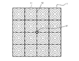
- the multi-lens Fresnel lens sheet 1 is generally rectangular, as shown in FIG.
- the center of the center line connecting the centers of the long sides of the Fresnel lens sheet is the position of the center of gravity.
- an ineffective portion where a lens is not formed may occur in a joint area of each lens or a joint portion of a mold of each lens. It is preferable to provide a lens sheet fixing portion in such an ineffective portion.
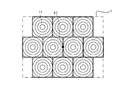
- an odd-numbered and odd-numbered multi-lens Fresnel lens sheet for example, a three-row three-stage multi-lens Fresnel lens sheet as shown in FIG. End up.
- the lens sheet fixing portion 511 is provided at the boundary portion 12 of each side of the two unit lenses, and the lens sheet fixing portion is provided at the boundary portions 12 of the four corners of the four unit lenses.
- Example 2 with 512 is shown simultaneously.
- the lens sheet fixing member 5 is provided with a lens sheet fixing member 5 other than the substantially pyramid condensing region having the Fresnel lens 11 as the base and the solar cell 3 as the apex. preferable. If the lens sheet fixing member 5 has a beam structure disposed below the multi-lens Fresnel lens sheet 1 on the condition that the lens sheet fixing member 5 is fixed by the lens sheet fixing portion 51 as shown in FIG. This is preferable in that deflection can be prevented.
- the multi-lens Fresnel lens sheet is divided into a plurality of pieces, and the present invention is applied to each Fresnel lens sheet.
- the vicinity of each gravity center position is fixed for two multi-lens Fresnel lens sheets 1 in a 6-stage, 12-row arrangement, or 6-row, 6-row.
- These four multi-lens Fresnel lens sheets may be fixed in the vicinity of their center of gravity.
- Each solar cell 3 may include a secondary condenser for compensating for the deviation of the condenser position.
- a second fixing portion 52 that does not hinder the expansion and contraction of the sheet may be provided.
- the second fixing portion 52 does not hinder the expansion and contraction of the sheet on a line extending and contracting around the lens sheet fixing portion 51 (radiating direction around the lens sheet fixing portion 51).
- a structure that prevents rotation with the lens sheet fixing portion 51 as a rotation axis is preferable.
- the second fixing portion is in the vicinity of the end portion of the entire multi-lens Fresnel sheet. This is because rotation with the lens sheet fixing portion 51 as the rotation axis can be prevented more effectively.
- the second fixing portion is a cutout of an end portion of the entire multi-lens Fresnel sheet. This is because the frame member that fixes the multi-lens Fresnel sheet can cover the cutout portion to prevent the entry of dust and moisture from the cutout portion.
- the outer shape of the multi-lens Fresnel lens sheet is not limited to a rectangle as shown in FIG. However, for example, a rectangle surrounding the entire multi-lens Fresnel lens sheet indicated by a thin line in FIG. 14 can be regarded as an outer shape in the present invention.
- the acrylic resin multi-lens Fresnel lens sheet was fixed to the aluminum frame with the structures of the examples and comparative examples, the amount by which the Fresnel lens sheet was displaced from the frame due to changes in temperature and humidity was calculated.
- the location to be calculated is the center position of the unit lens and indicates the distance change amount from the fixed point.
- the linear expansion coefficient of the acrylic resin is 6.6 ⁇ 10 ⁇ 5 (1 / ° C.)
- the linear expansion coefficient of aluminum is 2.35 ⁇ 10 ⁇ 5 (1 / ° C.)
- the hygroscopic expansion coefficient of the acrylic resin is 0.00.
- the unit lens in the upper left corner is called a unit lens 1
- the unit lenses 2 and 3 are sequentially called in the upper right direction
- the unit lens in the lower right corner is called a unit lens 18.
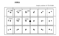
- Example 1> 9 is a case where a multi-lens Fresnel lens sheet having three vertical rows and six horizontal rows as shown in FIG. 9 is fixed at the center of the sheet, and is 65 ° C. ⁇ 85 from an environment of 25 ° C. ⁇ 0% RH.
- FIG. 10A shows the calculation result when the environment changes to% RH.
- Sheet outer shape 715 mm x 1350 mm rectangle
- FIG. 13B shows the same calculation result as in Example 1 except that the environment changed from 25 ° C. ⁇ 0% RH to 25 ° C. ⁇ 85% RH.
- Example 3 The conditions listed below and a multi-lens Fresnel lens sheet having three vertical rows and two horizontal rows as shown in FIG. 13A are used, each of which is fixed at the center of the sheet and arranged without gaps at 25 ° C.
- FIG. 13A shows the calculation result when the environment is changed from the environment of x0% RH to the environment of 25 ° C. ⁇ 85% RH.
- Sheet outer shape 715 mm x 450 mm rectangle
- Unit Fresnel lens dimensions 225 mm x 225 mm square
- Space between unit Fresnel lenses 20 mm long, 0 mm wide
- Example 4 A multi-lens Fresnel lens sheet having the following three rows and six rows was produced by injection molding using a metal mold.
- Resin Kuraray Co., Ltd. acrylic resin “Parapet (registered trademark)” Sheet outer shape: 715 mm x 1350 mm rectangle
- Unit Fresnel lens dimensions 225 mm x 225 mm square Gap between unit Fresnel lenses: 20 mm long, 0 mm wide
- Material of frame and solar cell substrate Aluminum
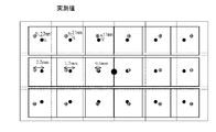
- Example 5 As in Example 1, the sheet was fixed at the center and immediately after being left for 10 days in an environment of 25 ° C. ⁇ 0% RH and immediately after being left for 10 days in an environment of 65 ° C. ⁇ 85% RH. The sheet surface positions of the Fresnel lens and the corresponding solar cells were measured, and the changes are summarized in FIG. 10B. It can be seen that the result of Example 5 is in good agreement with the result of Example 1.
- FIG. 11 shows the result of calculation for the same case as in Example 1 except that the multi-lens Fresnel lens sheet is fixed at the center of the long side of the sheet as shown in FIG.
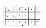
- FIG. 12 shows the result of calculation for the same case as in Calculation Example 1 except that the multi-lens Fresnel lens sheet is fixed at the lower right end of the sheet as shown in FIG.
- the numerical values for the unit lenses 4 and 5 are omitted.
- the Fresnel lens sheet and the substrate on which the solar cell is arranged have different expansion and contraction behavior due to temperature and humidity changes, the light condensing position deviates from the solar cell. Can be suppressed to a minimum, and a decrease in power generation efficiency can be prevented.
Landscapes
- Photovoltaic Devices (AREA)
Abstract
Description
図2は光発電装置の一例をフレネルレンズシートの断面方向から見た概略図であり、複数のソーラセル3が配置された基板2(以下、ソーラセル基板と称することがある)と、ソーラセル3の入光側に多眼フレネルレンズシート1を備えている。フレネルレンズの集光位置に各ソーラセル3が配置されるよう、枠4で支持されている。ここで、フレネルレンズシート1と枠4とを強固に固定すると、温度や湿度変化による伸縮差で枠やシートが破損する恐れがある。そこでシートは面方向に自在に動けるよう保持されることが望ましい。またソーラセルは放熱などのために金属性基板上に設けられることが多い。
さらに、上記の固定方法では、シートのどの部位が前記中心点として膨張するかは予想が困難であるため、前記の「ずれ」を見越して設計することは困難である。なお多眼フレネルレンズシートが長方形である場合、前記中心点が四隅近傍となった時に、対向する四隅近傍にある単位レンズの集光位置がソーラセルから最も大きくずれる。
さらに、この場合、前記第2の固定部が前記多眼フレネルレンズシート全体の端部近傍にあっても良い。
本実施形態の光発電装置の多眼フレネルレンズシート1が、温度や湿度変化によってソーラセル3が配置された基板2に対し相対的に縮んだ状態を図5Aに示す。図中右端および左端の各フレネルレンズ11の中心、即ち集光位置は対応するソーラセル3に対してずれが比較的小さく、発電効率の低下を抑制できる。
多眼フレネルレンズシートの成形では、各レンズのつなぎ目、あるいは各レンズの金型のつなぎ目箇所にレンズが形成されない無効部分が小面積生じることがある。このような無効部分にレンズシート固定部を設けることが好ましい。
また、レンズシート固定部材5は、図5Bに示すようにレンズシート固定部51で固定されることを要件として、多眼フレネルレンズシート1の下方に配置される梁構造とすると、シートの自重によるたわみを防ぐことができる点で好ましい。
また、多眼フレネルレンズシートと枠部材とを接着固定すると、熱膨張や吸水による膨張により反りが生じる場合がある。そこでそれぞれにまたは少なくとも一方と接着せずに固定できる封止部材を使用することで、上記問題を抑制できる。封止部材としては例えば、摩擦抵抗が少なく柔軟性のある部材が好ましい。
また、各ソーラセル3は集光位置のずれを補償するための二次集光器を備えていても良い。
シートの重心位置の近傍に設けるレンズシート固定部51とは別に、シートの伸縮を阻害しない第2の固定部52を設けても良い。第2の固定部52は、例えば図7に示すようにレンズシート固定部51を中心とした伸縮方向(レンズシート固定部51を中心とした放射方向)の線上に、シートの伸縮を阻害せず、レンズシート固定部51を回転軸とした回転を防ぐ構造が好ましい。
更に前記第2の固定部が前記多眼フレネルシート全体の端部近傍にあることが好ましい。これにより、レンズシート固定部51を回転軸とした回転をより効果的に防ぐことが出来るからである。
更に、前記第2の固定部が前記多眼フレネルシート全体の端部の切り欠であることが更に好ましい。これにより、多眼フレネルシートを固定する枠部材で切り欠部を覆い切り欠部からの埃や水分の浸入を防ぐ構造とすることが出来るからである。
アクリル樹脂製多眼フレネルレンズシートをアルミニウム製枠に実施例、比較例それぞれの構造で固定した場合、温度、湿度の変化によってフレネルレンズシートが枠に対して位置がずれる量を計算で示した。計算する箇所は単位レンズの中心位置であり、固定点からの距離変化量を示す。
ここでアクリル樹脂の線膨張係数を6.6×10⁻⁵(1/℃)、アルミニウムの線膨張係数を2.35×10-5(1/℃)、アクリル樹脂の吸湿膨張率を0.3%(湿度0%→85%)、アルミニウムの吸湿膨張率を0%(湿度0%→85%)として計算した。
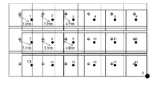
なお、固定点に対し対称位置にある単位レンズについては記載を省略する。また説明のため図9に示す通り、左上隅の単位レンズを単位レンズ1と呼び、上段右方向に順次単位レンズ2、3、右下隅の単位レンズを単位レンズ18と呼ぶ。
以下に列記した条件および図9に示すような縦3段、横6列の多眼フレネルレンズシートをシートの中心で固定した場合であって、25℃×0%RHの環境から65℃×85%RHの環境に変化した時の計算結果を図10Aに示す。
・シート外形:715mm×1350mmの長方形
・単位フレネルレンズ寸法:225mm×225mmの正方形
・単位フレネルレンズ間の隙間:縦20mm、横0mm
25℃×0%RHの環境から25℃×85%RHの環境に変化した以外は、実施例1と同様の計算結果を図13Bに示す。
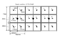
以下に列記した条件および図13Aに示すような縦3段、横2列の多眼フレネルレンズシートを用い、それぞれをシートの中心で固定し、3枚隙間無く並べた場合であって、25℃×0%RHの環境から25℃×85%RHの環境に変化した時の計算結果を図13Aに合せて示す。
・シート外形:715mm×450mmの長方形
・単位フレネルレンズ寸法:225mm×225mmの正方形
・単位フレネルレンズ間の隙間:縦20mm、横0mm
金属金型を用いた射出成形によって以下のような縦3列、横6段の多眼フレネルレンズシートを作製した。
・樹脂:株式会社クラレ製アクリル樹脂「パラペット(登録商標)」
・シート外形:715mm×1350mmの長方形
・単位フレネルレンズ寸法:225mm×225mmの正方形
・単位フレネルレンズ間の隙間:縦20mm、横0mm
・フレームおよびソーラセル基板の材質:アルミニウム
実施例1と同様にシートをその中心部で固定して、25℃×0%RHの環境下で10日間放置した直後、及び65℃×85%RHの環境下で10日間放置した直後について単位フレネルレンズと対応する各ソーラセルとのシート面方向の位置をそれぞれ測定し、その変化を図10Bにまとめた。
この実施例5の結果は実施例1の結果とよく一致していることが分かる。
図11に示すように多眼フレネルレンズシートをシート長辺の中心で固定した以外は実施例1と同様の場合について計算した結果を図11に合せて示す。
図12示すように多眼フレネルレンズシートをシート右下端部で固定した以外は計算例1と同様の場合について計算した結果を図12に合せて示す。なお、単位レンズ4,5などについての数値は省略する。
本出願は、2010年10月27日に日本国特許庁に出願された特願2010-241226号に基づいて優先権を主張し、その全ての開示は完全に本明細書で参照により組み込まれる。
Claims (4)
- 一体に成形された多眼フレネルレンズシートと、個々のフレネルレンズの集光位置近傍にソーラセルが配置された基板とを備えた光発電装置であって、前記多眼フレネルレンズシートはその重心位置の近傍に位置するレンズシート固定部で前記基板に対して固定されていることを特徴とする光発電装置。
- 請求項1に記載の光発電装置において、
前記多眼フレネルレンズシートが、その重心位置の近傍、かつ、個々のフレネルレンズの境界部に位置するレンズシート固定部で前記基板に対して固定されていることを特徴とする。 - 請求項1または2に記載の光発電装置において、
前記多眼フレネルシートが、前記レンズシート固定部の他に第2の固定部を有しており、前記第2の固定部において、多眼フレネルレンズシートは前記レンズシート固定部と前記第2の固定部とを結ぶ方向にのみ変位可能であることを特徴とする。 - 請求項3に記載の光発電装置において、
前記第2の固定部が前記多眼フレネルレンズシート全体の端部近傍にあることを特徴とする。
Priority Applications (5)
| Application Number | Priority Date | Filing Date | Title |
|---|---|---|---|
| JP2012540827A JP6090694B2 (ja) | 2010-10-27 | 2011-10-21 | 光発電装置 |
| KR1020137012948A KR101460984B1 (ko) | 2010-10-27 | 2011-10-21 | 광발전 장치 |
| US13/882,046 US9343605B2 (en) | 2010-10-27 | 2011-10-21 | Photovoltaic equipment |
| EP11836167.4A EP2634819A4 (en) | 2010-10-27 | 2011-10-21 | PHOTOVOLTAIC DEVICE |
| CN201180063035.4A CN103262260B (zh) | 2010-10-27 | 2011-10-21 | 光发电装置 |
Applications Claiming Priority (2)
| Application Number | Priority Date | Filing Date | Title |
|---|---|---|---|
| JP2010-241226 | 2010-10-21 | ||
| JP2010241226 | 2010-10-27 |
Publications (1)
| Publication Number | Publication Date |
|---|---|
| WO2012057033A1 true WO2012057033A1 (ja) | 2012-05-03 |
Family
ID=45993743
Family Applications (1)
| Application Number | Title | Priority Date | Filing Date |
|---|---|---|---|
| PCT/JP2011/074324 Ceased WO2012057033A1 (ja) | 2010-10-27 | 2011-10-21 | 光発電装置 |
Country Status (7)
| Country | Link |
|---|---|
| US (1) | US9343605B2 (ja) |
| EP (1) | EP2634819A4 (ja) |
| JP (1) | JP6090694B2 (ja) |
| KR (1) | KR101460984B1 (ja) |
| CN (1) | CN103262260B (ja) |
| TW (1) | TWI524547B (ja) |
| WO (1) | WO2012057033A1 (ja) |
Cited By (1)
| Publication number | Priority date | Publication date | Assignee | Title |
|---|---|---|---|---|
| JP2023120951A (ja) * | 2022-02-18 | 2023-08-30 | あいホールディングス株式会社 | 集光レンズモジュール及び太陽光発電パネル |
Families Citing this family (1)
| Publication number | Priority date | Publication date | Assignee | Title |
|---|---|---|---|---|
| CN106936381A (zh) * | 2015-12-30 | 2017-07-07 | 中国科学院西安光学精密机械研究所 | 一种聚光太阳能模组安装方法 |
Citations (5)
| Publication number | Priority date | Publication date | Assignee | Title |
|---|---|---|---|---|
| US5125983A (en) | 1991-04-22 | 1992-06-30 | Electric Power Research Institute, Inc. | Generating electric power from solar radiation |
| JPH1126800A (ja) | 1997-07-07 | 1999-01-29 | Toyota Central Res & Dev Lab Inc | 集光式太陽電池装置 |
| JP2005317588A (ja) * | 2004-04-27 | 2005-11-10 | Kyocera Corp | 太陽光発電装置 |
| WO2009090843A1 (ja) * | 2008-01-17 | 2009-07-23 | Sharp Kabushiki Kaisha | 集光型太陽光発電ユニットおよび集光型太陽光発電ユニット製造方法 |
| JP2010241226A (ja) | 2009-04-03 | 2010-10-28 | Sumitomo Rubber Ind Ltd | 突起駆動型ゴムクローラ |
Family Cites Families (12)
| Publication number | Priority date | Publication date | Assignee | Title |
|---|---|---|---|---|
| US4511755A (en) * | 1982-05-17 | 1985-04-16 | Kei Mori | Solar ray collection apparatus |
| JPS58199303A (ja) * | 1982-05-17 | 1983-11-19 | Takashi Mori | 太陽光収集装置 |
| US5118361A (en) | 1990-05-21 | 1992-06-02 | The Boeing Company | Terrestrial concentrator solar cell module |
| ITRM20040646A1 (it) * | 2004-12-29 | 2005-03-29 | Enea Ente Nuove Tec | Elemento strutturale integrato per modulo fotovoltaico a concentrazione. |
| WO2006132265A1 (ja) | 2005-06-07 | 2006-12-14 | Sharp Kabushiki Kaisha | 集光型太陽光発電ユニットおよび集光型太陽光発電装置、ならびに集光レンズ、集光レンズ構造体、および集光レンズ構造体の製造方法 |
| US7658071B1 (en) | 2005-12-12 | 2010-02-09 | Mcdermott Patrick P | Solfire solar concentrator and pointer structure |
| DE102006007472B4 (de) * | 2006-02-17 | 2018-03-22 | Fraunhofer-Gesellschaft zur Förderung der angewandten Forschung e.V. | Photovoltaisches Konzentratormodul mit Multifunktionsrahmen |
| WO2009038307A2 (en) * | 2007-09-20 | 2009-03-26 | Dae Ho Seo | Generating apparatus using a high concentrator photovoltaic module |
| KR100981685B1 (ko) * | 2007-10-19 | 2010-09-10 | 재단법인서울대학교산학협력재단 | 마이크로렌즈를 이용한 태양전지 장치 및 그 제조 방법 |
| US20090183762A1 (en) * | 2008-01-18 | 2009-07-23 | Energy Innovations Inc. | Low-voltage tracking solar concentrator |
| AU2009237000B2 (en) * | 2008-04-17 | 2012-05-17 | Sharp Kabushiki Kaisha | Tracking drive type solar power generation apparatus |
| KR100979819B1 (ko) | 2008-06-03 | 2010-09-06 | 주식회사 이에스파워 | 일체형 프레넬 렌즈의 결합체 및 이를 이용한 태양광발전모듈 |
-
2011
- 2011-10-21 KR KR1020137012948A patent/KR101460984B1/ko not_active Expired - Fee Related
- 2011-10-21 CN CN201180063035.4A patent/CN103262260B/zh not_active Expired - Fee Related
- 2011-10-21 US US13/882,046 patent/US9343605B2/en not_active Expired - Fee Related
- 2011-10-21 WO PCT/JP2011/074324 patent/WO2012057033A1/ja not_active Ceased
- 2011-10-21 JP JP2012540827A patent/JP6090694B2/ja not_active Expired - Fee Related
- 2011-10-21 EP EP11836167.4A patent/EP2634819A4/en not_active Withdrawn
- 2011-10-26 TW TW100138854A patent/TWI524547B/zh not_active IP Right Cessation
Patent Citations (5)
| Publication number | Priority date | Publication date | Assignee | Title |
|---|---|---|---|---|
| US5125983A (en) | 1991-04-22 | 1992-06-30 | Electric Power Research Institute, Inc. | Generating electric power from solar radiation |
| JPH1126800A (ja) | 1997-07-07 | 1999-01-29 | Toyota Central Res & Dev Lab Inc | 集光式太陽電池装置 |
| JP2005317588A (ja) * | 2004-04-27 | 2005-11-10 | Kyocera Corp | 太陽光発電装置 |
| WO2009090843A1 (ja) * | 2008-01-17 | 2009-07-23 | Sharp Kabushiki Kaisha | 集光型太陽光発電ユニットおよび集光型太陽光発電ユニット製造方法 |
| JP2010241226A (ja) | 2009-04-03 | 2010-10-28 | Sumitomo Rubber Ind Ltd | 突起駆動型ゴムクローラ |
Non-Patent Citations (1)
| Title |
|---|
| See also references of EP2634819A4 |
Cited By (2)
| Publication number | Priority date | Publication date | Assignee | Title |
|---|---|---|---|---|
| JP2023120951A (ja) * | 2022-02-18 | 2023-08-30 | あいホールディングス株式会社 | 集光レンズモジュール及び太陽光発電パネル |
| JP7672706B2 (ja) | 2022-02-18 | 2025-05-08 | あいホールディングス株式会社 | 集光レンズモジュール及び太陽光発電パネル |
Also Published As
| Publication number | Publication date |
|---|---|
| JPWO2012057033A1 (ja) | 2014-05-12 |
| KR20130087024A (ko) | 2013-08-05 |
| JP6090694B2 (ja) | 2017-03-08 |
| TW201227992A (en) | 2012-07-01 |
| EP2634819A4 (en) | 2015-03-18 |
| CN103262260A (zh) | 2013-08-21 |
| EP2634819A1 (en) | 2013-09-04 |
| KR101460984B1 (ko) | 2014-11-14 |
| US9343605B2 (en) | 2016-05-17 |
| CN103262260B (zh) | 2015-11-25 |
| TWI524547B (zh) | 2016-03-01 |
| US20130291928A1 (en) | 2013-11-07 |
Similar Documents
| Publication | Publication Date | Title |
|---|---|---|
| JP6525005B2 (ja) | 太陽光発電モジュールおよび太陽光発電パネル | |
| KR102468411B1 (ko) | 광 흡수 또는 광 방출을 위한 광기계 시스템 및 상응하는 방법 | |
| ES2584335T3 (es) | Módulo para aplicaciones solares fotovoltaicas de alta concentración | |
| CN102812556A (zh) | 太阳能模块结构 | |
| JP6090694B2 (ja) | 光発電装置 | |
| KR101207852B1 (ko) | 평판형 고집광 태양전지 모듈 및 이를 이용한 태양광 트랙커 | |
| CN102748674A (zh) | 背光模块以及液晶显示器 | |
| JP2013214650A (ja) | 太陽電池モジュール | |
| JP2014038881A (ja) | 集光型太陽光発電モジュール及び集光型太陽光発電パネル | |
| WO2014045692A1 (ja) | 太陽電池封止材シート、および、太陽電池モジュール | |
| US20210367554A1 (en) | Fresnel lens for concentrator photovoltaic apparatus, concentrator photovoltaic system, and method of manufacturing fresnel lens for concentrator photovoltaic apparatus | |
| US11831272B2 (en) | Kirigami-based multi-axis tracking devices and systems | |
| US11894804B2 (en) | Photovoltaic module, photovoltaic panel, and production method for photovoltaic module | |
| JP2014220268A (ja) | 集光型太陽光発電装置および集光レンズ部材 | |
| WO2019030988A1 (ja) | 集光型太陽光発電モジュール、集光型太陽光発電パネル、及び集光型太陽光発電装置 | |
| JP5197665B2 (ja) | 光電変換装置 | |
| JPWO2019030989A1 (ja) | 集光型太陽光発電モジュール、集光型太陽光発電パネル、集光型太陽光発電装置、及び集光型太陽光発電モジュールの製造方法 | |
| JP2011103426A (ja) | 太陽電池モジュール | |
| WO2019159554A1 (ja) | 集光型太陽光発電モジュール及び集光型太陽光発電装置 | |
| JP2012054515A (ja) | 太陽電池モジュールの製造方法 | |
| TW201824734A (zh) | 聚焦型太陽能發電模組、聚焦型太陽能發電面板、及聚焦型太陽能發電裝置 | |
| KR101095842B1 (ko) | 광전변환기 | |
| WO2019004325A1 (ja) | レンズアレイ及びレンズアレイの製造方法 | |
| TWI420682B (zh) | Photoelectric conversion device | |
| CN103681929A (zh) | 聚光光伏发电模组结构 |
Legal Events
| Date | Code | Title | Description |
|---|---|---|---|
| 121 | Ep: the epo has been informed by wipo that ep was designated in this application |
Ref document number: 11836167 Country of ref document: EP Kind code of ref document: A1 |
|
| ENP | Entry into the national phase |
Ref document number: 2012540827 Country of ref document: JP Kind code of ref document: A |
|
| NENP | Non-entry into the national phase |
Ref country code: DE |
|
| WWE | Wipo information: entry into national phase |
Ref document number: 2011836167 Country of ref document: EP |
|
| ENP | Entry into the national phase |
Ref document number: 20137012948 Country of ref document: KR Kind code of ref document: A |
|
| WWE | Wipo information: entry into national phase |
Ref document number: 13882046 Country of ref document: US |