WO2012057065A1 - ターボ過給システム - Google Patents
ターボ過給システム Download PDFInfo
- Publication number
- WO2012057065A1 WO2012057065A1 PCT/JP2011/074411 JP2011074411W WO2012057065A1 WO 2012057065 A1 WO2012057065 A1 WO 2012057065A1 JP 2011074411 W JP2011074411 W JP 2011074411W WO 2012057065 A1 WO2012057065 A1 WO 2012057065A1
- Authority
- WO
- WIPO (PCT)
- Prior art keywords
- pressure
- turbocharger
- compressor
- electric motor
- engine
- Prior art date
- Legal status (The legal status is an assumption and is not a legal conclusion. Google has not performed a legal analysis and makes no representation as to the accuracy of the status listed.)
- Ceased
Links
Images


Classifications
-
- F—MECHANICAL ENGINEERING; LIGHTING; HEATING; WEAPONS; BLASTING
- F02—COMBUSTION ENGINES; HOT-GAS OR COMBUSTION-PRODUCT ENGINE PLANTS
- F02M—SUPPLYING COMBUSTION ENGINES IN GENERAL WITH COMBUSTIBLE MIXTURES OR CONSTITUENTS THEREOF
- F02M26/00—Engine-pertinent apparatus for adding exhaust gases to combustion-air, main fuel or fuel-air mixture, e.g. by exhaust gas recirculation [EGR] systems
- F02M26/02—EGR systems specially adapted for supercharged engines
- F02M26/03—EGR systems specially adapted for supercharged engines with a single mechanically or electrically driven intake charge compressor
-
- F—MECHANICAL ENGINEERING; LIGHTING; HEATING; WEAPONS; BLASTING
- F02—COMBUSTION ENGINES; HOT-GAS OR COMBUSTION-PRODUCT ENGINE PLANTS
- F02B—INTERNAL-COMBUSTION PISTON ENGINES; COMBUSTION ENGINES IN GENERAL
- F02B37/00—Engines characterised by provision of pumps driven at least for part of the time by exhaust
- F02B37/004—Engines characterised by provision of pumps driven at least for part of the time by exhaust with exhaust drives arranged in series
-
- F—MECHANICAL ENGINEERING; LIGHTING; HEATING; WEAPONS; BLASTING
- F02—COMBUSTION ENGINES; HOT-GAS OR COMBUSTION-PRODUCT ENGINE PLANTS
- F02B—INTERNAL-COMBUSTION PISTON ENGINES; COMBUSTION ENGINES IN GENERAL
- F02B37/00—Engines characterised by provision of pumps driven at least for part of the time by exhaust
- F02B37/013—Engines characterised by provision of pumps driven at least for part of the time by exhaust with exhaust-driven pumps arranged in series
-
- F—MECHANICAL ENGINEERING; LIGHTING; HEATING; WEAPONS; BLASTING
- F02—COMBUSTION ENGINES; HOT-GAS OR COMBUSTION-PRODUCT ENGINE PLANTS
- F02B—INTERNAL-COMBUSTION PISTON ENGINES; COMBUSTION ENGINES IN GENERAL
- F02B37/00—Engines characterised by provision of pumps driven at least for part of the time by exhaust
- F02B37/04—Engines with exhaust drive and other drive of pumps, e.g. with exhaust-driven pump and mechanically-driven second pump
- F02B37/10—Engines with exhaust drive and other drive of pumps, e.g. with exhaust-driven pump and mechanically-driven second pump at least one pump being alternatively or simultaneously driven by exhaust and other drive, e.g. by pressurised fluid from a reservoir or an engine-driven pump
-
- F—MECHANICAL ENGINEERING; LIGHTING; HEATING; WEAPONS; BLASTING
- F02—COMBUSTION ENGINES; HOT-GAS OR COMBUSTION-PRODUCT ENGINE PLANTS
- F02B—INTERNAL-COMBUSTION PISTON ENGINES; COMBUSTION ENGINES IN GENERAL
- F02B39/00—Component parts, details, or accessories relating to, driven charging or scavenging pumps, not provided for in groups F02B33/00 - F02B37/00
- F02B39/02—Drives of pumps; Varying pump drive gear ratio
- F02B39/08—Non-mechanical drives, e.g. fluid drives having variable gear ratio
- F02B39/10—Non-mechanical drives, e.g. fluid drives having variable gear ratio electric
-
- F—MECHANICAL ENGINEERING; LIGHTING; HEATING; WEAPONS; BLASTING
- F02—COMBUSTION ENGINES; HOT-GAS OR COMBUSTION-PRODUCT ENGINE PLANTS
- F02D—CONTROLLING COMBUSTION ENGINES
- F02D21/00—Controlling engines characterised by their being supplied with non-airborne oxygen or other non-fuel gas
- F02D21/06—Controlling engines characterised by their being supplied with non-airborne oxygen or other non-fuel gas peculiar to engines having other non-fuel gas added to combustion air
- F02D21/08—Controlling engines characterised by their being supplied with non-airborne oxygen or other non-fuel gas peculiar to engines having other non-fuel gas added to combustion air the other gas being the exhaust gas of engine
-
- F—MECHANICAL ENGINEERING; LIGHTING; HEATING; WEAPONS; BLASTING
- F02—COMBUSTION ENGINES; HOT-GAS OR COMBUSTION-PRODUCT ENGINE PLANTS
- F02D—CONTROLLING COMBUSTION ENGINES
- F02D23/00—Controlling engines characterised by their being supercharged
-
- Y—GENERAL TAGGING OF NEW TECHNOLOGICAL DEVELOPMENTS; GENERAL TAGGING OF CROSS-SECTIONAL TECHNOLOGIES SPANNING OVER SEVERAL SECTIONS OF THE IPC; TECHNICAL SUBJECTS COVERED BY FORMER USPC CROSS-REFERENCE ART COLLECTIONS [XRACs] AND DIGESTS
- Y02—TECHNOLOGIES OR APPLICATIONS FOR MITIGATION OR ADAPTATION AGAINST CLIMATE CHANGE
- Y02T—CLIMATE CHANGE MITIGATION TECHNOLOGIES RELATED TO TRANSPORTATION
- Y02T10/00—Road transport of goods or passengers
- Y02T10/10—Internal combustion engine [ICE] based vehicles
- Y02T10/12—Improving ICE efficiencies
Definitions
- the present invention relates to a turbocharging system in which a high-pressure stage turbocharger and a low-pressure stage turbocharger are connected in series.
- the two-stage turbo includes a parallel two-stage turbo in which two turbochargers are connected in parallel and a series two-stage turbo in which two turbochargers are connected in series (for example, see Patent Document 1).
- EGR exhaust Gas Recirculation
- an EGR pipe that connects the intake manifold (or intake passage) and the exhaust manifold (or exhaust passage) of the engine is provided, and the opening of the EGR valve provided in the EGR pipe is adjusted so that The EGR amount (or EGR rate) that is the amount of exhaust gas to be recirculated is controlled.
- EGR control a part of the exhaust gas is recirculated to the intake side to reduce the oxygen concentration of the gas sucked into the engine, thereby reducing the maximum combustion temperature and the time for exposure to the maximum combustion temperature, thereby reducing NOx generation. Suppressed. However, if the oxygen concentration is lowered, the absolute amount of oxygen necessary for combustion in the engine will be insufficient. Therefore, the boost pressure is maintained high to increase the intake air flow rate, and the oxygen supplied to the engine is reduced. Control is required to increase the EGR amount and lower the oxygen concentration while ensuring the absolute amount.
- the EGR amount cannot be increased in the low load region or in the transient operation, and as a result, the amount of NOx discharged from the engine has increased. Since a large amount of NOx discharged from the engine cannot be released into the atmosphere as it is, it has been conventionally practiced to purify NOx using a NOx catalyst.
- the NOx catalyst is very expensive, it is desirable to simplify or eliminate the NOx catalyst. If a sufficient amount of EGR can be secured in any operating state, the amount of NOx discharged from the engine becomes very small, and the NOx catalyst can be simplified or eliminated.
- an object of the present invention is to provide a turbocharger system that solves the above-described problems, can secure a sufficient EGR amount in any operating state, and can reduce NOx emission from the engine.
- the present invention was devised to achieve the above object, and an EGR control means for recirculating a part of exhaust gas discharged from the engine to the intake side, and a turbine that is disposed in the exhaust passage and driven by exhaust gas
- a turbocharger for an engine comprising: a turbocharger disposed in an intake passage and driven by a rotational torque of the turbine; wherein the turbocharger assists the driving force of the compressor
- the EGR control means includes an electric assist turbocharger equipped with an electric motor, and controls the amount of exhaust gas recirculated to the intake side so as to suppress NOx generation regardless of the amount of oxygen necessary for engine combustion. The amount of oxygen necessary for engine combustion is insufficient due to the control of the EGR control means.
- the turbocharger includes a high-pressure stage turbine disposed in the exhaust passage and driven by exhaust gas, and a high-pressure stage compressor disposed in the intake passage and driven by rotational torque of the high-pressure stage turbine.
- a low-pressure turbine that is disposed in the exhaust passage downstream of the high-pressure turbine and is driven by exhaust gas; and the low-pressure turbine disposed in the intake passage upstream of the high-pressure compressor.
- a low-pressure stage turbocharger having a low-pressure stage compressor driven by the rotational torque of the compressor.
- the electric motor control unit ensures the power performance of the vehicle even when the boost pressure, which is the outlet pressure of the high-pressure compressor, makes the amount of exhaust gas recirculated to the intake side by EGR control the most capable of suppressing the generation of NOx.
- the electric motor may be driven when the target boost pressure is smaller than a target boost pressure.
- a boost pressure sensor that measures the boost pressure that is the outlet pressure of the high-pressure compressor, and a target boost pressure that takes into account the amount of exhaust gas recirculated to the intake side by the EGR control is set for each engine speed and engine torque.
- a high-pressure stage compressor characteristic map that is a relationship between the pressure ratio of the boost pressure, and the electric motor control unit obtains a target pressure ratio from a ratio between the inlet pressure measured by the inlet pressure sensor and the target boost pressure.
- the high pressure by the target pressure ratio and the intake air flow rate measured by the intake air flow rate measuring means Obtains a target turbo rotational speed by referring to the compressor characteristic map, in accordance with the deviation of the target turbo rotation speed determined the current turbo rotation speed may be controlled driving amount by the electric motor.
- turbocharging system that can secure a sufficient amount of EGR in any operating state and can reduce the amount of NOx discharged from the engine.
- FIG. 1 is a schematic configuration diagram of an engine system using a turbocharger system according to an embodiment of the present invention. It is a figure which shows an example of the target boost pressure map used with the turbo supercharging system of FIG. It is a figure which shows an example of the high pressure stage compressor characteristic map used with the turbo supercharging system of FIG.
- FIG. 1 is a schematic configuration diagram of an engine system using a turbocharger system according to the present embodiment.
- the turbocharger system 1 is composed of a series two-stage turbo in which a small (small capacity) high-pressure stage turbocharger 2 and a large (large capacity) low-pressure stage turbocharger 3 are connected in series. Is done.
- the high-pressure stage turbocharger 2 is disposed in the exhaust passage 4 of the engine E and driven by exhaust gas, and the high-pressure stage compressor 2b is disposed in the intake passage 5 and driven by rotational torque of the high-pressure stage turbine 2a. And have.
- the low-pressure stage turbocharger 3 is disposed in the exhaust passage 4 downstream of the high-pressure stage turbine 2a and is driven by exhaust, and is disposed in the intake passage 5 upstream of the high-pressure stage compressor 2b. And a low-pressure compressor 3b driven by the rotational torque of the low-pressure turbine 3a.
- the uppermost stream of the exhaust passage 4 is connected to an exhaust manifold 6 of the engine E, and a high-pressure turbine 2a and a low-pressure turbine 3a are sequentially provided in the exhaust passage 4 on the downstream side.
- An air filter 7 is provided in the uppermost stream of the intake passage 5, and a low-pressure compressor 3 b, a high-pressure compressor 2 b, and an intercooler 8 are sequentially provided in the intake passage 5 on the downstream side thereof.
- the exhaust passage 4 is provided with a high-pressure turbine bypass line 10 that bypasses the high-pressure turbine 2a and a low-pressure turbine bypass line 11 that bypasses the low-pressure turbine 3a.
- the turbine bypass valve 10a and the low-pressure turbine bypass line 11 are provided with a low-pressure turbine bypass valve 11a.
- the intake passage 5 is provided with a high-pressure compressor bypass line 12 so as to bypass the high-pressure compressor 2b, and the high-pressure compressor bypass line 12 is provided with a high-pressure compressor bypass valve 12a.
- the turbocharging system 1 measures a boost pressure sensor 13 that measures a boost pressure that is an outlet pressure of the high-pressure stage compressor 2b, an inlet pressure sensor 14 that measures an inlet pressure of the high-pressure stage compressor 2b, and measures an intake air flow rate.
- an unillustrated intake air flow rate measuring means for example, MAF sensor.
- the boost pressure sensor 13 is provided in the intake manifold 9, and the inlet pressure sensor 14 is provided in the intake passage 5 on the upstream side of the low-pressure compressor 3b. Note that, in a region where the low pressure turbocharger 3 is not used, such as a region where the engine speed is extremely low, the measured value of the inlet pressure sensor 14 is substantially equal to the inlet pressure of the high pressure compressor 2b.
- the turbocharger system 1 includes a turbo switching control unit 21 that switches between turbochargers 2 and 3 to be used according to engine speed (engine speed) and engine torque (load).
- the turbo switching control unit 21 is incorporated as a program in an ECU (Electronic Control Unit) 20.
- the turbo switching control unit 21 closes the high pressure turbine bypass valve 10a and the high pressure compressor bypass valve 12a and drives the high pressure turbocharger 2 in a region where the engine speed is low and the exhaust energy is small. At this time, the exhaust gas is also supplied to the low-pressure stage turbine 3a, and the low-pressure stage turbocharger 3 is driven by the remaining exhaust energy. However, in the region where the engine speed is low and the exhaust energy is small, the low-pressure stage turbine 3a The work cannot be performed, and only the high-pressure stage turbocharger 2 is operated.
- the turbo switching control unit 21 is configured to control the high-pressure turbine bypass valve 10a in a region where the engine speed is high and the exhaust energy is large, in order to suppress deterioration of fuel consumption due to excessive rotation of the high-pressure turbocharger 2 and abnormal increase in exhaust pressure.
- the high pressure compressor bypass valve 12a is opened, the low pressure turbine bypass valve 11a is closed, and only the low pressure turbocharger 3 is driven.
- the low-pressure stage turbine bypass valve 11a is opened to reduce fuel consumption due to excessive rotation of the low-pressure stage turbocharger 3 and abnormal increase in exhaust pressure. To be suppressed.
- turbo switching control unit 21 closes the low-pressure stage turbine bypass valve 11a and the high-pressure stage compressor bypass valve 12a and adjusts the opening degree of the high-pressure stage turbine bypass valve 10a in a region between the low engine speed region and the high engine region.
- both the high-pressure stage turbocharger 2 and the low-pressure stage turbocharger 3 are driven at a rate corresponding to the opening degree of the high-pressure stage turbine bypass valve 10a.
- the turbocharger system 1 is provided with EGR control means for returning a part of the exhaust gas discharged from the engine to the intake side.
- the EGR control means is an EGR pipe 15 that connects the exhaust passage 4 between the exhaust manifold 6 and the high-pressure turbine 2a and the intake manifold 9, and the amount of exhaust gas that is provided in the EGR pipe 15 and recirculates to the intake side.
- the EGR valve 16 for adjusting the EGR amount (or EGR rate) and the ECU 20 are equipped with an optimal target EGR amount (which most suppresses the generation of NOx) according to engine parameters such as engine speed and fuel injection amount.
- an EGR control unit 25 that controls the opening degree of the EGR valve 16 so that the EGR amount becomes the target EGR amount.
- the EGR control unit 25 controls the EGR amount so as to suppress the generation of NOx regardless of the oxygen amount necessary for the combustion of the engine E.
- the turbocharging system 1 includes an electric motor 2c that assists the driving force of the high-pressure compressor 2b (assums the rotational torque of the high-pressure turbine 2a) as the high-pressure turbocharger 2.
- An electric assist turbocharger (hybrid turbo) is used.
- the electric motor 2c is integrally provided between the high-pressure turbine 2a and the high-pressure compressor 2b, more specifically, a turbo shaft that connects the turbine wheel of the high-pressure turbine 2a and the compressor wheel of the high-pressure compressor 2b.
- the electric motor 2c is composed of, for example, a DC servo motor. Since the electric motor 2c is provided integrally with the turbo shaft, the rotational speed of the electric motor 2c is equal to the rotational speed (turbo rotational speed) of the high-pressure turbocharger 2.
- the turbo supercharging system 1 is an EGR amount (target EGR amount) that can most suppress the generation of NOx.
- the boost pressure is insufficient with respect to the EGR amount (that is, when the intake air flow rate is insufficient and the absolute amount of oxygen is insufficient)
- the electric motor control unit that drives the electric motor 2c 23.
- the turbocharging system 1 includes a target boost pressure map 22 in which a target boost pressure is set in consideration of the amount of exhaust gas recirculated to the intake side by EGR control for each engine speed and engine torque.
- the unit 23 drives the electric motor when the boost pressure detected by the boost pressure sensor 13 is smaller than the target boost pressure obtained by referring to the target boost pressure map 22 with the engine speed and the engine torque.
- the turbocharger system 1 includes a high-pressure stage compressor characteristic map 24 that is a relationship between the pressure ratio of the inlet pressure and the boost pressure with respect to the intake air flow rate at each turbo rotation speed in the high-pressure stage compressor 2b, and an electric motor control unit.
- 23 obtains a target pressure ratio from the ratio between the inlet pressure measured by the inlet pressure sensor 14 and the target boost pressure, and the high pressure stage compressor characteristic map based on the target pressure ratio and the intake air flow rate measured by the intake air flow rate measuring means. 24, the target turbo speed is obtained, and the drive amount (assist amount) by the electric motor 2c is controlled according to the difference between the obtained target turbo speed and the current turbo speed.
- the target boost pressure map 22, the electric motor control unit 23, and the high pressure compressor characteristic map 24 are mounted on the ECU 20.
- the ECU 20 recognizes all engine parameters such as engine speed and fuel injection amount in order to control the engine E.
- the electric motor control unit 23 refers to the target boost pressure map 22 with the engine speed and the engine torque, and obtains the target boost pressure.
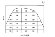
- An example of the target boost pressure map 22 used at this time is shown in FIG.
- the target boost pressure map 22 is a map in which target boost pressures (values indicated by numbers in FIG. 2) are set for each engine speed and engine torque.
- the target boost pressure is set to a value that can secure sufficient power performance even if the EGR amount is set as the target EGR amount (EGR amount that can most suppress the generation of NOx) under the conditions of each engine speed and engine torque.
- the engine torque can be obtained from engine parameters such as the fuel injection amount.
- the assist amount by the electric motor 2c is controlled so that the actual boost pressure approaches the target boost pressure.
- the electric motor 2c can easily control the rotational speed. It is also effective to control the assist amount by instructing the rotation speed of the electric motor 2c.
- the electric motor control unit 23 obtains the target pressure ratio from the ratio of the inlet pressure measured by the inlet pressure sensor 14 and the target boost pressure, and also determines the boost pressure and the inlet pressure measured by the boost pressure sensor 13.
- the current pressure ratio is obtained from the ratio of.
- the pressure ratio obtained here is the same as that of the low-pressure stage compressor 3b. This is a total value of the pressure ratio between the inlet and the outlet and the pressure ratio between the inlet and the outlet of the high-pressure compressor 2b.
- the exhaust energy is large and the actual boost pressure becomes equal to or higher than the target boost pressure. Therefore, the assist by the electric motor 2c is not actually performed (assist by the electric motor 2c). However, the fuel consumption worsens due to power consumption).
- the actual boost pressure becomes smaller than the target boost pressure only in a region where the engine speed is low.
- the inlet pressure measured by the inlet pressure sensor 14 is substantially equal to the inlet pressure of the high-pressure stage compressor 2b, and the ratio between the inlet pressure and the boost pressure is taken.
- the pressure ratio between the inlet and the outlet of the high-pressure compressor 2b can be obtained.
- the electric motor control unit 23 refers to the high-pressure stage compressor characteristic map 24 based on the target pressure ratio and the intake air flow rate measured by the intake air flow rate measuring means, obtains the target turbo speed, and determines the current pressure ratio and The current turbo speed is obtained by referring to the high-pressure compressor characteristic map 24 based on the intake air flow rate.
- An example of the high-pressure compressor characteristic map 24 used at this time is shown in FIG.
- the high-pressure stage compressor characteristic map 24 is a map showing the relationship between the inlet / outlet pressure ratio of the high-pressure stage compressor 2b and the intake air amount for each turbo speed of the high-pressure stage turbocharger 2. It shows the characteristics of the high-pressure compressor.
- the turbo speed (current turbo speed) at point A and B From the difference from the turbo rotational speed at a point (target turbo rotational speed), the necessary rotational speed increase can be obtained.
- the electric motor control unit 23 controls the electric motor 2c (for example, controls the magnitude of the voltage applied to the electric motor 2c) in accordance with the required rotation speed increase so that the turbo rotation speed becomes the target turbo rotation speed. To control.
- the high-pressure stage turbocharger 2 is configured by an electric assist turbocharger including the electric motor 2c that assists the driving force of the high-pressure stage compressor 2b.
- the EGR amount is set to an amount that can suppress the generation of NOx most, when the boost pressure is insufficient with respect to the EGR amount, the electric motor 2c is driven.
- the electric motor 2c If the electric motor 2c is driven, a sufficient boost pressure can be obtained regardless of the operating state. Therefore, the electric motor 2c can be used in a low load region where the exhaust energy is small or during a transient operation that is easily affected by the inertia of the turbo impeller. However, a sufficient boost pressure can be secured. Therefore, a sufficient amount of EGR can be ensured in any operating state, and the optimum amount of EGR can be obtained at any time (the most NOx can be suppressed), and the amount of NOx discharged from the engine E can be reduced. It becomes possible. As a result, the expensive NOx catalyst can be simplified or eliminated, and the cost can be greatly reduced.
- the electric motor 2c is driven when the boost pressure measured by the boost pressure sensor 13 is lower than the target boost pressure obtained by the target boost pressure map 22, but the electric motor 2c
- the index for driving the engine is not limited to the boost pressure.
- the pressure ratio between the inlet and the outlet of the high-pressure compressor 2b, or the excess air ratio of the exhaust or intake air, the intake air amount, etc. are used as indices.
- the electric motor 2c may be driven when it is low.
- a rotation speed sensor for detecting the turbo rotation speed of the high-pressure turbocharger 2 is provided, and the assist amount by the electric motor 2c is controlled according to the difference between the turbo rotation speed detected by the rotation speed sensor and the target turbo rotation speed. You may make it do.
- both the high-pressure turbine 2a and the high-pressure compressor 2b rotate, so that the pressure at the inlet of the high-pressure turbine 2a decreases, and the high-pressure compressor 2a The outlet pressure rises. Therefore, when the efficiency of the high-pressure stage turbocharger 2 is very high, the pressure difference between the intake passage 5 side and the exhaust passage 4 side of the EGR pipe 15 becomes small, and the EGR amount does not increase so much even if the EGR valve 16 is opened. There are cases.
- the EGR pipe 15 is provided with a reed valve (one-way valve) that allows exhaust gas to flow from the exhaust side to the intake side only in one direction, and the EGR amount is secured by utilizing pressure pulsation. Also good.
- the present invention is applied to a series two-stage turbo has been described as an example.
- the scope of the present invention is not limited to a series two-stage turbo, for example, a turbocharger having only one stage.
- the present invention can also be applied to a turbocharger system equipped with.
Landscapes
- Engineering & Computer Science (AREA)
- Chemical & Material Sciences (AREA)
- Combustion & Propulsion (AREA)
- Mechanical Engineering (AREA)
- General Engineering & Computer Science (AREA)
- Supercharger (AREA)
- Output Control And Ontrol Of Special Type Engine (AREA)
Abstract
どのような運転状態でも十分なEGR量が確保でき、エンジンからのNOxの排出量を低減可能なターボ過給システムを提供する。エンジンから排出される排気ガスの一部を吸気側に還流させるEGR制御手段と、ターボチャージャと、を備えたエンジンのターボ過給システムにおいて、ターボチャージャは、コンプレッサ(2b)の駆動力をアシストする電気モータ(2c)を備えた電動アシストターボチャージャからなり、EGR制御手段は、エンジンの燃焼に必要な酸素量に拘わらず、NOx発生を抑制させるように吸気側に還流させる排気ガスの量を制御するようにされ、EGR制御手段の制御により、エンジンの燃焼に必要な酸素量が不足しているとき、電気モータ(2c)を駆動する電気モータ制御部(23)を備えた。
Description
本発明は、高圧段ターボチャージャと低圧段ターボチャージャを直列に接続したターボ過給システムに関するものである。
近年、車両の燃費向上及びCO2排出量の低減のために、エンジンの排気量を小さく(エンジン・ダウンサイジング)したり、あるいは車両のギア比を大きく(ハイギアード化)し、ターボチャージャ等の過給機で動力性能を確保する技術の開発が盛んに行われている。
このとき用いるターボ過給システムとして、容量の異なる2つのターボチャージャを用い、運転領域で使用するターボチャージャを切り替える2ステージターボが提案されている。2ステージターボには、2つのターボチャージャを並列に接続したパラレル2ステージターボと、2つのターボチャージャを直列に接続したシリーズ2ステージターボ(例えば、特許文献1参照)がある。
茨木誠一、他4名、「電動アシストターボチャージャ"ハイブリッドターボ"の開発」、三菱重工技報、Vol.43、No.3、2006年、p.36-40
ところで、エンジンから排出される排気ガスの一部を吸気側に還流させてNOxを低減するEGR(Exhaust Gas Recirculation)制御が知られてる。
EGR制御では、エンジンの吸気マニホールド(あるいは吸気通路)と排気マニホールド(あるいは排気通路)を接続するEGR管を設け、そのEGR管に設けられたEGRバルブの開度を調整することで、吸気側に還流させる排気ガスの量であるEGR量(あるいはEGR率)を制御するようになっている。
EGR制御では、排気ガスの一部を吸気側に還流させてエンジンに吸気されるガスの酸素濃度を低くし、燃焼最高温度と燃焼最高温度に晒される時間を短くすることで、NOxの発生を抑制している。しかし、酸素濃度を低くするだけでは、エンジンでの燃焼に必要な酸素の絶対量が不足することになるので、ブースト圧を高く維持して吸入空気流量を多くし、エンジンに供給される酸素の絶対量を確保しつつ、EGR量を多くして酸素濃度を低くする、といった制御が必要になる。
しかしながら、排気エネルギが小さい低負荷領域や、ターボ翼車のイナーシャによりターボ回転数がすぐに上がらない過渡運転時には、上述のようなシリーズ2ステージターボであっても十分なブースト圧を得ることができないという問題がある。このような状況でEGR量を多くすると、ターボチャージャに供給される排気ガスの流量がさらに少なくなり、ターボチャージャの応答(すなわちブースト圧の上昇)がさらに遅れて、エンジンの動力性能に問題が生じることとなってしまう。
よって、動力性能を確保するためには、低負荷領域や過渡運転時にはEGR量を大きくすることができず、その結果、エンジンから排出されるNOxの量が多くなっていた。エンジンから排出される多量のNOxをそのまま大気に放出することはできないため、従来より、NOx触媒を用いて、NOxを浄化することが一般に行われている。
しかし、NOx触媒は非常に高価であることから、NOx触媒を簡素化若しくは廃止することが望まれる。どのような運転状態でも十分なEGR量が確保できれば、エンジンから排出されるNOxの量は非常に少なくなり、NOx触媒を簡素化若しくは廃止することが可能となる。
そこで、本発明の目的は、上記課題を解決し、どのような運転状態でも十分なEGR量が確保でき、エンジンからのNOxの排出量を低減可能なターボ過給システムを提供することにある。
本発明は上記目的を達成するために創案されたものであり、エンジンから排出される排気ガスの一部を吸気側に還流させるEGR制御手段と、排気通路に配置されて排気により駆動されるタービンと、吸気通路に配置されて前記タービンの回転トルクにより駆動されるコンプレッサと、を有するターボチャージャと、を備えたエンジンのターボ過給システムにおいて、前記ターボチャージャは、前記コンプレッサの駆動力をアシストする電気モータを備えた電動アシストターボチャージャからなり、前記EGR制御手段は、エンジンの燃焼に必要な酸素量に拘わらず、NOx発生を抑制させるように吸気側に還流させる排気ガスの量を制御するようにされ、前記EGR制御手段の制御により、エンジンの燃焼に必要な酸素量が不足しているとき、前記電気モータを駆動する電気モータ制御部を備えたターボ過給システムである。
前記ターボチャージャは、前記排気通路に配置されて排気により駆動される高圧段タービンと、前記吸気通路に配置されて前記高圧段タービンの回転トルクにより駆動される高圧段コンプレッサと、を有する高圧段ターボチャージャであり、前記高圧段タービンよりも下流側の前記排気通路に配置されて排気により駆動される低圧段タービンと、前記高圧段コンプレッサよりも上流側の前記吸気通路に配置されて前記低圧段タービンの回転トルクにより駆動される低圧段コンプレッサと、を有する低圧段ターボチャージャをさらに備えてもよい。
前記電気モータ制御部は、前記高圧段コンプレッサの出口圧力であるブースト圧が、EGR制御で吸気側に還流させる排気ガスの量を最もNOxの発生を抑制できる量としても、車両の動力性能が確保できる値に設定された目標ブースト圧よりも小さいとき、前記電気モータを駆動してもよい。
前記高圧段コンプレッサの出口圧力であるブースト圧を測定するブースト圧センサと、エンジン速度とエンジントルクごとに、前記EGR制御で吸気側に還流させる排気ガスの量を考慮した目標ブースト圧が設定された目標ブースト圧マップと、吸入空気流量を測定する吸入空気流量測定手段と、前記高圧段コンプレッサの入口圧力を測定する入口圧力センサと、前記高圧段コンプレッサにおけるターボ回転数ごとの吸入空気流量に対する入口圧力とブースト圧の圧力比の関係である高圧段コンプレッサ特性マップと、を備え、前記電気モータ制御部は、前記入口圧力センサで測定した入口圧力と前記目標ブースト圧との比から目標圧力比を求めると共に、その目標圧力比と前記吸入空気流量測定手段で測定した吸入空気流量とで前記高圧段コンプレッサ特性マップを参照して目標ターボ回転数を求め、求めた目標ターボ回転数と現在のターボ回転数との乖離に応じて、前記電気モータによる駆動量を制御してもよい。
本発明によれば、どのような運転状態でも十分なEGR量が確保でき、エンジンからのNOxの排出量を低減可能なターボ過給システムを提供できる。
以下、本発明の実施の形態を添付図面にしたがって説明する。
図1は、本実施の形態に係るターボ過給システムを用いたエンジンシステムの概略構成図である。
図1に示すように、ターボ過給システム1は、小型(小容量)の高圧段ターボチャージャ2と、大型(大容量)の低圧段ターボチャージャ3とを直列に接続したシリーズ2ステージターボで構成される。
高圧段ターボチャージャ2は、エンジンEの排気通路4に配置されて排気により駆動される高圧段タービン2aと、吸気通路5に配置されて高圧段タービン2aの回転トルクにより駆動される高圧段コンプレッサ2bと、を有している。
低圧段ターボチャージャ3は、高圧段タービン2aよりも下流側の排気通路4に配置されて排気により駆動される低圧段タービン3aと、高圧段コンプレッサ2bよりも上流側の吸気通路5に配置されて低圧段タービン3aの回転トルクにより駆動される低圧段コンプレッサ3bと、を有している。
排気通路4の最上流はエンジンEの排気マニホールド6に接続され、その下流側の排気通路4には、高圧段タービン2a、低圧段タービン3aが順次設けられる。吸気通路5の最上流にはエアフィルタ7が設けられ、その下流側の吸気通路5には、低圧段コンプレッサ3b、高圧段コンプレッサ2b、インタークーラ8が順次設けられ、吸気通路5の最下流はエンジンEの吸気マニホールド9に接続される。
また、排気通路4には、高圧段タービン2aをバイパスする高圧段タービンバイパスライン10、低圧段タービン3aをバイパスする低圧段タービンバイパスライン11がそれぞれ設けられ、高圧段タービンバイパスライン10には高圧段タービンバイパス弁10aが、低圧段タービンバイパスライン11には低圧段タービンバイパス弁11aがそれぞれ設けられる。また、吸気通路5には、高圧段コンプレッサ2bをバイパスするように高圧段コンプレッサバイパスライン12が設けられ、その高圧段コンプレッサバイパスライン12には高圧段コンプレッサバイパス弁12aが設けられる。
さらに、ターボ過給システム1は、高圧段コンプレッサ2bの出口圧力であるブースト圧を測定するブースト圧センサ13と、高圧段コンプレッサ2bの入口圧力を測定する入口圧力センサ14と、吸入空気流量を測定する図示しない吸入空気流量測定手段(例えばMAFセンサ)と、を備えている。ブースト圧センサ13は吸気マニホールド9に設けられ、入口圧力センサ14は、低圧段コンプレッサ3bの上流側の吸気通路5に設けられる。なお、エンジン速度が極低速の領域など低圧段ターボチャージャ3が使用されない領域では、入口圧力センサ14の測定値は高圧段コンプレッサ2bの入口圧力と略等しい。
ターボ過給システム1は、エンジン速度(エンジン回転数)とエンジントルク(負荷)に応じて使用するターボチャージャ2,3を切り替えるターボ切替制御部21を備えている。ターボ切替制御部21は、ECU(Electronical Control Unit)20にプログラムとして組み込まれている。
ターボ切替制御部21は、エンジン速度が低く排気エネルギが小さい領域では、高圧段タービンバイパス弁10aと高圧段コンプレッサバイパス弁12aを閉じ、高圧段ターボチャージャ2を駆動させる。このとき、低圧段タービン3aにも排気ガスが供給され、残った排気エネルギで低圧段ターボチャージャ3を駆動することになるが、エンジン速度が低く排気エネルギが小さい領域では、低圧段タービン3aは殆ど仕事ができず、ほぼ高圧段ターボチャージャ2のみの運転となる。
また、ターボ切替制御部21は、エンジン速度が高く排気エネルギが大きい領域では、高圧段ターボチャージャ2の過回転と排気圧の異常上昇による燃費の悪化を抑制するために、高圧段タービンバイパス弁10aと高圧段コンプレッサバイパス弁12aを開放し、低圧段タービンバイパス弁11aを閉じて、低圧段ターボチャージャ3のみを駆動させる。なお、さらにエンジン速度が高くなり、低圧段ターボチャージャ3の容量を超える領域では、低圧段タービンバイパス弁11aを開放し、低圧段ターボチャージャ3の過回転と排気圧の異常上昇による燃費の悪化を抑制するようにされる。
さらに、ターボ切替制御部21は、エンジン速度が低い領域と高い領域の中間の領域では、低圧段タービンバイパス弁11aと高圧段コンプレッサバイパス弁12aを閉じ、高圧段タービンバイパス弁10aの開度を調整することで、高圧段タービンバイパス弁10aの開度に応じた割合で高圧段ターボチャージャ2と低圧段ターボチャージャ3の両者を駆動させる。
また、このターボ過給システム1では、エンジンから排出される排気ガスの一部を吸気側に還流させるEGR制御手段を備えている。EGR制御手段は、排気マニホールド6と高圧段タービン2aの間の排気通路4と吸気マニホールド9とを接続するEGR管15と、EGR管15に設けられ、吸気側に還流させる排気ガスの量であるEGR量(あるいはEGR率)を調整するためのEGRバルブ16と、ECU20に搭載され、エンジン速度や燃料噴射量などのエンジンパラメータに応じて最適な(最もNOxの発生を抑制できる)目標EGR量を求め、EGR量が目標EGR量となるようにEGRバルブ16の開度を制御するEGR制御部25と、を備えている。EGR制御部25は、エンジンEの燃焼に必要な酸素量に拘わらず、NOx発生を抑制させるようにEGR量を制御するようにされる。
さて、本実施の形態に係るターボ過給システム1では、高圧段ターボチャージャ2として、高圧段コンプレッサ2bの駆動力をアシストする(高圧段タービン2aの回転トルクをアシストする)電気モータ2cを備えた電動アシストターボチャージャ(ハイブリッドターボ)を用いる。電気モータ2cは、高圧段タービン2aと高圧段コンプレッサ2bの間、より具体的には、高圧段タービン2aのタービンホイールと高圧段コンプレッサ2bのコンプレッサホイールとを連結するターボ軸に一体に設けられる。電気モータ2cは、例えばDCサーボモータからなる。なお、電気モータ2cはターボ軸と一体に設けられているため、電気モータ2cの回転数は高圧段ターボチャージャ2の回転数(ターボ回転数)と等しくなる。
ターボ過給システム1は、EGR制御手段の制御により、エンジンEの燃焼に必要な酸素量が不足しているとき、すなわち、EGR量を最もNOxの発生を抑制できるEGR量(目標EGR量)とした際に、そのEGR量に対してブースト圧が不足しているとき(つまり、吸入空気流量が不足して酸素の絶対量が不足しているとき)、電気モータ2cを駆動する電気モータ制御部23を備えている。
また、ターボ過給システム1は、エンジン速度とエンジントルクごとに、EGR制御で吸気側に還流させる排気ガスの量を考慮した目標ブースト圧が設定された目標ブースト圧マップ22を備え、電気モータ制御部23は、ブースト圧センサ13で検出したブースト圧が、エンジン速度とエンジントルクで目標ブースト圧マップ22を参照して得た目標ブースト圧よりも小さいとき、電気モータを駆動するようにされる。
また、ターボ過給システム1は、高圧段コンプレッサ2bにおけるターボ回転数ごとの吸入空気流量に対する入口圧力とブースト圧の圧力比の関係である高圧段コンプレッサ特性マップ24を備えており、電気モータ制御部23は、入口圧力センサ14で測定した入口圧力と目標ブースト圧との比から目標圧力比を求めると共に、その目標圧力比と吸入空気流量測定手段で測定した吸入空気流量とで高圧段コンプレッサ特性マップ24を参照して目標ターボ回転数を求め、求めた目標ターボ回転数と現在のターボ回転数との乖離に応じて、電気モータ2cによる駆動量(アシスト量)を制御するようにされる。
目標ブースト圧マップ22、電気モータ制御部23、および高圧段コンプレッサ特性マップ24は、ECU20に搭載される。なお、ECU20には、エンジンEの制御を行うため、エンジン速度や燃料噴射量など、あらゆるエンジンパラメータが認識されるようになっている。
以下、電気モータ2cによるアシスト量の制御について詳細に説明する。
ターボ過給システム1では、まず、電気モータ制御部23が、エンジン速度とエンジントルクで目標ブースト圧マップ22を参照し、目標ブースト圧を求める。このとき用いる目標ブースト圧マップ22の一例を図2に示す。
図2に示すように、目標ブースト圧マップ22は、エンジン速度とエンジントルクごとに目標ブースト圧(図2中に数字で示す値)が設定されたマップである。目標ブースト圧は、各エンジン速度とエンジントルクの条件において、EGR量を目標EGR量(最もNOxの発生を抑制できるEGR量)としても、十分な動力性能が確保できる値に設定される。なお、エンジントルクは、燃料噴射量等のエンジンパラメータから求めることができる。
目標ブースト圧を求めた後、その目標ブースト圧に実際のブースト圧が近づくように、電気モータ2cによるアシスト量を制御することになるが、電気モータ2cは回転数制御が容易に可能なことから、アシスト量の制御も電気モータ2cの回転数を指示することが有効である。
より具体的には、電気モータ制御部23は、入口圧力センサ14で測定した入口圧力と目標ブースト圧との比から目標圧力比を求めると共に、ブースト圧センサ13で測定したブースト圧と入口圧力との比から、現在の圧力比を求める。
なお、入口圧力センサ14が測定する入口圧力は、低圧段コンプレッサ3bの入口圧力であるから、ここで求めた圧力比(目標圧力比と現在の圧力比)は、両者とも、低圧段コンプレッサ3bの入口と出口の圧力比と、高圧段コンプレッサ2bの入口と出口の圧力比を総合した値となる。しかし、低圧段ターボチャージャ3が駆動されている状態では、排気エネルギが大きく実際のブースト圧が目標ブースト圧以上となるので、実際には電気モータ2cによるアシストは行われない(電気モータ2cによるアシストを行ってもよいが、電力消費により逆に燃費が悪化する)。つまり、実際のブースト圧が目標ブースト圧よりも小さくなるのは、エンジン速度が低い領域に限られる。このような領域では、低圧段ターボチャージャ3は駆動されないので、入口圧力センサ14で測定した入口圧力は高圧段コンプレッサ2bの入口圧力と略等しくなり、この入口圧力とブースト圧の比をとることで、高圧段コンプレッサ2bの入口と出口の圧力比を求めることができる。
その後、電気モータ制御部23は、目標圧力比と吸入空気流量測定手段で測定した吸入空気流量とで高圧段コンプレッサ特性マップ24を参照して、目標ターボ回転数を求めると共に、現在の圧力比と吸入空気流量とで高圧段コンプレッサ特性マップ24を参照して、現在のターボ回転数を求める。このとき用いる高圧段コンプレッサ特性マップ24の一例を図3に示す。
図3に示すように、高圧段コンプレッサ特性マップ24は、高圧段コンプレッサ2bの入口と出口の圧力比と、吸入空気量との関係を、高圧段ターボチャージャ2のターボ回転数ごとに示したマップであり、高圧段コンプレッサの特性を示すものである。
図3において、例えば、現在の圧力比と吸入空気流量がA点にあり、目標圧力比と吸入空気流量がB点にある場合、A点でのターボ回転数(現在のターボ回転数)とB点でのターボ回転数(目標ターボ回転数)との差から、必要な回転上昇数を求めることができる。電気モータ制御部23は、この必要な回転上昇数に応じて電気モータ2cを制御(例えば、電気モータ2cに印加する電圧の大きさを制御)し、ターボ回転数が目標ターボ回転数となるように制御を行う。
以上説明したように、本実施の形態に係るターボ過給システム1では、高圧段ターボチャージャ2を、高圧段コンプレッサ2bの駆動力をアシストする電気モータ2cを備えた電動アシストターボチャージャで構成し、EGR量を最もNOxの発生を抑制できる量とした際に、そのEGR量に対してブースト圧が不足しているとき、電気モータ2cを駆動するようにしている。
電気モータ2cを駆動すれば、運転状態に拘わらず十分なブースト圧を得ることが可能となるため、排気エネルギが小さい低負荷領域や、ターボ翼車のイナーシャの影響を受けやすい過渡運転時であっても、十分なブースト圧を確保することが可能になる。よって、どのような運転状態でも十分なEGR量を確保し、常に最適な(最もNOxの発生を抑制できる)EGR量とすることが可能となり、エンジンEからのNOxの排出量を低減することが可能になる。その結果、高価なNOx触媒を簡素化若しくは廃止することが可能となり、大幅なコスト低減が可能となる。
本発明は上記実施の形態に限定されるものではなく、本発明の趣旨を逸脱しない範囲で種々の変更を加え得ることは勿論である。
例えば、上記実施の形態では、ブースト圧センサ13で測定したブースト圧が、目標ブースト圧マップ22で得た目標ブースト圧よりも低いときに、電気モータ2cを駆動するようにしたが、電気モータ2cを駆動する指標はブースト圧に限定されず、例えば、高圧段コンプレッサ2bの入口と出口の圧力比、あるいは、排気又は吸気の空気過剰率、吸入空気量等を指標とし、実測値が目標値よりも低いときに、電気モータ2cを駆動するよう構成してもよい。
また、高圧段ターボチャージャ2のターボ回転数を検出する回転数センサを設け、回転数センサで検出されるターボ回転数と目標ターボ回転数との乖離に応じて、電気モータ2cによるアシスト量を制御するようにしてもよい。
さらに、上記実施の形態では言及しなかったが、電気モータ2cを駆動すると高圧段タービン2aと高圧段コンプレッサ2bの両者が回転するため、高圧段タービン2a入口の圧力が低下し、高圧段コンプレッサ2aの出口の圧力が上昇する。そのため、高圧段ターボチャージャ2の効率が非常に高いときには、EGR管15の吸気通路5側と排気通路4側の圧力差が小さくなり、EGRバルブ16を開放してもEGR量がそれほど増加しなくなる場合が考えられる。これを防止するため、EGR管15に排気側から吸気側へ一方向のみに排気ガスを流すリードバルブ(1ウェイバルブ)を設け、圧力脈動を利用してEGR量を確保するように構成してもよい。
上記実施の形態では、一例として本発明をシリーズ2ステージターボに適用した場合を説明したが、本発明の適用範囲はシリーズ2ステージターボに限定されるものではなく、例えば、1段のみのターボチャージャを備えたターボ過給システムにも当然に適用可能である。
1 ターボ過給システム
2 高圧段ターボチャージャ
2a 高圧段タービン
2b 高圧段コンプレッサ
2c 電気モータ
3 低圧段ターボチャージャ
3a 低圧段タービン
3b 低圧段コンプレッサ
4 排気通路
5 吸気通路
23 電気モータ制御部
2 高圧段ターボチャージャ
2a 高圧段タービン
2b 高圧段コンプレッサ
2c 電気モータ
3 低圧段ターボチャージャ
3a 低圧段タービン
3b 低圧段コンプレッサ
4 排気通路
5 吸気通路
23 電気モータ制御部
Claims (4)
- エンジンから排出される排気ガスの一部を吸気側に還流させるEGR制御手段と、
排気通路に配置されて排気により駆動されるタービンと、吸気通路に配置されて前記タービンの回転トルクにより駆動されるコンプレッサと、を有するターボチャージャと、
を備えたエンジンのターボ過給システムにおいて、
前記ターボチャージャは、前記コンプレッサの駆動力をアシストする電気モータを備えた電動アシストターボチャージャからなり、
前記EGR制御手段は、エンジンの燃焼に必要な酸素量に拘わらず、NOx発生を抑制させるように吸気側に還流させる排気ガスの量を制御するようにされ、
前記EGR制御手段の制御により、エンジンの燃焼に必要な酸素量が不足しているとき、前記電気モータを駆動する電気モータ制御部を備えた
ことを特徴とするターボ過給システム。 - 前記ターボチャージャは、前記排気通路に配置されて排気により駆動される高圧段タービンと、前記吸気通路に配置されて前記高圧段タービンの回転トルクにより駆動される高圧段コンプレッサと、を有する高圧段ターボチャージャであり、
前記高圧段タービンよりも下流側の前記排気通路に配置されて排気により駆動される低圧段タービンと、前記高圧段コンプレッサよりも上流側の前記吸気通路に配置されて前記低圧段タービンの回転トルクにより駆動される低圧段コンプレッサと、を有する低圧段ターボチャージャをさらに備えた
請求項1記載のターボ過給システム。 - 前記電気モータ制御部は、前記高圧段コンプレッサの出口圧力であるブースト圧が、EGR制御で吸気側に還流させる排気ガスの量を最もNOxの発生を抑制できる量としても、車両の動力性能が確保できる値に設定された目標ブースト圧よりも小さいとき、前記電気モータを駆動する
請求項2記載のターボ過給システム。 - 前記高圧段コンプレッサの出口圧力であるブースト圧を測定するブースト圧センサと、 エンジン速度とエンジントルクごとに、前記EGR制御で吸気側に還流させる排気ガスの量を考慮した目標ブースト圧が設定された目標ブースト圧マップと、
吸入空気流量を測定する吸入空気流量測定手段と、
前記高圧段コンプレッサの入口圧力を測定する入口圧力センサと、
前記高圧段コンプレッサにおけるターボ回転数ごとの吸入空気流量に対する入口圧力とブースト圧の圧力比の関係である高圧段コンプレッサ特性マップと、
を備え、
前記電気モータ制御部は、
前記入口圧力センサで測定した入口圧力と前記目標ブースト圧との比から目標圧力比を求めると共に、その目標圧力比と前記吸入空気流量測定手段で測定した吸入空気流量とで前記高圧段コンプレッサ特性マップを参照して目標ターボ回転数を求め、
求めた目標ターボ回転数と現在のターボ回転数との乖離に応じて、前記電気モータによる駆動量を制御する
請求項2または3記載のターボ過給システム。
Priority Applications (3)
| Application Number | Priority Date | Filing Date | Title |
|---|---|---|---|
| US13/881,103 US9334833B2 (en) | 2010-10-28 | 2011-10-24 | Turbocharger system |
| EP11836199.7A EP2634402B1 (en) | 2010-10-28 | 2011-10-24 | Turbocharge system |
| CN201180051382.5A CN103180582B (zh) | 2010-10-28 | 2011-10-24 | 涡轮增压系统 |
Applications Claiming Priority (2)
| Application Number | Priority Date | Filing Date | Title |
|---|---|---|---|
| JP2010242530A JP5874161B2 (ja) | 2010-10-28 | 2010-10-28 | ターボ過給システム |
| JP2010-242530 | 2010-10-28 |
Publications (1)
| Publication Number | Publication Date |
|---|---|
| WO2012057065A1 true WO2012057065A1 (ja) | 2012-05-03 |
Family
ID=45993773
Family Applications (1)
| Application Number | Title | Priority Date | Filing Date |
|---|---|---|---|
| PCT/JP2011/074411 Ceased WO2012057065A1 (ja) | 2010-10-28 | 2011-10-24 | ターボ過給システム |
Country Status (5)
| Country | Link |
|---|---|
| US (1) | US9334833B2 (ja) |
| EP (1) | EP2634402B1 (ja) |
| JP (1) | JP5874161B2 (ja) |
| CN (1) | CN103180582B (ja) |
| WO (1) | WO2012057065A1 (ja) |
Families Citing this family (31)
| Publication number | Priority date | Publication date | Assignee | Title |
|---|---|---|---|---|
| IT1401826B1 (it) * | 2010-09-27 | 2013-08-28 | Magneti Marelli Spa | Metodo di controllo della velocita' di un motore a combustione interna sovralimentato mediante un turbocompressore |
| US8892332B2 (en) * | 2011-09-25 | 2014-11-18 | Cummins, Inc. | System and method for estimating turbocharger operating speed |
| JP6036734B2 (ja) * | 2014-03-19 | 2016-11-30 | マツダ株式会社 | ターボ過給機付エンジンの故障検出装置 |
| SE540370C2 (en) * | 2014-04-29 | 2018-08-21 | Scania Cv Ab | Förfarande samt system för styrning av ett överladdningssystem vid ett motorfordon |
| US9869190B2 (en) | 2014-05-30 | 2018-01-16 | General Electric Company | Variable-pitch rotor with remote counterweights |
| EP2995798A1 (en) * | 2014-09-11 | 2016-03-16 | Toyota Jidosha Kabushiki Kaisha | Control apparatus for internal combustion engine |
| US10072510B2 (en) | 2014-11-21 | 2018-09-11 | General Electric Company | Variable pitch fan for gas turbine engine and method of assembling the same |
| JP6434541B2 (ja) | 2015-01-30 | 2018-12-05 | 三菱重工業株式会社 | 過給システム及び過給システム用制御装置並びに過給システムの運転方法 |
| EP3112631A1 (en) * | 2015-06-29 | 2017-01-04 | Winterthur Gas & Diesel Ltd. | Air supply arrangement, internal combustion engine, method for additional air supply of an internal combustion engine and method of refitting an internal combustion engine |
| US9695740B2 (en) * | 2015-07-14 | 2017-07-04 | Ford Global Technologies, Llc | Methods and systems for boost control |
| US10100653B2 (en) | 2015-10-08 | 2018-10-16 | General Electric Company | Variable pitch fan blade retention system |
| EP3359790B1 (en) * | 2015-12-07 | 2020-06-24 | Achates Power, Inc. | Air handling in a heavy-duty opposed-piston engine |
| DE102016201464B4 (de) * | 2016-02-01 | 2022-03-10 | Ford Global Technologies, Llc | Aufgeladene Brennkraftmaschine mit Abgasturboaufladung und Verfahren zum Betreiben einer derartigen Brennkraftmaschine |
| KR101836647B1 (ko) * | 2016-06-07 | 2018-03-09 | 현대자동차주식회사 | 차량의 터보차져 제어방법 및 그 제어시스템 |
| GB201617825D0 (en) * | 2016-10-21 | 2016-12-07 | Ford Global Tech Llc | A boosted engine system of a motor vehicle |
| US10138822B2 (en) | 2016-12-16 | 2018-11-27 | Ford Global Technologies, Llc | Systems and methods for a split exhaust engine system |
| US10012159B1 (en) * | 2016-12-16 | 2018-07-03 | Ford Global Technologies, Llc | Systems and methods for a split exhaust engine system |
| US10132235B2 (en) * | 2016-12-16 | 2018-11-20 | Ford Global Technologies, Llc | Systems and methods for a split exhaust engine system |
| WO2018230108A1 (ja) | 2017-06-13 | 2018-12-20 | 株式会社Ihi | 多段過給機 |
| US10145320B1 (en) | 2017-08-31 | 2018-12-04 | Ford Global Technologies, Llc | Methods and systems for boost and EGR control |
| EP3714151B1 (en) | 2017-11-24 | 2022-08-10 | Volvo Truck Corporation | A method for controlling a turbocharger system with a pressurized gas tank connected to an exhaust manifold of a combustion engine |
| JP6891839B2 (ja) * | 2018-03-20 | 2021-06-18 | トヨタ自動車株式会社 | 内燃機関 |
| CN110529234A (zh) * | 2018-05-25 | 2019-12-03 | 中国人民解放军陆军军事交通学院 | 涡轮旁通阀可调的两级电控气动增压系统及其变海拔控制方法 |
| US20200200074A1 (en) * | 2018-12-21 | 2020-06-25 | GM Global Technology Operations LLC | Multiple stage turbo-charged engine system |
| CN111691967A (zh) * | 2019-03-13 | 2020-09-22 | 上海汽车集团股份有限公司 | 两级增压器和发动机 |
| CN110748409B (zh) * | 2019-10-17 | 2020-09-04 | 东风汽车集团有限公司 | 废气涡轮发动机增压闭环自适应系统及控制方法 |
| CN112648086A (zh) * | 2020-12-03 | 2021-04-13 | 潍柴动力股份有限公司 | 发动机增压器瞬时超速保护方法及系统 |
| US11674435B2 (en) | 2021-06-29 | 2023-06-13 | General Electric Company | Levered counterweight feathering system |
| US11795964B2 (en) | 2021-07-16 | 2023-10-24 | General Electric Company | Levered counterweight feathering system |
| JP7323000B1 (ja) * | 2022-04-13 | 2023-08-08 | いすゞ自動車株式会社 | 空気供給システム及び空気供給装置 |
| US12601271B2 (en) | 2022-10-21 | 2026-04-14 | General Electric Company | Variable pitch fan of a gas turbine engine |
Citations (5)
| Publication number | Priority date | Publication date | Assignee | Title |
|---|---|---|---|---|
| JP2006177171A (ja) | 2004-12-20 | 2006-07-06 | Toyota Motor Corp | 電動機付き過給機の制御装置及びその制御装置を備えた自動車 |
| JP2009270475A (ja) | 2008-05-07 | 2009-11-19 | Toyota Motor Corp | 多段式ターボ過給システム |
| JP2010096161A (ja) * | 2008-10-20 | 2010-04-30 | Toyota Motor Corp | 排気浄化装置 |
| JP2010209735A (ja) | 2009-03-09 | 2010-09-24 | Toyota Motor Corp | 内燃機関の制御装置 |
| JP2011080406A (ja) * | 2009-10-07 | 2011-04-21 | Hino Motors Ltd | エンジンの過給システム |
Family Cites Families (23)
| Publication number | Priority date | Publication date | Assignee | Title |
|---|---|---|---|---|
| JP2526100B2 (ja) * | 1988-07-18 | 1996-08-21 | 株式会社 いすゞセラミックス研究所 | 過給機の制御装置 |
| JP3572392B2 (ja) * | 1999-08-19 | 2004-09-29 | 日産自動車株式会社 | ディーゼルエンジンの制御装置 |
| DE10124543A1 (de) * | 2001-05-19 | 2002-11-21 | Bosch Gmbh Robert | Verfahren und Vorrichtung zur Steuerung eines elektrisch betriebenen Laders |
| US7047741B2 (en) * | 2002-08-08 | 2006-05-23 | The United States Of America As Represented By The Administrator Of The Environmental Protection Agency | Methods for low emission, controlled temperature combustion in engines which utilize late direct cylinder injection of fuel |
| JP2004092456A (ja) * | 2002-08-30 | 2004-03-25 | Mitsubishi Motors Corp | ハイブリッド車の出力制御装置 |
| JP4134816B2 (ja) * | 2003-06-03 | 2008-08-20 | いすゞ自動車株式会社 | ターボチャージャ付エンジン |
| WO2006022635A1 (en) * | 2004-07-23 | 2006-03-02 | Honeywell International, Inc. | Use of compressor to turbine bypass for electric boosting system |
| KR100749620B1 (ko) * | 2005-03-02 | 2007-08-14 | 가부시키가이샤 덴소 | 과급기 부착 내연 기관용 제어 장치 |
| JP3918855B1 (ja) * | 2005-11-18 | 2007-05-23 | いすゞ自動車株式会社 | 内燃機関の2段式過給システム |
| JP2007239566A (ja) * | 2006-03-08 | 2007-09-20 | Hino Motors Ltd | Egrガスの排熱エネルギを利用した過給機の補助装置 |
| JP2008045406A (ja) * | 2006-08-10 | 2008-02-28 | Toyota Motor Corp | Egr制御装置 |
| JP4067025B2 (ja) * | 2006-09-11 | 2008-03-26 | いすゞ自動車株式会社 | 多段ターボチャージャの制御装置 |
| JP2008095651A (ja) * | 2006-10-16 | 2008-04-24 | Nissan Motor Co Ltd | ディーゼルエンジンの制御装置 |
| JP4872644B2 (ja) * | 2006-12-14 | 2012-02-08 | トヨタ自動車株式会社 | Egr装置付き内燃機関 |
| US20080148727A1 (en) * | 2006-12-20 | 2008-06-26 | International Engine Intellectual Property Company, Llc | Model-based turbocharger control |
| JP2008240713A (ja) * | 2007-03-29 | 2008-10-09 | Ihi Corp | ターボチャージャ用のコンプレッサハウジング |
| JP2009203918A (ja) * | 2008-02-28 | 2009-09-10 | Daihatsu Motor Co Ltd | ガソリンエンジンの運転制御方法 |
| JP5177401B2 (ja) * | 2008-05-30 | 2013-04-03 | 株式会社Ihi | 排気ガス浄化触媒の暖機方法及びシステム |
| JP2009299483A (ja) * | 2008-06-10 | 2009-12-24 | Toyota Motor Corp | 内燃機関の制御装置 |
| JP5164737B2 (ja) * | 2008-08-19 | 2013-03-21 | ヤンマー株式会社 | エンジン |
| JP2010180782A (ja) * | 2009-02-05 | 2010-08-19 | Isuzu Motors Ltd | 内燃機関の多段過給システム及びその制御方法 |
| JP2010229901A (ja) * | 2009-03-27 | 2010-10-14 | Toyota Motor Corp | 過給機付き内燃機関の制御装置 |
| US8958971B2 (en) * | 2009-07-27 | 2015-02-17 | Ecomotors, Inc. | System and method to control an electronically-controlled turbocharger |
-
2010
- 2010-10-28 JP JP2010242530A patent/JP5874161B2/ja not_active Expired - Fee Related
-
2011
- 2011-10-24 CN CN201180051382.5A patent/CN103180582B/zh active Active
- 2011-10-24 US US13/881,103 patent/US9334833B2/en active Active
- 2011-10-24 WO PCT/JP2011/074411 patent/WO2012057065A1/ja not_active Ceased
- 2011-10-24 EP EP11836199.7A patent/EP2634402B1/en active Active
Patent Citations (5)
| Publication number | Priority date | Publication date | Assignee | Title |
|---|---|---|---|---|
| JP2006177171A (ja) | 2004-12-20 | 2006-07-06 | Toyota Motor Corp | 電動機付き過給機の制御装置及びその制御装置を備えた自動車 |
| JP2009270475A (ja) | 2008-05-07 | 2009-11-19 | Toyota Motor Corp | 多段式ターボ過給システム |
| JP2010096161A (ja) * | 2008-10-20 | 2010-04-30 | Toyota Motor Corp | 排気浄化装置 |
| JP2010209735A (ja) | 2009-03-09 | 2010-09-24 | Toyota Motor Corp | 内燃機関の制御装置 |
| JP2011080406A (ja) * | 2009-10-07 | 2011-04-21 | Hino Motors Ltd | エンジンの過給システム |
Non-Patent Citations (1)
| Title |
|---|
| SEIICHI IBARAKI: "Development of Power-Assisted Turbocharger ''Hybrid Turbo", MITSUBISHI HEAVY INDUSTRIES TECHNICAL REVIEW, vol. 43, no. 3, 2006, pages 36 - 40 |
Also Published As
| Publication number | Publication date |
|---|---|
| US20130199179A1 (en) | 2013-08-08 |
| EP2634402A4 (en) | 2018-04-11 |
| JP2012092789A (ja) | 2012-05-17 |
| EP2634402A1 (en) | 2013-09-04 |
| JP5874161B2 (ja) | 2016-03-02 |
| EP2634402B1 (en) | 2020-05-20 |
| CN103180582B (zh) | 2015-12-16 |
| US9334833B2 (en) | 2016-05-10 |
| CN103180582A (zh) | 2013-06-26 |
Similar Documents
| Publication | Publication Date | Title |
|---|---|---|
| JP5874161B2 (ja) | ターボ過給システム | |
| US9046104B2 (en) | Turbocharger system with electric motor assist for high pressure turbocharger | |
| JP4741678B2 (ja) | 過給機付きのディーゼルエンジン | |
| JP3912132B2 (ja) | 過給圧制御装置 | |
| JP5724296B2 (ja) | エンジンシステム | |
| JP5444996B2 (ja) | 内燃機関及びその制御方法 | |
| JP2008280923A (ja) | エンジンの過給装置 | |
| JP5857396B2 (ja) | ターボ過給システム | |
| JP4525544B2 (ja) | 過給機付き内燃機関 | |
| JP5803088B2 (ja) | エンジンシステム制御装置 | |
| CN1930386A (zh) | 带电动增压器的内燃机的控制装置 | |
| JP2011001877A (ja) | 機械式過給装置を備えた内燃機関及びその過給方法 | |
| JP2009209887A (ja) | 内燃機関の制御装置 | |
| JP5712561B2 (ja) | 内燃機関の制御装置 | |
| JP2007291961A (ja) | 遠心式圧縮機を備える内燃機関の制御装置 | |
| JP5402705B2 (ja) | 内燃機関の制御装置 | |
| JP2010168954A (ja) | 内燃機関の制御装置 | |
| JP2006322398A (ja) | 内燃機関 | |
| JP5565378B2 (ja) | 内燃機関の制御システム | |
| JP6537271B2 (ja) | 内燃機関 | |
| JP2012246800A (ja) | 内燃機関の制御装置 | |
| JP2009002278A (ja) | 過給機を有する内燃機関の制御装置 | |
| JP5598416B2 (ja) | 内燃機関の制御システム | |
| JP2012092796A (ja) | 電動アシストターボチャージャ制御装置 | |
| JP2012172629A (ja) | 内燃機関の過給システム |
Legal Events
| Date | Code | Title | Description |
|---|---|---|---|
| 121 | Ep: the epo has been informed by wipo that ep was designated in this application |
Ref document number: 11836199 Country of ref document: EP Kind code of ref document: A1 |
|
| WWE | Wipo information: entry into national phase |
Ref document number: 13881103 Country of ref document: US |
|
| NENP | Non-entry into the national phase |
Ref country code: DE |
|
| WWE | Wipo information: entry into national phase |
Ref document number: 2011836199 Country of ref document: EP |