WO2012060118A1 - Rfidシステム - Google Patents
Rfidシステム Download PDFInfo
- Publication number
- WO2012060118A1 WO2012060118A1 PCT/JP2011/056434 JP2011056434W WO2012060118A1 WO 2012060118 A1 WO2012060118 A1 WO 2012060118A1 JP 2011056434 W JP2011056434 W JP 2011056434W WO 2012060118 A1 WO2012060118 A1 WO 2012060118A1
- Authority
- WO
- WIPO (PCT)
- Prior art keywords
- tag
- antenna
- signal
- moving
- read
- Prior art date
- Legal status (The legal status is an assumption and is not a legal conclusion. Google has not performed a legal analysis and makes no representation as to the accuracy of the status listed.)
- Ceased
Links
Images


Classifications
-
- G—PHYSICS
- G06—COMPUTING OR CALCULATING; COUNTING
- G06K—GRAPHICAL DATA READING; PRESENTATION OF DATA; RECORD CARRIERS; HANDLING RECORD CARRIERS
- G06K7/00—Methods or arrangements for sensing record carriers, e.g. for reading patterns
- G06K7/0008—General problems related to the reading of electronic memory record carriers, independent of its reading method, e.g. power transfer
-
- G—PHYSICS
- G06—COMPUTING OR CALCULATING; COUNTING
- G06K—GRAPHICAL DATA READING; PRESENTATION OF DATA; RECORD CARRIERS; HANDLING RECORD CARRIERS
- G06K7/00—Methods or arrangements for sensing record carriers, e.g. for reading patterns
- G06K7/10—Methods or arrangements for sensing record carriers, e.g. for reading patterns by electromagnetic radiation, e.g. optical sensing; by corpuscular radiation
- G06K7/10009—Methods or arrangements for sensing record carriers, e.g. for reading patterns by electromagnetic radiation, e.g. optical sensing; by corpuscular radiation sensing by radiation using wavelengths larger than 0.1 mm, e.g. radio-waves or microwaves
- G06K7/10019—Methods or arrangements for sensing record carriers, e.g. for reading patterns by electromagnetic radiation, e.g. optical sensing; by corpuscular radiation sensing by radiation using wavelengths larger than 0.1 mm, e.g. radio-waves or microwaves resolving collision on the communication channels between simultaneously or concurrently interrogated record carriers.
- G06K7/10079—Methods or arrangements for sensing record carriers, e.g. for reading patterns by electromagnetic radiation, e.g. optical sensing; by corpuscular radiation sensing by radiation using wavelengths larger than 0.1 mm, e.g. radio-waves or microwaves resolving collision on the communication channels between simultaneously or concurrently interrogated record carriers. the collision being resolved in the spatial domain, e.g. temporary shields for blindfolding the interrogator in specific directions
-
- G—PHYSICS
- G06—COMPUTING OR CALCULATING; COUNTING
- G06K—GRAPHICAL DATA READING; PRESENTATION OF DATA; RECORD CARRIERS; HANDLING RECORD CARRIERS
- G06K7/00—Methods or arrangements for sensing record carriers, e.g. for reading patterns
- G06K7/10—Methods or arrangements for sensing record carriers, e.g. for reading patterns by electromagnetic radiation, e.g. optical sensing; by corpuscular radiation
- G06K7/10009—Methods or arrangements for sensing record carriers, e.g. for reading patterns by electromagnetic radiation, e.g. optical sensing; by corpuscular radiation sensing by radiation using wavelengths larger than 0.1 mm, e.g. radio-waves or microwaves
- G06K7/10316—Methods or arrangements for sensing record carriers, e.g. for reading patterns by electromagnetic radiation, e.g. optical sensing; by corpuscular radiation sensing by radiation using wavelengths larger than 0.1 mm, e.g. radio-waves or microwaves using at least one antenna particularly designed for interrogating the wireless record carriers
- G06K7/10356—Methods or arrangements for sensing record carriers, e.g. for reading patterns by electromagnetic radiation, e.g. optical sensing; by corpuscular radiation sensing by radiation using wavelengths larger than 0.1 mm, e.g. radio-waves or microwaves using at least one antenna particularly designed for interrogating the wireless record carriers using a plurality of antennas, e.g. configurations including means to resolve interference between the plurality of antennas
-
- G—PHYSICS
- G06—COMPUTING OR CALCULATING; COUNTING
- G06K—GRAPHICAL DATA READING; PRESENTATION OF DATA; RECORD CARRIERS; HANDLING RECORD CARRIERS
- G06K7/00—Methods or arrangements for sensing record carriers, e.g. for reading patterns
- G06K7/10—Methods or arrangements for sensing record carriers, e.g. for reading patterns by electromagnetic radiation, e.g. optical sensing; by corpuscular radiation
- G06K7/10009—Methods or arrangements for sensing record carriers, e.g. for reading patterns by electromagnetic radiation, e.g. optical sensing; by corpuscular radiation sensing by radiation using wavelengths larger than 0.1 mm, e.g. radio-waves or microwaves
- G06K7/10366—Methods or arrangements for sensing record carriers, e.g. for reading patterns by electromagnetic radiation, e.g. optical sensing; by corpuscular radiation sensing by radiation using wavelengths larger than 0.1 mm, e.g. radio-waves or microwaves the interrogation device being adapted for miscellaneous applications
- G06K7/10415—Methods or arrangements for sensing record carriers, e.g. for reading patterns by electromagnetic radiation, e.g. optical sensing; by corpuscular radiation sensing by radiation using wavelengths larger than 0.1 mm, e.g. radio-waves or microwaves the interrogation device being adapted for miscellaneous applications the interrogation device being fixed in its position, such as an access control device for reading wireless access cards, or a wireless ATM
- G06K7/10425—Methods or arrangements for sensing record carriers, e.g. for reading patterns by electromagnetic radiation, e.g. optical sensing; by corpuscular radiation sensing by radiation using wavelengths larger than 0.1 mm, e.g. radio-waves or microwaves the interrogation device being adapted for miscellaneous applications the interrogation device being fixed in its position, such as an access control device for reading wireless access cards, or a wireless ATM the interrogation device being arranged for interrogation of record carriers passing by the interrogation device
- G06K7/10435—Methods or arrangements for sensing record carriers, e.g. for reading patterns by electromagnetic radiation, e.g. optical sensing; by corpuscular radiation sensing by radiation using wavelengths larger than 0.1 mm, e.g. radio-waves or microwaves the interrogation device being adapted for miscellaneous applications the interrogation device being fixed in its position, such as an access control device for reading wireless access cards, or a wireless ATM the interrogation device being arranged for interrogation of record carriers passing by the interrogation device the interrogation device being positioned close to a conveyor belt or the like on which moving record carriers are passing
- G06K7/10445—Methods or arrangements for sensing record carriers, e.g. for reading patterns by electromagnetic radiation, e.g. optical sensing; by corpuscular radiation sensing by radiation using wavelengths larger than 0.1 mm, e.g. radio-waves or microwaves the interrogation device being adapted for miscellaneous applications the interrogation device being fixed in its position, such as an access control device for reading wireless access cards, or a wireless ATM the interrogation device being arranged for interrogation of record carriers passing by the interrogation device the interrogation device being positioned close to a conveyor belt or the like on which moving record carriers are passing the record carriers being fixed to further objects, e.g. RFIDs fixed to packages, luggage, mail-pieces or work-pieces transported on a conveyor belt
-
- H—ELECTRICITY
- H04—ELECTRIC COMMUNICATION TECHNIQUE
- H04Q—SELECTING
- H04Q9/00—Arrangements in telecontrol or telemetry systems for selectively calling a substation from a main station, in which substation desired apparatus is selected for applying a control signal thereto or for obtaining measured values therefrom
-
- H—ELECTRICITY
- H04—ELECTRIC COMMUNICATION TECHNIQUE
- H04Q—SELECTING
- H04Q2209/00—Arrangements in telecontrol or telemetry systems
- H04Q2209/40—Arrangements in telecontrol or telemetry systems using a wireless architecture
- H04Q2209/47—Arrangements in telecontrol or telemetry systems using a wireless architecture using RFID associated with sensors
Definitions
- the present invention relates to an RFID (Radio Frequency Identification) system for recognizing a moving object (hereinafter referred to as a “moving body”) during the movement.
- RFID Radio Frequency Identification
- the RFID system performs communication via radio waves between an RFID tag (hereinafter sometimes simply referred to as “tag”) and a reader / writer.
- tag an RFID tag
- a reader / writer a reader / writer
- a system using a passive type or semi-passive type RFID tag is highly convenient and can be used for various purposes because it can activate the RFID tag by radio waves from a reader / writer to perform communication. .
- an RFID tag is attached to each article to be managed and transported by a conveyor, and a reader / writer antenna is installed in the vicinity of the conveyor.
- a reader / writer antenna is installed in the vicinity of the conveyor.
- communication is performed between the RFID tag and the antenna, and information read / write processing is performed (see Patent Document 1).
- a reader / writer antenna is installed in the passage to the entrance / exit, and an RFID tag attached to a moving body (person or article) traveling in the passage reacts to a command from the antenna.
- This system is also known.
- Patent Document 2 in a system that acquires identification information from RFID tags that pass through a plurality of adjacent gates, all RFID tags that transmit readout signals from antennas installed for each gate and receive readout signals. It is described that ID information is acquired by a response signal from and a filtering process is performed to exclude unnecessary ID information from RFID tags.
- an interrogator reader / writer
- a fixed tag are installed at each of a plurality of gates through which a person passes, and a moving tag and a fixed tag possessed by a person passing through the gate in each gate interrogator. Is read out a plurality of times per unit time at the same time, and the presence / absence of a moving tag at each gate is determined based on the availability of communication with each tag and the communication success rate.
- Patent Document 3 when it is determined that communication with a fixed tag is difficult and there is no moving tag, it is recognized that the radio wave to the fixed tag is blocked by a person who does not have the tag, It is described that a different time slot is assigned to each of the tag and the moving tag to respond to the command from the interrogator by shifting the timing for each tag type.
- the inventors of the present invention constructed a system as shown in FIG. 13 and verified its usefulness in developing an RFID system for the purpose of managing entry and exit of vehicles such as forklifts.
- reader / writer antennas A1 to An are respectively provided on one side of a plurality of paths R1 to Rn arranged in parallel, and an RFID tag t is attached to a forklift B.
- the RFID tag t for example, information related to the cargo carried in by the forklift B is written in advance.
- Each antenna A1 to An transmits a read command in order and waits for reception of a response signal from the tag t until a predetermined waiting time elapses.
- a response signal is received within the waiting time, the information contained in the response signal is read and analyzed, and whether or not it is loaded is checked.
- the path R2 is transmitted to the radio wave from the antenna A3 on a path (path R3 in this example) different from the path where the forklift B actually enters (path R2 in this example). It has been found that the RFID tag t reacts, and as a result, erroneous information is read and an error occurs in the recognition result.
- the mobile tag and the fixed tag are each responded at different timings.
- the moving body is located in the same path as the antenna, and if it can communicate with both the moving tag and the fixed tag, it is determined that the moving body is located in a path different from the antenna. Thereby, it becomes possible to detect the movement tag of each passage with high accuracy.
- Patent Document 3 it is assumed that the radio wave is shielded by the moving body entering between the antenna and the fixed tag. Sometimes it becomes.
- the radio wave from the antenna may be propagated in an unexpected direction due to reflection of the radio wave from the antenna, and as a result, a response signal from a tag that is not subject to communication may reach the antenna that has transmitted the command.
- Patent Document 3 describes nothing about measures against these problems.
- the present invention pays attention to the above-mentioned problems, and it is possible to communicate with only an RFID tag necessary for recognizing a moving object with a simple configuration and simple processing, and to reduce processing time.
- the present invention relates to a communication processing apparatus including an antenna provided in the vicinity of a path along which a moving body to be recognized travels, and a moving RFID tag (hereinafter referred to as “moving”) in which information related to the moving body is written and moved together with the moving body.
- moving a moving RFID tag
- tag a moving RFID tag
- the operation of the communication processing device is controlled, and the communication processing device acquires the read information obtained by the communication with the moving tag from the communication processing device, and using this read information, the recognition processing for the moving object
- the present invention is applied to an RFID system having a control device that performs the above.
- the communication processing device is constituted by, for example, a reader / writer having an antenna and a communication control unit that controls the operation of the antenna.
- a normal reader / writer includes a pair of antennas and a communication control unit.
- the communication processing apparatus of the present invention can include a plurality of antennas and a control unit that performs overall control of these antennas. Alternatively, a plurality of combinations of antennas and communication control units can be included.
- the RFID system according to the present invention further includes a fixed RFID tag (hereinafter abbreviated as “fixed tag”) fixedly arranged at a predetermined location.
- This fixed tag is a level buried in a signal received by the antenna from a mobile tag located at a location where the antenna should be communicated, and a signal received by the antenna from a mobile tag located at a location where the antenna should not be communicated.
- a signal of a level to be buried is delivered to the antenna.
- each of the moving tag and the fixed tag of the present invention responds to a command from the antenna at a certain timing.
- the control device causes the communication processing device to repeatedly execute a process of transmitting a read command and receiving a response signal from the RFID tag in response to the command, and reading the response signal of the moving tag from the communication processing device that has received the response signal.
- the recognition process is executed using the read information.
- each RFID tag when the read command from the antenna reaches both the moving tag and the fixed tag, each RFID tag responds at a constant timing regardless of its type. Therefore, the response signals from these tags reach the antenna almost simultaneously, but when the mobile tag is located at a place where it should communicate with the antenna, the response signal received from the fixed tag is the response signal received from the mobile tag. The information is read by the response signal from the moving tag. On the other hand, when the mobile tag is located at a place where it should not communicate with the antenna, the response signal received from the mobile tag is buried in the response signal from the fixed tag and cannot be read. Information by the response signal is read.
- an antenna and a fixed tag are provided for each of a plurality of routes set for advancing the moving body.
- the control device causes the antenna of each path to transmit a read command and receive a response signal, and when obtaining information by a response signal from a moving tag as read information, a control signal including the read information is received. It recognizes that the moving body is located on the path corresponding to the received antenna.
- the signal received from the moving tag of the other route is not read by the fixed tag provided in the route, and the antenna communicates in the corresponding route. It becomes possible to stably read the information of the moving tag located at the power location. As described above, since the information of the moving tag can be reliably read only by the antenna of the route including the moving tag, the position of the moving body can be recognized without error.
- control device in the above embodiment causes the antenna of each path to sequentially transmit the read command and receive the response signal, and in response to the reception of the response signal by the antenna that has transmitted the read command, To send a read command.
- an antenna on a route without a moving tag can also receive a response signal from a corresponding fixed tag immediately after a read command is transmitted, so that it is necessary to complete the reception processing by each antenna. Time can be greatly reduced.
- the control device determines whether or not the reading information matches a path on which the antenna that has received the response signal including the reading information is provided. And a discriminating unit for outputting the discriminating result obtained by the discriminating unit.
- the success or failure of the course of the moving body can be notified by a lamp, a buzzer, or the like.
- a moving object enters a route different from the route written in the moving tag, it is possible to detect it reliably and output an alarm or take measures such as closing the gate. Become.
- At least one of the mobile RFID tag and the fixed RFID tag receives from the antenna a command for requesting a change in the reflection strength of the radio wave when responding to the command from the antenna.
- a function to change according to what has been done is provided.
- the communication processing for each of the mobile tag deployed at the location where the antenna should be communicated, the mobile tag deployed at the location where the antenna should not be communicated, and the fixed tag placed at the predetermined location is performed.
- the level of the signal received by the antenna from each tag can be measured, and the reflection intensity of the radio wave can be adjusted based on these measured values.
- the above processing is performed when the system is introduced, the level of the signal delivered from the fixed tag to the antenna is buried in the signal received by the antenna from the moving tag located at the place to communicate with the antenna.
- the above processing makes it possible to return the level relationship of the signal received from each tag to the good state.
- a fixed tag is arranged at a place where a command from the antenna can be received, and a position at a place where communication should not be performed is adjusted by adjusting a relationship between a level of a signal reaching the antenna from the fixed tag and the moving tag. It is possible to prevent the information of the moving tag being read from being read, to reliably acquire information that needs to be read, and to perform stable recognition processing. In addition, since the process of receiving the response signal and the process of extracting the read information from the received signal become extremely simple, the processing time can be shortened and the application that requires high-speed processing can be easily handled. It becomes possible.
- the RFID system according to the first embodiment is used for the purpose of detecting a moving body that travels in a certain direction and performing a predetermined recognition process on the moving body.
- the specific system includes two types of RFID tags (moving tag M and fixed tag T), reader / writer 2, control device 1, and the like.
- the reader / writer 2 includes an antenna A and a communication control unit 20.
- the antenna A and the communication control unit 20 are separate, but instead of this, a reader / writer of a type in which both are integrated may be used.
- the RFID tags M and T and the antenna A communicate with each other by performing mutual modulation processing and demodulation processing using radio waves in the UHF band (about 860 to 960 MHZ).
- the moving tag M and the fixed tag T are both passive types, but not limited to this, a semi-passive type RFID tag may be used.
- the moving tag M is attached to the moving body and moves together with the moving body.
- the fixed tag T is fixedly installed at a place where a radio wave with an appropriate strength is received from the antenna A.
- the substance of the control device 1 is a personal computer in which a dedicated program is installed.
- the communication control unit 2 incorporates a microcomputer and a transmission / reception circuit, and receives a process for transmitting a read command from the antenna A and a response signal from the tags M and T in response to the instruction from the control device 1.
- the decoded information is transmitted to the control device 1 as read information while repeating the process of decoding the information included in the signal.
- the control device 1 executes recognition processing for the moving body using this information.
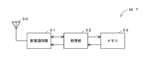
- FIG. 2 is a block diagram showing a circuit configuration common to the moving tag M and the fixed tag T described above.
- each of the tags M and T includes a communication antenna unit 30, a modem circuit 31, a microcomputer processing unit 32, a memory 33, and the like.
- the antenna unit 30 receives a radio wave including a carrier wave and a command signal from the antenna A on the reader / writer 2 side.
- the modem circuit 31 decodes the command signal from the radio wave received by the antenna unit 30 and outputs the command signal to the processing unit 32, and responds by the back scatter method based on the response signal output from the processing unit 32. This response signal is transmitted to the antenna A through the antenna unit 30.
- tag type information (a code indicating that it is a moving tag or a fixed tag) into which the memory 33 is incorporated is written in advance, and the radio wave from the antenna A is reflected in response to a command. Is stored (in this example, a gain setting value for deriving the degree of modulation of the backscatter). Further, information on the corresponding moving object is written in the memory of the moving tag M.
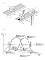
- Fig. 3 (1) shows an example in which the above RFID system is introduced to the production site.
- the moving body of this embodiment is a pallet P conveyed by the belt conveyor 10, and a moving tag M is attached to one side surface thereof.
- the antenna A of the reader / writer 2 is arranged at a position facing the moving tag M when the pallet P reaches a predetermined place on the conveyor 10.
- a stand 15 to which a fixed tag T is attached is disposed at a position facing the antenna A across the conveyor 10.
- the pallet P contains parts.
- a part type code As information on the corresponding moving body (pallet P), a part number, a quantity, a model number of a product to be incorporated, identification information on a site where the part is conveyed, and the like are written.
- a command for instructing reading of information (hereinafter referred to as “read command”) is repeatedly sent based on a command from the control device 1.
- the fixed tag T and the moving tag M read the information stored in the memory 33 of its own circuit, and output a response signal including the read information to the antenna A.
- the communication control unit 20 decodes information included in the response signal received by the antenna A, and transmits the decoded information to the control device 1 as read information.
- the control device 1 first extracts the tag type code included in the read information. When the type code of the moving tag M is extracted, the read information is analyzed in detail.
- the identification information of the parts transport destination is compatible with the conveyor 10, and if it is determined that the information does not match, alarm information is output. It also recognizes the part type code, quantity, etc., and sends the recognition result to a server that manages the production line.
- the pallet P of this embodiment is made of a material that allows radio waves to pass, such as synthetic resin or wood. Therefore, even when the pallet P reaches the front of the antenna A and the space between the antenna A and the fixed tag T is shielded, the radio wave from the antenna A passes through the pallet P and reaches the fixed tag T. Similarly, the radio wave reflected by the fixed tag T passes through the pallet P and reaches the fixed tag T. Therefore, the fixed tag T can always respond to a read command from the antenna A and output a response signal regardless of the position of the moving tag M. In consideration of these points, in this embodiment, the relationship shown in FIG. 3B is established between the signals received by the antenna A from the tags T and M by the setting process described later.
- FIG. 3B is a graph showing changes in the level of response signals received by the antenna A from the fixed tag T and the moving tag M in response to each read command.
- the reception level of the signal from the fixed tag T is stabilized at a substantially constant value, whereas the reception level of the signal from the moving tag M fluctuates in a mountain shape as the tag M moves. To do.
- the signal from the moving tag M is initially smaller than the signal from the fixed tag T, and a level difference of a predetermined value D or more is generated with respect to the signal from the fixed tag T.
- the signal received from the moving tag M increases as the moving tag M approaches the antenna A, and exceeds the signal from the fixed tag T.
- the signal received from the moving tag M while the pallet P, which is a moving body, passes the front of the antenna A (the period U in FIG. 3B corresponds to this) is the signal received from the fixed tag T.
- the signal received from the mobile tag M falls as the mobile tag M moves away from the antenna A, and the signal received from the fixed tag T becomes stronger again, and there is a difference of D or more between the respective reception levels. Occurs.
- the moving tag M and the fixed tag T of this embodiment respond to the read command from the antenna A at a certain timing, that is, immediately after receiving the read command, or when a predetermined time has elapsed since reception. Is output. For this reason, when the read command from the antenna A reaches a plurality of tags, the response signals from these tags may reach the antenna A almost at the same time. Since they are superimposed, the waveform of a signal with a strong reception level becomes dominant. In particular, when the difference in reception level between a certain response signal and another response signal is greater than or equal to D (hereinafter, this D is referred to as “reference level difference D”), the other signal is buried in the signal having the strongest level. Only the signal with the strongest level can be decoded. Therefore, even when a plurality of tags respond to the read command from the antenna A, it is possible to exclusively read a signal from one of the tags.
- the moving tag M is located near the front of the antenna A.
- the signal from the moving tag M is greater than the reference level difference D with respect to the signal from the fixed tag T. Therefore, the signal from the fixed tag T is buried in the signal from the moving tag M, and the signal from the moving tag M is substantially read. Therefore, during this period U, the information of the moving tag M can be reliably read.
- the signal from the fixed tag T becomes dominant with a difference of the reference level difference D or more with respect to the signal from the moving tag M.
- the signal from the tag M is buried in the signal from the fixed tag T, and the signal from the fixed tag M is substantially read. Therefore, even when a read command arrives at the mobile tag M located at a place where the antenna A should not be communicated, the information of the fixed tag T is read instead of the information of the mobile tag M. Can be prevented.
- the level difference between the signal from the moving tag M and the signal from the fixed tag T is the reference level difference. Smaller than D. Therefore, in these periods U X and U Y , it is not certain which information is read from which tag, and there is a possibility that both response signals interfere with each other and a reading error occurs.
- the change curve of a signal from the mobile tag M of this embodiment the width of the top portion is relatively long, the change of the leading edge and trailing edge is steep, received unstable period U X, U Y can be shortened.
- the length of the period U is sufficiently secured, no particular trouble occurs in reading the information of the mobile tag M.
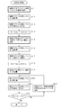
- FIG. 4 shows a procedure of processing performed by the control device 1 shown in FIG.
- the control device 1 repeatedly executes a loop of steps S1 to S6.
- step S1 a read command is passed to the reader / writer 2 for transmission.
- step S2 read information obtained by decoding the response signal is received from the reader / writer 2 that has received the response signal to the read command.
- step S3 the identification information in the read information is extracted and the corresponding tag type is recognized.
- step S4 If the identification information indicates the moving tag M ("YES" in step S4), the contents of the read information are analyzed, the above-described recognition process is executed (step S5), and the result is output ( Step S6). As a result, when the processing for one cycle is completed, the process returns to step S1, and transmission processing of the next read command is performed.
- step S4 if the identification information extracted from the read information indicates the fixed tag T (“NO” in step S4), the process skips steps S5 and S6 and returns to step S1.
- step S4 becomes “NO” continues, and the moving tag
- step S5 is performed.
- step S6 are performed.
- step S2 the algorithm relating to the above step S2 is set to wait for reception of read information until a certain waiting time elapses from transmission of the read command.
- step S2 can be ended before the time is up. Therefore, the processing time of the loop of steps S1 to S4 or steps S1 to S6 can be shortened, and with this, the time interval for transmitting the read command can be shortened. Therefore, even when the moving tag M moves at a high speed, information can be read without hindrance.
- the mobile tag M and the fixed tag T are communicated with the reader / writer 2 in order, and the level of the signal obtained by the antenna A from each of the tags M and T is measured. And according to these measurement results, the reflection intensity of the radio wave at the fixed tag T is adjusted by rewriting the set value of the gain in the memory 33 of the fixed tag T.
- FIG. 5 shows the procedure of the above setting process.
- steps S11, S15, and S19 indicated by double frames are performed by the user at the site, and the other steps are performed by the control device 1.
- communication with the tag is performed via the reader / writer 2.
- This process is started in a state where the fixed tag T is not installed.
- the user arranges the moving tag M (precisely, the pallet P to which the moving tag M is attached. The same applies to the following) at a place (near the front of the antenna A) to be communicated with the antenna A (step S11). ).
- a command for instructing the start of calculation is input to the control device 1.
- the control device 1 that has received the above command executes communication with the moving tag M n times (n ⁇ 1) to the reader / writer 2 and measures the level of the signal received from the moving tag M for each communication (step) S12). Specifically, the process of transmitting a test command to the reader / writer 2, the process of receiving a response signal to this command, and the process of measuring the level of the received response signal are executed n cycles, and the measured value every time To get.
- control device 1 calculates an average value S M1 of these measured values (step S13), and performs an operation of subtracting the reference level difference D and a predetermined margin value k from the obtained average value S M1 (Ste S14).
- the value R1 obtained by this calculation is stored in the internal memory of the control device 1 as the first reference value.
- the control device 1 displays a message notifying that the first stage processing is completed on a monitor (not shown).
- the user who confirmed this display changes the arrangement of the moving tag M to a place where the mobile tag M should not be communicated (step S15). As the place after the change, it is desirable to select a place close to the boundary with the place where the antenna A may be communicated.
- the user who has finished the operation of changing the arrangement of the moving tag M inputs a command for instructing the control device 1 to start computation.
- the control device 1 performs communication with the mobile tag M n times by the same process as in step S12, and measures the level of the signal received from the mobile tag M for each communication (step S16). .
- an average value S M2 of these n reception levels is calculated (step S17), and further, an operation of adding the reference level difference D and the margin value k to the average value S M2 is performed (step S18).
- the value R2 obtained by this calculation is stored in the internal memory of the control device 1 as the second reference value.
- the control device 1 displays a message notifying that the second stage processing has been completed on the monitor.
- the user who has confirmed this display moves the moving tag M to a place where the radio wave from the antenna A does not reach, and installs the fixed tag T at a place facing the antenna A with the conveyor 10 in between (step S19). Then, a command for instructing the control device 1 to start setting processing for the fixed tag T is input.
- the control device 1 that has received the above command performs communication with the fixed tag T n times by the same processing as in steps S12 and S16, and measures the level of the signal received from the fixed tag T for each communication ( Step S20). Then, an average value S T of each measurement value (step S21), and the value of this S T, is compared with the reference value R1, R2.
- step S22 is "YES"
- the reception level from each tag M T is 3 (2
- the processing is terminated assuming that the relationship shown in FIG.
- step S22 when the average value S T reaches the second reference value R2 or less, or the first reference value R1 or more (step S22 is "NO"), the controller 1 through the reader-writer 2 fixed A command for changing the gain setting value is transmitted to the tag T (step S23). Specifically, if the average value S T is at R2 or less, it transmits a command instructing to increase the gain setting, when the average value S T is R1 or, to lower the gain settings Send the command to instruct.
- the fixed tag T that has received the above command changes the gain setting value in its own memory 33 according to the contents of the command, and returns a response signal indicating that the change has been completed.
- the control device 1 executes steps S20 to S22 again.
- step S20 at this time, a signal having an intensity based on the changed set value is received from the fixed tag T.
- the average value S T of the level of a signal received from the fixed tag T falls between the reference value R1 and R2, repeating a loop of steps S20 ⁇ 23, the process ends thereafter.
- the fixed tag T when the system is introduced, the fixed tag T is at a level buried in a signal received by the antenna A from the moving tag M located at a place where the antenna A should be communicated. It can be installed in a state where it can receive a signal at a level that causes the signal received by the antenna A to be buried from the moving tag M located at a place where it should not communicate with the antenna A. Also, after the introduction of the system, the reception state from each tag M, T fluctuates due to environmental changes, etc., and the relationship shown in FIG. 3 (2) is not established between the signals received from each tag M, T. In this case, the relationship between the levels of the signals can be returned to an appropriate state by executing the setting process again.
- the setting process is not limited to that shown in FIG. 5, and the gain setting value of the mobile tag M may be adjusted based on the level of the signal received from the fixed tag T.
- determines the modulation degree based on the gain set value in the processing unit 32 of the fixed tag T is not limited to this, the control unit 1 based on the value of the average value S T modulation The adjustment value of the degree may be obtained, and a command including this adjustment value may be transmitted to the fixed tag T.
- the reflection intensity of the radio wave is adjusted by changing the modulation degree of the backscatter, but the adjustment method is not limited to this.
- a variable attenuator may be provided between the antenna unit 30 of the fixed tag T and the modulation circuit 31, and the amount of attenuation may be adjusted.
- a variable capacitor may be incorporated in the circuit of the antenna unit 30, and the capacity of the variable capacitor may be changed according to the change of the gain setting value.
- FIG. 6A shows another example of introduction of the RFID system of the first form.
- information is read from the moving tag M attached to the pallet P conveyed by the conveyor 10.
- M B is likely to respond.
- another conveyor 11 is installed next to the conveyor 10, and there is a possibility that a read command from the antenna A reaches the moving tag Mout located on the adjacent conveyor 11 and a response signal is returned. is there.
- the antenna A is the The relationship shown in FIG. 6 (2) is established between signals received from the tags.
- the signal received from the fixed tag T is maintained at a substantially constant level.
- Signals received from the moving tags M A and M B on the conveyor 10 are transmitted while the moving tags M A and M B are located near the front of the antenna A, similarly to the moving tag M in FIG. becomes a level that makes buried a signal from the fixed tag T, the mobile tag M a, when the M B are away from the front of the antenna a over a certain distance has a level buried in the signal from the fixed tag T.
- the exception of periods U Z in the graph when a signal from one of the mobile tag is in the dominant than the signal from the fixed tag T with a difference equal to or larger than the reference level difference D, the signal from the other mobile tag Is below the signal from the fixed tag T. Therefore, in each of the mobile tags M A and M B , it is possible to ensure a sufficiently long period during which the response signal can be exclusively read by the antenna A.
- the signal received from the moving tag M out is always from the fixed tag T.
- the level difference with respect to the signal from the fixed tag T is greater than the reference level difference D, which is weaker than the received signal.
- the response signal is the response signal from the fixed tag T or the moving tags M A and M that have become dominant.
- the signal is buried in the response signal from B and cannot be decoded. Therefore, it is possible to information of the mobile tag T out is prevented from being read as information on the pallet P being conveyed by the conveyor 10.
- an antenna and a fixed tag are arranged on the conveyor 11 as well as the conveyor 10, and the antenna 11 of the conveyor 10 is connected to the fixed tag of the conveyor 11. Read command may arrive. However, since the level of the signal received by the antenna A of the conveyor 10 from the fixed tag of the conveyor 11 is the same low level as the signal from the moving tag Mout , the information of the fixed tag of the conveyor 11 is The information of the fixed tag T is not erroneously recognized.
- the fixed tag T is disposed at a location facing the antenna A with the conveyor 10 in between.
- FIG. 7 in response to a signal from the moving tag M, FIG. If the same relationship as shown in the graph of 6 (2) can be established, it is not necessary to limit the installation location of the fixed tag T.
- a stand 15 to which the fixed tag T is attached may be provided between the antenna A and the conveyor 10.
- the fixed tag T can be provided integrally with the antenna A or the communication control unit 20 of the reader / writer 2.
- the transmission level and interval of the moving tag M are adjusted without arranging the fixed tag T.
- the system of the second form is for managing entry / exit. An example of system introduction is shown in FIG.
- the object is to prevent erroneous delivery of cargo when cargo is loaded into a cargo container by a forklift B.
- carry-in routes R1, R2, R3,... Rn for a plurality of freight containers (not shown) having different delivery destinations are arranged in parallel.
- reader / writer antennas A1 to An are provided on one side, and fixed tags T1 to Tn are provided at locations facing the antennas A1 to An across the paths R1 to Rn.
- a pair of indicator lights 9a to 9n and 10a to 10n are provided separately on both sides of the routes A1 to An at the rear end positions (positions before the gate) of the routes A1 to An.
- the indicator lights 9a, 9b, 9c,... 9n arranged on the left hand with respect to the traveling direction of the forklift B emit blue light indicating that passage is permitted, and the indicator lights 10a, 10b, 10c arranged on the right hand. ,... 10n emits red light indicating that passage is not permitted.
- the moving tag M is attached to the forklift B at a location that is in a relationship facing the antennas A1 to An when entering the paths R1 to Rn.
- the tags M, T1 to Tn and the antennas A1 to An communicate with each other by performing mutual modulation processing and demodulation processing using radio waves in the UHF band.
- Each of the tags M and T1 to Tn is a passive RFID tag, but a semi-passive RFID tag can also be used.
- the moving tag M includes, in advance, a type code indicating that it is a moving tag, and information on the corresponding moving body, such as an identification number of a route through which the forklift B should pass, a product number of a delivery product, a customer code, and a customer factory. Code and other necessary information is written.
- a type code indicating a fixed tag and a corresponding route code are written.
- FIG. 9 is a block diagram showing a system configuration (however, tags T1 to Tn and M are not shown) in the above embodiment.
- the reader / writer 200 used in the RFID system of this embodiment is configured by antennas A1 to An of the paths R1 to Rn and a communication control unit 201 common to these antennas A1 to An.
- a main control board 101 and a light source control board 102 are incorporated in the control device 100.
- the main control board 101 includes a CPU 103, a memory 104, a timer 105 for timing processing described later, and the like.
- the communication control unit 201 of the reader / writer 200 is connected to the main control board 101 via an interface such as RS232C.
- peripheral devices such as a keyboard 106, a mouse 107, and a display 108 and a light source control board 102 are connected to the main control board 101.
- the above-mentioned indicator lamps 9a to 9n and 10a to 10n are connected to the light source control board 102.
- the memory 104 of the main control board 101 stores a program used for calculation, a storage area for temporarily storing read information decoded from response signals received by the antennas A1 to An, and a register constituting a soft timer An area, a database for storing information read from the moving tag, a storage area for storing processing history data (log data), and the like are provided. Further, in the memory 104, information such as a product number of a delivery product that is allowed to pass, a customer code of a corresponding container, and a factory code is registered for each of the routes R1 to Rn.
- the CPU 103 of the main control board 101 causes the communication control unit 201 of the reader / writer 200 to operate each of the antennas A1 to An in order to transmit a read command and receive a response signal, and to perform communication.
- the control unit 201 acquires the read information decoded from the response signal. Further, the CPU 103 determines the type of the read information acquired, and if it is determined that the read information is the moving tag M, the read information is checked by comparing the read information with the registration information corresponding to the antenna that received the information. Judging the suitability of
- the read commands output from the antennas A1 to An of the respective paths R1 to Rn reach the fixed tags T1 to Tn and the movement tag M of the corresponding path, and the fixed tags of other paths. And may also reach mobile tags.
- any of the antennas A1 to An reliably receives a response signal from the mobile tag M located at a place to communicate with the antennas A1 to An, and the mobile tag M located on another route, etc. Reading of a response signal from a tag located in a place where communication should not be performed can be prevented.
- an initial value “1” is set in a counter i for specifying a processing target route.
- a read command is transmitted to the antenna Ai (antenna A1 in the initial state).
- the fixed tags T1 to Tn and the moving tag B of this embodiment return a response signal at a certain timing when receiving the read command.
- the CPU 103 of the control device 100 causes the timer 105 to start measuring time in response to the transmission of the read command, and the time counting time is set to a predetermined upper limit value (set to be longer than the time required for returning the response signal by a predetermined time). It waits for transmission of reading information until it reaches (steps S103, S104).
- step S103 determines the type of the tag corresponding to the information based on the data structure of the received read information (step S105).
- step S105 determines that the read information is information of the fixed tag Ti. In this case, since step S105 is “NO”, the counter i is updated (steps S111 and S112), and the process returns to step S102. If the counter i has reached n, the process returns from step S111 to step S101 to return i to the initial value “1”, and then proceeds to step S102.
- step S105 is “YES” and the process proceeds to step S106.
- step 106 various data are separated and extracted from the read information, and after scrutinizing whether there is data corruption or the like, it is stored in the memory 104 as temporary data. Further, in the next step S107, the temporarily stored data is checked against registered data related to the route Ri.
- the normal process includes a process of sending a control command signal for operating the blue indicator lamp of the route Ri to the light source control board 102, a process of storing various data extracted from the read information in a database, and these processes. This includes the process of writing the log data into the log data.
- step S108 if a mismatch between the two types of data is recognized by the verification process, step S108 is “NO”, and the process proceeds to step S110 when an abnormality occurs.
- This abnormal process includes a process of sending a control command signal for operating the red indicator lamp of the route Ri to the light source control board 102, a process of displaying the occurrence of the abnormality on the display 108, and various types extracted from the read information. This includes a process of saving data in a database, a process of writing the execution of these processes in log data, and the like.
- step S104 If propagation of radio waves between the antenna Ai and the fixed tag Ti is hindered for some reason, the read information is acquired even when the waiting time from the read command transmission (step S102) reaches the upper limit value. It becomes a state that can not be. In this case, step S104 becomes “YES”, the process proceeds to step S110, and processing at the time of abnormality is performed.
- step S110 when the information of another fixed tag is read because the fixed tag Ti of the route Ri has failed, the route identification information included in the read information matches the counter i. It will be in a state that does not. When such an inconsistency occurs, an abnormality process different from that in step S110 is performed.
- read commands are sent in order from the antennas A1 to An of the paths R1 to Rn, and read information decoded from the response signals received by the antennas A1 to An is obtained, and this read
- the information is information on a moving tag
- the recognition result is used using the indicator lamps 9a to 9n, 10a to 10n, etc.
- the control device 100 accurately recognizes the route on which the forklift B has entered, Appropriateness of the entry position can be correctly determined.
- the processing for each of the paths R1 to Rn is performed one by one, but unless radio waves are shielded between the active antenna Ai and the fixed tag Ti facing the antenna Ai,
- the fixed tag Ti can be made to react to the read command. Therefore, even when the moving tag B is not included in the route Ri corresponding to the antenna Ai, a response signal from the fixed tag Ti can be quickly obtained in response to the transmission of the read command, and the processing for each route R1 to Rn is performed. It is possible to shorten the time until one completes. Further, the cost can be reduced as compared with the case where a reader / writer is provided for each of the paths R1 to Rn.
- a communication control unit may be combined for each of the antennas A1 to An of the paths R1 to Rn, and processing for each of the paths R1 to Rn may be performed in parallel.
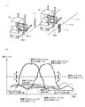
- FIG. 11 (1) is an example in which this principle is applied, and a pair of moving tags M FW and M BK are attached to one side of the forklift B side by side at a predetermined interval.
- the control device 100 recognizes whether the forklift B has moved forward or backward based on the order in which information is read from these moving tags M FW and M BK .
- the relationship shown in FIG. 11 (2) is established for the signal received by the antenna Ai from each tag.
- FIG. 11B is a graph showing changes in the level of the signal received by the antenna Ai from each tag when the forklift B moves forward on the route Ri. Also in this example, the level of the signal received from the fixed tag Ti is maintained substantially constant. Of each of the moving tags M FW and M BK , the signal from the moving tag M FW that reaches the front of the antenna Ai first is received first, and then the signal from the moving tag M BK is received. Become. Further, in both of the movement tags M FW and M BK , a period in which the signal is dominant with a level difference equal to or greater than the reference level difference D is secured with respect to the signal from the fixed tag Ti and the other movement tag. .
- FIG. 11 (1) shows a forklift B that stops on the side of the route Ri
- FIG. 11 (2) shows an antenna Ai from the moving tags M FW1 and MBK1 attached to the forklift B.
- the change in the level of the received signal is shown.
- Each of these signals is always weaker than the signal from the fixed tag Ti, and has a level difference equal to or greater than the reference level difference D with respect to the signal from the fixed tag Ti. Therefore, the signals from these moving tags M FW1 and M BK1 are buried in the signal from the fixed tag Ti and cannot be decoded regardless of the presence or absence of the moving tag on the path Ri. Therefore, the information of the mobile tags M FW1 and M BK1 is not read from the signal received by the antenna Ai.
- the relationship between the above signals is also realized by setting processing according to FIG. 5 and adjusting the intervals of the movement tags M FW and M BK .
- This adjustment moves the tag M FW entering the path Ai, M BK, because that information when it came to place both should communicate with the antenna Ai (front of the antenna) is read, each of the mobile tag M FW, by carrying out reading process with respect to M BK in the correct order, it is possible to accurately recognize the traveling direction of the forklift B.
- the present invention is not limited to this, and after the moving tag is specified by the read command, It is also possible to send a write command designating this movement tag as a communication target and write new information to the movement tag.
- the forward and backward movement of the moving body is recognized by the reading process for the pair of moving tags M FW and M BK attached to the moving body (forklift B). It is also possible to construct a system that recognizes the direction of travel of the subject. An example is shown in FIG.
- the antenna 211 of the reader / writer 210 is attached to the vehicle body of the vehicle C, and a pair of fixed tags T DN and T UP are arranged along the length direction of the traveling path RD of the vehicle C (each Tags T DN and T UP are embedded, for example, under the road surface of travel path RD.) Further, inside the vehicle C, a communication control unit 212 and a control device 110 of the reader / writer 210 are provided.
- An arrow F in the figure indicates the upward direction of the vehicle C.
- the tag T UP positioned on the upstream side is referred to as “uplink tag T UP ”
- the tag T DN positioned on the downstream side is referred to as “downlink tag T DN ”.
- type information indicating its own type is stored in each of the tags T UP and T DN .
- the control device 110 causes the reader / writer 210 to repeatedly transmit a read command and receive a response signal, input read information decoded from the response signal, and select any tag depending on the type information. It is determined whether it is the information. Then, when the information of the down tag T DN is obtained after the information of the up tag T UP is obtained, the vehicle C recognizes that it is moving along the down direction, and obtains the information of the down tag T DN. Then, when the information of the up tag T UP is acquired, it is recognized that the vehicle C is moving along the up direction.
- each tag T UP so that the relationship shown in FIG. 12 (2) is established in the signal received by the antenna 211 from each tag T UP , T DN .
- adjusting the spacing between the reflection intensity and tags radio in T DN For example, first, the location of each tag T UP , T DN is determined, and each tag T UP , T DN is provisionally placed one by one at a predetermined location, and the antenna 210 should communicate with the temporarily placed tag. The reception level at the place and the reception level when the antenna 210 is at the place to communicate with the other tag are measured. And based on each measured value, the reflection intensity of the radio wave in each tag TUP , TDN is adjusted.
- P0 in the graph of FIG. 12 (2) corresponds to the minimum reception level required to decode information from the response signal.
- the response signal from the downlink tag T DN is first received, and then the response signal from the uplink tag T UP is received.
- the reception level of the signal from each of the tags T DN and T UP changes in a mountain shape, and one of the signals is different from the other signal by a reference level difference D or more with the exception of the period U V in the figure. It will be in a dominant state.
- a sufficient period of time can be secured for any of the tags T UP and T DN so that a signal at a level that can bury the signal from the other tag can be transmitted to the antenna 211. Therefore, the reading process for each of the tags T UP and T DN can be performed without mistake in order. Therefore, the traveling direction of the vehicle C can be correctly recognized.
- three or more fixed tags can be arranged on the travel route RD. Even when the number of fixed tags is increased, as in the above example, a sufficient period is secured for each tag so that a signal at a level that can bury signals from other tags can be transmitted to the antenna. As described above, the reflection intensity of radio waves at each tag and the interval between tags are set.
Landscapes
- Engineering & Computer Science (AREA)
- Physics & Mathematics (AREA)
- Toxicology (AREA)
- Health & Medical Sciences (AREA)
- Computer Networks & Wireless Communication (AREA)
- Theoretical Computer Science (AREA)
- General Physics & Mathematics (AREA)
- Computer Vision & Pattern Recognition (AREA)
- Artificial Intelligence (AREA)
- Electromagnetism (AREA)
- General Health & Medical Sciences (AREA)
- Warehouses Or Storage Devices (AREA)
- Radar Systems Or Details Thereof (AREA)
- Near-Field Transmission Systems (AREA)
Abstract
移動体(パレット)(P)が進行する経路の近傍にアンテナ(A)を配置し、アンテナ(A)からの電波を受信可能な位置に固定タグ(T)を配置する。移動体(P)に取り付けられた移動タグ(M)および固定タグ(T)は、アンテナ(A)からの読出コマンドを受信すると、一定のタイミングで応答信号を返送する。アンテナ(A)が固定タグ(T)から受信する信号はほぼ一定になるが、移動タグ(M)がアンテナ(A)と交信すべき場所に位置する間は、固定タグ(T)からの信号は移動タグ(M)からアンテナ(A)に送信される信号の中に埋もれて読取が不可能な状態になる。一方、移動タグ(M)がアンテナ(A)から一定の距離以上離れると、移動タグ(M)からの信号が固定タグ(T)からの信号の中に埋もれて読取が不可能な状態になる。
Description
本発明は、移動する物体(以下、「移動体」という。)を、その移動途中に認識するためのRFID(Radio Frequency Identification)システムに関する。
RFIDシステムは、RFIDタグ(以下、単に「タグ」という場合がある。)とリーダライタとの間で電波を介した交信を行うものである。特に、パッシブタイプやセミパッシブタイプのRFIDタグを用いたシステムは、リーダライタからの電波によりRFIDタグを起動して交信を行わせることができることから利便性が高く、様々な目的に使用されている。
たとえば、工場では、管理対象の物品の1つ1つにRFIDタグを取り付けて、コンベアにより搬送すると共に、コンベアの近傍位置にリーダライタのアンテナを設置し、物品の移動に伴ってアンテナの交信領域にRFIDタグが入る都度、そのRFIDタグとアンテナとの間で交信を行って、情報の読み書き処理を実施する(特許文献1を参照。)。
また、入退出を管理する目的で、出入口への通路にリーダライタのアンテナを設置し、通路を進行する移動体(人または物品)に取り付けられたRFIDタグをアンテナからのコマンドに反応させるようにしたシステムも知られている。
たとえば、特許文献2には、近接した複数のゲートを通過するRFIDタグから識別情報を取得するシステムにおいて、ゲート毎に設置されたアンテナから読出信号を送信し、読出信号を受信した全てのRFIDタグからの応答信号によりID情報を取得し、それらの中から不要なRFIDタグからのID情報を除外するフィルタリング処理を実施することが記載されている。
また、特許文献3には、人が通過する複数のゲートにそれぞれ質問器(リーダライタ)と固定タグとを設置し、各ゲートの質問器において、ゲートを通る人が所持する移動タグおよび固定タグを単位時間あたりに複数回同時期に読み出し、各タグとの通信の可否や通信成功率によって各ゲートにおける移動タグの有無を判別することが記載されている。さらに、特許文献3には、固定タグとの通信が困難で移動タグが存在しないという判別がなされた場合に、タグを所持しない人物により固定タグへの電波が遮断されたと認識することや、固定タグおよび移動タグにそれぞれ異なるタイムスロットを割り当てることによって、質問器からのコマンドに対してタグの種毎にタイミングをずらして応答させることが記載されている。
本発明の発明者らは、フォークリフトなどの車両の入退出を管理する目的でRFIDシステムを開発するにあたり、図13に示すようなシステムを構成し、その有用性を検証した。このシステムでは、近接して並設された複数の経路R1~Rnの一側にリーダライタのアンテナA1~Anをそれぞれ配備し、フォークリフトBにRFIDタグtを取り付ける。RFIDタグtには、たとえばフォークリフトBにより搬入される貨物に関する情報が予め書き込まれている。
各アンテナA1~Anは読出コマンドを順に送信すると共に、所定の待ち時間が経過するまでタグtからの応答信号の受信に待機する。待ち時間以内に応答信号を受信した場合には、その応答信号に含まれる情報を読み取って分析し、搬入の是非をチェックする。
ところが、上記の方法によると、図14に示すように、実際にフォークリフトBが入った経路(この例では経路R2)とは異なる経路(この例では経路R3)のアンテナA3からの電波に経路R2のRFIDタグtが反応し、その結果、誤った情報の読取が行われて、認識結果に誤りが生じることが判明した。
特許文献2に記載された発明では、ゲートの周辺に存在するタグからの信号が受信されることを考慮して、毎回の読取信号の送信に対して応答可能な全てのタグからの応答信号を受信して、各ID情報を取得し、同一のID情報毎に応答信号の強度の時系列変化を求めて、この変化の波形に基づきゲートを正しく通過したタグからの応答信号を判別するようにしている。しかし、このような方法では、処理が複雑になり、処理に要する時間も長くなるので、高速の処理が要求される用途には不向きである。
特許文献3に記載された発明では、質問器からのコマンドに対し、移動タグおよび固定タグをそれぞれ異なるタイミングで応答させ、移動タグとは交信できたが固定タグとは交信できなかった場合には移動体は当該アンテナと同じ通路に位置し、移動タグおよび固定タグの双方と交信できた場合には移動体は当該アンテナとは異なる通路に位置すると判断する。これにより、各通路の移動タグを精度良く検出することが可能になる。
しかし、特許文献3に記載された発明では、移動タグからの応答を受け付ける時間と固定タグからの応答を受け付ける時間とが個別に設定される上に、各タグとの交信状況を分析する時間をとる必要があり、特許文献2と同様に、処理が複雑で時間がかかる。よって特許文献3に記載された発明も、高速の処理が要求される用途には適していない。
また、特許文献3に記載された発明では、アンテナと固定タグとの間に移動体が入ることによって電波が遮蔽されることを前提としているが、電波を通過させる特性を持つ物体が移動体となる場合もある。またアンテナからの電波が反射するなどして、予期しない方向にまでアンテナからの電波が伝搬し、その結果、コマンドを送信したアンテナに交信対象外のタグからの応答信号が届く場合もある。これらの問題に対する対策について、特許文献3には何も記載されていない。
本発明は上記の問題点に着目し、簡易な構成と簡単な処理とにより、移動体を認識するために必要なRFIDタグのみとの交信を可能にすると共に、処理時間を短縮することを課題とする。
本発明は、認識対象の移動体が進行する経路の近傍に設けられたアンテナを含む交信処理装置と、移動体に関連する情報が書き込まれて当該移動体と共に移動する移動RFIDタグ(以下「移動タグ」と略す。)と、交信処理装置の動作を制御すると共に交信処理装置が移動タグとの交信により得た読取情報を交信処理装置から取得し、この読取情報を用いて移動体に関する認識処理を行う制御装置とを有するRFIDシステムに適用される。
上記のRFIDシステムにおいて、交信処理装置は、たとえば、アンテナとこのアンテナの動作を制御する交信制御部とを有するリーダライタにより構成される。また、通常のリーダライタは一対のアンテナと交信制御部とにより構成されるが、この発明の交信処理装置には、複数のアンテナとこれらのアンテナを統括制御する制御部とを含めることもできる。または、アンテナと交信制御部との組み合わせを複数組含めることもできる。
本発明によるRFIDシステムには、所定の場所に固定配備される固定RFIDタグ(以下「固定タグ」と略す。)がさらに含まれる。この固定タグは、アンテナと交信すべき場所に位置する移動タグから当該アンテナが受信する信号に埋もれるレベルであって、アンテナと交信すべきでない場所に位置する移動タグから当該アンテナが受信する信号を埋もれさせるレベルの信号を当該アンテナに届ける。
さらに、本発明の移動タグおよび固定タグは、それぞれアンテナからのコマンドに対して一定のタイミングで応答する。制御装置は、交信処理装置に、読出コマンドを送信して当該コマンドに対するRFIDタグからの応答信号を受信する処理を繰り返し実行させると共に、応答信号を受信した交信処理装置から移動タグの応答信号による読取情報を取得したとき、その読取情報を用いて前記認識処理を実行する。
上記のシステムによれば、アンテナからの読出コマンドが移動タグおよび固定タグの双方に届いた場合には、各RFIDタグは、その種別によらず、一定のタイミングで応答する。よって、これらのタグからの応答信号はアンテナにほぼ同時に届くが、移動タグがアンテナと交信すべき場所に位置している場合には、固定タグから受信した応答信号は移動タグから受信した応答信号に埋もれて読取が不可能な状態になり、移動タグからの応答信号による情報が読み取られる。一方、移動タグがアンテナと交信すべきでない場所に位置している場合には、移動タグから受信した応答信号は固定タグからの応答信号に埋もれて読取が不可能な状態となり、固定タグからの応答信号による情報が読み取られる。
よって、移動体の移動に伴ってアンテナと交信すべき場所に入った移動タグの情報を確実に読み取ることができる。また、アンテナと交信すべきでない場所にある移動タグに読出コマンドが届いて、その移動タグがコマンドに応答しても、当該移動タグからの応答信号は固定タグからの応答信号に埋もれてしまうので、アンテナと交信すべきでない場所に位置する移動タグの情報が読み取られるのを防ぐことができる。
アンテナからのコマンドに対し複数の移動タグが応答した場合でも、そのうちの1つのみがアンテナと交信すべき場所に位置するのであれば、そのタグからの応答信号のみから情報を読み取ることができる。また、読出コマンドを送信したアンテナは、移動タグからの応答信号を受信できない場合でも、固定タグからの応答信号を受信することができるので、応答信号の受信待ちによって処理が長引くおそれがない。よって、処理時間を短縮することができ、高速処理が要求される現場にも容易に対応することが可能になる。
上記のシステムの好ましい一実施態様では、移動体を進行させるために設定された複数の経路毎にアンテナおよび固定タグが設けられる。また、制御装置は、各経路のアンテナにそれぞれ読出コマンドの送信および応答信号の受信を実施させると共に、読取情報として移動タグからの応答信号による情報を取得したとき、その読取情報を含む応答信号を受信したアンテナに対応する経路に移動体が位置すると認識する。
上記の実施態様によれば、いずれの経路においても、その経路に設けられた固定タグによって、他の経路の移動タグから受信する信号が読み取られることがなくなり、対応する経路内でアンテナと交信すべき場所に位置する移動タグの情報を安定して読み取ることが可能になる。このように、移動タグの情報を、その移動タグが入った経路のアンテナのみで確実に読み取ることができるので、移動体の位置を誤りなく認識することが可能になる。
さらに上記の実施態様における制御装置は、各経路のアンテナに、読出コマンドの送信および応答信号の受信を順に実施させると共に、読出コマンドを送信したアンテナが応答信号を受信したことに応じて次のアンテナに読出コマンドを送信させる。本発明によれば、移動タグが存在しない経路のアンテナも、対応する固定タグからの応答信号を読出コマンドの送信後に速やかに受信することができるので、各アンテナによる受信処理が一巡するのに必要な時間を大幅に短縮することができる。
別の観点の実施態様では、制御装置は、移動タグの読取情報を取得したとき、その読取情報が当該読取情報を含む応答信号を受信したアンテナが配備される経路に整合するか否かを判別する判別手段と、この判別手段による判別結果を出力する出力手段とを、さらに具備する。この実施態様によれば、たとえば、移動体の進路の成否を、ランプやブザーなどにより報知することができる。また、移動タグに書き込まれている経路とは異なる経路に移動体が進入した場合には、それを確実に検出して警報を出力したり、ゲートを閉鎖するなどの対応をとることが可能になる。
さらに別の観点の実施態様では、移動RFIDタグおよび固定RFIDタグの少なくとも一方に、アンテナからのコマンドに対して応答する際の電波の反射強度を、当該反射強度の変更を求めるコマンドをアンテナから受信したことに応じて変更する機能が設けられる。
この実施態様によれば、アンテナと交信すべき場所に配備された移動タグ、アンテナと交信すべきでない場所に配備された移動タグ、および所定の場所に配置された固定タグのそれぞれに対する交信処理を行って、アンテナが各タグから受信する信号のレベルを計測し、これらの計測値に基づき電波の反射強度を調整することができる。
したがって、たとえばシステムを導入した際に上記の処理を実施すれば、固定タグからアンテナに届けられる信号のレベルを、アンテナと交信すべき場所に位置する移動タグから当該アンテナが受信する信号に埋もれるレベルであって、アンテナと交信すべきでない場所に位置する移動タグから当該アンテナが受信する信号を埋もれさせるレベルに設定することが可能になる。また、システムの導入後に各タグからの受信状態が変動した場合にも、上記の処理によって、アンテナが各タグから受信する信号のレベルの関係を良好な状態に戻すことが可能になる。
本発明によれば、アンテナからのコマンドを受信可能な場所に固定タグを配置し、この固定タグおよび移動タグからアンテナに届く信号のレベルの関係を調整することによって、交信すべきでない場所に位置する移動タグの情報が読み取られるのを防止し、読み出しの必要がある情報を確実に取得して、安定した認識処理を実施することができる。また、応答信号を受信する処理や受信した信号から読取情報を抽出する処理がきわめて簡単になるので、処理時間を短縮することができ、処理の高速化が要求される用途にも容易に対応することが可能になる。
以下、本発明が適用されたRFIDシステムについて2つの実施形態をあげ、システムの導入例と共に説明する。
<第1形態>
第1形態のRFIDシステムは、一定の方向に進行する移動体を検出し、その移動体に対して所定の認識処理を実施する目的に使用される。具体的なシステムは、図1に示すように、2種類のRFIDタグ(移動タグMおよび固定タグT)、リーダライタ2、制御装置1などにより構成される。
<第1形態>
第1形態のRFIDシステムは、一定の方向に進行する移動体を検出し、その移動体に対して所定の認識処理を実施する目的に使用される。具体的なシステムは、図1に示すように、2種類のRFIDタグ(移動タグMおよび固定タグT)、リーダライタ2、制御装置1などにより構成される。
リーダライタ2には、アンテナAおよび交信制御部20が含まれる。なお、以下に示す導入例では、アンテナAと交信制御部20とが別体となるが、これに代えて両者が一体になったタイプのリーダライタを使用してもよい。
各RFIDタグM,TとアンテナAとは、UHF帯域(860~960MHZ程度)の電波を用いて相互に変調処理や復調処理を行うことにより、交信を実施する。移動タグM、固定タグTは、いずれもパッシブタイプであるが、これに限らず、セミパッシブタイプのRFIDタグを用いてもよい。
移動タグMは、移動体に取り付けられて、当該移動体と共に移動する。固定タグTは、アンテナAから適度な強度の電波を受信する場所に固定配備される。
制御装置1の実体は、専用のプログラムがインストールされたパーソナルコンピュータである。交信制御部2には、マイコンや送受信回路が組み込まれ、制御装置1からの指示に応じて、アンテナAから読出コマンドを送信する処理と、この読出コマンドに対するタグM,Tからの応答信号を受信して当該信号に含まれる情報を復号する処理とを繰り返しながら、復号された情報を読取情報として制御装置1に送信する。制御装置1は、移動タグMからの読取情報を取得すると、この情報を用いて移動体に対する認識処理を実行する。
図2は、上記の移動タグMおよび固定タグTに共通の回路構成を示すブロック図である。この図2に示すように、各タグM,Tには、交信用のアンテナ部30、変復調回路31、マイクロコンピュータによる処理部32、メモリ33などが含まれる。
アンテナ部30は、リーダライタ2側のアンテナAから搬送波およびコマンド信号を含む電波を受信する。変復調回路31は、アンテナ部30が受信した電波からコマンド信号を復号して処理部32に出力すると共に、処理部32から出力された応答信号に基づきバックスキャッタ方式で応答する。この応答信号はアンテナ部30を介してアンテナAへと伝えられる。
メモリ33には、あらかじめ、当該メモリ33が組み込まれるタグの種別情報(移動タグまたは固定タグであることを示すコード)が書き込まれるほか、コマンドへの応答のためにアンテナAからの電波を反射させるときの反射強度を決めるための設定値(この例では、バックスキャッタの変調度を導き出すための利得の設定値)が格納されている。さらに移動タグMのメモリには、対応する移動体に関する情報が書き込まれる。
図3(1)は、上記のRFIDシステムを生産現場に導入した例を示す。この実施例の移動体はベルトコンベア10により搬送されるパレットPであり、その一側面に移動タグMが取り付けられる。リーダライタ2のアンテナAは、パレットPがコンベア10上のあらかじめ定められた場所に到達したときに移動タグMに対向する位置に配備される。アンテナAにコンベア10を挟んで対向する位置には、固定タグTが取り付けられたスタンド15が配備される。
図3(1)には示されていないが、パレットPには部品が収納されている。移動タグMには、対応する移動体(パレットP)に関する情報として、部品の種別コード、品番、数量、組み込まれる製品の型番、部品が搬送される現場の識別情報などが書き込まれる。
アンテナAからは、制御装置1からの指令に基づき、情報の読出を指示するコマンド(以下「読出コマンド」という。)が繰り返し送出される。固定タグTおよび移動タグMはこの読出コマンドを受信すると、自回路のメモリ33に格納されている情報を読み出し、読み出された情報を含む応答信号をアンテナAに対して出力する。交信制御部20は、アンテナAが受信した応答信号に含まれる情報を復号し、読取情報として制御装置1に送信する。これを受信した制御装置1では、まず読取情報に含まれるタグの種別コードを抽出し、移動タグMの種別コードを抽出した場合には、読取情報を詳細に分析する。そしてたとえば、部品の搬送先の識別情報がコンベア10に適合しているか否かを判別し、適合しないと判断した場合には警報情報を出力する。また、部品の種別コードや数量などを認識し、その認識結果を生産ラインを統括するサーバなどに送信する。
この実施例のパレットPは、合成樹脂や木質材など、電波を通過させる材料により形成される。このため、アンテナAの正面にパレットPが到達してアンテナAと固定タグTとの間の空間が遮蔽された場合でも、アンテナAからの電波はパレットPを通過して固定タグTに届く。固定タグTが反射した電波も同様に、パレットPを通過して固定タグTに届く。したがって、固定タグTは、移動タグMの位置に関わらず、アンテナAからの読出コマンドに常に反応して応答信号を出力することができる。これらの点を考慮して、この実施例では、後記する設定処理によって、アンテナAが各タグT,Mから受信する信号の間に図3(2)に示すような関係を成立させる。
図3(2)は、アンテナAが毎回の読出コマンドに対して固定タグTおよび移動タグMから受信する応答信号のレベルの変化をグラフにより表したものである。
このグラフに示すように、固定タグTからの信号の受信レベルはほぼ一定の値で安定するのに対し、移動タグMからの信号の受信レベルは当該タグMの移動に伴って山状に変動する。
具体的には、移動タグMからの信号は、最初のうちは固定タグTからの信号より小さく、また固定タグTからの信号に対して所定値D以上のレベル差が生じる。移動タグMから受信する信号は移動タグMがアンテナAに近づくにつれて高まり、固定タグTからの信号を上回る状態になる。特に、移動体であるパレットPがアンテナAの正面を通過する間(図3(2)中の期間Uがこれに相当する)に移動タグMから受信する信号は、固定タグTから受信する信号に対し、D以上のレベル差をもって優勢になる。その後に移動タグMから受信する信号は、当該移動タグMがアンテナAから遠ざかるにつれて下降し、再び、固定タグTから受信する信号の方が強くなり、それぞれの受信レベルの間にD以上の差が生じる。
この実施例の移動タグMおよび固定タグTは、アンテナAからの読出コマンドに対し、一定のタイミング、すなわち読出コマンドの受信後直ちに、または受信から予め定められた一定時間が経過したときに応答信号を出力する。このためアンテナAからの読出コマンドが複数のタグに届いた場合には、これらのタグからの応答信号がほぼ同時にアンテナAに届く可能性があるが、アンテナAに生じる受信信号は各応答信号が重畳されたものとなるので、受信レベルの強い信号の波形が優勢になる。特に、ある応答信号とその他の応答信号との間の受信レベルの差がD以上になると(以下、このDを「基準レベル差D」という。)、最もレベルの強い信号に他の信号が埋もれ、最もレベルの強い信号のみしか復号できない状態となる。よって、アンテナAからの読出コマンドに対して複数のタグが応答した場合でも、そのうちの1つのタグからの信号を排他的に読み取らせることが可能になる。
図3(2)に示す期間Uには、移動タグMはアンテナAの正面付近に位置するが、このときの移動タグMからの信号は固定タグTからの信号に対して基準レベル差D以上の差をもって優勢になるので、固定タグTからの信号は移動タグMからの信号の中に埋もれてしまい、実質的に移動タグMからの信号が読み取られる状態になる。したがって、この期間Uでは、移動タグMの情報を確実に読み取ることができる。
一方、移動タグMがアンテナAの正面から一定の距離以上離れているときには、固定タグTからの信号が移動タグMからの信号に対して基準レベル差D以上の差をもって優勢になるので、移動タグMからの信号は固定タグTからの信号の中に埋もれてしまい、実質的に固定タグMからの信号が読み取られる状態になる。したがって、アンテナAと交信すべきでない場所に位置する移動タグMに読出コマンドが届いた場合でも、その移動タグMの情報ではなく、固定タグTの情報が読み取られるので、誤った読取処理が実施されるのを防ぐことができる。
なお、図3(2)のグラフによれば、期間Uの前後の期間UX,UYにおいては、移動タグMからの信号と固定タグTからの信号との間のレベル差が基準レベル差Dより小さくなる。したがって、これらの期間UX,UYでは、いずれのタグからの情報が読み取られるかが定かでなく、双方の応答信号が混信して読取エラーが生じる可能性もある。しかし、この実施例の移動タグMからの信号の変化曲線は、頂上部分の幅が比較的長く、立ち上がり部分および立ち下がり部分の変化が急峻であるので、受信が不安定な期間UX,UYを短くすることができる。また、期間Uの長さが十分に確保されているので、移動タグMの情報を読み取るのに特段の支障が生じることはない。
図4は、図1に示した制御装置1により実施される処理の手順を示す。
このフローチャートに示すように、制御装置1は、ステップS1~S6のループを繰り返し実行する。ステップS1では、リーダライタ2に読出コマンドを渡して送信を行わせる。ステップS2では、読出コマンドに対する応答信号を受信したリーダライタ2から、この応答信号を復号して得た読取情報を受信する。ステップS3では、読取情報中の識別情報を抽出し、対応するタグの種別を認識する。
このフローチャートに示すように、制御装置1は、ステップS1~S6のループを繰り返し実行する。ステップS1では、リーダライタ2に読出コマンドを渡して送信を行わせる。ステップS2では、読出コマンドに対する応答信号を受信したリーダライタ2から、この応答信号を復号して得た読取情報を受信する。ステップS3では、読取情報中の識別情報を抽出し、対応するタグの種別を認識する。
上記の識別情報が移動タグMを示すものであれば(ステップS4が「YES」)、読取情報の内容を分析して、前述した認識処理を実行し(ステップS5)、その結果を出力する(ステップS6)。これにより1サイクル分の処理が終了するとステップS1に戻り、次の読出コマンドの送信処理が実施される。
一方、読取情報から抽出した識別情報が固定タグTを示すものであった場合(ステップS4が「NO」)には、ステップS5,S6をスキップしてステップS1に戻る。
上記の処理によれば、移動タグMがアンテナAの正面から一定の距離以上離れている間は固定タグTからの情報が読み取られて、ステップS4が「NO」となる状態が続き、移動タグMがアンテナAの正面付近に到達して、固定タグTからの応答信号に対して基準レベル差D以上の差を有する応答信号を送信したときに、この応答信号による情報が読み取られてステップS5およびS6が実施される。このように、移動タグMがアンテナAの正面付近に存在する期間に限定して移動タグMの情報を読み取ることにより、コンベア10上を移動する移動タグMの1つ1つと安定して交信を実施することができる。よって確度の高い認識処理を実施することができる。
また、図4には明示されていないが、上記のステップS2に関するアルゴリズムは、読出コマンドの送信から一定の待ち時間が経過するまで読取情報の受信に待機するように設定されている。しかし、この実施例では、移動タグMからの応答信号を受信できない場合でも固定タグTからの応答信号を受信することができるので、タイムアップ前にステップS2を終了することができる。よって、ステップS1~S4またはステップS1~S6のループの処理時間を短縮することができ、これをもって読出コマンドを送信する時間間隔を短縮することができる。よって、移動タグMが高速で移動する場合にも、支障なく情報を読み取ることができる。
次に、アンテナAが各タグM,Tから受信する信号の間に図3(2)のグラフに示した関係を成立させるために実施される設定処理について説明する。
この実施例では、図4の処理を実施するのに先立ち、移動タグMおよび固定タグTを順にリーダライタ2と交信させて、アンテナAが各タグM,Tから得る信号のレベルを計測する。そしてこれらの計測結果に応じて、固定タグTのメモリ33内の利得の設定値を書き換えることにより、固定タグTにおける電波の反射強度を調整する。
図5は、上記の設定処理の手順を示す。なお、この手順において、二重枠で示すステップS11,S15,S19は、現場のユーザにより実施されるもので、その他のステップは制御装置1により実施される。ただし、タグとの交信はリーダライタ2を介して実施される。
以下、適宜、図5に示されていない処理を補足しながら、設定処理の内容を説明する。
この処理は、固定タグTが設置されていない状態で開始される。まずユーザは、移動タグM(正確には移動タグMが取り付けられたパレットPである。以下も同じ。)を、アンテナAと交信させるべき場所(アンテナAの正面付近)に配置する(ステップS11)。そして、制御装置1に対し、演算の開始を指示するコマンドを入力する。
この処理は、固定タグTが設置されていない状態で開始される。まずユーザは、移動タグM(正確には移動タグMが取り付けられたパレットPである。以下も同じ。)を、アンテナAと交信させるべき場所(アンテナAの正面付近)に配置する(ステップS11)。そして、制御装置1に対し、演算の開始を指示するコマンドを入力する。
上記のコマンドを受けた制御装置1は、リーダライタ2に、移動タグMとの交信をn回(n≧1)実行し、交信毎に移動タグMから受信した信号のレベルを計測する(ステップS12)。具体的には、リーダライタ2にテスト用のコマンドを送信する処理、このコマンドに対する応答信号を受信する処理、および受信した応答信号のレベルを計測する処理を、nサイクル実行させ、毎回の計測値を取得する。
続いて制御装置1は、これらの計測値の平均値SM1を算出し(ステップS13)、得られた平均値SM1から基準レベル差Dおよびあらかじめ定めたマージン値kを差し引く演算を実施する(ステップS14)。この演算により得られた値R1は、第1の基準値として制御装置1の内部メモリに保存される。
ステップS14までの処理が終了すると、制御装置1は、図示しないモニタに第1段階の処理が終了した旨を報知するメッセージを表示する。この表示を確認したユーザは、移動タグMの配置を、アンテナAと交信すべきでない場所に変更する(ステップS15)。変更後の場所としては、アンテナAと交信しても良い場所との境界に近い場所を選択するのが望ましい。
移動タグMの配置の変更作業を終えたユーザは、制御装置1に演算の開始を指示するコマンドを入力する。この入力に応じて、制御装置1は、ステップS12と同様の処理により、移動タグMとの交信をn回行って、交信毎に移動タグMから受信した信号のレベルを計測する(ステップS16)。そして、これらn回分の受信レベルの平均値SM2を算出し(ステップS17)、さらに、平均値SM2に基準レベル差Dおよびマージン値kを加える演算を実施する(ステップS18)。この演算により得られた値R2は、第2の基準値として制御装置1の内部メモリに保存される。
ステップS18までの処理が終了すると、制御装置1は、モニタに第2段階の処理が終了した旨を報知するメッセージを表示する。この表示を確認したユーザは、移動タグMをアンテナAからの電波が届かない場所に移すと共に、コンベア10を挟んでアンテナAに対向する場所に固定タグTを設置する(ステップS19)。そして、制御装置1に対し固定タグTに対する設定処理の開始を指示するコマンドを入力する。
上記のコマンドを受けた制御装置1は、ステップS12およびステップS16と同様の処理により、固定タグTとの交信をn回行って、交信毎に固定タグTから受信した信号のレベルを計測する(ステップS20)。そして、各計測値の平均値STを求めて(ステップS21)、このSTの値を、各基準値R1,R2と比較する。
上記の平均値STが第2の基準値R2より大きく、第1の基準値R1より小さい場合(ステップS22が「YES」)には、各タグM,Tからの受信レベルは図3(2)に示した関係を満たしているとみなして処理を終了する。
一方、平均値STが第2の基準値R2以下、または第1の基準値R1以上となった場合(ステップS22が「NO」)には、制御装置1は、リーダライタ2を介して固定タグTに利得の設定値の変更を求めるコマンドを送信する(ステップS23)。具体的には、平均値STがR2以下であれば、利得の設定値を上げることを指示するコマンドを送信し、平均値STがR1以上であれば、利得の設定値を下げることを指示するコマンドを送信する。
上記のコマンドを受けた固定タグTは、そのコマンドの内容に応じて自己のメモリ33内の利得の設定値を変更し、変更が完了した旨を示す応答信号を返送する。制御装置1は、リーダライタ2を介してこの応答信号を受けると、再度、ステップS20~S22を実行する。この際のステップS20では、固定タグTから変更後の設定値に基づく強度の信号を受信することになる。以下同様にして、固定タグTから受信する信号のレベルの平均値STが基準値R1とR2の間に入るまで、ステップS20~23のループを繰り返し、しかる後に処理を終了する。
図5に示した設定処理によれば、システムの導入時などに、固定タグTを、アンテナAと交信すべき場所に位置する移動タグMからアンテナAが受信する信号に埋もれるレベルであって、アンテナAと交信すべきでない場所に位置する移動タグMからアンテナAが受信する信号を埋もれさせるレベルの信号を受信できる状態にして、設置することができる。また、システムの導入後に、環境の変化などにより各タグM,Tからの受信状態が変動して、各タグM,Tから受信する信号の間に図3(2)に示す関係が成立しなくなった場合にも、再度、上記の設定処理を実行することによって、各信号のレベルの関係を適切な状態に戻すことができる。
なお、設定処理は図5に示したものに限らず、固定タグTから受信する信号のレベルに基づいて、移動タグMの利得の設定値を調整してもよい。
また、上記の例では、固定タグTの処理部32において利得の設定値に基づいて変調度を決定しているが、これに限らず、平均値STの値に基づいて制御装置1が変調度の調整値を求め、この調整値を含むコマンドを固定タグTに送信するようにしてもよい。
また、上記の例ではバックスキャッタの変調度を変更することによって電波の反射強度を調整したが、調整方法はこれに限定されるものではない。たとえば、固定タグTのアンテナ部30と変調回路31との間に可変減衰器を設け、その減衰量を調整してもよい。または、アンテナ部30の回路に可変コンデンサを組み込み、この可変コンデンサの容量を利得の設定値の変更に合わせて変更するようにしてもよい。
図6(1)は、第1形態のRFIDシステムの他の導入例を示す。
この実施例でも、コンベア10により搬送されるパレットPに取り付けられた移動タグMから情報を読み取るが、パレットPの間の間隔が図3(1)の例より狭いため、アンテナAからの読出コマンドに対し、コンベア10上の複数の移動タグMA,MBが応答する可能性がある。また、コンベア10の隣に別のコンベア11が設置されており、この隣のコンベア11上に位置する移動タグMoutにもアンテナAからの読出コマンドが届き、応答信号が返送される可能性がある。この点に鑑み、この実施例では、図5と同様の設定処理により固定タグTにおける電波の反射強度を調整すると共に、移動タグMA,MBの間隔を調整することにより、アンテナAが各タグから受信する信号の間に図6(2)に示すような関係を成立させる。
この実施例でも、コンベア10により搬送されるパレットPに取り付けられた移動タグMから情報を読み取るが、パレットPの間の間隔が図3(1)の例より狭いため、アンテナAからの読出コマンドに対し、コンベア10上の複数の移動タグMA,MBが応答する可能性がある。また、コンベア10の隣に別のコンベア11が設置されており、この隣のコンベア11上に位置する移動タグMoutにもアンテナAからの読出コマンドが届き、応答信号が返送される可能性がある。この点に鑑み、この実施例では、図5と同様の設定処理により固定タグTにおける電波の反射強度を調整すると共に、移動タグMA,MBの間隔を調整することにより、アンテナAが各タグから受信する信号の間に図6(2)に示すような関係を成立させる。
図6(2)によれば、この実施例でも、固定タグTから受信する信号は、ほぼ一定のレベルで維持される。
コンベア10上の各移動タグMA,MBから受信する信号は、それぞれ図3(1)の移動タグMと同様に、移動タグMA,MBがアンテナAの正面付近に位置する間に、固定タグTからの信号を埋もれさせるレベルとなり、移動タグMA,MBがアンテナAの正面から一定の距離以上離れている場合には、固定タグTからの信号内に埋もれるレベルとなる。またグラフ中の期間UZを除き、いずれか一方の移動タグからの信号が基準レベル差D以上の差をもって固定タグTからの信号より優勢になっているときは、他方の移動タグからの信号は固定タグTからの信号を下回る状態となる。よって、各移動タグMA,MBのいずれもおいても、その応答信号をアンテナAに排他的に読み取らせることが可能な期間を十分な長さで確保することができる。
隣のコンベア11の移動タグMoutは、他のタグMA,MB,Moutよりもアンテナから離れた場所に位置するため、この移動タグMoutから受信する信号は、常に固定タグTから受信する信号より弱く、また固定タグTからの信号に対するレベル差は基準レベル差D以上となる。このため、隣のコンベア11の移動タグMoutがアンテナAからの読出コマンドに応答しても、その応答信号は、固定タグTからの応答信号またはこれより優勢になった移動タグMA,MBからの応答信号の中に埋もれて復号できない状態となる。よって、移動タグToutの情報がコンベア10により搬送中のパレットPに関する情報として読み取られるのを防止することができる。
また、図6(1)では図示を省略しているが、コンベア11にも、コンベア10と同様に、アンテナや固定タグが配置されており、コンベア11の固定タグにコンベア10のアンテナAからの読出コマンドが届く可能性がある。しかし、コンベア11の固定タグからコンベア10のアンテナAが受信する信号のレベルは、上記の移動タグMoutからの信号と同様の低いレベルになるので、コンベア11の固定タグの情報がコンベア10の固定タグTの情報として誤認識されることはない。
なお、図3や図6の例では、固定タグTを、コンベア10を挟んでアンテナAに対向する場所に配置しているが、移動タグMからの信号に対し、図3(2)や図6(2)のグラフに示したのと同様の関係を成立させることができるのであれば、固定タグTの設置場所を限定する必要はない。たとえば、図7に示すように、固定タグTが取り付けられたスタンド15を、アンテナAとコンベア10との間に配備してもよい。また、固定タグTを、リーダライタ2のアンテナAや交信制御部20に一体に設けることも可能である。
また、コンベア10より外の空間のタグから復号が可能なレベルの信号がアンテナAに届く可能性がない場合には、固定タグTを配置せずに、移動タグMの送信レベルや間隔を調整することで対応してもよい。たとえば、図6の例のように、コンベア10上を移動する移動タグ毎に、読出コマンドに対する当該移動タグからの応答信号をアンテナAに排他的に読み取らせることができる期間を十分な長さで確保することができれば、固定タグTを設けなくとも、個々の移動タグに対する読取処理を安定して実施することが可能になる。
<第2形態>
第2形態のシステムは、入退出を管理するためのものである。システムの導入例を図8に示す。
<第2形態>
第2形態のシステムは、入退出を管理するためのものである。システムの導入例を図8に示す。
この実施例では、フォークリフトBにより貨物コンテナに貨物を積み込む際に、貨物の誤配送を防止することを目的とする。現場には、配送先がそれぞれ異なる複数の貨物コンテナ(図示せず。)に対する搬入用の経路R1,R2,R3,・・・Rnが近接して並設されている。
各経路R1~Rnには、それぞれ一側方にリーダライタのアンテナA1~Anが配備され、経路R1~Rnを挟んでアンテナA1~Anに対向する場所に固定タグT1~Tnが配備される。
各経路A1~Anの後端位置(ゲートの手前位置)には、一対の表示灯9a~9n,10a~10nが経路A1~Anの両側に分けて配備される。フォークリフトBの進行方向に対して左手に配置される表示灯9a,9b,9c・・・9nは通過を許可することを示す青色光を発光し、右手に配置される表示灯10a,10b,10c,・・・10nは通過を許可しないことを示す赤色光を発光する。
フォークリフトBには、経路R1~Rnに入ったときにアンテナA1~Anに対向する関係になる箇所に、移動タグMが取り付けられる。各タグM,T1~TnとアンテナA1~Anとは、UHF帯域の電波を用いて相互に変調処理や復調処理を行うことにより、交信を実施する。また、各タグM,T1~TnはいずれもパッシブタイプのRFIDタグであるが、セミパッシブタイプのRFIDタグを使用することも可能である。
移動タグMには、あらかじめ、移動タグであることを示す種別コードのほか、対応する移動体に関する情報として、フォークリフトBを通過させるべき経路の識別番号、配送品の品番、顧客コード、顧客の工場コード、およびその他の必要な情報が書き込まれる。固定タグT1~Tnには、固定タグであることを示す種別コードや対応する経路のコードが書き込まれる。
図9は、上記の実施例におけるシステム構成(ただし、タグT1~Tn,Mは図示せず。)を示すブロック図である。
この実施例のRFIDシステムで用いられるリーダライタ200は、各経路R1~RnのアンテナA1~Anと、これらのアンテナA1~Anに共通の交信制御部201とにより構成される。制御装置100には、主制御基板101や光源制御基板102が組み込まれる。主制御基板101には、CPU103、メモリ104、および後記する計時処理のためのタイマ105などが含まれる。
リーダライタ200の交信制御部201は、RS232C等のインターフェースを介して主制御基板101に接続される。このほか、主制御基板101には、キーボード106、マウス107、ディスプレー108などの周辺機器や光源制御基板102が接続される。光源制御基板102には、前出の表示灯9a~9n,10a~10nが接続される。
主制御基板101のメモリ104には、演算に用いるプログラムが格納されると共に、各アンテナA1~Anが受信した応答信号から復号された読取情報が一時保存される記憶エリア、ソフトタイマを構成するレジスタ領域、移動タグから読み取られた情報を保存するためのデータベース、処理の履歴データ(ログデータ)が保存される記憶エリアなどが設けられる。さらに、メモリ104には、各経路R1~Rn毎に、通過を許容する配送品の品番、対応するコンテナの顧客コードや工場コードなどの情報が登録される。
上記の構成において、主制御基板101のCPU103は、リーダライタ200の交信制御部201に対し、各アンテナA1~Anを順に作動させて、読出コマンドの送信および応答信号の受信を実施させると共に、交信制御部201が応答信号から復号した読取情報を取得する。さらに、CPU103は、取得した読取情報の種別を判別し、移動タグMの読取情報であると判別すると、その読取情報を当該情報を受信したアンテナに対応する登録情報と照合することによって、読取情報の適否を判別する。
図8の導入例によれば、各経路R1~RnのアンテナA1~Anから出力された読出コマンドは、対応する経路の固定タグT1~Tnや移動タグMに届くほか、他の経路の固定タグや移動タグにも届く可能性がある。そこで、この実施例では、第1形態のシステムと同様の原理に基づき、各経路Ri(i=1~n)のアンテナAiの正面付近に移動タグMが位置するときは、固定タグTiおよび経路Riの外に位置する各種タグからの信号が移動タグMからアンテナAiに送信される信号の中に埋もれて復号できない状態となり、経路Riに移動タグMが含まれていないときは、固定タグTiからアンテナAiに送信される信号のレベルが最も高く、かつ固定タグTi以外のタグからの信号は固定タグTiからの信号の中に埋もれて復号できない状態になるように、各タグの電波の反射強度を設定する。この設定により、いずれのアンテナA1~Anでも、そのアンテナA1~Anと交信すべき場所に位置する移動タグMからの応答信号を確実に受信すると共に、他の経路に位置する移動タグMなど、交信すべきでない場所に位置するタグからの応答信号の読取を防止することができる。
以下、図10のフローチャートを用いて、第2形態のRFIDシステムの制御装置100により実施される処理を説明する。
まず最初のステップS101では、処理対象の経路を特定するためのカウンタiに初期値の「1」をセットする。つぎのステップS102では、アンテナAi(初期状態ではアンテナA1)に読出コマンドを送信させる。
この実施例の固定タグT1~Tnや移動タグBは、読出コマンドを受信すると、一定のタイミングで応答信号を返送する。制御装置100のCPU103は、読出コマンドの送信に応じてタイマ105に計時を開始させ、計時時間があらかじめ定めた上限値(応答信号の返送に要する時間より所定時間長くなるように設定される。)に達するまで読取情報の送信に待機する(ステップS103,S104)。
上記の待ち時間の間に、アンテナAiが読出コマンドに対する応答信号を受信し、交信制御部201が読取情報を復号して制御装置100に送信すると、ステップS103が「YES」となる。これを受けてCPU103は、受信した読取情報のデータ構成に基づき、当該情報に対応するタグの種類を判別する(ステップS105)。
読取情報に固定タグの種別コードおよび経路Riのコードが含まれている場合には、CPU103は、当該読取情報は固定タグTiの情報であると判断する。この場合には、ステップS105が「NO」となるので、カウンタiを更新して(ステップS111,S112)、ステップS102に戻る。なお、カウンタiがnに達している場合には、ステップS111からステップS101に戻ってiを初期値の「1」に戻し、しかる後にステップS102に進む。
読取情報に移動タグの種別コードが含まれている場合には、ステップS105が「YES」となってステップS106に進む。ステップ106では、読取情報から各種データを切り分けて抽出し、データ破損の有無等の精査を実行した後に、一時データとしてメモリ104に保存する。さらに次のステップS107において、一時保存されたデータを、経路Riに関する登録データと照合する。
上記の照合によりデータが一致した場合(ステップS108が「YES」)には、ステップS109の正常時処理に進む。この正常時の処理には、経路Riの青色の表示灯を作動させるための制御指令信号を光源制御基板102に送出する処理、読取情報から抽出した各種データをデータベースに保存する処理、これらの処理を実施したことをログデータに書き込む処理などが含まれる。
一方、照合処理により2種類のデータに不一致が認められた場合には、ステップS108は「NO」となり、ステップS110の異常時の処理へと進む。この異常時の処理には、経路Riの赤色の表示灯を作動させるための制御指令信号を光源制御基板102に送出する処理、ディスプレー108に異常の発生を表示する処理、読取情報から抽出した各種データをデータベースに保存する処理、これらの処理を実施したことをログデータに書き込む処理などが含まれる。
なお、何らかの原因でアンテナAiと固定タグTiとの間の電波の伝搬が妨げられた場合には、読出コマンドの送信(ステップS102)からの待ち時間が上限値に達しても読取情報を取得することができない状態となる。この場合にはステップS104が「YES」となってステップS110に進み、異常時の処理を実施する。また、図10には示していないが、経路Riの固定タグTiが故障したために他の固定タグの情報が読み取られた場合には、その読取情報に含まれる経路の識別情報がカウンタiと整合しない状態となる。このような不整合が生じた場合には、ステップS110とは異なる態様の異常処理を実施する。
上記のとおり、この実施例では、各経路R1~RnのアンテナA1~Anから順に読出コマンドを送出して、各アンテナA1~Anが受信した応答信号から復号された読取情報を取得し、この読取情報が移動タグの情報であったときに当該情報を得たアンテナに対応する経路に適合する情報であるか否かを認識し、その認識結果を表示灯9a~9n,10a~10nなどを用いてユーザに報知する。前述したように、いずれのアンテナAiでも、対応する経路Riに入ったフォークリフトBに取り付けられた移動タグMがアンテナAiの正面付近に位置するときに、当該移動タグMからの応答信号を排他的に読み取らせる一方で、アンテナAiから一定の距離以上離れた場所にある移動タグMからの応答信号が読み取られることはないので、制御装置100では、フォークリフトBが進入した経路を正確に認識し、その進入位置の適否を正しく判別することができる。
また、この実施例では、各経路R1~Rnに対する処理を1つずつ順に実施するが、作動中のアンテナAiとこれに対向する固定タグTiとの間で電波が遮蔽される状態にならない限り、固定タグTiを読出コマンドに反応させることができる。したがって、アンテナAiに対応する経路Riに移動タグBが含まれていない場合でも、読出コマンドの送信に対して速やかに固定タグTiからの応答信号を得ることができ、各経路R1~Rnに対する処理が一巡するまでの時間を短縮することができる。また、経路R1~Rn毎にリーダライタを設けるよりも、コストを削減することができる。
ただし、上記の構成に代えて、経路R1~RnのアンテナA1~An毎に交信制御部を組み合わせ、各経路R1~Rnに対する処理を並列で実施してもよい。
つぎに、第2形態のRFIDシステムでも、図6の例と同様に、同一の経路に位置する複数の移動タグに対する読取処理を、各移動タグの移動の順序に従って実施することができる。図11(1)は、この原理を応用した例であって、フォークリフトBの一側面に、一対の移動タグMFW,MBKを所定の間隔をあけて前後に並べて取り付けている。制御装置100では、これらの移動タグMFW,MBKから情報を読み取った順序に基づきフォークリフトBが前進したか、後退したかを認識する。この認識の確度を得るために、この実施例では、アンテナAiが各タグから受信する信号に図11(2)に示すような関係を成立させる。
図11(2)は、上記のフォークリフトBが経路Riを前進する場合にアンテナAiが各タグから受信する信号のレベルの変化を、グラフにしたものである。この例でも、固定タグTiから受信する信号のレベルはほぼ一定に維持される。各移動タグMFW,MBKのうち、先にアンテナAiの正面に到達する移動タグMFWからの信号がまず受信される状態となり、次に移動タグMBKからの信号が受信される状態となる。また、移動タグMFW,MBKのいずれにおいても、固定タグTiおよび他方の移動タグからの信号に対し、基準レベル差D以上のレベル差をもって優勢になる期間が相当の長さで確保される。
なお、図11(1)には、経路Riの横手に停車するフォークリフトBが示され、図11(2)には、このフォークリフトBに取り付けられている移動タグMFW1,MBK1からアンテナAiが受信した信号のレベルの変化が示されている。これらの信号は、いずれも、常に固定タグTiからの信号より弱く、かつ固定タグTiからの信号に対し、基準レベル差D以上のレベル差を有する。したがって、これらの移動タグMFW1,MBK1からの信号は、経路Riでの移動タグの有無に関わらず、固定タグTiからの信号の中に埋もれて復号できない状態となる。よって、アンテナAiが受信した信号から移動タグMFW1,MBK1の情報が読み取られることはない。
上記の各信号の関係も、図5に準じた設定処理や移動タグMFW,MBKの間隔を調整することによって実現したものである。この調整により、経路Aiに入った移動タグMFW,MBKは、いずれもアンテナAiと交信すべき場所(アンテナの正面)に来たときにその情報が読み取られるので、各移動タグMFW,MBKに対する読取処理を正しい順序で実施して、フォークリフトBの進行方向を正確に認識することが可能になる。
なお、第1形態および第2形態のシステムに関するいずれの導入例でも、移動タグに対して読取処理のみを実施するものとしたが、これに限らず、読出コマンドにより移動タグが特定された後に、この移動タグを交信対象に指定した書込コマンドを送信し、当該移動タグに新たな情報を書き込むことも可能である。
つぎに、図11の例では、移動体(フォークリフトB)に取り付けられた一対の移動タグMFW,MBKに対する読取処理によって、移動体の前進および後退を認識するようにしたが、前進する車両を対象に、その進行方向を認識するようなシステムを構築することも可能である。その一例を図12に示す。
図12の実施例では、車両Cの車体にリーダライタ210のアンテナ211を取り付けると共に、一対の固定タグTDN,TUPを、車両Cの走行路RDの長さ方向に沿って配置する(各タグTDN,TUPは、たとえば走行路RDの路面の下に埋め込まれる。)。また、車両Cの内部には、リーダライタ210の交信制御部212および制御装置110が設けられる。
図中の矢印Fは、車両Cの上り方向を示す。以下、一対の固定タグTUP,TDNのうち、上り側に位置するタグTUPを「上りタグTUP」と呼び、下り側に位置するタグTDNを「下りタグTDN」と呼ぶ。各タグTUP,TDNのメモリには、それぞれ自己の種別を示す種別情報などが保存される。
制御装置110は、車両Cの走行に伴い、リーダライタ210に読出コマンドの送信および応答信号の受信を繰り返し実施させると共に、応答信号より復号された読取情報を入力し、その種別情報によりいずれのタグの情報であるかを判別する。そして、上りタグTUPの情報を取得してから下りタグTDNの情報を取得した場合には、車両Cは下り方向に沿って移動していると認識し、下りタグTDNの情報を取得してから上りタグTUPの情報を取得した場合には、車両Cは上り方向に沿って移動していると認識する。
上記の認識の精度を確保するために、この実施例では、アンテナ211が各タグTUP,TDNから受信する信号に図12(2)に示す関係が成立するように、各タグTUP,TDNにおける電波の反射強度やタグ間の間隔を調整する。たとえば、まず各タグTUP,TDNの場所を定めて、各タグTUP,TDNを1つずつ順に定められた場所に仮配置すると共に、アンテナ210が仮配置されたタグと交信すべき場所にあるときの受信レベルと、アンテナ210が他方のタグと交信すべき場所にあるときの受信レベルとを計測する。そして、各計測値に基づき、各タグTUP,TDNにおける電波の反射強度を調整する。
なお、図12(2)のグラフ中のP0は応答信号から情報を復号するのに要求される最小の受信レベルに相当する。
図12(2)の例では、アンテナ211からの読出コマンドに対し、まず下りタグTDNからの応答信号を受信する状態になり、ついで上りタグTUPからの応答信号を受信する状態になる。各タグTDN,TUPからの信号の受信レベルはそれぞれ山状に変化し、図中の期間UVを除いて、いずれか一方の信号が他方の信号に対し、基準レベル差D以上の差をもって優勢な状態になる。
上記の信号変化の関係によれば、いずれのタグTUP,TDNも、他方のタグからの信号を埋もれさせるレベルの信号をアンテナ211に送信することができる期間が十分な長さで確保されているから、各タグTUP,TDNに対する読取処理を順序を誤らずに実施することができる。よって、車両Cの走行方向を正しく認識することができる。
なお、走行路RDには、3個以上の固定タグを配置することもできる。固定タグの数を増やす場合にも、上記の例と同様に、タグ毎に、他のタグからの信号を埋もれさせるレベルの信号をアンテナに送信することができる期間が十分な長さで確保されるように、各タグにおける電波の反射強度やタグ間の間隔を設定する。
M,MA,MB,MFW,MDN,M1~Mn 移動タグ
T,T1~Tn 固定タグ
A,A1~An アンテナ
P,B,C 移動体
1,100 制御装置
2,200 リーダライタ
T,T1~Tn 固定タグ
A,A1~An アンテナ
P,B,C 移動体
1,100 制御装置
2,200 リーダライタ
Claims (5)
- 認識対象の移動体が進行する経路の近傍に設けられたアンテナを含む交信処理装置と、前記移動体に関連する情報が書き込まれて当該移動体と共に移動する移動RFIDタグと、前記交信処理装置の動作を制御すると共に交信処理装置が移動RFIDタグとの交信により得た読取情報を交信処理装置から取得し、この読取情報を用いて前記移動体に関する認識処理を行う制御装置とを有するRFIDシステムであって、
所定の場所に固定配置され、前記アンテナと交信すべき場所に位置する移動RFIDタグから当該アンテナが受信する信号に埋もれるレベルであって、前記アンテナと交信すべきでない場所に位置する移動RFIDタグから当該アンテナが受信する信号を埋もれさせるレベルの信号を当該アンテナに届ける固定RFIDタグを、さらに具備し
前記移動RFIDタグおよび固定RFIDタグは、それぞれ前記アンテナからのコマンドに対して一定のタイミングで応答し、
前記制御装置は、前記交信処理装置に、読出コマンドを送信して当該コマンドに対するRFIDタグからの応答信号を受信する処理を繰り返し実行させると共に、前記応答信号を受信した交信処理装置から移動RFIDタグの応答信号による読取情報を取得したとき、その読取情報を用いて前記認識処理を実行する、ことを特徴とするRFIDシステム。 - 前記移動体を進行させるために設定された複数の経路毎に前記アンテナおよび固定RFIDタグが設けられ、
前記制御装置は、各経路のアンテナにそれぞれ前記読出コマンドの送信および応答信号の受信を実施させると共に、読取情報として前記移動RFIDタグからの応答信号による情報を取得したとき、その読取情報を含む応答信号を受信したアンテナに対応する経路に前記移動体が位置すると認識する、請求項1に記載されたRFIDシステム。 - 前記制御装置は、各経路のアンテナに、前記読出コマンドの送信および応答信号の受信を順に実施させると共に、読出コマンドを送信したアンテナが応答信号を受信したことに応じて次のアンテナに前記読出コマンドを送信させる、請求項2に記載されたRFIDシステム。
- 前記制御装置は、前記移動RFIDタグの読取情報を取得したとき、その読取情報が当該読取情報を含む応答信号を受信したアンテナが配備される経路に整合するか否かを判別する判別手段と、前記判別手段による判別結果を出力する出力手段とを、さらに具備する、請求項2または3に記載されたRFIDシステム。
- 前記移動RFIDタグおよび固定RFIDタグの少なくとも一方は、前記アンテナからのコマンドに対して応答する際の電波の反射強度を、当該反射強度の変更を求めるコマンドをアンテナから受信したことに応じて変更する機能を具備する、請求項1に記載されたRFIDシステム。
Priority Applications (3)
| Application Number | Priority Date | Filing Date | Title |
|---|---|---|---|
| CN201180002972.9A CN102667819B (zh) | 2010-11-01 | 2011-03-17 | 无线射频识别系统 |
| EP11712022.0A EP2487625B1 (en) | 2010-11-01 | 2011-03-17 | Rfid system |
| US13/358,851 US8994512B2 (en) | 2010-11-01 | 2012-01-26 | RFID system |
Applications Claiming Priority (2)
| Application Number | Priority Date | Filing Date | Title |
|---|---|---|---|
| JP2010-245151 | 2010-11-01 | ||
| JP2010245151A JP5263263B2 (ja) | 2010-11-01 | 2010-11-01 | Rfidシステム |
Related Child Applications (1)
| Application Number | Title | Priority Date | Filing Date |
|---|---|---|---|
| US13/358,851 Continuation US8994512B2 (en) | 2010-11-01 | 2012-01-26 | RFID system |
Publications (1)
| Publication Number | Publication Date |
|---|---|
| WO2012060118A1 true WO2012060118A1 (ja) | 2012-05-10 |
Family
ID=46024243
Family Applications (1)
| Application Number | Title | Priority Date | Filing Date |
|---|---|---|---|
| PCT/JP2011/056434 Ceased WO2012060118A1 (ja) | 2010-11-01 | 2011-03-17 | Rfidシステム |
Country Status (5)
| Country | Link |
|---|---|
| US (1) | US8994512B2 (ja) |
| EP (1) | EP2487625B1 (ja) |
| JP (1) | JP5263263B2 (ja) |
| CN (1) | CN102667819B (ja) |
| WO (1) | WO2012060118A1 (ja) |
Cited By (2)
| Publication number | Priority date | Publication date | Assignee | Title |
|---|---|---|---|---|
| CN103048934A (zh) * | 2012-12-04 | 2013-04-17 | 厦门烟草工业有限责任公司 | 通过虚拟构建储柜信息来实现信息流流转的方法 |
| JP2020154373A (ja) * | 2019-03-18 | 2020-09-24 | トヨタ自動車株式会社 | 搬送荷役特定装置 |
Families Citing this family (20)
| Publication number | Priority date | Publication date | Assignee | Title |
|---|---|---|---|---|
| JP6259559B2 (ja) * | 2012-08-31 | 2018-01-10 | 富士通株式会社 | Rfidタグスライド装置、rfidシステム、ならびにrfidタグデータの読み取りおよび書き込み方法 |
| WO2014135217A1 (de) * | 2013-03-08 | 2014-09-12 | Siemens Aktiengesellschaft | Verfahren und rfid-lesegerät zur ermittlung einer ortsinformation für einen zu lokalisierenden rfid-datenträger |
| JP6413363B2 (ja) * | 2014-06-06 | 2018-10-31 | 凸版印刷株式会社 | 物流管理システム及び物流管理方法 |
| JP6464757B2 (ja) * | 2015-01-15 | 2019-02-06 | オムロン株式会社 | システム |
| US9883451B2 (en) * | 2015-05-14 | 2018-01-30 | Qualcomm Incorporated | Detection techniques for high gain mobile devices |
| EP3391672B1 (en) * | 2015-12-15 | 2023-02-22 | Sony Group Corporation | Methods and devices for finding rfid tags |
| CN105600250A (zh) * | 2015-12-22 | 2016-05-25 | 深圳市鸿志软件有限公司 | 一种应用于穿梭车行走的rfid识别定位方法及系统 |
| JP6834169B2 (ja) * | 2016-04-28 | 2021-02-24 | オムロン株式会社 | 交信装置、交信装置を備えるシステム、方法およびプログラム |
| US10423812B2 (en) | 2017-03-07 | 2019-09-24 | Denso Wave Incorporated | Tag reader calculating minimum distance between antenna and tag |
| DE102017115956A1 (de) | 2017-07-14 | 2019-01-17 | Minimax Gmbh & Co. Kg | System und ein Verfahren zur Kontrolle der Durchführung von Wartungsarbeiten in Brandlöschanlagen |
| EP3462260A1 (de) * | 2017-09-29 | 2019-04-03 | Siemens Aktiengesellschaft | Verfahren und anordnung zur überwachung des zustands einer produktionseinrichtung |
| JP6874735B2 (ja) | 2018-04-23 | 2021-05-19 | オムロン株式会社 | タグ通信装置およびその制御方法、ならびに制御プログラム |
| JP7123653B2 (ja) * | 2018-06-20 | 2022-08-23 | トッパン・フォームズ株式会社 | Rfidタグ用フィルタリング装置 |
| DE102018119617A1 (de) * | 2018-08-13 | 2020-02-13 | ASTRA Gesellschaft für Asset Management mbH & Co. KG | Karusselltür und Raumzutrittsanordnung mit zwei Karusselltüren |
| JP7516069B2 (ja) * | 2020-02-25 | 2024-07-16 | 東芝テック株式会社 | タグ読取装置およびタグ読取システム |
| EP3945449B1 (en) * | 2020-07-27 | 2026-03-11 | Nxp B.V. | Rfid transponder having modifiable settings |
| KR102364148B1 (ko) * | 2021-04-07 | 2022-02-18 | 주식회사 리얼타임메디체크 | 백신 관리 디바이스의 동작방법 및 이를 포함하는 백신 관리 시스템 |
| US20240194310A1 (en) * | 2021-04-07 | 2024-06-13 | Real Time Medi Check Corp. | Vaccine management device and vaccine management system including the same, operating method of vaccine management device and method for providing vaccine healthcare solutions |
| KR102512745B1 (ko) | 2021-04-07 | 2023-03-22 | 주식회사 리얼타임메디체크 | 백신관리 디바이스를 포함하는 백신관리 시스템 |
| KR102512744B1 (ko) | 2021-04-07 | 2023-03-22 | 주식회사 리얼타임메디체크 | 백신 헬스케어 솔루션 제공방법 |
Citations (4)
| Publication number | Priority date | Publication date | Assignee | Title |
|---|---|---|---|---|
| JP2006072672A (ja) | 2004-09-01 | 2006-03-16 | Mitsubishi Electric Corp | 入退場管理システム |
| JP2006100893A (ja) * | 2004-09-28 | 2006-04-13 | I-Wave Data Co Ltd | 物品管理システム |
| JP2009276939A (ja) | 2008-05-13 | 2009-11-26 | Nec Corp | 無線idタグシステム |
| JP2010039858A (ja) | 2008-08-06 | 2010-02-18 | Omron Corp | Rfid用リーダライタ |
Family Cites Families (4)
| Publication number | Priority date | Publication date | Assignee | Title |
|---|---|---|---|---|
| US10133888B2 (en) * | 2005-10-06 | 2018-11-20 | Universal Entertainment Corporation | Data reader and positioning system |
| JP5152599B2 (ja) | 2007-06-01 | 2013-02-27 | オムロン株式会社 | タグ通信装置及びタグ通信方法 |
| JP5152704B2 (ja) * | 2008-01-08 | 2013-02-27 | オムロン株式会社 | タグ通信装置、タグ通信システムおよびタグ通信方法 |
| CN101770009B (zh) | 2009-01-06 | 2014-05-21 | 成都西谷曙光数字技术有限公司 | 一种精确射频定位系统 |
-
2010
- 2010-11-01 JP JP2010245151A patent/JP5263263B2/ja active Active
-
2011
- 2011-03-17 EP EP11712022.0A patent/EP2487625B1/en not_active Not-in-force
- 2011-03-17 WO PCT/JP2011/056434 patent/WO2012060118A1/ja not_active Ceased
- 2011-03-17 CN CN201180002972.9A patent/CN102667819B/zh not_active Expired - Fee Related
-
2012
- 2012-01-26 US US13/358,851 patent/US8994512B2/en active Active
Patent Citations (4)
| Publication number | Priority date | Publication date | Assignee | Title |
|---|---|---|---|---|
| JP2006072672A (ja) | 2004-09-01 | 2006-03-16 | Mitsubishi Electric Corp | 入退場管理システム |
| JP2006100893A (ja) * | 2004-09-28 | 2006-04-13 | I-Wave Data Co Ltd | 物品管理システム |
| JP2009276939A (ja) | 2008-05-13 | 2009-11-26 | Nec Corp | 無線idタグシステム |
| JP2010039858A (ja) | 2008-08-06 | 2010-02-18 | Omron Corp | Rfid用リーダライタ |
Non-Patent Citations (1)
| Title |
|---|
| See also references of EP2487625A4 * |
Cited By (2)
| Publication number | Priority date | Publication date | Assignee | Title |
|---|---|---|---|---|
| CN103048934A (zh) * | 2012-12-04 | 2013-04-17 | 厦门烟草工业有限责任公司 | 通过虚拟构建储柜信息来实现信息流流转的方法 |
| JP2020154373A (ja) * | 2019-03-18 | 2020-09-24 | トヨタ自動車株式会社 | 搬送荷役特定装置 |
Also Published As
| Publication number | Publication date |
|---|---|
| JP5263263B2 (ja) | 2013-08-14 |
| EP2487625B1 (en) | 2014-12-31 |
| EP2487625A4 (en) | 2014-01-08 |
| CN102667819A (zh) | 2012-09-12 |
| JP2012098863A (ja) | 2012-05-24 |
| US8994512B2 (en) | 2015-03-31 |
| CN102667819B (zh) | 2015-11-25 |
| EP2487625A1 (en) | 2012-08-15 |
| US20120146774A1 (en) | 2012-06-14 |
Similar Documents
| Publication | Publication Date | Title |
|---|---|---|
| JP5263263B2 (ja) | Rfidシステム | |
| US7772978B1 (en) | Intelligent RFID tag for magnetic field mapping | |
| CN106529867B (zh) | 一种出入库管理系统和方法 | |
| US10157337B1 (en) | Pre-notification with RFID dock door portals | |
| CN114586039B (zh) | 信息处理设备、读取系统、信息处理方法和存储程序的非暂时性计算机可读介质 | |
| KR101452909B1 (ko) | 무선식별 태그 검수장치 | |
| US7450009B2 (en) | Wireless tag reader, wireless tag system, computer readable medium and wireless communication method | |
| JP2020109584A (ja) | Rfid読取システム | |
| JP2014131934A (ja) | 物流管理方法 | |
| JP5058260B2 (ja) | 検品システム | |
| US8594580B2 (en) | Data communication apparatus, communication method, and program | |
| JP2009075728A (ja) | 無線タグ読み取り装置およびその読み取り方法 | |
| CN110363606B (zh) | 无人售货货柜、无人售货系统及货品盘点方法 | |
| US20110006883A1 (en) | Method and system for managing virtual space | |
| JP7347868B2 (ja) | 情報処理装置、システム、センサ、情報処理方法、及びプログラム | |
| KR20090000731A (ko) | Rfid를 이용한 출입방향 감지 게이트 시스템 및 감지방법 | |
| JP2008523416A (ja) | 後方散乱に基くトランスポンダの位置を測定する方法 | |
| US12567024B2 (en) | RFID based sequencing system and method | |
| KR200397625Y1 (ko) | 능동형 알에프아이디칩을 이용한 분실물 예방 시스템 | |
| JP2011243097A (ja) | Rfidタグの処理システム | |
| JP2008207887A (ja) | 搬送システム及び搬送システムの制御方法 | |
| JP2020154373A (ja) | 搬送荷役特定装置 | |
| JP2021107260A (ja) | 物品仕分システム | |
| JP2008184329A (ja) | 無人搬送車の検品搬出方法 | |
| US20240281626A1 (en) | Device and method for localizing an rfid tag |
Legal Events
| Date | Code | Title | Description |
|---|---|---|---|
| WWE | Wipo information: entry into national phase |
Ref document number: 2011712022 Country of ref document: EP |
|
| 121 | Ep: the epo has been informed by wipo that ep was designated in this application |
Ref document number: 11712022 Country of ref document: EP Kind code of ref document: A1 |
|
| NENP | Non-entry into the national phase |
Ref country code: DE |