WO2012060203A1 - 三次元造形装置及び三次元造形方法 - Google Patents
三次元造形装置及び三次元造形方法 Download PDFInfo
- Publication number
- WO2012060203A1 WO2012060203A1 PCT/JP2011/073776 JP2011073776W WO2012060203A1 WO 2012060203 A1 WO2012060203 A1 WO 2012060203A1 JP 2011073776 W JP2011073776 W JP 2011073776W WO 2012060203 A1 WO2012060203 A1 WO 2012060203A1
- Authority
- WO
- WIPO (PCT)
- Prior art keywords
- modeling
- model
- curing
- support material
- support
- Prior art date
- Legal status (The legal status is an assumption and is not a legal conclusion. Google has not performed a legal analysis and makes no representation as to the accuracy of the status listed.)
- Ceased
Links
Images






Classifications
-
- B—PERFORMING OPERATIONS; TRANSPORTING
- B29—WORKING OF PLASTICS; WORKING OF SUBSTANCES IN A PLASTIC STATE IN GENERAL
- B29C—SHAPING OR JOINING OF PLASTICS; SHAPING OF MATERIAL IN A PLASTIC STATE, NOT OTHERWISE PROVIDED FOR; AFTER-TREATMENT OF THE SHAPED PRODUCTS, e.g. REPAIRING
- B29C31/00—Handling, e.g. feeding of the material to be shaped, storage of plastics material before moulding; Automation, i.e. automated handling lines in plastics processing plants, e.g. using manipulators or robots
- B29C31/04—Feeding of the material to be moulded, e.g. into a mould cavity
- B29C31/042—Feeding of the material to be moulded, e.g. into a mould cavity using dispensing heads, e.g. extruders, placed over or apart from the moulds
-
- B—PERFORMING OPERATIONS; TRANSPORTING
- B29—WORKING OF PLASTICS; WORKING OF SUBSTANCES IN A PLASTIC STATE IN GENERAL
- B29C—SHAPING OR JOINING OF PLASTICS; SHAPING OF MATERIAL IN A PLASTIC STATE, NOT OTHERWISE PROVIDED FOR; AFTER-TREATMENT OF THE SHAPED PRODUCTS, e.g. REPAIRING
- B29C64/00—Additive manufacturing, i.e. manufacturing of three-dimensional [3D] objects by additive deposition, additive agglomeration or additive layering, e.g. by 3D printing, stereolithography or selective laser sintering
- B29C64/10—Processes of additive manufacturing
- B29C64/106—Processes of additive manufacturing using only liquids or viscous materials, e.g. depositing a continuous bead of viscous material
- B29C64/112—Processes of additive manufacturing using only liquids or viscous materials, e.g. depositing a continuous bead of viscous material using individual droplets, e.g. from jetting heads
-
- B—PERFORMING OPERATIONS; TRANSPORTING
- B29—WORKING OF PLASTICS; WORKING OF SUBSTANCES IN A PLASTIC STATE IN GENERAL
- B29C—SHAPING OR JOINING OF PLASTICS; SHAPING OF MATERIAL IN A PLASTIC STATE, NOT OTHERWISE PROVIDED FOR; AFTER-TREATMENT OF THE SHAPED PRODUCTS, e.g. REPAIRING
- B29C64/00—Additive manufacturing, i.e. manufacturing of three-dimensional [3D] objects by additive deposition, additive agglomeration or additive layering, e.g. by 3D printing, stereolithography or selective laser sintering
- B29C64/40—Structures for supporting 3D objects during manufacture and intended to be sacrificed after completion thereof
-
- B—PERFORMING OPERATIONS; TRANSPORTING
- B33—ADDITIVE MANUFACTURING TECHNOLOGY
- B33Y—ADDITIVE MANUFACTURING, i.e. MANUFACTURING OF THREE-DIMENSIONAL [3D] OBJECTS BY ADDITIVE DEPOSITION, ADDITIVE AGGLOMERATION OR ADDITIVE LAYERING, e.g. BY 3D PRINTING, STEREOLITHOGRAPHY OR SELECTIVE LASER SINTERING
- B33Y10/00—Processes of additive manufacturing
-
- B—PERFORMING OPERATIONS; TRANSPORTING
- B33—ADDITIVE MANUFACTURING TECHNOLOGY
- B33Y—ADDITIVE MANUFACTURING, i.e. MANUFACTURING OF THREE-DIMENSIONAL [3D] OBJECTS BY ADDITIVE DEPOSITION, ADDITIVE AGGLOMERATION OR ADDITIVE LAYERING, e.g. BY 3D PRINTING, STEREOLITHOGRAPHY OR SELECTIVE LASER SINTERING
- B33Y30/00—Apparatus for additive manufacturing; Details thereof or accessories therefor
-
- B—PERFORMING OPERATIONS; TRANSPORTING
- B33—ADDITIVE MANUFACTURING TECHNOLOGY
- B33Y—ADDITIVE MANUFACTURING, i.e. MANUFACTURING OF THREE-DIMENSIONAL [3D] OBJECTS BY ADDITIVE DEPOSITION, ADDITIVE AGGLOMERATION OR ADDITIVE LAYERING, e.g. BY 3D PRINTING, STEREOLITHOGRAPHY OR SELECTIVE LASER SINTERING
- B33Y50/00—Data acquisition or data processing for additive manufacturing
- B33Y50/02—Data acquisition or data processing for additive manufacturing for controlling or regulating additive manufacturing processes
Definitions
- the present invention relates to a three-dimensional modeling apparatus and a three-dimensional modeling method for producing a three-dimensional object by an inkjet method.
- the additive manufacturing method capable of three-dimensional molding is used.
- the additive manufacturing method is made by slicing three-dimensional CAD data of a product and creating a laminate of thin plates as raw data of production, and materials such as powder, resin, steel plate, paper, etc.
- a lamination molding method an inkjet method, a powder method, an optical molding method, a sheet lamination method, an extrusion method and the like are known.
- UV ultraviolet light
- the inkjet method after the liquefied material is jetted, the layer is cured by irradiation with ultraviolet light (UV) or cooling. According to this method, since the principle of the ink jet printer can be applied, an advantage that the high definition can be easily obtained can be obtained.
- the three-dimensional modeling apparatus using the resin lamination method supports the model material to be the final modeling object and the overhanging part of the model material, and discharges the support material to be finally removed onto the modeling plate while scanning in the X and Y directions. Perform modeling by laminating in the height direction.
- the model material and the support material are made of a resin having the property of being cured by irradiating ultraviolet light, and the ultraviolet light lamp that emits the ultraviolet light is scanned in the XY direction together with the nozzle that discharges the model material and the support material
- the model material and support material discharged from the above are irradiated with ultraviolet light and cured.
- the model material MA and the support material SA are simultaneously discharged in one scan (X direction), and in the uncured state, the model material MA and the support material SA
- the boundary portion between the model material MA and the support material SA as shown in the vertical cross-sectional view of FIG. 9B, there is a problem that both materials are mixed in an uncured liquid state. If it hardens
- the present invention has been made in view of the conventional problems described above, and its main object is to provide a three-dimensional modeling apparatus and a three-dimensional modeling method that avoids mixing at the interface between a model material and a support material. It is to do.
- a model material MA to be a final modeling object as a modeling material on the modeling plate 40, a model material MA to be a final modeling object as a modeling material, and the model A predetermined thickness in the height direction is obtained by repeating the operation of supporting the overhanging portion of the material MA and discharging the support material SA to be finally removed while scanning in at least one direction and curing the material.
- a model material discharge means in which a plurality of model material discharge nozzles 21 for discharging and a plurality of support material discharge nozzles 22 for discharging the support material SA are arranged in one direction, and the model A curing unit 24 for curing the material MA and the support material SA, a head unit 20 including the shaping material discharge unit and the curing unit 24, and a horizontal drive unit for reciprocating the head unit 20 in a horizontal direction;
- Vertical drive means for moving the relative position between the head unit 20 and the shaping plate 40 in the height direction, drive of the horizontal drive means and the vertical drive means, and the shaping material by the shaping material discharging means
- control means for controlling curing by the discharge means and curing means 24, and the control means causes the head unit 20 to reciprocate in one direction by the horizontal drive means, and the model material by the modeling material discharge means
- the MA and the support material SA are discharged onto the shaped plate 40, and at least one of the forward pass and the return pass of the reciprocating scan is carried out before the curing means 24.
- the slice is generated, the relative position of the shaping plate 40 and the head unit 20 is moved in the height direction, and the layering of the slice is repeated.
- the model material MA and the support material SA are not discharged simultaneously by the same reciprocating scanning, either Only one of the modeling materials can be discharged and cured. In this way, the model material and the support material are not simultaneously discharged in the same reciprocating scan, but only one of them is discharged and cured, so that the interface between the model material and the support material adjacent on the same line is not yet cured. As a result, the situation of mixing can be avoided, and the advantage that the interface can be formed cleanly is obtained.
- the three-dimensional modeling apparatus relating to the second aspect, it is identical to the modeling material of either the model material MA or the support material SA discharged and cured by the single reciprocating scanning of the head unit 20.
- the other modeling material formed on the line can be discharged and cured by reciprocating scanning after the next time. Thereby, a modeling material can be applied by two scans.
- the head unit 20 discharges and cures one of the modeling material MA or the supporting material SA by continuous reciprocating scanning. After that, the other modeling material can be discharged and cured by the next reciprocating scanning. In this way, it is possible to set a time until the other modeling material is discharged by continuously molding one modeling material instead of alternately discharging and curing the model material and the support material, which is more reliable. Curing is expected, and there is an advantage that mixing at the interface can be more reliably avoided.
- the modeling material ejection means performs ejection in the forward pass of one reciprocating scan, and the curing means 24 performs one reciprocating scan. It is possible to carry out curing in the return path. Thereby, discharge and hardening of a modeling material can be performed by one reciprocation scan.
- the three-dimensional modeling apparatus related to the fifth aspect it is possible to further include a roller unit 25 for pressing the modeling material discharged onto the modeling plate 40 in an uncured state.
- a roller unit 25 for pressing the modeling material discharged onto the modeling plate 40 in an uncured state.
- the roller portion 25 is configured to scan a slice including the hardened model material MA and the uncured support material SA.
- the non-hardened support material SA can be discharged from the modeling material discharge means so as to be higher by a predetermined offset amount than the hardened model material MA.
- the roller portion is pushed up by the support material, so that the roller portion is prevented from touching the cured model material, and thus cured. It is possible to avoid a situation where the model material of the above is scraped and a failure occurs in the roller portion.
- the predetermined offset amount can be set in consideration of the distribution of positional deviation in the height direction of the roller portion 25.
- the offset amount in consideration of the error of the roller portion, for example, the deviation from the roundness, the eccentricity, the variation of the fixed position, etc., the height of the support material does not contact the hardened model material of the roller portion. Can be set appropriately.
- the offset with respect to the support material SA positioned at the lowermost stage at each position of the XY plane of the slices sequentially formed on the modeling plate 40 The amount can be added and discharged from the modeling material discharging means. As a result, by raising the lowermost support material, all the support materials and the like stacked on the lower one become higher by the offset amount, so that the roller portion contacts the hardened model material as described above. You can avoid the situation.
- the model material MA is a photo-curing resin
- the curing means 24 can be light irradiation means for irradiating light.
- the model material can be easily cured by light. Ultraviolet light and the like can be suitably used as such light.
- the modeling material discharge means can discharge the model material MA and the support material SA in a separated manner. Thereby, mixing at the interface between the model material and the support material can be reliably avoided.
- a model material MA to be a final modeled object as a modeling material, and the model material A predetermined thickness in the height direction can be obtained by repeating the operation of supporting the overhanging portion where the MA overhangs and discharging it while scanning the support material SA to be finally removed in at least one direction and curing it.
- a model material MA to be a final modeled object as a modeling material, and the model material A predetermined thickness in the height direction can be obtained by repeating the operation of supporting the overhanging portion where the MA overhangs and discharging it while scanning the support material SA to be finally removed in at least one direction and curing it.
- a computer-readable recording medium stores the program.
- Recording media include CD-ROM, CD-R, CD-RW, flexible disk, magnetic tape, MO, DVD-ROM, DVD-RAM, DVD-R, DVD + R, DVD-RW, DVD + RW, Blu-ray, HD
- the media includes a magnetic disk such as a DVD (AOD), an optical disk, a magneto-optical disk, a semiconductor memory, and other media capable of storing programs.
- the program also includes programs distributed by downloading through a network line such as the Internet, in addition to programs stored and distributed in the recording medium.
- the recording medium further includes an apparatus capable of recording a program, for example, a general-purpose or special-purpose apparatus in which the program is implemented in the form of software, firmware or the like.
- an apparatus capable of recording a program for example, a general-purpose or special-purpose apparatus in which the program is implemented in the form of software, firmware or the like.
- each process or function included in the program may be executed by program software that can be executed by a computer, or the process of each part may be hardware such as a predetermined gate array (FPGA, ASIC) or program software.
- a partial hardware module that implements part of hardware may be implemented in a mixed form.
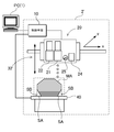
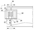
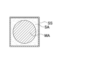
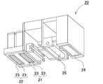
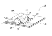
- FIG. 1 is a block diagram showing a three-dimensional modeling apparatus according to a first embodiment. It is a block diagram which shows the three-dimensional modeling apparatus which concerns on a modification. It is a top view which shows a mode that a head part is moved to XY direction. It is a perspective view which shows the modeling thing modeled by model material and a support material. It is sectional drawing of FIG. It is a perspective view which shows the external appearance of a head part. It is a top view which shows a mode that a modeling material is discharged by the head part of FIG. It is a perspective view which shows the state which removes the excess of a modeling material with a roller part.
- the embodiment shown below is an example of a three-dimensional modeling apparatus and a three-dimensional modeling method for embodying the technical idea of the present invention
- the present invention is a three-dimensional modeling apparatus and a three-dimensional modeling method Is not specified as
- the present specification does not in any way specify the members described in the claims to the members of the embodiment.
- the dimensions, materials, shapes, relative arrangements, and the like of the components described in the embodiments are not intended to limit the scope of the present invention to the scope of the present invention unless otherwise specified. It is just an example. Note that the size, positional relationship, and the like of the members shown in each drawing may be exaggerated for the sake of clarity.
- each element constituting the present invention may be configured such that a plurality of elements are constituted by the same member and one member is used in common as a plurality of elements, or conversely, the function of one member is realized by a plurality of members It can be shared and realized.
- connection between the three-dimensional modeling apparatus used in the embodiment of the present invention and a computer, a printer, an external storage device, and other peripheral devices connected thereto for operation, control, display, other processing, etc. RS-232x, RS-422, RS-423, RS-485, serial connection such as USB, parallel connection, or electrical or magnetic via a network such as 10BASE-T, 100BASE-TX, 1000BASE-T, etc. Connect optically and communicate.
- the connection is not limited to physical connection using a wired connection, and wireless connection such as wireless LAN such as IEEE802.1x, radio waves such as Bluetooth (registered trademark), infrared light, optical communication, etc. may be used.
- the three-dimensional modeling apparatus is used to mean not only the three-dimensional modeling apparatus main body but also a three-dimensional modeling system in which peripheral devices such as a computer and an external storage device are combined.
- the three-dimensional modeling apparatus, the three-dimensional modeling method, and the three-dimensional modeling program are a system that performs three-dimensional modeling itself, and hardware for input / output, display, calculation, communication, and other processing related to image generation. It is not limited to the device or method to be performed.
- An apparatus or method for realizing processing in software is also included in the scope of the present invention. For example, software, programs, plug-ins, objects, libraries, applets, compilers, modules, macros operating on a specific program, etc. are incorporated into a general-purpose circuit or computer to enable image generation itself or processing related thereto.
- the apparatus and system also correspond to the three-dimensional modeling apparatus, three-dimensional modeling method, three-dimensional modeling program, and computer readable recording medium of the present invention.
- computers include general-purpose and dedicated electronic computers, as well as workstations, terminals, portable electronic devices, PDC, CDMA, W-CDMA, FOMA (registered trademark), GSM, IMT 2000, fourth-generation etc. It also includes mobile phones, PHSs, PDAs, pagers, smart phones and other electronic devices.
- the program is not limited to one used alone, but may be an aspect that functions as a part of a specific computer program, software, service, etc., an aspect that is called and operated when necessary, It can also be used as an aspect of being provided as a service in an environment, an aspect of operating and resident in an environment, an aspect of operating in the background, and other supporting programs.
- Example 1
- FIG. 1 shows a block diagram of a three-dimensional modeling system 100 according to a first embodiment of the present invention.
- the three-dimensional modeling system 100 manufactures an optional three-dimensional object by discharging and curing a modeling material in a liquid or fluid state by an inkjet method and laminating the same.
- a model material MA constituting a final three-dimensional object
- a support material SA which is at least shaped to support the overhanging portion from which the model material MA overhangs from below in the Z direction and is finally removed Is used.
- a three-dimensional modeling system 100 shown in FIG. 1 includes a setting data creation apparatus 1 (a computer PC in FIG. 1) for transmitting setting data to the three-dimensional modeling apparatus 2 and a three-dimensional modeling apparatus 2.
- the three-dimensional modeling apparatus 2 includes a control unit 10, a head unit 20, and a modeling plate 40.
- the head unit 20 includes a model material discharge nozzle 21 that discharges the model material MA, and a support material discharge nozzle 22 that discharges the support material SA, as a forming material discharge unit.
- the head unit 20 is also provided with a roller unit 25 for smoothing the surface of the forming material by scraping the excess from the discharged forming material, and a curing means 24 for curing the forming material.
- the head portion 20 is reciprocated in the horizontal direction so that the modeling material is ejected from the model material ejection nozzle 21 and the support material ejection nozzle 22 in a liquid or fluid state by an ink jet method to an appropriate position on the modeling plate 40 X and Y directions as horizontal driving means for scanning in the X direction and Y direction orthogonal to the X direction, and as vertical driving means for moving the relative position between the head unit 20 and the shaping plate 40 in the height direction
- the drive unit 31 and the Z direction drive unit 32 are provided.
- the computer PC When the computer PC receives an input of a three-dimensional shaped object, for example, model data designed by three-dimensional CAD, from the outside, it first converts the CAD data to, for example, STL (Stereo Lithography Data) data, and further Setting data creation apparatus 1 which generates cross-sectional data obtained by slicing STL data into a plurality of thin cross-sections, and transmits this slice data to the three-dimensional modeling apparatus 2 collectively or in units of slice layers Act as.
- STL Stepo Lithography Data
- control means 10 takes in sectional data from the computer PC, and controls the head unit 20, the XY direction drive unit 31 and the Z direction drive unit 32 according to the data.
- the XY direction drive unit 31 is operated, and the model material MA and the support material SA as a modeling material are made small droplets from the model material discharge nozzle 21 and the support material discharge nozzle 22 of the head unit 20.
- a cross-sectional shape based on the cross-sectional data supplied from the computer PC is formed.
- the model material MA which is one of the forming materials discharged onto the forming plate 40, is at least cured to change from a liquid or fluid state to a solid and to be cured.
- Such an operation produces a cross section or slice of one layer.
- slice is a lamination unit of the z-direction of a shaped article
- the number of slices is a value obtained by dividing the height by the lamination thickness.
- the minimum settable discharge amount due to the dischargeable minimum unit discharge amount from each discharge nozzle, the deviation due to the eccentricity of the roller portion 25 in the vertical direction, etc. The thickness is determined.
- the user can subsequently determine each slice amount from the viewpoint of the modeling accuracy or the modeling speed, for example, for the modeling object. .
- each slice amount is determined by the above-mentioned slice minimum value or a value in the vicinity thereof, while if priority is given to modeling speed, the minimum modeling accuracy is maintained.
- Each slice amount can be determined.
- a combination of several forming times and forming accuracy is made by allowing the user to intuitively select the ratio of the forming accuracy and the forming velocity, or by letting the user input the maximum forming time that is acceptable. It is also possible to display the candidate as a candidate and select the condition preferred by the user among them.
- the modeling operation for one slice data is performed by using the modeling material in a liquid or fluid state from the model material discharge nozzle 21 and the support material discharge nozzle 22 at least on the outward path or return path when reciprocating the head unit 20 in the X direction.
- the surface of the smoothed shaped article is irradiated with light of a specific wavelength from the curing means 24 to perform at least one series of steps for curing the shaped article. Needless to say, it is automatically changed according to the thickness of slice data and the required forming accuracy.
- the maximum thickness of one time formed on the shaping plate, which is discharged from the model material discharge nozzle 21 and the support material discharge nozzle 22 at least in the forward pass or return pass, is the cross-sectional shape after landing of the discharged droplets. Is determined by the unit discharge amount capable of retaining a substantially circular shape.
- the modeling plate 40 can be raised and lowered by the Z-direction drive unit 32.
- the control means 10 controls the Z-direction driving unit 32, and the shaping plate 40 is lowered by a distance corresponding to the thickness of one slice. Then, by repeating the same operation as described above, a new slice is stacked on the upper side (upper surface) of the first slice. Layers of thin slices continuously produced in this manner are stacked to form a shaped object.
- the control means 10 shapes the overhanging support portion SB based on the shape of the overhanging support portion simultaneously with the formation of the model material MA constituting the final formed article.
- the overhanging support portion SB is formed by discharging the support material SA different from the model material MA as small droplets from the support material discharge nozzle 22.
- the head unit 20 is moved by the head moving means 30 in the horizontal direction, that is, in the XY direction, as shown in the plan view of FIG. Further, as shown in FIG. 1, the shaping plate 40 is moved in the height direction, that is, in the Z direction by the plate lifting means (Z direction drive unit 32). By this, the relative height of head part 20 and modeling plate 40 can be changed, and three-dimensional modeling becomes possible. More specifically, first, the head unit 20 discharges the model material MA as a modeling material and the support material SA from the model material discharge nozzle 21 and the support material discharge nozzle 22 by the head moving means 30 to an appropriate location based on slice data.
- the model material MA and the support material SA are discharged from the plurality of orifices extending in the Y direction which are reciprocated in the X direction and provided in the discharge nozzles 21 and 22 respectively. Furthermore, as shown in FIG. 3, when the width in the Y direction of each discharge nozzle 21, 22 is smaller than the width in the formable Y direction on the forming plate 40, the width in the Y direction of the model data for forming Is larger than the total length of the orifice extending in the Y direction, the ejection nozzles 21 and 22 are shifted in the Y direction by a predetermined amount after reciprocating movement in the X direction at the predetermined positions of the ejection nozzles 21 and 22 By repeating discharging the model material MA and the support material SA to appropriate locations based on slice data along with reciprocating scanning in the X direction, generation of a three-dimensional object corresponding to all set formation data is performed. .
- the plate raising / lowering means which raises / lowers the modeling plate 40 as the Z direction drive part 32 is used, it is not limited to this example, Like three-dimensional modeling device 2 'shown in FIG. It is also possible to adopt a Z-direction drive unit 32 'that fixes the 40 side in the height direction and moves the head side in the Z direction. In addition, also in the movement in the XY direction, the head side may be fixed and the shaping plate side may be moved.
- each orifice becomes an orifice at the time of previous shaping by the shift in the Y direction It may be shifted to be located between the and the orifice.
- the control means 10 controls the discharge pattern of the forming material. That is, the head portion 20 is reciprocally scanned in one direction while discharging the model material MA and the support material SA onto the modeling plate 40 by the modeling material discharging means at least one of the forward pass and the return pass in the reciprocating scan in the X direction.
- the model material MA and the support material SA by the curing means 24 after the modeling material is discharged onto the modeling plate by the modeling material discharge means, and at least one of the forward path and the return path A slice is generated, the relative position of the shaping plate 40 and the head unit 20 is moved in the height direction, and the formation is performed by repeating stacking of the slices.
- the smoothing of the surface of the forming material by the roller unit 25 is performed by curing the surface of the forming material by the curing means 24 after the forming material is discharged onto the forming plate by the forming material discharging means. It is carried out in at least one of the forward pass and the return pass before making it go.
- the control means 10 discharges either one of the modeling material MA or the support material SA in a single reciprocating scan, smoothes the surface of the modeling material by the roller portion 25, and further cures it by the curing means 24. Then, in the next and subsequent reciprocating scanning, the other modeling material that has not been discharged is discharged to smooth and harden the surface of the modeling material.
- One slice is generated by performing the series of steps at least once. Needless to say, the above-described series of processes corresponding to slice data of one layer is repeated a plurality of times depending on, for example, the surface accuracy and modeling time of the final model that the user desires.
- the surface of the model material MA or the support material SA is smoothed in the uncured state and then cured, and then can be cured separately by discharging the other, and these model material MA and the support material
- the advantage is obtained that the mixing at the interface of SA can be effectively avoided.
- FIG. 4 shows a perspective view of a shaped object formed by covering the periphery of a spherical model material MA with a rectangular parallelepiped support material SA
- FIG. 5 shows this cross-sectional view, respectively.
- a photocurable resin such as an ultraviolet curable resin
- the curing means 24 is a light emitting means for emitting light containing a specific wavelength at which the material of the model material MA reacts and cures, and is, for example, an ultraviolet ray emitting means such as an ultraviolet lamp.
- an ultraviolet ray emitting means such as an ultraviolet lamp.
- a halogen lamp, a mercury lamp, an LED or the like can be used as the ultraviolet light lamp.
- the support material is also an ultraviolet curable resin.
- the same ultraviolet irradiation means can be used, and the advantage that the light source can be made common can be obtained.
- thermoplastic resin can also be used as a model material.
- the curing means 24 is a cooling means.
- thermoplastic resin is used for both the model material and the support material, by using a material whose melting point is higher than that of the support material, the shaped object is made higher than the melting point of the support material after lamination is completed, The support material can be melted and removed by heating and keeping the temperature lower than the melting point of the model material.
- one of the model material and the support material may be a photocurable resin, and the other may be a thermoplastic resin.
- model material a material that can be cured by a chemical reaction with the curing material can be used as a model material.
- the model material may be mixed with a liquid modifier as needed in order to adjust the ejection characteristics such as viscosity and surface tension. The injection characteristics can also be changed by temperature control.
- model materials include ultraviolet photopolymers, epoxy resins, acrylic resins, urethanes and the like.
- the support material SA water-swellable gel, wax, thermoplastic resin, water-soluble material, soluble material and the like can be used as a removable material.
- methods such as separation using a thermal expansion difference or the like can be appropriately used, which is dissolved by power washing such as water, heating, chemical reaction, hydraulic washing or irradiation with electromagnetic waves depending on the properties of the support material. .
- the water-soluble support material can be removed by melting the support material by putting it into a water tank after the shaped article is formed.
- the solubility of the support material is increased, the strength of the support material decreases, and when the humidity is high, the support material deliquesces, and it is likely to be deformed or dropped. If the rigidity of the support material is insufficient, the ability to support the model material is reduced, it may be difficult to form the model material on the upper surface of the support material, and the accuracy of the model material may be reduced.
- the support material when using a water-soluble material, for example, as the support material, the support material is directly formed during modeling of the model in the modeling apparatus by forming the support shell SS as the outer shell of the support material SA.
- Contact with air can be suppressed as much as possible, and as a result, the support material can be prevented from absorbing moisture in the air, whereby deformation of the model material due to deformation of the support material or deformation of the support material can be prevented during modeling.
- the formation of the support shell SS can suppress the internal support material from absorbing the moisture in the air, thereby enhancing the water-soluble performance of the support material. As a result, when removing the support material, etc.
- the dissolution rate of the support material when immersed in the solution of With this configuration, it is possible to obtain an advantage that the dissolution can be accelerated by breaking the outermost support material SA at the time of removal while having sufficient rigidity, and the support material can be removed in a short time.
- the support shell SS coated on the rectangular surface is broken to remove the inner support material SA.
- the support material SA contains a non-hardening component.
- the support material can be eluted and removed in a short time by being introduced into a water tank.
- the solubility of the support material is not limited to water solubility, and may be soluble in a specific solvent.
- the support shell SS is provided on the surface of the support material for protection.
- the support shell SS provided on the outer surface of the support material SA is made of a model material MA that is more rigid than the support material SA. In this manner, the rigidity of the surface of the support material SA can be increased, and the outflow of the support material SA can be prevented.
- the support shell SS is made of the model material MA discharged from the model material discharge nozzle 21, the model material discharge nozzle 21 of the head unit 20 can be shared as the discharge nozzle of the support shell SS. Since the support shell SS of the support material SA can also be formed at the time of formation of the material MA, it is advantageous in cost and speed.
- model data MA and support material SA generate three-dimensional modeling data
- the modeling data is automatically generated with respect to the position at which the outer surface of the modeling data is formed by the support material
- the support material located on the outer surface thereof is changed to a model material, or data is generated to form a thin film layer formed of the model material so as to cover the outer surface of the support material.
- the model material MA is discharged and hardened, and the outer surface of the support material SA is thin.
- the control means 10 controls the modeling material discharge means so as to be covered with the model material MA.
- the support shell SS is configured by the model material MA discharged from the model material discharge nozzle 21.
- a material different from the model material MA is discharged It is also possible to separately provide a nozzle for forming the support shell.
- this support shell is a material which has hardness and lower toughness than model material MA from the viewpoint of balancing the ease of removal and securing of strength in higher dimensions. Is preferred. (Peeling structure of support shell SS)
- the support shell SS is provided in the support material SA
- the higher the rigidity of the support shell SS the more difficult it is to peel the support shell SS from the modeling material. Therefore, it is preferable to add a structure that facilitates peeling of the support shell SS.
- the entire surface of the support material SA is not covered with the support shell SS, but an exposed portion in which the support material SA is partially exposed is provided. By doing so, the support shell SS is likely to be broken at the exposed portion after shaping of the shaped article.
- the support material SA when the support material SA is made soluble, it can be impregnated in a liquid after formation of a shaped object to elute the support material SA from the exposed portion, and can be peeled from the shaped object without breaking the support shell SS, There is an advantage that labor for removing the material SA can be saved.
- the support shell SS can be formed by making the outer peripheral portion of the continuous outer surface where the support shell SS has to be formed thicker than the other outer surfaces on which the support shell SS is formed. It is also possible to make it easy to peel off integrally the continuous outer surface formed. (Head unit 20)
- FIG. 1 An example of the head part 20 of the three-dimensional modeling apparatus of an inkjet system is shown in FIG.
- the head unit 20 shown in this figure is provided with a dedicated discharge nozzle that discharges the model material MA and the support material SA individually as a forming material discharge means.
- the model material discharge nozzle 21 for discharging the model material MA and the support material discharge nozzle 22 for discharging the support material SA are provided in parallel and separated.
- Each discharge nozzle is provided with two nozzle rows 23, and the nozzle rows 23 are arranged by being shifted by a half nozzle as shown in the plan view of FIG. 7 to improve the resolution.
- the nozzle rows 23 arranged in the offset state are arranged to coincide with each other on the same line by the model material discharge nozzle 21 and the support material discharge nozzle 22, respectively, thereby matching the resolutions of the model material and the support material I am doing it.
- each discharge nozzle discharges an ink-like modeling material in the manner of a piezoelectric element type inkjet print head. Moreover, the modeling material is adjusted to the viscosity which can be discharged from a discharge nozzle.
- the support material SA is discharged.
- the head portion 20 discharges the forming material in the forward path (left to right in the figure), and in the return path (right to left in the figure), it is cured by the curing means 24. (Roller unit 25)
- the head unit 20 further presses the surface of the discharged model material MA and support material SA in a non-cured state, and removes excess portions of the modeling material to smooth the surface of the modeling material 25.
- the operation of the roller unit 25 will be described based on the schematic view of FIG. In this example, a state in which the surface of the discharged model material MA is leveled by the roller body 26 in an uncured state is shown.
- the roller unit 25 includes a roller body 26 which is a rotating body, a blade 27 disposed to protrude from the surface of the roller body 26, a bus 28 for storing the forming material scraped off by the blade 27, and a bus 28. And a suction pipe 29 for discharging the accumulated build material.
- the roller body 26 is rotated in the reverse direction (clockwise in FIG. 8) with respect to the direction in which the head unit 20 moves, and scrapes the uncured modeling material.
- the scraped building material adheres to the roller body 26 and is conveyed to the blade 27, and then scraped off by the blade 27 and guided to the bath 28.
- the blade 27 is fixed in a downhill posture toward the bus 28.
- the suction pipe 29 is connected to a pump and sucks and discharges the build material accumulated in the bath 28.
- the outer diameter of the roller body 26 is about ⁇ 20 mm, and the rotational speed is about 10 rotations / s.
- the roller unit 25 scrapes when the head unit 20 advances from right to left in the drawing. In other words, when the model material MA and the support material SA are respectively discharged from the model material discharge nozzle 21 and the support material discharge nozzle 22 to appropriate positions based on slice data while the head unit 20 advances from left to right.
- the roller unit 25 does not contact the forming material, and similarly, the illumination from the light source of the curing means 24 is not performed.
- the roller portion 25 is disposed in front of the curing means 24 in the direction of travel of the head portion 20, ie, on the left side in the figure.
- the curing means 24 cures the modeling material.
- Such an arrangement provides the advantage that scraping and curing of the build material can be performed in the same pass, and efficient processing can be achieved. (Individual curing at the interface)
- the model material MA and the support material SA are separately cured in order to avoid mixing of the two at the boundary between the model material MA and the support material SA. Therefore, the control means 10 sets discharge patterns of the model material MA and the support material SA.
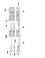
- this procedure will be described based on a plan view and a vertical cross-sectional view showing the discharge pattern of FIGS.
- FIGS. In these drawings, an example in which one model material MA and support material SA are discharged by one reciprocating scan is described for the sake of explanation. Further, the model material MA is indicated by oblique lines, and the support material SA is indicated by plain. Furthermore, the order of the reciprocation scan is displayed numerically.
- the model material MA and the support material are discharged in the same reciprocating scan. Therefore, two lines can be formed by two reciprocating scans.
- the boundary portion between the model material MA and the support material SA is in contact in an uncured state, and there is a problem that these are mixed at the interface and the quality of the interface is lowered.
- any one of them in the example shown in FIG. 10A, discharges and cures only the model material MA, and discharges the support material SA. do not do. Then, only the support material SA is discharged and cured by another reciprocating scan. As described above, the model material MA and the support material SA are not discharged and cured in the same reciprocating scan, but the model material MA and the support material SA are respectively discharged and cured in separate reciprocating scans, thereby the uncured model material MA It is possible to avoid a situation in which the support member SA contacts with the support member SA.
- At least one forward pass or return path for discharging the model material MA when the model material MA is not cured is smoothed by scraping off excess material by the roller part 25 provided on the head part 20 and has a second thickness thinner than the first thickness described above. And is discharged onto the shaping plate 40 by the curing means 24 in at least one forward pass or return pass same as the smoothing operation by the roller unit 25 or at least one forward pass or return pass after the smoothing operation by the roller unit 25. Cure the model material MA.
- the support material SA is then discharged with a third predetermined thickness thicker than the second predetermined thickness of the model material described above, and then the support material SA In the uncured state, the roller portion 25 provided in the head portion 20 scrapes off excess material in at least one forward pass or return pass different from at least one forward pass or return pass for discharging the support material SA.
- the second material to be discharged later is applied so as to form a third thickness thicker than the second thickness which is the thickness after forming and curing by the roller portion 25 of the first material to be discharged first, Furthermore, by making the fourth thickness, which is the thickness of the second material formed by the roller portion 25 and cured, thicker than or substantially equal to the second thickness and thinner than the third thickness.
- the first and second materials that is, the interface between the model material MA and the support material SA can be prevented from mixing with each other, and the surface of any of the materials can be smoothed.
- the support material SA is discharged and formed following the line of the model material MA formed in the second reciprocating scan.
- the modeling material is sufficiently cured to mix at the interface that contacts Can be reliably blocked.
- it is effective when using a resin or the like having a slow curing reaction as the model material MA or the support material SA.
- the above-described series of forming steps of the model material MA and the support material SA may be all steps based on one slice data, or may be steps constituting part thereof, or a part of them. In the case of the above, the above-described series of molding steps will be repeated as necessary. (Example 2)
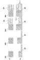
- FIG. 10 While the method of FIG. 10 can reliably prevent the mixing with another forming material by curing one of the forming materials, it requires two reciprocating scans to form one line as compared with the method of FIG. Therefore, the tact time is doubled. Therefore, an example for avoiding this problem will be described as a second embodiment based on FIG.
- FIG. 10 it is the same as FIG. 10 in that two model materials MA are formed in the first and second reciprocating scanning.
- the model material MA is discharged and cured between the first model material MA and the second model material MA.
- the model material MA is formed below the second model material MA. After molding four model materials MA in this manner, the support material SA is continuously discharged and cured by the fifth and sixth reciprocating scanning.
- each support material SA is twice that of FIG.
- the support material SA of 30 ⁇ m twice as large as that is discharged and cured in FIG.
- the support material SA can form an amount corresponding to four reciprocating scans of the model material even with two reciprocating scans.
- shaping equivalent to that of four reciprocations of FIG. 9, that is, four reciprocations becomes possible. It requires twice the tact time. As described above, it is possible to suppress the doubled tact time in FIG.
- the resolution of the support material SA is reduced to half compared to FIG.
- the support material SA is finally removed, it does not degrade the quality of the obtained shaped object.
- the model material M After discharging A at a first predetermined thickness, in the uncured state of the model material MA, at least one forward pass for discharging the model material MA or at least one forward pass or return pass different from the return pass to the head portion 20
- the model material MA is smoothed by scraping off excess material by the provided roller portion 25 and has a second thickness thinner than the above-described first thickness, and is the same as the operation of smoothing by the roller portion 25.
- the curing of the model material MA discharged onto the shaping plate 40 by the curing means 24 is performed.
- the model material MA After discharging the model material MA with a third predetermined thickness on at least a part of the surface of the model material MA molded into the second thickness, to an appropriate position based on slice data in practice, In the uncured state of the model material MA, scraping off excess material by the roller portion 25 provided in the head portion 20 in at least one outward path or return path different from at least one outward path or discharge path for discharging the model material MA , And secures the model material MA having the fourth thickness thinner than the third thickness described above, and at least one forward pass or return pass, which is the same as the smoothing operation by the roller unit 25, or The curing of the model material MA discharged onto the shaping plate 40 by the curing means 24 is performed at least one forward pass or return pass after the operation of Thus, at this point in time, the model material has a fifth thickness obtained by adding the fourth thickness to the second thickness as a total by molding twice.
- the support material SA is then discharged with a sixth predetermined thickness thicker than the fifth predetermined thickness of the model material described above, and then the support material SA In the uncured state, the roller portion 25 provided in the head portion 20 scrapes off excess material in at least one forward pass or return pass different from at least one forward pass or return pass for discharging the support material SA.
- the support material SA having a seventh thickness which is thicker than or substantially equal to the fifth thickness of the model material described above and which is thinner than the sixth thickness of the support material SA;
- the curing means 24 in at least one forward pass or return pass identical to the smoothing action by No. 25 or at least one forward pass or return path after the smooth action by the roller unit 25 Ri effect curing of the support member SA which is discharged onto the shaping plate 40.
- the sixth thickness is formed so as to form a sixth thickness thicker than the fifth thickness which is the thickness after forming and curing by the roller portion 25 of the first material to be discharged.
- a second material to be discharged is applied, and a seventh thickness which is a thickness of the second material after molding and curing by the roller portion 25 is thicker than or substantially equal to the fifth thickness, And, by making the thickness smaller than the seventh thickness, it is possible to prevent the mixing of the other materials at the interface where the first and second materials, ie, the model material MA and the support material SA contact each other, Smoothing can also be performed.
- the third and fourth modeling of the model material MA is between the first and second times in the example of FIG. 11A, and in the example of FIG.
- the second interval is shown in FIG. 11 (a)
- the spacing on the line in the plane is large, but in fact, as a result, the modeling material is ejected as a larger droplet, as shown in FIG. It is because it is laminated
- FIG. 12 an example in which the tact time is improved from the second embodiment is shown in FIG. 12 as a third embodiment.
- the procedure of the reciprocal scanning is the same as in FIG. 11, but the discharge amount of the forming material is changed.
- the discharge amount of the model material MA is 1.5 times that of FIG. 11 (FIG. 10).
- the formation height of the model material MA is 15 ⁇ m in FIG. 11B, it is 22.5 ⁇ m that is 1.5 times that in FIG.
- the discharge amount of the support material SA is 1.5 times (three times that of FIG. 10) that of FIG.
- the forming material can be stacked up to a total height of 45 ⁇ m by six reciprocal scanning.
- FIG. 10 the procedure of the reciprocal scanning is the same as in FIG. 11, but the discharge amount of the forming material is changed.
- the discharge amount of the model material MA is 1.5 times that of FIG. 11 (FIG. 10).
- the formation height of the model material MA is 15 ⁇ m in FIG. 11B
- it is 22.5
- the first ejection is performed on the same line as the model material MA, and is cured in the return path.
- the support material SA is subsequently placed on the same line as the offset position, in the example of FIG. Discharge and cure in the return path.
- the support material SA is discharged and cured on the same line as the third and fourth model materials MA in the subsequent fifth and sixth reciprocal scanning.
- the uncured model material MA and the support material SA are cured together in the return path at the time of the third and fourth reciprocating scans, otherwise there is a possibility of mixing because both are uncured at this stage.
- At least one forward pass or return path for discharging the model material MA when the model material MA is not cured is smoothed by scraping off excess material by the roller part 25 provided on the head part 20 and has a second thickness thinner than the first thickness described above. And is discharged onto the shaping plate 40 by the curing means 24 in at least one forward pass or return pass same as the smoothing operation by the roller unit 25 or at least one forward pass or return pass after the smoothing operation by the roller unit 25. Cure the model material MA.
- the model material MA After discharging the model material MA with a third predetermined thickness on at least a part of the surface of the model material MA molded into the second thickness, to an appropriate position based on slice data in practice, In the uncured state of the model material MA, scraping off excess material by the roller portion 25 provided in the head portion 20 in at least one outward path or return path different from at least one outward path or discharge path for discharging the model material MA , And secures the model material MA having the fourth thickness thinner than the third thickness described above, and at least one forward pass or return pass, which is the same as the smoothing operation by the roller unit 25, or The curing of the model material MA discharged onto the shaping plate 40 by the curing means 24 is performed at least one forward pass or return pass after the operation of Thus, at this point in time, the model material has a fifth thickness obtained by adding the fourth thickness to the second thickness as a total by molding twice.
- the support material SA is formed with a sixth thickness thinner than the fifth thickness of the model material. Discharge to the proper position.
- the sixth thickness of the support material is thinner than the fifth thickness of the model material MA, it is difficult to smooth the surface of the support material by the roller portion 25, Smoothing is performed by the roller unit 25 only on the surface of the model material MA on which the third thickness is formed, and thereafter, the curing process is performed on the surfaces of the model material MA and the support material SA by the curing means 24.
- the support material SA for forming the seventh thickness is further discharged onto the surface of the support material SA having the sixth thickness, and the discharge of the support material SA is performed in the uncured state of the support material SA.
- the fifth portion of the model material described above is smoothed by scraping off excess material by the roller portion 25 provided in the head portion 20 in at least one forward path or return path different from at least one forward path or return path.
- a support material SA having an eighth thickness which is thicker than or substantially equal to the thickness and thinner than the seventh thickness of the support material SA is secured, and at least one forward pass identical to the smoothing operation by the roller portion 25 Or, at least one forward pass or return pass after the operation of smoothing by the roller section 25 or the return path, the discharging means is discharged onto the shaping plate 40 by the curing means 24. Effect curing of the support member SA being. (Example 5)
- Example 5 the example which improved tact time from Example 4 is demonstrated as Example 5 based on FIG.
- the support material SA On the same line as the first model material MA in the example of FIG. 14A, and after the discharge of the model material MA in the forward pass of the fourth reciprocating scan, the second time The same points as the model material MA are discharged and cured in the return path.
- the discharge amount of the support material SA is doubled as in FIG.
- At least one forward pass or return path for discharging the model material MA when the model material MA is not cured is smoothed by scraping off excess material by the roller part 25 provided on the head part 20 and has a second thickness thinner than the first thickness described above. And is discharged onto the shaping plate 40 by the curing means 24 in at least one forward pass or return pass same as the smoothing operation by the roller unit 25 or at least one forward pass or return pass after the smoothing operation by the roller unit 25. Cure the model material MA.
- the model material MA After discharging the model material MA with a third predetermined thickness on at least a part of the surface of the model material MA molded into the second thickness, to an appropriate position based on slice data in practice, In the uncured state of the model material MA, scraping off excess material by the roller portion 25 provided in the head portion 20 in at least one outward path or return path different from at least one outward path or discharge path for discharging the model material MA , And secures the model material MA having the fourth thickness thinner than the third thickness described above, and at least one forward pass or return pass, which is the same as the smoothing operation by the roller unit 25, or The curing of the model material MA discharged onto the shaping plate 40 by the curing means 24 is performed at least one forward pass or return pass after the operation of Thus, at this point in time, the model material has a fifth thickness obtained by adding the fourth thickness to the second thickness as a total by molding twice.
- the support material SA is then provided in the same step in which the application for forming the third thickness with the model material MA is performed next.
- the third thickness surface of the model material MA and the third of the support material SA In the process of smoothing by the roller portion 25 in which the third thickness of the model material MA is the fourth thickness in a state in which the surface of the six thickness is uncured, the second thickness of the model material MA as a total is The extra material is scraped off so as to have a seventh thickness substantially equal to the fifth thickness including the fourth thickness, and further, on the surface of the fifth thickness of the model material MA In the same process as the curing process by the above-mentioned curing means performed for Hardening treatment to the surface of the support member SA with seven of thickness is performed. (Example 6)
- Example 5 since the model material MA and the support material SA are adjacent to each other in the height direction as shown in FIG. 14B, there is a problem that mixing in this portion is difficult to avoid. Therefore, an example in which the mixing is reduced by further separating these in the height direction will be described as a sixth embodiment based on FIG.
- the point in which the model material MA is shaped sequentially in the first to fourth reciprocating scanning is the same as FIG. Further, in FIG. 15, the model material MA is discharged on the same line as the first even in the fifth reciprocating scan, and the model material MA is discharged on the same line as the second even in the subsequent sixth reciprocating scan. .
- FIG. 15 As a result, as shown in FIG.
- the height of the model material MA is 45 ⁇ m for three slices.
- the model material MA is discharged on the same line as the third, and subsequently, the support material SA is also discharged twice as much on the same line as the fifth model material MA.
- the height of the discharged uncured model material MA is about 60 ⁇ m for four slices, and it is 30 ⁇ m even when the double supporting material SA is discharged, and the uncured model material MA and the supporting material SA Because the height difference is large, the mixing at the interface between the two is reduced.
- the support material SA is discharged twice on the same line as the model material MA following the model material MA.
- the support material SA and the model material MA are both cured in the return path in the seventh and eighth reciprocating scans, the excess support material SA can not be scraped off by the roller portion 25.
- the modeling heights of the model material MA and the support material SA are different. Therefore, in accordance with the model material MA, only the model material MA is scraped off by the roller unit 25. That is, when the roller unit 25 passes the support material SA, the control unit 10 controls the rotation of the roller unit 25 so as to stop the rotation of the roller unit 25. Since the support material SA is finally removed, even if the surface is somewhat rough, there is no problem in the quality of the shaped material.
- the forming time is 15 ⁇ m in FIG. 9 by two reciprocating scans, whereas in FIG. 15 it is 60 ⁇ m in ten reciprocating scans, so the tact time is 1.25 times, Further, the resolution of the support material SA is 1 ⁇ 2.
- the present example is basically the same as Example 4 described above, and the series of discharge, smoothing and curing operations of the same material are repeated several times (four times in the example), and the last four
- a series of operations for discharging and curing the other material is performed (here, the height of the layer formed is lower than the height formed of the previously discharged material, The smoothing process can not be introduced).
- the height higher than the height formed by the material discharged earlier is secured, and the surface is finally discharged by smoothing.
- a curing process by the curing means 24 is performed while securing a height substantially the same as the height formed by the material.
- the three-dimensional modeling apparatus and the three-dimensional modeling method of the present invention can be suitably used for three-dimensional modeling in which an ultraviolet curable resin is laminated by an inkjet method.
- Three-dimensional modeling system 1 Setting data generation apparatus 2
- Three-dimensional modeling apparatus 10 Control means 20: Head section 21: Model material discharge nozzle 22: Support material discharge nozzle 23: Nozzle row 24: Curing means 25 ... Roller portion 26 ... Roller body 27 ... Blade 28 ... Bus 29 ... Suction pipe 30 ... Head moving means 31 ... XY direction drive unit 32, 32 '... Z direction drive unit 40 ... Modeling plate MA ... Model material SA ... Support material SS ... support shell PC ... computer SB ... overhang support
Landscapes
- Engineering & Computer Science (AREA)
- Chemical & Material Sciences (AREA)
- Materials Engineering (AREA)
- Mechanical Engineering (AREA)
- Physics & Mathematics (AREA)
- Manufacturing & Machinery (AREA)
- Optics & Photonics (AREA)
- Robotics (AREA)
Abstract
【課題】モデル材とサポート材の界面での混合を回避する。【解決手段】制御手段が、水平駆動手段でヘッド部20を一方向に往復走査させて、造形材吐出手段によりモデル材MA及びサポート材SAを造形プレート40上に吐出させ、該往復走査の往路又は復路の少なくともいずれか一方で、硬化手段24でモデル材MA及び/又はサポート材SAを硬化させることにより、スライスを生成し、高さ方向に造形プレート40とヘッド部20の相対位置を移動させて、スライスの積層を繰り返すことにより造形を実行するよう制御し、かつ造形物の走査方向におけるモデル材MAとサポート材SAとが位置するラインにおいて、同一の往復走査で、モデル材MAとサポート材SAを同時に吐出させず、いずれか一方の造形材のみを吐出、硬化させてなることができる。
Description
本発明は、インクジェット方式で立体造形物を作製する三次元造形装置及び三次元造形方法に関する。
従来より、造形物を平行な複数の面で切断した各断面毎に樹脂を順次積層することよって立体造形を行い、造形物の三次元モデルとなる造形物を生成する装置が知られている。
製品開発において試作等に用いられるラピッド・プロトタイピング(Rapid Prototyping:RP)の分野で、三次元造型が可能な積層造形法が利用されている。積層造形法としては、積層造形法は、製品の三次元CADデータをスライスし、薄板を重ね合わせたようなものを製造の元データとして作成し、それに粉体、樹脂、鋼板、紙等の材料を積層して試作品を作成する。このような積層造形法としては、インクジェット法、粉末法、光造形法、シート積層法、押し出し法等が知られている。この内、インクジェット法は、液化した材料を噴射した後、紫外光(UV)を照射したり、冷却する等によって層を硬化させて形成する。この方法によれば、インクジェットプリンタの原理を応用できることから、高精細化が容易となる利点が得られる。
樹脂積層方式の三次元造形装置は、最終的な造形物となるモデル材と、モデル材の張り出し部分を支え、最終的に除去されるサポート材をXY方向に走査しながら造形プレート上に吐出し、高さ方向に積層していくことにより、造形を行う。モデル材とサポート材は紫外光を照射することにより、硬化する特性を有する樹脂からなり、紫外光を照射する紫外光ランプはモデル材とサポート材を吐出するノズルと共に、XY方向に走査され、ノズルから吐出されたモデル材およびサポート材に紫外光を照射し、硬化させる。
しかしながら、従来は図9(a)の平面図に示すように、一回の走査(X方向)でモデル材MAとサポート材SAとが同時に吐出され、未硬化状態でモデル材MAとサポート材SAが接触するため、モデル材MAとサポート材SAの境界部においては、図9(b)の垂直断面図に示すように両材料が未硬化の液体状態で混ざり合ってしまうという問題があった。この状態で硬化すると、その混合部が膨張、変色を生じて造形品質を低下させる。また、サポート材の除去も困難となる。さらに、一般に紫外光ランプはノズルと共に走査される構造であるため、モデル材とサポート材がノズルから吐出された直後に硬化させるのは困難である。このため、未硬化の状態で混ざり合った状態が長く続けば続くほど、上述した問題は顕著となっていた。
本発明は、従来のこのような問題点に鑑みてなされたものであり、その主な目的は、モデル材とサポート材の界面での混合を回避した三次元造形装置及び三次元造形方法を提供することにある。
上記の目的を達成するために、本発明の第1の側面に係る三次元造形装置によれば、造形プレート40上に、造形材として、最終的な造形物となるモデル材MAと、前記モデル材MAが張り出した張り出し部分を支え、最終的に除去されるサポート材SAと、を少なくとも一方向に走査しながら吐出させ、かつこれを硬化させる動作を繰り返すことで、高さ方向に所定の厚みを有するスライスを生成し、該スライスを高さ方向に積層していくことにより造形を行う三次元造形装置であって、造形物を載置するための前記造形プレート40と、前記モデル材MAを吐出するためのモデル材吐出ノズル21、及び前記サポート材SAを吐出するためのサポート材吐出ノズル22を、それぞれ一方向に複数個配列させた造形材吐出手段と、前記モデル材MA及びサポート材SAを硬化させるための硬化手段24と、前記造形材吐出手段及び硬化手段24を備えるヘッド部20と、前記ヘッド部20を水平方向に往復走査させるための水平駆動手段と、前記ヘッド部20と造形プレート40との高さ方向の相対位置を移動させるための垂直駆動手段と、前記水平駆動手段及び垂直駆動手段の駆動を制御し、かつ前記造形材吐出手段による前記造形材による吐出及び硬化手段24による硬化を制御する制御手段と、を備え、前記制御手段が、前記水平駆動手段で前記ヘッド部20を一方向に往復走査させて、前記造形材吐出手段により前記モデル材MA及びサポート材SAを前記造形プレート40上に吐出させ、該往復走査の往路又は復路の少なくともいずれか一方で、前記硬化手段24で前記モデル材MA及び/又はサポート材SAを硬化させることにより、前記スライスを生成し、高さ方向に前記造形プレート40とヘッド部20の相対位置を移動させて、前記スライスの積層を繰り返すことにより造形を実行するよう制御し、かつ造形物の走査方向における前記モデル材MAとサポート材SAとが位置するラインにおいて、同一の往復走査で、前記モデル材MAとサポート材SAを同時に吐出させず、いずれか一方の造形材のみを吐出、硬化させてなることができる。これにより、同一の往復走査で、モデル材とサポート材を同時に吐出せず、いずれか一方のみを吐出、硬化させることで、同一ライン上で隣接するモデル材とサポート材との界面が共に未硬化となって混合する事態を回避でき、界面を綺麗に成形できる利点が得られる。
また、第2の側面に係る三次元造形装置によれば、前記ヘッド部20の一回の往復走査で吐出、硬化された前記モデル材MA又はサポート材SAのいずれか一方の造形材と、同一ライン上に形成される他方の造形材は、次回以降の往復走査で吐出、硬化させることができる。これにより、二回の走査で一回分の造形材を塗布できる。
さらに、第3の側面に係る三次元造形装置によれば、前記ヘッド部20が、前記モデル材MA又はサポート材SAのいずれか一方の造形材を、連続する往復走査で吐出、硬化を形成した後、他方の造形材を、次回の往復走査で、吐出、硬化できる。これにより、モデル材とサポート材を交互に吐出、硬化するのでなく、一方の造形材を連続して成形することで、他方の造形材が吐出されるまでの時間を置くことができ、より確実な硬化が見込まれ、界面での混合をより確実に回避できる利点が得られる。
さらにまた、第4の側面に係る三次元造形装置によれば、前記造形材吐出手段が、一回の往復走査の内、往路で吐出を行い、前記硬化手段24が、一回の往復走査の内、復路で硬化を行うことができる。これにより、一回の往復走査で、造形材の吐出と硬化を行うことができる。
さらにまた、第5の側面に係る三次元造形装置によれば、さらに前記造形プレート40上に吐出された造形材を未硬化の状態で押圧するためのローラ部25を備えることができる。これにより、造形材の表面を硬化前に均一に均して品質を向上できる。また造形材の余剰分を排除することもできる。
さらにまた、第6の側面に係る三次元造形装置によれば、前記ローラ部25が、硬化されたモデル材MAと未硬化のサポート材SAとを含むスライスに対して走査するよう構成されており、該未硬化のサポート材SAが、硬化されたモデル材MAよりも所定のオフセット量分高くなるように前記造形材吐出手段から吐出することができる。このように、未硬化のサポート材を硬化済みのモデル材よりも高くすることで、ローラ部がサポート材によって押し上げられる結果、硬化済みのモデル材にローラ部が触れる事態が回避され、よって硬化済みのモデル材が削られてローラ部に不具合を生じる事態を回避できる。
さらにまた、第7の側面に係る三次元造形装置によれば、前記所定のオフセット量を、前記ローラ部25の高さ方向における位置ずれの分布を考慮して設定することができる。このように、ローラ部の誤差、例えば真円度からのずれや偏心、固定位置のばらつき等を勘案したオフセット量を設定することで、ローラ部が硬化済みのモデル材に接触しないサポート材の高さを適切に設定できる。
さらにまた、第8の側面に係る三次元造形装置によれば、前記造形プレート40上に逐次形成されるスライスのXY平面の各位置において、最下段に位置するサポート材SAに対して、前記オフセット量分が加算されて前記造形材吐出手段から吐出させることができる。これにより、最下段に位置するサポート材を高くすることで、以降この上に積層されるサポート材等はすべて、オフセット量分高くなるため、上述の通りローラ部が硬化済みのモデル材に接触する事態を回避できる。
さらにまた、第9の側面に係る三次元造形装置によれば、前記モデル材MAが、光硬化樹脂であり、前記硬化手段24は、光を照射するための光照射手段とできる。これにより、モデル材を光で容易に硬化させることができる。このような光には紫外光等が好適に利用できる。
さらにまた、第10の側面に係る三次元造形装置によれば、前記造形材吐出手段は、前記モデル材MAと前記サポート材SAとを離間させて吐出することができる。これにより、モデル材とサポート材との界面での混合を確実に回避できる。
さらにまた、第11の側面に係る三次元造形方法によれば、造形物を載置するための造形プレート40上に、造形材として、最終的な造形物となるモデル材MAと、前記モデル材MAが張り出した張り出し部分を支え、最終的に除去されるサポート材SAと、を少なくとも一方向に走査しながら吐出させ、かつこれを硬化させる動作を繰り返すことで、高さ方向に所定の厚みを有するスライスを生成し、該スライスを高さ方向に積層していくことにより造形を行う三次元造形方法であって、前記モデル材MA又はサポート材SAのいずれか一方の造形材を、該造形材を吐出するための造形材吐出手段により前記造形プレート40上に吐出させる工程と、該吐出された一方の造形材を、該造形材を硬化させる硬化手段24で硬化させる工程と、前記モデル材MA又はサポート材SAのいずれか吐出されなかった他方の造形材を、前記造形材吐出手段により前記造形プレート40上に吐出させる工程と、該他方の造形材を、前記硬化手段24で硬化させる工程と、前記硬化されたモデル材MA又はサポート材SAによって前記スライスを生成すると、高さ方向に前記造形プレート40とヘッド部20の相対位置を移動させて、前記スライスの積層を繰り返す工程と、を含むことができる。これにより、モデル材又はサポート材のいずれか一方の硬化させた後、他方を吐出することで個別に硬化でき、これらモデル材とサポート材の界面における混合を効果的に回避できる利点が得られる。
さらにまた、第12の側面に係る三次元造形プログラムによれば、造形物を載置するための造形プレート40上に、造形材として、最終的な造形物となるモデル材MAと、前記モデル材MAが張り出した張り出し部分を支え、最終的に除去されるサポート材SAと、を少なくとも一方向に走査しながら吐出させ、かつこれを硬化させる動作を繰り返すことで、高さ方向に所定の厚みを有するスライスを生成し、該スライスを高さ方向に積層していくことにより造形を行う三次元造形プログラムであって、前記モデル材MA又はサポート材SAのいずれか一方の造形材を、該造形材を吐出するための造形材吐出手段により前記造形プレート40上に吐出させる機能と、該吐出された一方の造形材を、該造形材を硬化させる硬化手段24で硬化させる機能と、前記モデル材MA又はサポート材SAのいずれか吐出されなかった他方の造形材を、前記造形材吐出手段により前記造形プレート40上に吐出させる機能と、該他方の造形材を、前記硬化手段24で硬化させる機能と、前記硬化されたモデル材MA又はサポート材SAによって前記スライスを生成すると、高さ方向に前記造形プレート40とヘッド部20の相対位置を移動させて、前記スライスの積層を繰り返す機能と、をコンピュータに実現させることができる。これにより、モデル材又はサポート材のい
ずれか一方の硬化させた後、他方を吐出することで個別に硬化でき、これらモデル材とサポート材の界面における混合を効果的に回避できる利点が得られる。
ずれか一方の硬化させた後、他方を吐出することで個別に硬化でき、これらモデル材とサポート材の界面における混合を効果的に回避できる利点が得られる。
さらにまた第13の側面に係るコンピュータで読み取り可能な記録媒体は、前記プログラムを格納したものである。記録媒体には、CD-ROM、CD-R、CD-RWやフレキシブルディスク、磁気テープ、MO、DVD-ROM、DVD-RAM、DVD-R、DVD+R、DVD-RW、DVD+RW、Blu-ray、HD DVD(AOD)等の磁気ディスク、光ディスク、光磁気ディスク、半導体メモリその他のプログラムを格納可能な媒体が含まれる。またプログラムには、前記記録媒体に格納されて配布されるものの他、インターネット等のネットワーク回線を通じてダウンロードによって配布される形態のものも含まれる。さらに記録媒体にはプログラムを記録可能な機器、例えば前記プログラムがソフトウエアやファームウエア等の形態で実行可能な状態に実装された汎用もしくは専用機器を含む。さらにまたプログラムに含まれる各処理や機能は、コンピュータで実行可能なプログラムソフトウエアにより実行してもよいし、各部の処理を所定のゲートアレイ(FPGA、ASIC)等のハードウエア、又はプログラムソフトウエアとハードウエアの一部の要素を実現する部分的ハードウエアモジュールとが混在する形式で実現してもよい。
以下、本発明の実施の形態を図面に基づいて説明する。ただし、以下に示す実施の形態は、本発明の技術思想を具体化するための三次元造形装置及び三次元造形方法を例示するものであって、本発明は三次元造形装置及び三次元造形方法を以下のものに特定しない。また、本明細書は特許請求の範囲に示される部材を、実施の形態の部材に特定するものでは決してない。特に実施の形態に記載されている構成部品の寸法、材質、形状、その相対的配置等は特に特定的な記載がない限りは、本発明の範囲をそれのみに限定する趣旨ではなく、単なる説明例にすぎない。なお、各図面が示す部材の大きさや位置関係等は、説明を明確にするため誇張していることがある。さらに以下の説明において、同一の名称、符号については同一もしくは同質の部材を示しており、詳細説明を適宜省略する。さらに、本発明を構成する各要素は、複数の要素を同一の部材で構成して一の部材で複数の要素を兼用する態様としてもよいし、逆に一の部材の機能を複数の部材で分担して実現することもできる。
本発明の実施例において使用される三次元造形装置とこれに接続される操作、制御、表示、その他の処理等のためのコンピュータ、プリンタ、外部記憶装置その他の周辺機器との接続は、例えばIEEE1394、RS-232xやRS-422、RS-423、RS-485、USB等のシリアル接続、パラレル接続、あるいは10BASE-T、100BASE-TX、1000BASE-T等のネットワークを介して電気的、あるいは磁気的、光学的に接続して通信を行う。接続は有線を使った物理的な接続に限られず、IEEE802.1x等の無線LANやBluetooth(登録商標)等の電波、赤外線、光通信等を利用した無線接続等でもよい。さらにデータの交換や設定の保存等を行うための記録媒体には、メモリカードや磁気ディスク、光ディスク、光磁気ディスク、半導体メモリ等が利用できる。なお本明細書において三次元造形装置とは、三次元造形装置本体のみならず、これにコンピュータ、外部記憶装置等の周辺機器を組み合わせた三次元造形システムも含む意味で使用する。
また、本明細書において三次元造形装置、三次元造形方法、三次元造形プログラムは、三次元造形を行うシステムそのもの、ならびに画像生成に関連する入出力、表示、演算、通信その他の処理をハードウエア的に行う装置や方法に限定するものではない。ソフトウエア的に処理を実現する装置や方法も本発明の範囲内に包含する。例えば汎用の回路やコンピュータにソフトウエアやプログラム、プラグイン、オブジェクト、ライブラリ、アプレット、コンパイラ、モジュール、特定のプログラム上で動作するマクロ等を組み込んで画像生成そのものあるいはこれに関連する処理を可能とした装置やシステムも、本発明の三次元造形装置、三次元造形方法、三次元造形プログラム及びコンピュータで読み取り可能な記録媒体に該当する。また本明細書においてコンピュータには、汎用あるいは専用の電子計算機の他、ワークステーション、端末、携帯型電子機器、PDCやCDMA、W-CDMA、FOMA(登録商標)、GSM、IMT2000や第4世代等の携帯電話、PHS、PDA、ページャ、スマートフォンその他の電子デバイスも包含する。さらに本明細書においてプログラムとは、単体で使用されるものに限られず、特定のコンピュータプログラムやソフトウエア、サービス等の一部として機能する態様や、必要時に呼び出されて機能する態様、OS等の環境においてサービスとして提供される態様、環境に常駐して動作する態様、バックグラウンドで動作する態様やその他の支援プログラムという位置付けで使用することもできる。(実施例1)
図1に、本発明の実施例1に係る三次元造形システム100のブロック図を示す。この三次元造形システム100は、造形材を液体又は流体状態でインクジェット方式によって吐出、硬化させ、これを積層することによって任意の造形物を製造するものである。造形材には、最終的な造形物を構成するモデル材MAと、このモデル材MAが張り出した張り出し部分をZ方向の下方から支えるために少なくとも造形され、最終的に除去されるサポート材SAとが利用される。
図1に示す三次元造形システム100は、三次元造形装置2に設定データを送出する設定データ作成装置1(図1ではコンピュータPC)と、三次元造形装置2で構成される。三次元造形装置2は、制御手段10と、ヘッド部20と、造形プレート40とを備える。ヘッド部20は、造形材吐出手段として、モデル材MAを吐出するモデル材吐出ノズル21と、サポート材SAを吐出するサポート材吐出ノズル22を備えている。またこれらの吐出された造形材から余剰分を掻き取ることにより造形材の表面を平滑化するためのローラ部25と、造形材を硬化させる硬化手段24も、ヘッド部20に備えられる。さらにヘッド部20を水平方向において、モデル材吐出ノズル21とサポート材吐出ノズル22から造形材を液体又は流体状態でインクジェット方式によって、造形プレート40上の適切な位置に吐出されるために、往復走査するX方向と、このX方向に直交するY方向に走査させるための水平駆動手段、及びヘッド部20と造形プレート40との高さ方向の相対位置を移動させるための垂直駆動手段として、XY方向駆動部31及びZ方向駆動部32を備えている。
コンピュータPCは、三次元形状の造形物、例えば三次元CAD等で設計されたモデルデータの入力を外部から受けると、まずこのCADデータを、例えばSTL(Stereo Lithography Data)データに変換し、更にこのSTLデータを複数の薄い断面体にスライスして得られる断面データを生成し、そしてこのスライスデータを、一括又は各スライス層単位にて三次元造形装置2に対して送信を行う設定データ作成装置1として機能する。この際、三次元CAD等で設計されたモデルデータ(実際は、変換後のSTLデータ)の造形プレート40上における姿勢の決定に対応し、この姿勢におけるモデル材にて形成されるモデルを支持することが必要な空間又は箇所に対して、サポート材SAを設ける位置の設定が行われ、これらのデータを元に各層に対応するスライスデータが形成される。制御手段10は、コンピュータPCからの断面データを取り込み、そのデータに従ってヘッド部20、XY方向駆動部31及びZ方向駆動部32を制御する。この制御手段10の制御により、XY方向駆動部31が作動すると共に、ヘッド部20のモデル材吐出ノズル21及びサポート材吐出ノズル22より造形材としてのモデル材MAならびにサポート材SAを、小滴として造形プレート40上の適切な位置に吐出することにより、コンピュータPCから与えられた断面データに基づく断面形状が造形される。そして造形プレート40上に吐出された造形材の一であるモデル材MAは少なくとも硬化されて液体又は流体状態から固体に変化して硬化する。このような動作によって一層分の断面体すなわちスライスが作り出される。(スライス)
ここで「スライス」とは、造形物のz方向の積層単位であり、スライス数は高さを積層厚で除算した値となる。実際には、各スライスの厚みを決定する要件としては、各吐出ノズルからの吐出可能な最小限の単位吐出量やローラ部25のローラの上下方向における偏心によるばらつき等によって、設定可能な最小の厚みが決定される。このような観点に基づいて設定された値をスライスの最小値として、後は、ユーザが造形物に対して、求める、例えば、造形精度や造形速度の観点から各スライス量を最終的に決定できる。つまり、ユーザが造形精度を優先することを選択すれば、上述したスライス最小値又はその近傍の値にて各スライス量を決定し、一方造形速度を優先すれば、最低限の造形精度を維持した各スライス量を決定することができる。または、別の方法としては、造形精度と造形速度の比率をユーザに感覚的に選択させる方法や、ユーザに許容可能な最大造形時間を入力させることにより、いくつかの造形時間と造形精度の組み合わせを候補として表示し、その中からユーザが好む条件を選択させることも可能である。
また、一つのスライスデータに対する造形行為は、少なくともヘッド部20をX方向に往復動作する際の少なくとも往路又は復路にてモデル材吐出ノズル21とサポート材吐出ノズル22から造形材を液体又は流体状態でインクジェット方式によって吐出させ、造形プレート40上に吐出された造形物が未硬化の状態にて、少なくとも往路又は復路にてその未硬化の造形物の表面を平滑化するためにローラ部25を作用させると共に、平滑化された造形物の表面に対して、硬化手段24から特定波長の光を照射することにより、造形物を硬化させる一連のステップを少なくとも一回行うことで行われるが、この回数は、スライスデータの厚みや要求される造形精度によって自動的に変更されることはいうまでもない。
一方、また少なくとも往路又は復路にてモデル材吐出ノズル21とサポート材吐出ノズル22から吐出され、造形プレート上に形成される一回の最大の厚みは、吐出された液滴の着弾後の断面形状が略円形を留めることが可能な単位吐出量によって決まる。(造形プレート40)
造形プレート40は、Z方向駆動部32によって昇降自在としている。一スライスが形成されると、制御手段10によってZ方向駆動部32が制御され、造形プレート40は一スライス分の厚さに相当する距離だけ降下する。そして上記と同様な動作を繰り返し行うことにより一スライス目の上側(上表面)に新たなスライスが積層される。このように連続的に作り出された幾層もの薄いスライスが積層されて造形物が造形される。
また、造形物が張り出した、いわゆるオーバーハング形状の場合には、コンピュータPCにおいて造形物をデータ化する際に必要に応じてオーバーハング支持部形状が付加される。そして制御手段10は、最終造形物を構成するモデル材MAの造形と同時に、そのオーバーハング支持部形状に基づいて、オーバーハング支持部SBを造形する。具体的には、モデル材MAとは別のサポート材SAを、サポート材吐出ノズル22から小滴として吐出させることにより、オーバーハング支持部SBを形成する。造形後に、オーバーハング支持部SBを構成するサポート材SAを除去することで、目的の三次元造形物を得ることができる
ヘッド部20は、図3の平面図に示すように、ヘッド移動手段30により水平方向、すなわちXY方向に移動される。さらに造形プレート40が、図1に示すようにプレート昇降手段(Z方向駆動部32)によって高さ方向、すなわちZ方向に移動される。これによって、ヘッド部20と造形プレート40の相対高さを変更でき、立体的な造形が可能となる。より詳細には、まずヘッド部20は、ヘッド移動手段30によりモデル材吐出ノズル21及びサポート材吐出ノズル22より造形材としてのモデル材MAならびにサポート材SAをスライスデータに基づいた適切な箇所に吐出するために、X方向に往復動作され、各吐出ノズル21、22に各々設けられる複数のY方向に伸びるオリフィスから、モデル材MA及びサポート材SAが吐出される。さらに、図3に示すように、各吐出ノズル21、22のY方向の幅が、造形プレート40上の造形可能なY方向の幅より小さい場合で、且つ造形用のモデルデータのY方向の幅が、Y方向に伸びるオリフィスの全長より大きい場合は、各吐出ノズル21、22の所定の位置におけるX方向の往復動作の後、Y方向に各吐出ノズル21、22を所定量シフトさせ、その位置でのX方向の往復走査と共に、モデル材MA及びサポート材SAをスライスデータに基づいた適切な箇所に吐出させることを繰り返すことにより、設定された全ての造形データに対応した造形物の生成を行う。
なお図1の例では、Z方向駆動部32として造形プレート40を昇降させるプレート昇降手段を用いているが、この例に限られず、図2に示す三次元造形装置2’のように、造形プレート40側を高さ方向に固定し、ヘッド部側をZ方向に移動させるZ方向駆動部32’を採用することもできる。また、XY方向への移動も、ヘッド部側を固定して、造形プレート側を移動させてもよい。また、上述したような、ヘッド部20のY方向へのシフトは、各ノズルの幅を、実質的に造形プレート40の造形可能なY方向の幅と同じにすれば、その必要はないが、その際においても、例えばノズルに設けられるオリフィスの間隔で決定される造形物のY方向の解像度を高める目的として、ヘッド部20のY方向へのシフトにより、各オリフィスが、先の造形時におけるオリフィスとオリフィスの間に位置するようにシフトさせてもよい。(制御手段10)
制御手段10は、造形材の吐出パターンを制御する。すなわちモデル材MA及びサポート材SAを、X方向における往復走査の内、少なくとも往路又は復路の一方にて造形材吐出手段により造形プレート40上に吐出させながら、ヘッド部20を一方向に往復走査させて、造形材吐出手段により造形材が造形プレート上に吐出された後で、且つ往路又は復路の少なくともいずれか一方で、モデル材MA及びサポート材SAに対して硬化手段24で硬化させることにより、スライスを生成し、高さ方向に造形プレート40とヘッド部20の相対位置を移動させて、スライスの積層を繰り返すことにより造形を実行する。なお、詳細は後述するが、ローラ部25による造形材表面の平滑化は、造形材吐出手段により造形材が造形プレート上に吐出された後で、且つ硬化手段24にて造形材の表面が硬化させる前に、往路又は復路の少なくともいずれか一方で、行われる。
この制御手段10は、一回の往復走査でモデル材MA又はサポート材SAのいずれか一方の造形材を吐出して、ローラ部25による造形材表面の平滑化を行い、更に硬化手段24により硬化させてから、次回以降の往復走査で、吐出されなかった他方の造形材を吐出して、造形材表面の平滑化を行い、硬化させる。これら一連の工程を少なくとも一回行うことにより、一枚のスライスの生成を行う。いうまでもなく、一層のスライスデータに対応した上記一連の工程は、例えばユーザの求める最終的なモデルの表面精度や造形時間に応じて、複数回繰り返すことが含まれる。これにより、モデル材MA又はサポート材SAのいずれか一方を未硬化の状態でその表面を平滑化し、そして硬化させた後、他方を吐出することで個別に硬化でき、これらモデル材MAとサポート材SAの界面における混合を効果的に回避できる利点が得られる。(造形材)
上述の通り、造形材には、最終的な造形物となるモデル材MAと、このモデル材MAが張り出した張り出し部分を支え、最終的に除去されるサポート材SAが用いられる。図4に、球状のモデル材MAの周囲を直方体状のサポート材SAで覆うようにして造形された造形物の斜視図を、図5にこの断面図を、それぞれ示す。(硬化手段24)
モデル材MAには、光硬化樹脂、例えば紫外線硬化樹脂が使用できる。この場合、硬化手段24は少なくともモデル材MAの材料が反応して硬化する特定波長を含む光を照射する光照射手段であり、例えば紫外線ランプ等の紫外線照射手段である。紫外光ランプには、ハロゲンランプや水銀灯、LED等が利用できる。またこの例では、サポート材も紫外線硬化樹脂としている。同じ波長の紫外線で硬化する紫外線硬化樹脂を使用する場合は、同じ紫外線照射手段を利用でき、光源を共通化できる利点が得られる。(モデル材MA)
またモデル材として、熱可塑性樹脂を使用することもできる。この場合、硬化手段24は、冷却手段となる。なおモデル材とサポート材にいずれも熱可塑性樹脂を使用する場合は、モデル材の融点をサポート材の融点よりも高いものを採用することにより、積層完了後に造形物をサポート材の融点より高く、モデル材の融点より低い温度に加熱、保温することにより、サポート材を溶融除去することができる。さらに、モデル材とサポート材の一方を光硬化樹脂、他方を熱可塑性樹脂とすることもできる。
あるいは、硬化材との化学反応により硬化可能な材料をモデル材に用いることもできる。さらにモデル材は、粘度や表面張力等の噴射特性を調整するために、必要に応じて液体改質剤を混合してもよい。また温度調整によって噴射特性を変更することもできる。モデル材の他の例としては、紫外線フォトポリマー、エポキシ樹脂、アクリル樹脂、ウレタン等が挙げられる。(サポート材SA)
サポート材SAは、除去可能な材料として、水膨潤ゲル、ワックス、熱可塑性樹脂、水溶性材料、溶解性材料等が使用できる。サポート材SAの除去には、サポート材の性質に応じて水溶、加熱、化学反応、水圧洗浄等の動力洗浄や電磁波の照射により溶解させる、熱膨張差を利用した分離等の方法が適宜利用できる。
サポート材は、最終的に除去されるため、除去しやすいような特性が求められる。例えば水溶性のサポート材は、造形物が造形された後、水槽に投入することでサポート材を溶融させて除去することができる。一方で、サポート材の可溶性を高めるほど、サポート材の強度が低下し、湿度が高いと潮解し、型崩れしたり垂れる等が起こりやすくなる。サポート材の剛性が不十分になると、モデル材を支持する能力が低下し、サポート材の上面にモデル材を造形することが難しくなり、モデル材の精度が低下するおそれもある。その一方でサポート材の剛性を高めると、最終造形物からサポート材を除去する際に、水に溶出し難くなり、除去に時間がかかる。このようにサポート材には相反する特性が求められる結果、最適な特性を備えるサポート材を得ることが従来は困難であった。
そこで本実施例のように、サポート材として例えば、水溶性の材料を用いる場合は、サポート材SAの外殻としてサポート殻SSを形成することにより、造形装置におけるモデルの造形中にサポート材が直接空気に触れることを極力抑制でき、その結果サポート材が空気中の水分を吸収することが抑制できることにより、造形時における、サポート材の変形やサポート材の変形によるモデル材の変形を防止できる。さらに、サポート殻SSの形成により、内部のサポート材が空気中の水分を吸収することを抑制できるため、サポート材の水溶性としての性能を高めることができ、その結果、サポート材除去時に水等の溶液中に浸した場合のサポート材の溶出速度を高めることができる。この構成であれば、十分な剛性を備えつつ、除去の際には最外殻のサポート材SAを破ることで溶出を早め、サポート材の除去を短時間で行える利点が得られる。図4、図5の例では、直方体状の表面に被覆されたサポート殻SSを破断して、内部のサポート材SAを除去する。(サポート材SAの詳細)
サポート材SAには非硬化性成分が含まれる。特に、可溶性を高めることで、水槽中に投入して短時間でサポート材を溶出させ、除去できる。サポート材の可溶性は、水溶性に限らず、特定の溶媒に対する可溶性としてもよい。一方でこのようなサポート材は液状又はゲル状となるため、手で触るとべとつきやぬめりがあり、汚れやすくなる。そこで、上述の通りサポート材の表面にサポート殻SSを設けて保護している。(サポート殻SS)
サポート材SAの外表面に設けられるサポート殻SSは、サポート材SAよりも剛性の高いモデル材MAで構成されている。このようにしてサポート材SAの表面の剛性を高め、サポート材SAの流出を阻止できる。本実施例ではサポート殻SSをモデル材吐出用ノズル21から吐出されるモデル材MAにより構成しているため、ヘッド部20のモデル材吐出ノズル21をサポート殻SSの吐出ノズルとして共用化でき、モデル材MAの造形時にサポート材SAのサポート殻SSも合わせて造形できるので、コスト面、スピード面でも有利となる。具体的には、少なくともモデル材MAとサポート材SAにて三次元の造形データを生成する時点において、その造形データにおいて、サポート材にて造形データの外表面が形成される位置に対して、自動的にその外表面に位置するサポート材を、モデル材に変更するか、又はサポート材のその外表面を覆うようにモデル材から形成される薄膜の層を形成するようにデータを生成する。そして、この生成されたデータに対応する各スライスの形成時にサポート材SAの外表面でサポート殻SSが形成される位置に、モデル材MAを吐出して硬化させ、サポート材SAの外表面が薄いモデル材MAで覆われるように、制御手段10が造形材吐出手段を制御する。これにより、サポート材SAの表面に薄いモデル材MAを形成することで、サポート殻SSを容易に形成できる利点が得られる。なお、このモデル材にて形成される薄膜の厚みは、除去のし易さと強度の確保のバランスという観点から考えると、その厚みは0.1mm~5mm程度が好ましいと考える。さらに、本実施例ではサポート殻SSをモデル材吐出用ノズル21から吐出されるモデル材MAにより構成したが、サポート殻として適切な特性を有する材料であれば、モデル材MAとは異なる材料を吐出するノズルを別途設けてサポート殻を構成するようにしてもよい。この際、このサポート殻用の材料の特性としては、除去のし易さと強度の確保をより高い次元で
バランスさせるという観点から、モデル材MAよりも硬度があり、且つ靭性が低い材料であることが好ましい。(サポート殻SSの剥離構造)
バランスさせるという観点から、モデル材MAよりも硬度があり、且つ靭性が低い材料であることが好ましい。(サポート殻SSの剥離構造)
一方で、サポート材SAにサポート殻SSを設ける構成では、サポート殻SSの剛性が高い程、造形材からサポート殻SSを剥離し難くなる。そこで、サポート殻SSを剥離しやすくする構造を付加することが好ましい。具体的には、サポート材SAの表面をすべてサポート殻SSで覆うのでなく、部分的にサポート材SAを露出させた露出部を設ける。このようにすることで、造形物の造形後に露出部でサポート殻SSを破断し易くなる。またサポート材SAを可溶性とした場合は、造形物の造形後に液中に含浸して露出部からサポート材SAを溶出させることができ、サポート殻SSを破断させることなく造形物から剥離でき、サポート材SAの除去作業を省力化できる利点が得られる。または、サポート殻SSを成形しなければならない連続する外表面の外周部のみを、サポート殻SSが形成される他の外表面に比較して、厚みのある形状とすることにより、サポート殻SSが成形される連続する外表面を一体的に剥ぎ取りやすくすることも可能である。(ヘッド部20)
図6に、インクジェット方式の三次元造形装置のヘッド部20の一例を示す。この図に示すヘッド部20は、造形材吐出手段として、モデル材MAとサポート材SAの吐出を個別に行う専用の吐出ノズルを設けている。具体的には、モデル材MAを吐出するためのモデル材吐出ノズル21と、サポート材SAを吐出するためのサポート材吐出ノズル22を、平行に離間させて備えている。各吐出ノズルは、2つのノズル列23を設けており、これらのノズル列23は、図7の平面図に示すように半ノズル分ずらして配置することで、分解能を向上させている。またオフセット状態に配置された各ノズル列23は、モデル材吐出ノズル21とサポート材吐出ノズル22とで、それぞれ同一ライン上に一致するように配置することで、モデル材とサポート材の分解能を一致させている。
ヘッド部20では、左からサポート材吐出ノズル22、モデル材吐出ノズル21、ローラ部25、硬化手段24が一体的に設けられている。各吐出ノズルは、圧電素子方式のインクジェットプリントヘッドの要領で、インク状の造形材を吐出する。また造形材は、吐出ノズルから吐出可能な粘度に調整される。
図6の例では、ヘッド部20が先にモデル材MAを吐出した後、サポート材SAを吐出している。またヘッド部20は往路(図において左から右)で造形材を吐出し、復路(図において右から左)ではこれを硬化手段24で硬化させている。(ローラ部25)
ヘッド部20はさらに、吐出されたモデル材MA及びサポート材SAの表面を未硬化の状態で押圧し、造形材の余剰分を除去することにより、造形材表面を平滑化するためのローラ部25を設けている。このようなローラ部25の動作の様子を、図8の模式図に基づいて説明する。この例では、吐出されたモデル材MAの表面を、未硬化の状態でローラ本体26で均す状態を示している。ローラ部25は、回転体であるローラ本体26と、ローラ本体26の表面に対して突出するように配置されたブレード27と、ブレード27で掻き取られた造形材を溜めるバス28と、バス28に溜まった造形材を排出する吸引パイプ29とを備えている。ローラ本体26はヘッド部20の進行方向に対して逆回転(図8において時計回り)に回転され、未硬化の造形材を掻き上げる。掻き上げられた造形材は、ローラ本体26に付着してブレード27まで運ばれた後、ブレード27で掻き取られてバス28に案内される。このためブレード27は、バス28に向かって下り勾配の姿勢で固定される。また吸引パイプ29はポンプに接続されており、バス28に溜まった造形材を吸引して排出する。この例では、ローラ本体26の外形をφ20mm程度、回転速度を10回転/s程度としている。
このローラ部25は、図においてヘッド部20が右から左に進行する際に、掻き取りを行う。換言すると、左から右にヘッド部20が進行しつつ、スライスデータに基づいて、適切な位置にモデル材吐出ノズル21とサポート材吐出ノズル22から各々モデル材MAとサポート材SAを吐出する際は、ローラ部25は造形材に接触せず、同様に硬化手段24の光源からの照明も行われない。図においてヘッド部20の左から右への主走査方向の例えば、往路にて少なくとも造形材の吐出が各ノズル21、22から実行された後の右から左方向への復路としての主走査方向において、上述したローラ部25の掻き取り動作が実行されると共に、少なくともモデル材MAを硬化するための光を照射する光源としての硬化手段24も動作することになる。
図1、図6に示すように、ヘッド部20の進行方向に対してローラ部25は硬化手段24の前方、図において左側に配置されている。この結果、先に未硬化の造形材をローラ部25で掻き取った後、硬化手段24が造形材を硬化させる。このような配置によって、同一のパスで造形材の掻き取りと硬化を行うことができ、効率よく処理できる利点が得られる。(境界面での個別硬化)
この三次元造形装置は、モデル材MAとサポート材SAの境界部分において両者の混合を避けるため、モデル材MAとサポート材SAを個別に硬化させている。このため制御手段10は、モデル材MAとサポート材SAの吐出パターンを設定する。以下、この手順を図9~図15の吐出パターンを示す平面図及び垂直断面図に基づいて説明する。これらの図においては、説明のため一回の往復走査で一本のモデル材MA、サポート材SAを吐出する例を説明している。またモデル材MAは斜線、サポート材SAは無地で示している。さらに、往復走査の順序を数字で表示している。
従来は、図9(a)に示すように、モデル材MAとサポート材を同一の往復走査で吐出させていた。このため、2回の往復走査で2本のラインを造形できる。半面、図9(b)に示すように、モデル材MAとサポート材SAの境界部分が未硬化の状態で接するため、界面でこれらが混ざり、界面の品質が低下するという問題があった。
これに対し、実施例1に係る三次元造形装置では、図10に示すように、いずれか一方、図10(a)に示す例ではモデル材MAのみを吐出、硬化し、サポート材SAは吐出しない。そして、別の往復走査で、サポート材SAのみを吐出、硬化している。このように、同一の往復走査でモデル材MAとサポート材SAを吐出、硬化させず、別個の往復走査でモデル材MAとサポート材SAをそれぞれ吐出、硬化することで、未硬化のモデル材MAとサポート材SAとが接触する事態を回避できる。より詳細には、この実施例では、最初にモデル材MAを第一の所定の厚みにて吐出後、モデル材MAが未硬化の状態において、モデル材MAの吐出のための少なくとも一往路又は復路とは異なる少なくとも一往路又は復路において、ヘッド部20に設けられるローラ部25によって余分な材料を掻き取ることにより、平滑化され、上述した第一の厚みより薄い第二の厚みを有するモデル材MAを確保し、ローラ部25による平滑化の動作と同一の少なくとも一往路又は復路、あるいはローラ部25による平滑化の動作後の少なくとも一往路又は復路において、硬化手段24により造形プレート40上に吐出されているモデル材MAの硬化を行う。そして、先に吐出されたモデル材MAの硬化処理後、次にサポート材SAを、上述したモデル材の第二の所定の厚みより、厚い第三の所定の厚みにて吐出後、サポート材SAが未硬化の状態において、サポート材SAの吐出のための少なくとも一往路又は復路とは異なる少なくとも一往路又は復路において、ヘッド部20に設けられるローラ部25によって余分な材料を掻き取ることにより、平滑化され、上述したモデル材の有する第二の厚みより厚く又は実質的に同等の厚みで、且つサポート材SAの第三の厚みより薄い第四の厚みを有するサポート材SAを確保し、ローラ部25による平滑化の動作と同一の少なくとも一往路又は復路、あるいはローラ部25による平滑化の動作後の少なくとも一往路または復路において、硬化手段24により造形プレート40上に吐出されているサポート材SAの硬化を行う。
つまり、先に吐出する第一材料のローラ部25による成形ならびに硬化後の厚みである第二の厚みより厚い第三の厚みを形成するように、後で吐出する第二の材料を塗布し、更に、その第二の材料のローラ部25による成形ならびに硬化後の厚みである第四の厚みを第二の厚みより厚く又は実質的に同等の厚みで、且つ第三の厚みより薄くすることにより、第一と第二の材料、つまりモデル材MAとサポート材SAの接する境界面で互いの材料が混じり合うことを防止するとともに、いずれの材料の表面の平滑化も行うことができる。
また同一の往復走査では吐出されないモデル材MAとサポート材SAは、往復走査毎に交互に吐出する他、一方の造形材を連続して吐出することもできる。この際、最低限のルールとしては、先に吐出した材料が必ずローラ部25による平滑化ならびに硬化手段による硬化処理を行った後、後に吐出する材料の塗布を行うことである。図10(a)、(b)の例では、1回目の往復走査でモデル材MAを吐出、硬化させた後、続く2回目の往復走査でも、モデル材MAを吐出硬化させている。そして3回目の往復走査で、1回目の往復走査で形成したモデル材MAのラインに続いて、サポート材SAを吐出、硬化させる。さらに4回目の往復走査でも続いて、サポート材SAが第2回目の往復走査で形成されたモデル材MAのラインに続いて、吐出、成形される。このように、一方の造形材を連続して吐出することで、他方の造形材を吐出までの時間間隔を空けることができ、この間に十分に造形材を硬化させて、接触する界面での混合を確実に阻止できる。特に、硬化の反応が遅い樹脂等をモデル材MAやサポート材SAに利用する場合に効果的となる。なお、言うまでもないが、上述したモデル材MAとサポート材SAの一連の成形工程は、一つのスライスデータに基づく全ての工程でもよく、又はその一部を構成する工程でもあってもよく、一部の場合は、上記一連の成形工程を必要に応じて繰り返すことになる。(実施例2)
上記図10の方法では、一方の造形材を硬化させることで確実に他の造形材との混合を回避できる半面、図9の方法と比べ、1ラインの造形に2回の往復走査が必要となるため、タクトタイムが倍になるという欠点がある。そこで、この問題を回避する例を実施例2として、図11に基づき説明する。ここでは、まず1回目、2回目の往復走査でモデル材MAを2本成形する点は、図10と同様である。次いで3回目の往復走査では、1回目のモデル材MAと2回目のモデル材MAの間に、モデル材MAを吐出、硬化させる。さらに4回目の往復走査では、2回目のモデル材MAの下方に、モデル材MAを形成する。このようにして4本のモデル材MAを成形した後、5回目、6回目の往復走査でサポート材SAを続けて吐出、硬化させる。ここで、各サポート材SAの吐出、硬化に際しては、図10の倍の量とする。例えば図10の例で15μmの高さのモデル材MAを吐出、硬化させたとすると、図11ではその2倍の30μmのサポート材SAを吐出、硬化する。これによって、サポート材SAは2回分の往復走査でも、モデル材の4回分の往復走査に相当する量を形成できる。この結果、モデル材4回、サポート材2回の計6回の往復走査で、図9の4本分、すなわち4回分の往復走査と同等の造形が可能となり、速度で比較すれば1.5倍のタクトタイムを要する。このように、図10で2倍のタクトタイムとなっていたのを1.5倍まで抑制でき、処理時間を短縮できる利点が得られる。半面、サポート材SAの分解能が図10に比べ1/2に低下する。ただ、サポート材SAは最終的に除去されるため、得られる造形物の品質を低下させることはない。
より詳細には、この実施例では、最初にモデル材M
Aを第一の所定の厚みにて吐出後、モデル材MAが未硬化の状態において、モデル材MAの吐出のための少なくとも一往路又は復路とは異なる少なくとも一往路又は復路において、ヘッド部20に設けられるローラ部25によって余分な材料を掻き取ることにより、平滑化され、上述した第一の厚みより薄い第二の厚みを有するモデル材MAを確保し、ローラ部25による平滑化の動作と同一の少なくとも一往路又は復路、あるいはローラ部25による平滑化の動作後の少なくとも一往路又は復路において、硬化手段24により造形プレート40上に吐出されているモデル材MAの硬化を行う。次に、第二の厚みに成形されたモデル材MAの表面の少なくとも一部に、実際にはスライスデータに基づいて適切な位置に、モデル材MAを第三の所定の厚みにて吐出後、モデル材MAが未硬化の状態において、モデル材MAの吐出のための少なくとも一往路又は復路とは異なる少なくとも一往路又は復路において、ヘッド部20に設けられるローラ部25によって余分な材料を掻き取ることにより、平滑化され、上述した第三の厚みより薄い第四の厚みを有するモデル材MAを確保し、ローラ部25による平滑化の動作と同一の少なくとも一往路又は復路、あるいはローラ部25による平滑化の動作後の少なくとも一往路又は復路において、硬化手段24により造形プレート40上に吐出されているモデル材MAの硬化を行う。これにより、この時点で、モデル材は二度の成形により、トータルとして第二の厚みに第四の厚みを加えた第五の厚みを有していることになる。
Aを第一の所定の厚みにて吐出後、モデル材MAが未硬化の状態において、モデル材MAの吐出のための少なくとも一往路又は復路とは異なる少なくとも一往路又は復路において、ヘッド部20に設けられるローラ部25によって余分な材料を掻き取ることにより、平滑化され、上述した第一の厚みより薄い第二の厚みを有するモデル材MAを確保し、ローラ部25による平滑化の動作と同一の少なくとも一往路又は復路、あるいはローラ部25による平滑化の動作後の少なくとも一往路又は復路において、硬化手段24により造形プレート40上に吐出されているモデル材MAの硬化を行う。次に、第二の厚みに成形されたモデル材MAの表面の少なくとも一部に、実際にはスライスデータに基づいて適切な位置に、モデル材MAを第三の所定の厚みにて吐出後、モデル材MAが未硬化の状態において、モデル材MAの吐出のための少なくとも一往路又は復路とは異なる少なくとも一往路又は復路において、ヘッド部20に設けられるローラ部25によって余分な材料を掻き取ることにより、平滑化され、上述した第三の厚みより薄い第四の厚みを有するモデル材MAを確保し、ローラ部25による平滑化の動作と同一の少なくとも一往路又は復路、あるいはローラ部25による平滑化の動作後の少なくとも一往路又は復路において、硬化手段24により造形プレート40上に吐出されているモデル材MAの硬化を行う。これにより、この時点で、モデル材は二度の成形により、トータルとして第二の厚みに第四の厚みを加えた第五の厚みを有していることになる。
そして、先に吐出されたモデル材MAの硬化処理後、次にサポート材SAを、上述したモデル材の第五の所定の厚みより、厚い第六の所定の厚みにて吐出後、サポート材SAが未硬化の状態において、サポート材SAの吐出のための少なくとも一往路又は復路とは異なる少なくとも一往路又は復路において、ヘッド部20に設けられるローラ部25によって余分な材料を掻き取ることにより、平滑化され、上述したモデル材の有する第五の厚みより厚く又は実質的に同等の厚みで、且つサポート材SAの第六の厚みより薄い第七の厚みを有するサポート材SAを確保し、ローラ部25による平滑化の動作と同一の少なくとも一往路又は復路、あるいはローラ部25による平滑化の動作後の少なくとも一往路又は復路において、硬化手段24により造形プレート40上に吐出されているサポート材SAの硬化を行う。
つまり、先に二度繰り返して成形されるために、吐出する第一材料のローラ部25による成形ならびに硬化後の厚みである第五の厚みより厚い第六の厚みを形成するように、後で吐出する第二の材料を塗布し、更に、その第二の材料のローラ部25による成形ならびに硬化後の厚みである第七の厚みを第五の厚みより厚く又は実質的に同等の厚みで、且つ第七の厚みより薄くすることにより、第一と第二の材料、つまりモデル材MAとサポート材SAの接する境界面で互いの材料が混じり合うことを防止するとともに、いずれの材料の表面の平滑化も行うことができる。
なお図11の例では、3回目と4回目のモデル材MAの造形が、図11(a)の例では1回目と2回目の間になっているところ、図11(b)では1回目と2回目の上になっているのは、図11(a)上では平面におけるライン上の間隔が大きく表示されているものの、実際は造形材がより大きな液滴となって吐出される結果、図11(b)のように高く積層されるためである。(実施例3)
さらにタクトタイムを実施例2から改善する例を、実施例3として図12に示す。ここでは、往復走査の手順は図11と同じであるが、造形材の吐出量を変化させている。具体的には、モデル材MAの吐出量をそれぞれ図11(図10)の1.5倍としている。例えば図11(b)でモデル材MAの形成高さを15μmとすると、図12ではその1.5倍の22.5μmとしている。さらにサポート材SAの吐出量を、図11の1.5倍(図10の3倍)としている。この結果、6回分の往復走査で計45μmの高さまで造形材を積層できる。図9との比較においては、2回分の往復走査で15μmの高さまで造形しているため、その3倍の時間で3倍の造形を行っていることとなって、タクトタイムは同等となる。半面、サポート材SAの分解能が1/3に低下するが、上述の通り最終的に除去されるため、品質面では問題とならない。また、モデル材MAの分解能も2/3に低下する。ただし、数十μmの単位であるため、実用上は殆ど問題とならないと考えられる。本実施例における詳細な内容は、上記実施例3に記載した内容と同様であるため、省略する。(実施例4)
一方、同一ライン上にモデル材MAとサポート材SAを同時に吐出、硬化させない代わりに、同一の往復走査において、異なるライン上にモデル材とサポート材を吐出させることもできる。すなわち、ラインを異ならせることでモデル材とサポート材を水平面上で斜めに離間させる。この例を実施例4として、図13に基づいて説明する。ここでは、1回目~4回目の往復走査でモデル材MAを吐出、硬化させることは図11と同じである。一方、サポート材SAについては、3回目の往復走査の往路で、モデル材MAの吐出が終わった後、続いてサポート材SAを、同じライン上でなくオフセットさせたライン上で、図14(a)の例では1回目のモデル材MAと同一ライン上に吐出させ、復路では硬化させる。同様に4回目の往復走査においても、モデル材MAの吐出が終わった後、続いてサポート材SAを、オフセット位置、図14(a)の例では2回目のモデル材MAと同一ライン上に、吐出させ、復路では硬化させる。また、続く5回目と6回目の往復走査でも、サポート材SAを3回目と4回目のモデル材MAと同一のライン上に吐出、硬化させる。この方法では、3回目と4回目の往復走査時の復路では、未硬化のモデル材MAとサポート材SAが共に硬化される、いいかえるとこの段階では両者とも未硬化のため混合の可能性があるところ、図13(a)に示すように、水平面上ではオフセット状に配置することで斜めに離間させ、さらに図13(b)に示すように、垂直方向でも高さが異なる結果、高さ方向においても斜めに離間されるため、結果として水平面と垂直面の両方で離間されて、近接する界面での混合を回避できる。この方法では、モデル材MA、サポート材SAとも分解能が低下しない。半面、速度について図9と比較すると、吐出される造形材の使用量を図9、図13とも15μmとすれば、図9では2回の往復走査で15μmの造形が可能となるのに対し、図13では6回の走査で30μmの造形となり、1.5倍のタクトタイムがかかる。
より詳細には、この実施例では、最初にモデル材MAを第一の所定の厚みにて吐出後、モデル材MAが未硬化の状態において、モデル材MAの吐出のための少なくとも一往路又は復路とは異なる少なくとも一往路又は復路において、ヘッド部20に設けられるローラ部25によって余分な材料を掻き取ることにより、平滑化され、上述した第一の厚みより薄い第二の厚みを有するモデル材MAを確保し、ローラ部25による平滑化の動作と同一の少なくとも一往路又は復路、あるいはローラ部25による平滑化の動作後の少なくとも一往路又は復路において、硬化手段24により造形プレート40上に吐出されているモデル材MAの硬化を行う。次に、第二の厚みに成形されたモデル材MAの表面の少なくとも一部に、実際にはスライスデータに基づいて適切な位置に、モデル材MAを第三の所定の厚みにて吐出後、モデル材MAが未硬化の状態において、モデル材MAの吐出のための少なくとも一往路又は復路とは異なる少なくとも一往路又は復路において、ヘッド部20に設けられるローラ部25によって余分な材料を掻き取ることにより、平滑化され、上述した第三の厚みより薄い第四の厚みを有するモデル材MAを確保し、ローラ部25による平滑化の動作と同一の少なくとも一往路又は復路、あるいはローラ部25による平滑化の動作後の少なくとも一往路又は復路において、硬化手段24により造形プレート40上に吐出されているモデル材MAの硬化を行う。これにより、この時点で、モデル材は二度の成形により、トータルとして第二の厚みに第四の厚みを加えた第五の厚みを有していることになる。
一方、上述したモデル材MAにおける第三の厚みを形成する塗布と同じ塗布工程である、少なくとも一の往路又は復路において、モデル材の第五の厚みより薄い第六の厚みにてサポート材SAを適正な位置に吐出させる。但し、この段階では、上述したように、サポート材の第六の厚みが、モデル材MAの第五の厚みより薄いため、サポート材表面に対するローラ部25による平滑化を行うことは困難であり、モデル材MAの第三の厚みを形成した表面に対してのみ、ローラ部25による平滑化が行われ、その後モデル材MAとサポート材SAの表面に対して、硬化手段24による硬化処理が行われる。そして、その後、更に、第六の厚みを有するサポート材SAの表面に、第七の厚みを形成するためのサポート材SAが吐出され、サポート材SAが未硬化の状態において、サポート材SAの吐出のための少なくとも一往路又は復路とは異なる少なくとも一往路又は復路において、ヘッド部20に設けられるローラ部25によって余分な材料を掻き取ることにより、平滑化され、上述したモデル材の有する第五の厚みより厚く又は実質的に同等の厚みで、且つサポート材SAの第七の厚みより薄い第八の厚みを有するサポート材SAを確保し、ローラ部25による平滑化の動作と同一の少なくとも一往路又は復路、あるいはローラ部25による平滑化の動作後の少なくとも一往路又は復路において、硬化手段24により造形プレート40上に吐出されているサポート材SAの硬化を行う。(実施例5)
さらに、実施例4からタクトタイムを向上させた例を実施例5として、図14に基づき説明する。ここでは、1回目~4回目の往復走査でモデル材MAを吐出、硬化させること、及びサポート材SAについて、3回目の往復走査の往路で、モデル材MAの吐出が終わった後、サポート材SAをオフセットさせたライン上、図14(a)の例では1回目のモデル材MAと同一ライン上に、また4回目の往復走査の往路で、モデル材MAの吐出が終わった後、2回目のモデル材MAと同一ライン上に、それぞれ吐出させ、復路では硬化させる点は同じである。ここでは、サポート材SAの吐出量を図11と同じく2倍としている。この結果、3回目と4回目の往復走査のみで、計30μmの造形を行うことができ、図9の造形と同等に引き上げること可能となる。この方法では、図14(b)に示すように、モデル材MAとサポート材SAが未硬化の状態で隣接するため、混合を完全に回避できない可能性がある。またサポート材SAの分解能が1/2に低下することは、図11と同様である。
より詳細には、この実施例では、最初にモデル材MAを第一の所定の厚みにて吐出後、モデル材MAが未硬化の状態において、モデル材MAの吐出のための少なくとも一往路又は復路とは異なる少なくとも一往路又は復路において、ヘッド部20に設けられるローラ部25によって余分な材料を掻き取ることにより、平滑化され、上述した第一の厚みより薄い第二の厚みを有するモデル材MAを確保し、ローラ部25による平滑化の動作と同一の少なくとも一往路又は復路、あるいはローラ部25による平滑化の動作後の少なくとも一往路又は復路において、硬化手段24により造形プレート40上に吐出されているモデル材MAの硬化を行う。次に、第二の厚みに成形されたモデル材MAの表面の少なくとも一部に、実際にはスライスデータに基づいて適切な位置に、モデル材MAを第三の所定の厚みにて吐出後、モデル材MAが未硬化の状態において、モデル材MAの吐出のための少なくとも一往路又は復路とは異なる少なくとも一往路又は復路において、ヘッド部20に設けられるローラ部25によって余分な材料を掻き取ることにより、平滑化され、上述した第三の厚みより薄い第四の厚みを有するモデル材
MAを確保し、ローラ部25による平滑化の動作と同一の少なくとも一往路又は復路、あるいはローラ部25による平滑化の動作後の少なくとも一往路又は復路において、硬化手段24により造形プレート40上に吐出されているモデル材MAの硬化を行う。これにより、この時点で、モデル材は二度の成形により、トータルとして第二の厚みに第四の厚みを加えた第五の厚みを有していることになる。
MAを確保し、ローラ部25による平滑化の動作と同一の少なくとも一往路又は復路、あるいはローラ部25による平滑化の動作後の少なくとも一往路又は復路において、硬化手段24により造形プレート40上に吐出されているモデル材MAの硬化を行う。これにより、この時点で、モデル材は二度の成形により、トータルとして第二の厚みに第四の厚みを加えた第五の厚みを有していることになる。
一方、先に吐出されたモデル材MAの第二の厚みの表面に対して硬化処理後、次にモデル材MAによる第三の厚みを形成する塗布が行われる同じ工程において、サポート材SAを、上述したモデル材の第二の厚みに第三の厚みを加えた厚みと実質的に同等となる第六の厚みにて吐出後、モデル材MAの第三の厚みの表面とサポート材SAの第六の厚みの表面が未硬化の状態において、モデル材MAの第三の厚みを第四の厚みとするローラ部25による平滑化の工程にて、モデル材MAのトータルとして第二の厚みに第四の厚みを加えた第五の厚みと実質的に同等の厚みとなる第七の厚みとなるように余分な材料の掻き取りが行われ、更に、モデル材MAの第五の厚みの表面に対して行われる上述した硬化手段による硬化処理と同じ工程にて、第七の厚みを有するサポート材SAの表面に対する硬化処理が行われる。(実施例6)
上述の実施例5では、高さ方向において図14(b)に示すようにモデル材MAとサポート材SAが隣接するため、この部分での混合を回避し難いという問題があった。そこで、高さ方向にこれらをさらに離間させることで、混合を低減させた例を実施例6として、図15に基づいて説明する。この例では、1回目~4回目の往復走査で順次モデル材MAを造形する点は、図11と同じである。図15ではさらに、5回目の往復走査でもモデル材MAを、1回目と同じライン上に吐出し、さらに続く6回目の往復走査でも、2回目と同じライン上にモデル材MAを吐出している。この結果、図15(b)に示すようにモデル材MAの高さは3スライス分、45μmとなる。さらに7回目の往復走査の往路では、モデル材MAを3回目と同じライン上に吐出し、続けてサポート材SAも、5回目のモデル材MAと同じライン上に、2倍の量吐出する。ここでは、吐出された未硬化のモデル材MAの高さが4スライス分、約60μmとなり、2倍のサポート材SAを吐出しても30μmであり、未硬化のモデル材MAとサポート材SAの高低差が大きくなるため、両者の近接する界面での混合が低減される。同様に、8回目の往復走査でも、モデル材MAに続いてサポート材SAを2倍、6回目のモデル材MAと同一ライン上に吐出する。
ただ、これら7回目と8回目の往復走査では、復路でサポート材SA、モデル材MA共に硬化されるものの、ローラ部25による余剰のサポート材SAの掻き取りができない。図15(b)に示すように、モデル材MAとサポート材SAの造形高さが異なるためである。よってここではモデル材MAに合わせ、モデル材MAのみをローラ部25で掻き取り処理している。すなわち、ローラ部25がサポート材SAを通過する際は、ローラ部25の回転を停止させるよう、制御手段10がローラ部25の回転を制御する。サポート材SAは最終的に除去されるため、表面が多少ざらついても造形材の品質上は問題とならない。また、続く9回目と10回目の往復走査では、サポート材SAのみが吐出、硬化されるため、ローラ部25による掻き取りも行われ、表面が均一に処理される。この方法によれば、造形時間が、図9では2回の往復走査で15μm造形されるのに対し、図15では10回の往復走査で60μmであるため、タクトタイムが1.25倍となり、またサポート材SAの分解能が1/2となる。
本実施例は、基本的には上述した実施例4と同じで、先に同じ材料の吐出、平滑化ならびに硬化の一連の作業を複数回(実施例では4回)繰り返し、最後の繰り返しの4回目の作業と同じ工程で、他方の材料の吐出ならびに硬化の一連の作業を行う(ここでは、形成される層の高さが、先に吐出された材料にて形成された高さより低いため、平滑化の工程は導入できない)。そして、次に、他方の材料の吐出を行うことにより、先に吐出された材料によって形成されている高さより高い高さを確保し、平滑化を行うことにより、最終的に先に吐出された材料によって形成されている高さと実質的に同じ高さを確保しつつ、硬化手段24による硬化処理が施される。
本発明の三次元造形装置及び三次元造形方法は、インクジェット方式で紫外線硬化樹脂を積層した三次元造形に好適に利用できる。
100…三次元造形システム1…設定データ作成装置2、2’…三次元造形装置10…制御手段20…ヘッド部21…モデル材吐出ノズル22…サポート材吐出ノズル23…ノズル列24…硬化手段25…ローラ部26…ローラ本体27…ブレード28…バス29…吸引パイプ30…ヘッド移動手段31…XY方向駆動部32、32’…Z方向駆動部40…造形プレートMA…モデル材SA…サポート材SS…サポート殻PC…コンピュータSB…オーバーハング支持部
Claims (13)
- 造形プレート(40)上に、造形材として、 最終的な造形物となるモデル材(MA)と、 前記モデル材(MA)が張り出した張り出し部分を支え、最終的に除去されるサポート材(SA)と、を少なくとも一方向に走査しながら吐出させ、かつこれを硬化させる動作を繰り返すことで、高さ方向に所定の厚みを有するスライスを生成し、該スライスを高さ方向に積層していくことにより造形を行う三次元造形装置であって、 造形物を載置するための前記造形プレート(40)と、 前記モデル材(MA)を吐出するためのモデル材吐出ノズル(21)、及び前記サポート材(SA)を吐出するためのサポート材吐出ノズル(22)を、それぞれ一方向に複数個配列させた造形材吐出手段と、 前記モデル材(MA)及びサポート材(SA)を硬化させるための硬化手段(24)と、 前記造形材吐出手段及び硬化手段(24)を備えるヘッド部(20)と、 前記ヘッド部(20)を水平方向に往復走査させるための水平駆動手段と、 前記ヘッド部(20)と造形プレート(40)との高さ方向の相対位置を移動させるための垂直駆動手段と、 前記水平駆動手段及び垂直駆動手段の駆動を制御し、かつ前記造形材吐出手段による前記造形材による吐出及び硬化手段(24)による硬化を制御する制御手段(10)と、を備え、 前記制御手段(10)が、前記水平駆動手段で前記ヘッド部(20)を一方向に往復走査させて、前記造形材吐出手段により前記モデル材(MA)及びサポート材(SA)を前記造形プレート(40)上に吐出させ、該往復走査の往路又は復路の少なくともいずれか一方で、前記硬化手段(24)で前記モデル材(MA)及び/又はサポート材(SA)を硬化させることにより、前記スライスを生成し、高さ方向に前記造形プレート(40)とヘッド部(20)の相対位置を移動させて、前記スライスの積層を繰り返すことにより造形を実行するよう制御し、 かつ造形物の走査方向における前記モデル材(MA)とサポート材(SA)とが位置するラインにおいて、同一の往復走査で、前記モデル材(MA)とサポート材(SA)を同時に吐出させず、いずれか一方の造形材のみを吐出、硬化させてなることを特徴とする三次元造形装置。
- 請求項1に記載される三次元造形装置であって、 前記ヘッド部(20)の一回の往復走査で吐出、硬化された前記モデル材(MA)又はサポート材(SA)のいずれか一方の造形材と、同一ライン上に形成される他方の造形材は、次回以降の往復走査で吐出、硬化されてなることを特徴とする三次元造形装置。
- 請求項1に記載される三次元造形装置であって、 前記ヘッド部(20)が、前記モデル材(MA)又はサポート材(SA)のいずれか一方の造形材を、連続する往復走査で吐出、硬化を形成した後、他方の造形材を、次回の往復走査で、吐出、硬化してなることを特徴とする三次元造形装置。
- 請求項1に記載される三次元造形装置であって、 前記造形材吐出手段が、一回の往復走査の内、往路で吐出を行い、 前記硬化手段(24)が、一回の往復走査の内、復路で硬化を行うことを特徴とする三次元造形装置。
- 請求項1に記載される三次元造形装置であって、さらに、 前記造形プレート(40)上に吐出された造形材を未硬化の状態で押圧するためのローラ部(25)を備えていることを特徴とする三次元造形装置。
- 請求項5に記載される三次元造形装置であって、 前記ローラ部(25)が、硬化されたモデル材(MA)と未硬化のサポート材(SA)とを含むスライスに対して走査するよう構成されており、 該未硬化のサポート材(SA)が、硬化されたモデル材(MA)よりも所定のオフセット量分高くなるように前記造形材吐出手段から吐出されてなることを特徴とする三次元造形装置。
- 請求項6に記載される三次元造形装置であって、 前記所定のオフセット量が、前記ローラ部(25)の高さ方向における位置ずれの分布を考慮して設定されてなることを特徴とする三次元造形装置。
- 請求項6に記載される三次元造形装置であって、 前記造形プレート(40)上に逐次形成されるスライスのXY平面の各位置において、最下段に位置するサポート材(SA)に対して、前記オフセット量分が加算されて前記造形材吐出手段から吐出されてなることを特徴とする三次元造形装置。
- 請求項1に記載される三次元造形装置であって、 前記モデル材(MA)が、光硬化樹脂であり、 前記硬化手段(24)が、光を照射するための光照射手段であることを特徴とする三次元造形装置。
- 請求項1に記載される三次元造形装置であって、 前記造形材吐出手段が、前記モデル材(MA)と前記サポート材(SA)とを離間させて吐出することを特徴とする三次元造形装置。
- 造形物を載置するための造形プレート(40)上に、造形材として、 最終的な造形物となるモデル材(MA)と、 前記モデル材(MA)が張り出した張り出し部分を支え、最終的に除去されるサポート材(SA)と、を少なくとも一方向に走査しながら吐出させ、かつこれを硬化させる動作を繰り返すことで、高さ方向に所定の厚みを有するスライスを生成し、該スライスを高さ方向に積層していくことにより造形を行う三次元造形方法であって、 前記モデル材(MA)又はサポート材(SA)のいずれか一方の造形材を、該造形材を吐出するための造形材吐出手段により前記造形プレート(40)上に吐出させる工程と、 該吐出された一方の造形材を、該造形材を硬化させる硬化手段(24)で硬化させる工程と、 前記モデル材(MA)又はサポート材(SA)のいずれか吐出されなかった他方の造形材を、前記造形材吐出手段により前記造形プレート(40)上に吐出させる工程と、 該他方の造形材を、前記硬化手段(24)で硬化させる工程と、 前記硬化されたモデル材(MA)又はサポート材(SA)によって前記スライスを生成すると、高さ方向に前記造形プレート(40)とヘッド部(20)の相対位置を移動させて、前記スライスの積層を繰り返す工程と、を含むことを特徴とする三次元造形方法。
- 造形物を載置するための造形プレート(40)上に、造形材として、 最終的な造形物となるモデル材(MA)と、 前記モデル材(MA)が張り出した張り出し部分を支え、最終的に除去されるサポート材(SA)と、を少なくとも一方向に走査しながら吐出させ、かつこれを硬化させる動作を繰り返すことで、高さ方向に所定の厚みを有するスライスを生成し、該スライスを高さ方向に積層していくことにより造形を行う三次元造形プログラムであって、 前記モデル材(MA)又はサポート材(SA)のいずれか一方の造形材を、該造形材を吐出するための造形材吐出手段により前記造形プレート(40)上に吐出させる機能と、 該吐出された一方の造形材を、該造形材を硬化させる硬化手段(24)で硬化させる機能と、 前記モデル材(MA)又はサポート材(SA)のいずれか吐出されなかった他方の造形材を、前記造形材吐出手段により前記造形プレート(40)上に吐出させる機能と、 該他方の造形材を、前記硬化手段(24)で硬化させる機能と、 前記硬化されたモデル材(MA)又はサポート材(SA)によって前
記スライスを生成すると、高さ方向に前記造形プレート(40)とヘッド部(20)の相対位置を移動させて、前記スライスの積層を繰り返す機能と、をコンピュータに実現させることを特徴とする三次元造形プログラム。 - 請求項12に記載されるプログラムを格納したコンピュータで読み取り可能な記録媒体。
Priority Applications (3)
| Application Number | Priority Date | Filing Date | Title |
|---|---|---|---|
| EP11837854.6A EP2636510A4 (en) | 2010-11-01 | 2011-10-17 | THREE-DIMENSIONAL FORM DEVICE AND METHOD FOR THREE-DIMENSIONAL FORMATION |
| CN2011800524514A CN103189186A (zh) | 2010-11-01 | 2011-10-17 | 三维成形装置和三维成形方法 |
| US13/867,271 US9744692B2 (en) | 2010-11-01 | 2013-04-22 | Three-dimensional shaping device and three-dimensional shaping method |
Applications Claiming Priority (2)
| Application Number | Priority Date | Filing Date | Title |
|---|---|---|---|
| JP2010-245086 | 2010-11-01 | ||
| JP2010245086A JP2012096429A (ja) | 2010-11-01 | 2010-11-01 | 三次元造形装置及び三次元造形方法 |
Related Child Applications (1)
| Application Number | Title | Priority Date | Filing Date |
|---|---|---|---|
| US13/867,271 Continuation US9744692B2 (en) | 2010-11-01 | 2013-04-22 | Three-dimensional shaping device and three-dimensional shaping method |
Publications (1)
| Publication Number | Publication Date |
|---|---|
| WO2012060203A1 true WO2012060203A1 (ja) | 2012-05-10 |
Family
ID=46024321
Family Applications (1)
| Application Number | Title | Priority Date | Filing Date |
|---|---|---|---|
| PCT/JP2011/073776 Ceased WO2012060203A1 (ja) | 2010-11-01 | 2011-10-17 | 三次元造形装置及び三次元造形方法 |
Country Status (5)
| Country | Link |
|---|---|
| US (1) | US9744692B2 (ja) |
| EP (1) | EP2636510A4 (ja) |
| JP (1) | JP2012096429A (ja) |
| CN (1) | CN103189186A (ja) |
| WO (1) | WO2012060203A1 (ja) |
Cited By (2)
| Publication number | Priority date | Publication date | Assignee | Title |
|---|---|---|---|---|
| JP2015229248A (ja) * | 2014-06-03 | 2015-12-21 | コニカミノルタ株式会社 | 立体造形物の製造方法 |
| WO2016112528A1 (en) * | 2015-01-16 | 2016-07-21 | Microsoft Technology Licensing, Llc | Formation of three dimensional objects including magnetic material |
Families Citing this family (31)
| Publication number | Priority date | Publication date | Assignee | Title |
|---|---|---|---|---|
| JP5969233B2 (ja) * | 2012-03-22 | 2016-08-17 | 株式会社日立ハイテクサイエンス | 断面加工観察方法及び装置 |
| CN104512104A (zh) * | 2013-09-26 | 2015-04-15 | 鸿富锦精密工业(深圳)有限公司 | 导光板网点制造装置与导光板网点制造方法 |
| JP6162565B2 (ja) * | 2013-10-04 | 2017-07-12 | 株式会社ミマキエンジニアリング | 三次元造形装置及び三次元造形対象物の成形方法 |
| JP6454977B2 (ja) | 2014-03-26 | 2019-01-23 | セイコーエプソン株式会社 | 三次元造形物製造装置 |
| CN104097328B (zh) * | 2014-07-22 | 2016-07-06 | 上海和辉光电有限公司 | 移动装置的组装方法 |
| JP2016043512A (ja) * | 2014-08-20 | 2016-04-04 | 株式会社ミマキエンジニアリング | 3次元造形物の製造方法 |
| JP2016047603A (ja) * | 2014-08-27 | 2016-04-07 | 株式会社ミマキエンジニアリング | 立体物造形装置及び立体物の製造方法 |
| CN104148636B (zh) * | 2014-08-29 | 2017-10-31 | 中国科学院重庆绿色智能技术研究院 | 一种控制金属零件增材制造热变形的扫描路径生成方法 |
| JP6565178B2 (ja) * | 2014-11-28 | 2019-08-28 | セイコーエプソン株式会社 | 立体物造形装置、立体物造形システム、立体物造形装置の制御方法、及び、立体物造形装置の制御プログラム |
| CN105500700B (zh) * | 2014-12-30 | 2018-12-04 | 青岛智能产业技术研究院 | 一种彩色三维打印装置及方法 |
| JP6578660B2 (ja) * | 2015-01-22 | 2019-09-25 | 富士ゼロックス株式会社 | 三次元造形用支持材、三次元造形用組成物セット、および三次元造形装置、三次元造形物の製造方法 |
| KR20170121275A (ko) * | 2015-03-03 | 2017-11-01 | 바스프 에스이 | 2개의 예비 지지체 물질을 사용하는 3차원 구조의 제조 방법 |
| JP2018511492A (ja) * | 2015-03-03 | 2018-04-26 | ビーエーエスエフ ソシエタス・ヨーロピアBasf Se | 3dプリンティングによる三次元構造の製造方法 |
| KR20160112496A (ko) * | 2015-03-19 | 2016-09-28 | 엘지전자 주식회사 | 3차원 인쇄 장치 |
| KR20160112797A (ko) * | 2015-03-20 | 2016-09-28 | 엘지전자 주식회사 | 3d 프린터 |
| US10761497B2 (en) * | 2016-01-14 | 2020-09-01 | Microsoft Technology Licensing, Llc | Printing 3D objects with automatic dimensional accuracy compensation |
| CN105599306B (zh) * | 2016-02-17 | 2018-04-20 | 苏州光宝科技股份有限公司 | 基于sla技术的高精度3d打印装置 |
| DE102016105097A1 (de) | 2016-03-18 | 2017-09-21 | Cl Schutzrechtsverwaltungs Gmbh | Vorrichtung zur additiven Herstellung eines dreidimensionalen Objekts |
| CN108000864B (zh) | 2016-10-27 | 2020-09-29 | 三纬国际立体列印科技股份有限公司 | 彩色立体打印机构 |
| CN108215174A (zh) * | 2016-12-09 | 2018-06-29 | 珠海赛纳打印科技股份有限公司 | 一种3d物体喷墨打印方法及系统 |
| JP2018114750A (ja) * | 2017-01-14 | 2018-07-26 | 株式会社リコー | 立体造形物を造形する方法、立体造形物を造形する装置、プログラム |
| JP6807758B2 (ja) * | 2017-01-17 | 2021-01-06 | 株式会社ミマキエンジニアリング | 三次元造形装置及び三次元造形方法 |
| JP2018140504A (ja) * | 2017-02-27 | 2018-09-13 | 株式会社リコー | 立体造形物を造形する方法、立体造形物を造形する装置、プログラム |
| JP2018144370A (ja) * | 2017-03-07 | 2018-09-20 | 株式会社リコー | 立体造形物を造形する方法、立体造形物を造形する装置、プログラム |
| WO2020189654A1 (en) * | 2019-03-18 | 2020-09-24 | Ricoh Company, Ltd. | Three-dimensional object forming apparatus, three-dimensional object forming method, and program |
| JP7120119B2 (ja) * | 2019-03-29 | 2022-08-17 | 日本電産株式会社 | 液剤塗布方法、液剤塗布機および液状ガスケット |
| CN110328842B (zh) * | 2019-08-05 | 2022-05-17 | 吴振行 | 一种挤压式3d打印方法 |
| US12605884B2 (en) * | 2021-05-26 | 2026-04-21 | Inkbit, LLC | Hybrid additive manufacturing with dual phase-change materials |
| US11364680B1 (en) * | 2021-05-26 | 2022-06-21 | Inkbit, LLC | Hybrid additive manufacturing with dual phase change materials |
| WO2023249818A1 (en) * | 2022-06-21 | 2023-12-28 | Inkbit, LLC | Hybrid additive manufacturing with dual phase-change materials |
| EP4438269A1 (de) * | 2023-03-30 | 2024-10-02 | Ivoclar Vivadent AG | Automatische bauteilentfernung |
Citations (6)
| Publication number | Priority date | Publication date | Assignee | Title |
|---|---|---|---|---|
| JPH06143438A (ja) * | 1992-11-13 | 1994-05-24 | Sanyo Mach Works Ltd | 3次元物体造形装置 |
| JP2003535712A (ja) | 1999-03-01 | 2003-12-02 | オブジェット・ジオメトリーズ・リミテッド | 三次元的印刷装置及び方法 |
| JP2004090530A (ja) * | 2002-09-02 | 2004-03-25 | Ctt Corporation:Kk | 三次元積層造形法とその装置 |
| JP2004255839A (ja) * | 2003-02-28 | 2004-09-16 | Hitachi Printing Solutions Ltd | インクジェット方式の三次元造形装置及びその造形法 |
| JP2004291625A (ja) * | 2003-03-07 | 2004-10-21 | Hitachi Printing Solutions Ltd | 三次元積層造形装置 |
| JP2005125787A (ja) * | 2003-10-23 | 2005-05-19 | Hewlett-Packard Development Co Lp | 立体造形システムおよび方法 |
Family Cites Families (2)
| Publication number | Priority date | Publication date | Assignee | Title |
|---|---|---|---|---|
| US7625512B2 (en) * | 2003-07-15 | 2009-12-01 | Hewlett-Packard Development Company, L.P. | Method and a system for producing an object using solid freeform fabrication |
| US20050023719A1 (en) * | 2003-07-28 | 2005-02-03 | Nielsen Jeffrey Allen | Separate solidification of build material and support material in solid freeform fabrication system |
-
2010
- 2010-11-01 JP JP2010245086A patent/JP2012096429A/ja active Pending
-
2011
- 2011-10-17 CN CN2011800524514A patent/CN103189186A/zh active Pending
- 2011-10-17 EP EP11837854.6A patent/EP2636510A4/en not_active Withdrawn
- 2011-10-17 WO PCT/JP2011/073776 patent/WO2012060203A1/ja not_active Ceased
-
2013
- 2013-04-22 US US13/867,271 patent/US9744692B2/en not_active Expired - Fee Related
Patent Citations (6)
| Publication number | Priority date | Publication date | Assignee | Title |
|---|---|---|---|---|
| JPH06143438A (ja) * | 1992-11-13 | 1994-05-24 | Sanyo Mach Works Ltd | 3次元物体造形装置 |
| JP2003535712A (ja) | 1999-03-01 | 2003-12-02 | オブジェット・ジオメトリーズ・リミテッド | 三次元的印刷装置及び方法 |
| JP2004090530A (ja) * | 2002-09-02 | 2004-03-25 | Ctt Corporation:Kk | 三次元積層造形法とその装置 |
| JP2004255839A (ja) * | 2003-02-28 | 2004-09-16 | Hitachi Printing Solutions Ltd | インクジェット方式の三次元造形装置及びその造形法 |
| JP2004291625A (ja) * | 2003-03-07 | 2004-10-21 | Hitachi Printing Solutions Ltd | 三次元積層造形装置 |
| JP2005125787A (ja) * | 2003-10-23 | 2005-05-19 | Hewlett-Packard Development Co Lp | 立体造形システムおよび方法 |
Non-Patent Citations (1)
| Title |
|---|
| See also references of EP2636510A4 |
Cited By (3)
| Publication number | Priority date | Publication date | Assignee | Title |
|---|---|---|---|---|
| JP2015229248A (ja) * | 2014-06-03 | 2015-12-21 | コニカミノルタ株式会社 | 立体造形物の製造方法 |
| WO2016112528A1 (en) * | 2015-01-16 | 2016-07-21 | Microsoft Technology Licensing, Llc | Formation of three dimensional objects including magnetic material |
| US10710296B2 (en) | 2015-01-16 | 2020-07-14 | Microsoft Technology Licensing, Llc | Formation of three dimentional objects including magnetic material |
Also Published As
| Publication number | Publication date |
|---|---|
| EP2636510A1 (en) | 2013-09-11 |
| JP2012096429A (ja) | 2012-05-24 |
| EP2636510A4 (en) | 2014-07-30 |
| US20130228953A1 (en) | 2013-09-05 |
| CN103189186A (zh) | 2013-07-03 |
| US9744692B2 (en) | 2017-08-29 |
Similar Documents
| Publication | Publication Date | Title |
|---|---|---|
| JP5737905B2 (ja) | 三次元造形装置及び三次元造形方法 | |
| JP2012096429A (ja) | 三次元造形装置及び三次元造形方法 | |
| JP5759850B2 (ja) | 三次元造形装置 | |
| JP2012096428A (ja) | 三次元造形装置及び三次元造形方法 | |
| JP5759851B2 (ja) | 三次元造形装置及び三次元造形方法 | |
| JP5830327B2 (ja) | 三次元造形装置、三次元造形方法、三次元造形装置用の設定データ作成装置、三次元造形装置用の設定データ作成プログラム並びにコンピュータで読み取り可能な記録媒体 | |
| JP5921732B2 (ja) | 三次元造形装置及び三次元造形方法 | |
| JP5830326B2 (ja) | 三次元造形装置、三次元造形方法、三次元造形装置用の設定データ作成装置、三次元造形装置用の設定データ作成プログラム並びにコンピュータで読み取り可能な記録媒体 | |
| JP5831791B2 (ja) | 立体物造形装置及び立体物造形方法 | |
| US20160214317A1 (en) | Three-dimensional-object forming apparatus and three-dimensional-object forming method | |
| US20230041952A1 (en) | Structure supporting an object during additive manufacturing and method for forming | |
| EP3856492B1 (en) | Method and system for additive manufacturing with a sacrificial structure for easy removal | |
| JP2015150840A (ja) | 三次元造形装置及び三次元造形方法 | |
| JP2016055603A (ja) | 三次元造形方法および三次元造形装置 | |
| JP4073014B2 (ja) | 造形装置 | |
| JP2016141113A (ja) | 積層造形装置及び積層造形プログラム | |
| JP2016037007A (ja) | 3次元プリンタ、及び、3次元造形物製造方法 | |
| JP2018094876A (ja) | 三次元造形装置および三次元造形方法 | |
| JP6497131B2 (ja) | 三次元造形物用の硬化剤、三次元造形物の製造装置、及び三次元造形物の製造プログラム | |
| HK1191290B (en) | Solid freeform fabrication using a plurality of modeling materials |
Legal Events
| Date | Code | Title | Description |
|---|---|---|---|
| 121 | Ep: the epo has been informed by wipo that ep was designated in this application |
Ref document number: 11837854 Country of ref document: EP Kind code of ref document: A1 |
|
| WWE | Wipo information: entry into national phase |
Ref document number: 2011837854 Country of ref document: EP |
|
| NENP | Non-entry into the national phase |
Ref country code: DE |