WO2012063443A1 - 熱交換器用チューブ - Google Patents
熱交換器用チューブ Download PDFInfo
- Publication number
- WO2012063443A1 WO2012063443A1 PCT/JP2011/006169 JP2011006169W WO2012063443A1 WO 2012063443 A1 WO2012063443 A1 WO 2012063443A1 JP 2011006169 W JP2011006169 W JP 2011006169W WO 2012063443 A1 WO2012063443 A1 WO 2012063443A1
- Authority
- WO
- WIPO (PCT)
- Prior art keywords
- wall
- flat plate
- curved
- facing
- flat
- Prior art date
- Legal status (The legal status is an assumption and is not a legal conclusion. Google has not performed a legal analysis and makes no representation as to the accuracy of the status listed.)
- Ceased
Links
Images




Classifications
-
- F—MECHANICAL ENGINEERING; LIGHTING; HEATING; WEAPONS; BLASTING
- F28—HEAT EXCHANGE IN GENERAL
- F28F—DETAILS OF HEAT-EXCHANGE AND HEAT-TRANSFER APPARATUS, OF GENERAL APPLICATION
- F28F3/00—Plate-like or laminated elements; Assemblies of plate-like or laminated elements
- F28F3/08—Elements constructed for building-up into stacks, e.g. capable of being taken apart for cleaning
- F28F3/086—Elements constructed for building-up into stacks, e.g. capable of being taken apart for cleaning having one or more openings therein forming tubular heat-exchange passages
-
- B—PERFORMING OPERATIONS; TRANSPORTING
- B21—MECHANICAL METAL-WORKING WITHOUT ESSENTIALLY REMOVING MATERIAL; PUNCHING METAL
- B21C—MANUFACTURE OF METAL SHEETS, WIRE, RODS, TUBES, PROFILES OR LIKE SEMI-MANUFACTURED PRODUCTS OTHERWISE THAN BY ROLLING; AUXILIARY OPERATIONS USED IN CONNECTION WITH METAL-WORKING WITHOUT ESSENTIALLY REMOVING MATERIAL
- B21C37/00—Manufacture of metal sheets, rods, wire, tubes, profiles or like semi-manufactured products, not otherwise provided for; Manufacture of tubes of special shape
- B21C37/06—Manufacture of metal sheets, rods, wire, tubes, profiles or like semi-manufactured products, not otherwise provided for; Manufacture of tubes of special shape of tubes or metal hoses; Combined procedures for making tubes, e.g. for making multi-wall tubes
- B21C37/14—Making tubes from doubled flat material
-
- B—PERFORMING OPERATIONS; TRANSPORTING
- B21—MECHANICAL METAL-WORKING WITHOUT ESSENTIALLY REMOVING MATERIAL; PUNCHING METAL
- B21C—MANUFACTURE OF METAL SHEETS, WIRE, RODS, TUBES, PROFILES OR LIKE SEMI-MANUFACTURED PRODUCTS OTHERWISE THAN BY ROLLING; AUXILIARY OPERATIONS USED IN CONNECTION WITH METAL-WORKING WITHOUT ESSENTIALLY REMOVING MATERIAL
- B21C37/00—Manufacture of metal sheets, rods, wire, tubes, profiles or like semi-manufactured products, not otherwise provided for; Manufacture of tubes of special shape
- B21C37/06—Manufacture of metal sheets, rods, wire, tubes, profiles or like semi-manufactured products, not otherwise provided for; Manufacture of tubes of special shape of tubes or metal hoses; Combined procedures for making tubes, e.g. for making multi-wall tubes
- B21C37/15—Making tubes of special shape; Making tube fittings
- B21C37/151—Making tubes with multiple passages
-
- B—PERFORMING OPERATIONS; TRANSPORTING
- B23—MACHINE TOOLS; METAL-WORKING NOT OTHERWISE PROVIDED FOR
- B23K—SOLDERING OR UNSOLDERING; WELDING; CLADDING OR PLATING BY SOLDERING OR WELDING; CUTTING BY APPLYING HEAT LOCALLY, e.g. FLAME CUTTING; WORKING BY LASER BEAM
- B23K1/00—Soldering, e.g. brazing, or unsoldering
- B23K1/0008—Soldering, e.g. brazing, or unsoldering specially adapted for particular articles or work
- B23K1/0012—Brazing of heat exchangers
-
- F—MECHANICAL ENGINEERING; LIGHTING; HEATING; WEAPONS; BLASTING
- F28—HEAT EXCHANGE IN GENERAL
- F28D—HEAT-EXCHANGE APPARATUS, NOT PROVIDED FOR IN ANOTHER SUBCLASS, IN WHICH THE HEAT-EXCHANGE MEDIA DO NOT COME INTO DIRECT CONTACT
- F28D1/00—Heat-exchange apparatus having stationary conduit assemblies for one heat-exchange medium only, the media being in contact with different sides of the conduit wall, in which the other heat-exchange medium is a large body of fluid, e.g. domestic or motor car radiators
- F28D1/02—Heat-exchange apparatus having stationary conduit assemblies for one heat-exchange medium only, the media being in contact with different sides of the conduit wall, in which the other heat-exchange medium is a large body of fluid, e.g. domestic or motor car radiators with heat-exchange conduits immersed in the body of fluid
- F28D1/03—Heat-exchange apparatus having stationary conduit assemblies for one heat-exchange medium only, the media being in contact with different sides of the conduit wall, in which the other heat-exchange medium is a large body of fluid, e.g. domestic or motor car radiators with heat-exchange conduits immersed in the body of fluid with plate-like or laminated conduits
- F28D1/0391—Heat-exchange apparatus having stationary conduit assemblies for one heat-exchange medium only, the media being in contact with different sides of the conduit wall, in which the other heat-exchange medium is a large body of fluid, e.g. domestic or motor car radiators with heat-exchange conduits immersed in the body of fluid with plate-like or laminated conduits a single plate being bent to form one or more conduits
-
- F—MECHANICAL ENGINEERING; LIGHTING; HEATING; WEAPONS; BLASTING
- F28—HEAT EXCHANGE IN GENERAL
- F28D—HEAT-EXCHANGE APPARATUS, NOT PROVIDED FOR IN ANOTHER SUBCLASS, IN WHICH THE HEAT-EXCHANGE MEDIA DO NOT COME INTO DIRECT CONTACT
- F28D1/00—Heat-exchange apparatus having stationary conduit assemblies for one heat-exchange medium only, the media being in contact with different sides of the conduit wall, in which the other heat-exchange medium is a large body of fluid, e.g. domestic or motor car radiators
- F28D1/02—Heat-exchange apparatus having stationary conduit assemblies for one heat-exchange medium only, the media being in contact with different sides of the conduit wall, in which the other heat-exchange medium is a large body of fluid, e.g. domestic or motor car radiators with heat-exchange conduits immersed in the body of fluid
- F28D1/04—Heat-exchange apparatus having stationary conduit assemblies for one heat-exchange medium only, the media being in contact with different sides of the conduit wall, in which the other heat-exchange medium is a large body of fluid, e.g. domestic or motor car radiators with heat-exchange conduits immersed in the body of fluid with tubular conduits
- F28D1/053—Heat-exchange apparatus having stationary conduit assemblies for one heat-exchange medium only, the media being in contact with different sides of the conduit wall, in which the other heat-exchange medium is a large body of fluid, e.g. domestic or motor car radiators with heat-exchange conduits immersed in the body of fluid with tubular conduits the conduits being straight
- F28D1/0535—Heat-exchange apparatus having stationary conduit assemblies for one heat-exchange medium only, the media being in contact with different sides of the conduit wall, in which the other heat-exchange medium is a large body of fluid, e.g. domestic or motor car radiators with heat-exchange conduits immersed in the body of fluid with tubular conduits the conduits being straight the conduits having a non-circular cross-section
- F28D1/05366—Assemblies of conduits connected to common headers, e.g. core type radiators
-
- F—MECHANICAL ENGINEERING; LIGHTING; HEATING; WEAPONS; BLASTING
- F28—HEAT EXCHANGE IN GENERAL
- F28D—HEAT-EXCHANGE APPARATUS, NOT PROVIDED FOR IN ANOTHER SUBCLASS, IN WHICH THE HEAT-EXCHANGE MEDIA DO NOT COME INTO DIRECT CONTACT
- F28D21/00—Heat-exchange apparatus not covered by any of the groups F28D1/00 - F28D20/00
- F28D2021/0019—Other heat exchangers for particular applications; Heat exchange systems not otherwise provided for
- F28D2021/008—Other heat exchangers for particular applications; Heat exchange systems not otherwise provided for for vehicles
- F28D2021/0091—Radiators
- F28D2021/0094—Radiators for recooling the engine coolant
-
- F—MECHANICAL ENGINEERING; LIGHTING; HEATING; WEAPONS; BLASTING
- F28—HEAT EXCHANGE IN GENERAL
- F28F—DETAILS OF HEAT-EXCHANGE AND HEAT-TRANSFER APPARATUS, OF GENERAL APPLICATION
- F28F2275/00—Fastening; Joining
- F28F2275/04—Fastening; Joining by brazing
Definitions
- the present invention relates to a heat exchanger tube, and is useful for application to, for example, an automobile radiator.
- a flat tube formed by bending a single plate-like member for example, a metal plate
- a heat exchanger is configured by connecting a tank or a pipe for introducing / extracting a heat exchange medium to a heat exchange core formed by alternately laminating such flat tubes and corrugated fins.
- This type of flat tube has a pair of flat plate portions opposed to each other with a predetermined gap in the minor axis direction, and is curved integrally connected to the flat plate portion on one end side in the major axis direction, and each flat plate portion is And a joint portion for joining the flat plate portions to each other at the other end side in the major axis direction.
- the joint portion in the flat tube extends from the end portion of one flat plate portion to form an outer wall portion that forms the outer wall of the flat tube portion, and an inner wall portion that extends from the end portion of the other flat plate portion and forms the inner wall of the flat tube portion. They are joined together by brazing in a state where they are overlapped with each other. In this case, in the flat tube, if the brazing material does not properly wrap around the joint, fluid flowing in the flat tube may leak to the outside due to a brazing failure.
- Patent Document 1 in order to improve the brazing performance of the joint portion in the flat tube, the end portion of the inner wall portion located inside the joint portion is used as the wall surface of the outer wall portion located outside.
- separates from is proposed.
- the present invention has been made in view of the above points, and aims to improve the brazing property at the joint in the heat exchanger tube.
- a heat exchanger tube including a cylindrical member made of a plate-like member in which a heat exchange medium circulates and a cross-section of a flow path perpendicular to the direction in which the heat exchange medium circulates is formed in a flat shape.
- the cylindrical member includes a pair of flat plate portions facing in parallel in the minor axis direction of the flow path cross section, and a pair of curved parts connecting the pair of flat plate parts while facing each other in the major axis direction of the flow path cross section.
- One of the pair of bent portions is formed from an outer wall portion that extends from an end portion of the pair of flat plate portions to constitute an outer wall of the tubular member, and an end portion of the pair of flat plate portions.
- the inner wall portion and the outer wall portion only change in the position of the tip portion facing the flat plate portion in the inner wall portion. Adhesion with can be maintained. As a result, it is possible to improve the brazing performance at the joint in the heat exchanger tube.
- each of the pair of curved portions may be curved in an arc shape. According to this, when the compressive force is applied from the minor axis direction of the flow path cross section, it is possible to suppress the joint from being deformed due to buckling. It can be improved.
- the heat exchanger tube may be configured such that a portion of the inner wall portion facing the outer wall portion is formed with a continuously curved surface, and the outer wall portion extends along a continuously curved surface of the inner wall portion. Good.
- the inner wall portion has an extended portion extending from the portion facing the outer wall portion to the other curved portion side, and the extended portion is formed in a wave shape so that the portion facing the flat plate portion functions as an inner fin. Furthermore, the portion facing the inner wall surface of the other curved portion is in close contact with the inner peripheral surface of the other curved portion, and the tip portion facing the flat plate portion on the other curved portion side is separated from the flat plate portion. You may join in a state.
- the extension part in the inner wall part is configured as an inner fin
- the flat part in the inner wall part Only by changing the position of the opposing tip portion, the adhesion between the inner wall portion and the outer wall portion and the adhesion between the extended portion of the inner wall portion and the inner peripheral surface of the other curved portion can be maintained.
- (A), (b), (c) is explanatory drawing for demonstrating the difference with the cylindrical member which concerns on 1st Embodiment, and the conventional cylindrical member.
- (A) And (b) is explanatory drawing for demonstrating the difference with the cylindrical member which concerns on 1st Embodiment, and the conventional cylindrical member.
- (A) And (b) is explanatory drawing for demonstrating the cylindrical member which concerns on 1st Embodiment.
- (A) is sectional drawing which shows the flow-path cross section of the flat tube which concerns on 2nd Embodiment
- (b) is an enlarged view of the B section of (a). It is a fragmentary sectional view which shows the flow-path cross section of the flat tube which concerns on other embodiment. It is a fragmentary sectional view which shows the flow-path cross section of the flat tube which concerns on other embodiment. It is sectional drawing which shows the flow-path cross section of the flat tube which concerns on other embodiment.
- FIG. 1 is a front view of the radiator 1 according to the present embodiment.
- a flat tube (heat exchanger tube) 2 is applied to a radiator 1 that exchanges heat between engine coolant (heat exchange medium) that cools a vehicle engine (internal combustion engine) and air (atmosphere). is there.
- a flat tube 2 is a tube through which engine coolant flows.
- the flat tube 2 is formed in a flat shape so that the air flow direction (perpendicular to the paper surface) coincides with the major axis direction.
- a plurality of flat tubes 2 are arranged in parallel in the vertical direction so that the longitudinal direction thereof coincides with the horizontal direction. The details of the flat tube 2 will be described later.
- the outer fins (corrugated fins) 3 formed in a wave shape are joined to both outer side surfaces of the flat tube 2 parallel to the air flow direction.
- the outer fin 3 increases the heat transfer area with air and promotes heat exchange between the engine coolant and air.
- the heat exchange core part 4 composed of the flat tube 2 and the outer fin 3 is simply referred to as a core part 4.
- the header tank 5 extends at a longitudinal end portion (left and right end portion in FIG. 1) of the flat tube 2 in a direction perpendicular to the longitudinal direction of the flat tube 2 (top-to-bottom direction in FIG. 1). It communicates with the tube 2.
- the header tank 5 includes a core plate 5a to which the flat tube 2 is inserted and joined, and a tank body 5b that forms a space in the tank together with the core plate 5a. Note that inserts 6 that reinforce the core portion 4 by extending substantially parallel to the longitudinal direction of the flat tube 2 are provided at both ends of the core portion 4.
- the flat tube 2, the outer fin 3, the core plate 5a, the tank body 5b, and the like are made of metal (for example, aluminum alloy). Note that the surface of the flat tube 2 and the joint portion between the core plate 5a and the tank body 5b are covered with a brazing material.
- FIG. 2 is a cross-sectional view showing a cross section of the flat tube 2 of the present embodiment.
- 2A shows the entire flow path cross section of the flat tube 2
- FIG. 2B shows a partially enlarged view of a portion A in FIG. 2A.
- the flat tube 2 of the present embodiment is configured by a cylindrical member 20 in which a flow path cross section orthogonal to the direction in which the engine coolant flows is formed in a flat shape.
- the tubular member 20 is formed by bending a single metal plate (plate member).
- the cylindrical member 20 formed in a flat shape is curved in a circular arc shape outwardly in a pair of flat plate portions 21 and 22 facing in parallel in the short diameter direction (up and down direction on the paper) and in the long diameter direction (left and right direction on the paper). It is comprised by a pair of music parts 23 and 24 to do.
- the upper flat plate portion in the drawing is the first flat plate portion 21
- the lower flat plate portion in the drawing is the second flat plate portion 22
- one (left side in the drawing) curved portion is the first curved portion.
- the other music part (right side in the figure) is a second music part 24.
- the 1st music part 23 is a music part which connects each flat plate part, Comprising: The edge part of the one end side (left side) of the 1st flat plate part 21 and the one end side (left side) of the 2nd flat plate part 22 are provided.
- the wall part which connects an edge part continuously is comprised.
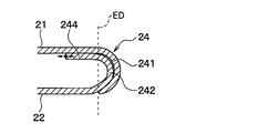
- the second curved portion 24 extends from the end portion on the other end side (right side) of the first flat plate portion 21, and the outer wall portion 241 constituting the outer wall of the tubular member 20 and the other end of the second flat plate portion 22.
- An inner wall portion 242 that extends from the end portion on the side (right side) and forms the inner wall of the tubular member 20 is configured.
- the 2nd curved part 24 comprises the junction part (double wall) joined by brazing in the state in which the inner wall face of the outer wall part 241 and a part of outer wall face of the inner wall part 242 overlap.
- the inner wall portion 242 of the second curved portion 24 is formed with a curved surface in which a portion (outer wall surface) facing the outer wall portion 241 is continuously curved. That is, the inner wall portion 242 of this embodiment is not provided with a recess (transition portion) for accommodating the end portion of the outer wall portion 241.
- the outer wall portion 241 is joined so as to extend along a continuous curved surface (outer wall surface) of the inner wall portion 242. That is, the outer wall part 241 is joined in a state of being in close contact with the continuous curved surface of the inner wall part 242.
- the inner wall portion 242 has an extended portion 243 extended from a portion facing the outer wall portion 241, and the distal end portion 244 of the extended portion 243 is joined in a state of being separated from the wall surface of the first flat plate portion 21.
- the extended portion 243 is a portion facing the first flat plate portion 21 in the inner wall portion 242 and is configured to bend continuously from a portion facing the outer wall portion 241 in the inner wall portion 242.
- the extension part 243 is opposed to the part on the first flat plate part 21 side from the boundary (end position ED of the first flat plate part 21) between the first flat plate part 21 and the outer wall part 241 in the major axis direction of the tubular member 20. It is arranged at the position to do.
- ED indicates an end position of the first flat plate portion, that is, a boundary position between the first flat plate portion 21 and the outer wall portion 241.
- the extension part 243 extends from the ED position toward the distal end 244 and is disposed to face the first flat plate part 21.
- the surface of the extended portion 243 that faces the first flat plate portion 21 is the bonding surface portion that joins the flat surface of the first flat plate portion 21 and the first end portion 244 side. It consists of a separation surface portion separated from the flat plate portion 21.
- FIG. 3 is an explanatory diagram for explaining a manufacturing process of the radiator 1.
- the header tank 5 is further assembled, and the temporary assembly state is maintained by restraining with an appropriate jig.
- the flat tubes 2 and the outer fins 3 are appropriately adhered in the stacking direction by the wires 7 (see FIG. 3A) and the clamps 8 (see FIG. 3B). Temporarily fix it with the load applied.
- the assembly in the temporarily assembled state is heated to a temperature equal to or higher than the melting point of the brazing material coated on each member in a vacuum heating furnace or a heating furnace in an inert atmosphere, and the brazing material is melted to assemble. Braze each joint of the body together.
- the direction in which the first flat plate portion 21 and the second flat plate portion 22 approach due to the load by the jig or the lamination of the outer fins 3 when the core portion 4 is assembled (the minor axis direction of the cylindrical member 20). ) Has a compressive force.
- the flat tube 2 is composed of a single metal plate, if variations in the plate length, plate width, strength, etc. of the plate member occur, the compressive force acts on the flat tube 2. As a result, the position of the distal end portion 244 of the inner wall portion 242 in the second curved portion 24 of the cylindrical member 20 varies.
- the distal end portion 244 of the inner wall portion 242 in the second curved portion 24 is not extended to a position facing the first flat plate portion 21, and the distal end portion 244 of the inner wall portion 242 and the outer wall portion 241 are in contact with each other.
- the first flat plate portion 21 is moved as shown in FIGS. 5 (b) and 5 (c). The direction may be changed in the direction of pushing or the outer wall 241 is pushed outward.
- the tip portion 244 of the inner wall portion 242 varies in a direction in which the first flat plate portion 21 is pushed up when a compressive force is applied to the flat tube 2.
- the tip end portion 244 of the inner wall portion 242 in the second curved portion 24 is not extended to a position facing the first flat plate portion 21, and the tip end portion 244 of the inner wall portion 242 and the outer wall portion 241 are separated from each other. Then, as shown in FIGS. 6A and 6B, when the compressive force acts on the flat tube 2, the tip 244 of the inner wall 242 moves to the gap between the outer wall 241 and the tip 244 of the inner wall 242. There are things to do. 4 to 6 are explanatory views for explaining the difference between the tubular member of the present embodiment and the conventional tubular member.
- the distal end portion 244 of the inner wall portion 242 in the second curved portion 24 is extended to a position facing the first flat plate portion 21, and the distal end portion 244 of the inner wall portion 242 and the first flat plate.
- a structure in which the portion 21 is separated is adopted.
- the surface of the extended portion 243 that faces the first flat plate portion 21 is a bonding surface portion that joins the flat surface of the first flat plate portion 21, and the first flat plate on the distal end portion 244 side. It consists of a separation surface portion separated from the portion 21.
- FIG. 8 is a cross-sectional view showing a flow path cross section of the flat tube 2 of the present embodiment
- FIG. 8A shows the entire flow path cross section of the flat tube 2
- FIG. The partial enlarged view of the B section of 8 (a) is shown.
- description of the same or equivalent parts as in the first embodiment will be omitted or simplified.
- the flat tube 2 of the present embodiment has an extended portion 243 that extends the inner wall portion 242 from the portion facing the outer wall portion 241 to the first curved portion 23.
- the extended portion 243 is waved so that the portions (fin portions 243a) facing the flat plate portions 21 and 22 in the minor axis direction of the flat tube 2 function as inner fins that increase the heat transfer area with the engine coolant. It is formed into a shape.
- the fin part 243a is formed so that each wave-shaped top part may contact
- the extension portion 243 has an inner wall surface (fin end portion 243b) facing the first curved portion 23 that is in close contact with the inner peripheral surface of the first curved portion 23, and the second curved portion on the first curved portion 23 side.
- the front end portion 244 facing the flat plate portion 22 is joined in a state of being separated from the second flat plate portion 22.
- the extended portion 243 on the tip end 244 side is joined to the second flat plate portion 22 while being separated from the second flat plate portion 22 at the tip end 244.
- the second flat plate portion. 22 in a state in which the adhesion between the inner wall portion 242 and the outer wall portion 241 and the adhesion between the extended portion 243 in the inner wall portion 242 and the inner peripheral surface of the first curved portion 23 are maintained only by changing the position of the end portion 22. Can be joined. As a result, it is possible to improve the brazing property at the joint portion in the flat tube 2.
- the inner wall part 242 in the 2nd curved part 24 is formed in the curved surface in which the part (outer wall surface) facing the outer wall part 241 curves continuously, it is not limited to this. .
- the inner wall 242 may be provided with a recess 242a for accommodating the end of the outer wall 241.
- the extended portion 243 in the inner wall portion 242 is configured to bend continuously from the portion facing the outer wall portion 241 in the inner wall portion 242, but is not limited to this.
- the extended portion 243 in the inner wall portion 242 may be configured to bend from a portion facing the outer wall portion 241 in the inner wall portion 242.
- the distal end portion 244 of the extension portion 243 in the inner wall portion 242 is separated on the second curved portion 24 side in the first flat plate portion 21, but is not limited thereto.
- the distal end portion 244 of the extension portion 243 in the inner wall portion 242 may be separated on the first curved portion 23 side in the first flat plate portion 21.
- the extension portion 243 is bent in the minor axis direction between the first flat plate portion 21 and the second flat plate portion 22, and the bent portion 243 c is brought into contact with the first flat plate portion 21 and the second flat plate portion 22.
- the first flat plate portion 21 and the second flat plate portion 22 may be configured to function as support columns that support the first flat plate portion 21 and the second flat plate portion 22.
- the first curved portion 23 and the second curved portion 24 have a curved shape, but the first curved portion 23 and the second curved portion 24 have a circular arc shape.
- the shape is not limited, and may be a combination of circles having different radii of curvature.
- the shape of the 1st music part 23 and the 2nd music part 24 may be the shape which combined the curved surface and the flat surface parallel to the minor axis direction of the cylindrical member 20.
Landscapes
- Engineering & Computer Science (AREA)
- Mechanical Engineering (AREA)
- Physics & Mathematics (AREA)
- Thermal Sciences (AREA)
- General Engineering & Computer Science (AREA)
- Heat-Exchange Devices With Radiators And Conduit Assemblies (AREA)
Abstract
Description
本発明の第1実施形態について図1~図7に基づいて説明する。ここで、図1は、本実施形態に係るラジエータ1の正面図である。
次に、本発明の第2実施形態について図8に基づいて説明する。ここで、図8は、本実施形態の扁平チューブ2の流路断面を示す断面図であり、図8(a)が扁平チューブ2の流路断面の全体を示し、図8(b)が図8(a)のB部の部分拡大図を示している。なお、本実施形態では、第1実施形態と同様または均等な部分についての説明は、省略または簡略化して説明する。
以上、本発明の実施形態について説明したが、本発明はこれに限定されるものではなく、各請求項に記載した範囲を逸脱しない限り、各請求項の記載文言に限定されず、当業者がそれらから容易に置き換えられる範囲にも及び、かつ、当業者が通常有する知識に基づく改良を適宜付加することができる。例えば、以下のように種々変形可能である。
Claims (5)
- 熱交換媒体が流通すると共に、前記熱交換媒体の流通する方向と直交する流路断面が扁平形状に形成された板状部材からなる筒状部材(20)を備える熱交換器用チューブにおいて、
前記筒状部材(20)は、前記流路断面の短径方向において並行に対向する一対の平板部(21、22)と、前記流路断面の長径方向において対向すると共に、前記一対の平板部(21、22)同士を繋ぐ一対の曲部(23、24)と、を有して構成されており、
前記一対の曲部(23、24)のうち一方の曲部(24)は、前記一対の平板部(21、22)における端部から延びて前記筒状部材(20)の外壁を構成する外壁部(241)と、前記一対の平板部(21、22)における端部から延びて前記筒状部材(20)の内壁を構成する内壁部(242)とが重なり合った状態でろう付けによって接合される接合部を構成し、
前記内壁部(242)は、前記外壁部(241)と対向する部位が前記外壁部(241)と密着すると共に、前記平板部(21)と対向する先端部(244)が前記平板部(21)から離間した状態で接合されていることを特徴とする熱交換器用チューブ。 - 前記一対の曲部(23、24)それぞれは、弧状に湾曲していることを特徴とする請求項1に記載の熱交換器用チューブ。
- 前記内壁部(242)は、前記外壁部(241)と対向する部位が連続して湾曲する曲面で形成されており、
前記外壁部(241)は、前記内壁部(242)の連続して湾曲する曲面に沿って延びるように接合されていることを特徴とする請求項1または2に記載の熱交換器用チューブ。 - 前記内壁部(242)は、前記外壁部(241)と対向する部位から他方の曲部(23)側へと延長した延長部位(243)を有し、
前記延長部位(243)は、
前記平板部(21、22)に対向する部位がインナーフィンとして機能するように波形状に形成され、
さらに、前記他方の曲部(23)の内壁面に対向する部位が前記他方の曲部(23)の内周面に沿って密着すると共に、前記他方の曲部(23)側における前記平板部(21、22)と対向する先端部(244)が前記平板部(21、22)から離間した状態で接合されていることを特徴とする請求項1ないし3のいずれか1つに記載の熱交換器用チューブ。 - 前記内壁部(242)は、前記外壁部(241)と対向する部位から先端部(244)まで延び、前記平板部(21、22)の一部と対向する延長部位(243)を有し、
前記延長部位(243)における平板部(21,22)と対向する面は、平板部(21,22)の平面と接合する接合面部と、前記先端部(244)側で前記平板部(21,22)と離間された離間面部よりなることを特徴とする請求項1ないし3のいずれか1つに記載の熱交換器用チューブ。
Priority Applications (4)
| Application Number | Priority Date | Filing Date | Title |
|---|---|---|---|
| US13/883,592 US20130220585A1 (en) | 2010-11-11 | 2011-11-04 | Tube for heat exchanger |
| EP11840495.3A EP2639539A4 (en) | 2010-11-11 | 2011-11-04 | TUBE FOR A HEAT EXCHANGER |
| CN2011800540216A CN103201582A (zh) | 2010-11-11 | 2011-11-04 | 用于热交换器的管 |
| BR112013010570A BR112013010570A2 (pt) | 2010-11-11 | 2011-11-04 | tubo para um trocador de calor |
Applications Claiming Priority (2)
| Application Number | Priority Date | Filing Date | Title |
|---|---|---|---|
| JP2010-252807 | 2010-11-11 | ||
| JP2010252807A JP5527169B2 (ja) | 2010-11-11 | 2010-11-11 | 熱交換器用チューブ |
Publications (1)
| Publication Number | Publication Date |
|---|---|
| WO2012063443A1 true WO2012063443A1 (ja) | 2012-05-18 |
Family
ID=46050612
Family Applications (1)
| Application Number | Title | Priority Date | Filing Date |
|---|---|---|---|
| PCT/JP2011/006169 Ceased WO2012063443A1 (ja) | 2010-11-11 | 2011-11-04 | 熱交換器用チューブ |
Country Status (6)
| Country | Link |
|---|---|
| US (1) | US20130220585A1 (ja) |
| EP (1) | EP2639539A4 (ja) |
| JP (1) | JP5527169B2 (ja) |
| CN (1) | CN103201582A (ja) |
| BR (1) | BR112013010570A2 (ja) |
| WO (1) | WO2012063443A1 (ja) |
Cited By (1)
| Publication number | Priority date | Publication date | Assignee | Title |
|---|---|---|---|---|
| EP3190372A1 (de) | 2016-01-08 | 2017-07-12 | Mahle International GmbH | Flachrohr für einen wärmeübertrager |
Families Citing this family (14)
| Publication number | Priority date | Publication date | Assignee | Title |
|---|---|---|---|---|
| JP5861549B2 (ja) * | 2012-04-04 | 2016-02-16 | 株式会社デンソー | チューブ及び該チューブを備えた熱交換器 |
| JP2014149137A (ja) * | 2013-02-04 | 2014-08-21 | Keihin Thermal Technology Corp | 扁平状熱交換管およびその製造方法 |
| JP5749305B2 (ja) * | 2013-09-03 | 2015-07-15 | 三桜工業株式会社 | 伝熱管、伝熱管の製造方法及び熱交換器 |
| JP6209078B2 (ja) * | 2013-12-20 | 2017-10-04 | 株式会社ティラド | ヘッダプレートレス型熱交換器 |
| US10260821B2 (en) | 2014-07-30 | 2019-04-16 | T.Rad Co., Ltd. | Flat tube for header-plateless heat exchanger |
| JP2016153718A (ja) * | 2015-02-12 | 2016-08-25 | カルソニックカンセイ株式会社 | 熱交換器、熱交換器の組み立て装置、及び熱交換器の組み立て方法 |
| FR3036468A1 (fr) * | 2015-05-22 | 2016-11-25 | Delphi Automotive Systems Lux | Tube plat pour echangeur thermique |
| US11701627B2 (en) | 2017-09-08 | 2023-07-18 | Koch-Glitsch, Lp | Countercurrent contacting devices and method of manufacture |
| US11654405B2 (en) | 2017-09-08 | 2023-05-23 | Koch-Glitsch, Lp | Countercurrent contacting devices and method of manufacture |
| KR101899456B1 (ko) * | 2017-11-27 | 2018-09-18 | 주식회사 코렌스 | 내식성이 향상된 이지알 쿨러용 가스튜브 |
| CN111387563B (zh) * | 2018-12-29 | 2022-11-11 | 云南喜科科技有限公司 | 一种适用于蜂窝状加热不燃烧烟弹的烟具 |
| EP3690372A1 (en) * | 2019-02-01 | 2020-08-05 | Valeo Autosystemy SP. Z.O.O. | Heat exchanger for motor vehicle |
| EP3927453B1 (en) * | 2019-02-21 | 2026-04-29 | Koch-Glitsch, LP | Countercurrent contacting devices |
| LU101492B1 (en) * | 2019-11-25 | 2021-05-26 | Ht Holding Luxembourg S A | Flat heat exchanger tube |
Citations (6)
| Publication number | Priority date | Publication date | Assignee | Title |
|---|---|---|---|---|
| JP2001137989A (ja) * | 1999-09-29 | 2001-05-22 | Valeo Inc | 熱交換器用チューブ |
| JP2001165587A (ja) * | 1999-12-06 | 2001-06-22 | Mitsubishi Heavy Ind Ltd | 熱交換器用チューブ |
| JP2002130969A (ja) * | 2000-10-24 | 2002-05-09 | Japan Climate Systems Corp | 熱交換器用チューブ |
| JP2002174494A (ja) * | 2000-12-06 | 2002-06-21 | Japan Climate Systems Corp | 熱交換器用チューブ |
| JP2009198132A (ja) * | 2008-02-25 | 2009-09-03 | Denso Corp | 熱交換器用チューブ |
| JP2009229024A (ja) * | 2008-03-25 | 2009-10-08 | Denso Corp | 熱交換器用チューブ |
Family Cites Families (4)
| Publication number | Priority date | Publication date | Assignee | Title |
|---|---|---|---|---|
| DE3725602A1 (de) * | 1987-08-01 | 1989-02-09 | Sueddeutsche Kuehler Behr | Flachrohr fuer einen waermetauscher |
| FR2811746B1 (fr) * | 2000-07-12 | 2002-11-01 | Valeo Thermique Moteur Sa | Tube pour echangeur de chaleur, en particulier de vehicule automobile, et echangeur de chaleur comportant de tels tubes |
| JP2005083700A (ja) * | 2003-09-10 | 2005-03-31 | Zexel Valeo Climate Control Corp | 熱交換チューブ |
| BRPI0513873B1 (pt) * | 2004-07-28 | 2021-05-04 | Valeo, Inc | Conjunto trocador de calor e método para fabricar conjunto trocador de calor |
-
2010
- 2010-11-11 JP JP2010252807A patent/JP5527169B2/ja not_active Expired - Fee Related
-
2011
- 2011-11-04 US US13/883,592 patent/US20130220585A1/en not_active Abandoned
- 2011-11-04 CN CN2011800540216A patent/CN103201582A/zh active Pending
- 2011-11-04 BR BR112013010570A patent/BR112013010570A2/pt not_active Application Discontinuation
- 2011-11-04 WO PCT/JP2011/006169 patent/WO2012063443A1/ja not_active Ceased
- 2011-11-04 EP EP11840495.3A patent/EP2639539A4/en not_active Withdrawn
Patent Citations (6)
| Publication number | Priority date | Publication date | Assignee | Title |
|---|---|---|---|---|
| JP2001137989A (ja) * | 1999-09-29 | 2001-05-22 | Valeo Inc | 熱交換器用チューブ |
| JP2001165587A (ja) * | 1999-12-06 | 2001-06-22 | Mitsubishi Heavy Ind Ltd | 熱交換器用チューブ |
| JP2002130969A (ja) * | 2000-10-24 | 2002-05-09 | Japan Climate Systems Corp | 熱交換器用チューブ |
| JP2002174494A (ja) * | 2000-12-06 | 2002-06-21 | Japan Climate Systems Corp | 熱交換器用チューブ |
| JP2009198132A (ja) * | 2008-02-25 | 2009-09-03 | Denso Corp | 熱交換器用チューブ |
| JP2009229024A (ja) * | 2008-03-25 | 2009-10-08 | Denso Corp | 熱交換器用チューブ |
Non-Patent Citations (1)
| Title |
|---|
| See also references of EP2639539A4 * |
Cited By (2)
| Publication number | Priority date | Publication date | Assignee | Title |
|---|---|---|---|---|
| EP3190372A1 (de) | 2016-01-08 | 2017-07-12 | Mahle International GmbH | Flachrohr für einen wärmeübertrager |
| DE102016200152A1 (de) | 2016-01-08 | 2017-07-13 | Mahle International Gmbh | Flachrohr für einen Wärmeübertrager |
Also Published As
| Publication number | Publication date |
|---|---|
| US20130220585A1 (en) | 2013-08-29 |
| EP2639539A1 (en) | 2013-09-18 |
| BR112013010570A2 (pt) | 2016-08-09 |
| JP5527169B2 (ja) | 2014-06-18 |
| JP2012102948A (ja) | 2012-05-31 |
| EP2639539A4 (en) | 2014-11-26 |
| CN103201582A (zh) | 2013-07-10 |
Similar Documents
| Publication | Publication Date | Title |
|---|---|---|
| JP5527169B2 (ja) | 熱交換器用チューブ | |
| CN108139183B (zh) | 热交换器 | |
| JP4171760B2 (ja) | 偏平管および偏平管の製造方法 | |
| WO1998044306A1 (fr) | Tube pour echangeur de chaleur et procede de fabrication de ce dernier | |
| US9726439B2 (en) | Tube and heat exchanger provided with tube | |
| JP2007303813A (ja) | 自己ブレーキラジエータ側板 | |
| JP3901349B2 (ja) | 熱交換器用扁平伝熱管 | |
| WO2017013918A1 (ja) | 熱交換器 | |
| JP2014035181A (ja) | 熱交換器のためのチューブ、熱交換器のチューブアッセンブリ及びその製造方法 | |
| CN103492827A (zh) | 制造用于热交换器的双鼻部管件的方法 | |
| EP1455154A2 (en) | Evaporator | |
| US20080264620A1 (en) | Flat Tube, Platelike Body for Making the Flat Tube and Heat Exchanger | |
| JP5568330B2 (ja) | 熱交換器 | |
| JP2006078163A (ja) | 偏平管、偏平管製造用板状体および熱交換器 | |
| JP2011163700A5 (ja) | ||
| JP2001174190A (ja) | 複式熱交換器 | |
| JP4059186B2 (ja) | ろう付け扁平チューブ | |
| JP4626472B2 (ja) | 熱交換器および熱交換器の製造方法 | |
| JP6632868B2 (ja) | アルミニウム製熱交換器 | |
| JP5359288B2 (ja) | 熱交換器 | |
| JP4103762B2 (ja) | ろう付け扁平チューブ | |
| JP2009168356A (ja) | 熱交換器用チューブ | |
| JP4764647B2 (ja) | 偏平管製造用板状体、偏平管、熱交換器および熱交換器の製造方法 | |
| JP6106546B2 (ja) | 熱交換装置 | |
| JP2019184166A (ja) | 熱交換器 |
Legal Events
| Date | Code | Title | Description |
|---|---|---|---|
| 121 | Ep: the epo has been informed by wipo that ep was designated in this application |
Ref document number: 11840495 Country of ref document: EP Kind code of ref document: A1 |
|
| WWE | Wipo information: entry into national phase |
Ref document number: 2011840495 Country of ref document: EP |
|
| WWE | Wipo information: entry into national phase |
Ref document number: 13883592 Country of ref document: US |
|
| NENP | Non-entry into the national phase |
Ref country code: DE |
|
| REG | Reference to national code |
Ref country code: BR Ref legal event code: B01A Ref document number: 112013010570 Country of ref document: BR |
|
| ENP | Entry into the national phase |
Ref document number: 112013010570 Country of ref document: BR Kind code of ref document: A2 Effective date: 20130429 |