WO2012063528A1 - コネクタ及びスイッチ - Google Patents
コネクタ及びスイッチ Download PDFInfo
- Publication number
- WO2012063528A1 WO2012063528A1 PCT/JP2011/066308 JP2011066308W WO2012063528A1 WO 2012063528 A1 WO2012063528 A1 WO 2012063528A1 JP 2011066308 W JP2011066308 W JP 2011066308W WO 2012063528 A1 WO2012063528 A1 WO 2012063528A1
- Authority
- WO
- WIPO (PCT)
- Prior art keywords
- contact
- movable
- fixed
- card
- slide
- Prior art date
- Legal status (The legal status is an assumption and is not a legal conclusion. Google has not performed a legal analysis and makes no representation as to the accuracy of the status listed.)
- Ceased
Links
Images














Classifications
-
- H—ELECTRICITY
- H01—ELECTRIC ELEMENTS
- H01H—ELECTRIC SWITCHES; RELAYS; SELECTORS; EMERGENCY PROTECTIVE DEVICES
- H01H13/00—Switches having rectilinearly-movable operating part or parts adapted for pushing or pulling in one direction only, e.g. push-button switch
- H01H13/02—Details
- H01H13/12—Movable parts; Contacts mounted thereon
- H01H13/14—Operating parts, e.g. push-button
-
- H—ELECTRICITY
- H01—ELECTRIC ELEMENTS
- H01H—ELECTRIC SWITCHES; RELAYS; SELECTORS; EMERGENCY PROTECTIVE DEVICES
- H01H1/00—Contacts
- H01H1/58—Electric connections to or between contacts; Terminals
- H01H1/5866—Electric connections to or between contacts; Terminals characterised by the use of a plug and socket connector
-
- H—ELECTRICITY
- H01—ELECTRIC ELEMENTS
- H01H—ELECTRIC SWITCHES; RELAYS; SELECTORS; EMERGENCY PROTECTIVE DEVICES
- H01H15/00—Switches having rectilinearly-movable operating part or parts adapted for actuation in opposite directions, e.g. slide switch
- H01H15/02—Details
- H01H15/06—Movable parts; Contacts mounted thereon
- H01H15/16—Driving mechanisms
-
- H—ELECTRICITY
- H01—ELECTRIC ELEMENTS
- H01R—ELECTRICALLY-CONDUCTIVE CONNECTIONS; STRUCTURAL ASSOCIATIONS OF A PLURALITY OF MUTUALLY-INSULATED ELECTRICAL CONNECTING ELEMENTS; COUPLING DEVICES; CURRENT COLLECTORS
- H01R13/00—Details of coupling devices of the kinds covered by groups H01R12/70 or H01R24/00 - H01R33/00
- H01R13/66—Structural association with built-in electrical component
- H01R13/70—Structural association with built-in electrical component with built-in switch
-
- H—ELECTRICITY
- H01—ELECTRIC ELEMENTS
- H01H—ELECTRIC SWITCHES; RELAYS; SELECTORS; EMERGENCY PROTECTIVE DEVICES
- H01H2205/00—Movable contacts
- H01H2205/002—Movable contacts fixed to operating part
-
- H—ELECTRICITY
- H01—ELECTRIC ELEMENTS
- H01H—ELECTRIC SWITCHES; RELAYS; SELECTORS; EMERGENCY PROTECTIVE DEVICES
- H01H9/00—Details of switching devices, not covered by groups H01H1/00 - H01H7/00
- H01H9/02—Bases, casings, or covers
- H01H9/0264—Protective covers for terminals
-
- H—ELECTRICITY
- H01—ELECTRIC ELEMENTS
- H01R—ELECTRICALLY-CONDUCTIVE CONNECTIONS; STRUCTURAL ASSOCIATIONS OF A PLURALITY OF MUTUALLY-INSULATED ELECTRICAL CONNECTING ELEMENTS; COUPLING DEVICES; CURRENT COLLECTORS
- H01R2103/00—Two poles
-
- H—ELECTRICITY
- H01—ELECTRIC ELEMENTS
- H01R—ELECTRICALLY-CONDUCTIVE CONNECTIONS; STRUCTURAL ASSOCIATIONS OF A PLURALITY OF MUTUALLY-INSULATED ELECTRICAL CONNECTING ELEMENTS; COUPLING DEVICES; CURRENT COLLECTORS
- H01R24/00—Two-part coupling devices, or either of their cooperating parts, characterised by their overall structure
- H01R24/76—Two-part coupling devices, or either of their cooperating parts, characterised by their overall structure with sockets, clips or analogous contacts and secured to apparatus or structure, e.g. to a wall
- H01R24/78—Two-part coupling devices, or either of their cooperating parts, characterised by their overall structure with sockets, clips or analogous contacts and secured to apparatus or structure, e.g. to a wall with additional earth or shield contacts
Definitions
- the present invention relates to a connector and a switch.
- an electrical device operates by receiving power from a power source or the like, and usually power is supplied from the power source to the electrical device via a connector.
- a connector for example, a convex male type connector and a concave female type connector are fitted to each other to electrically connect them.
- the human body may be affected or the operation of the electronic component may be affected.
- the connector which is an electrically connected part, is installed on the human body rather than a normal AC commercial power source when installing or maintaining the apparatus. In some cases, it is necessary to consider the influence on the operation of electronic components.
- an object of the present invention is to provide a connector that can safely supply high-voltage power.
- An object of the present invention is to provide a switch that is compatible with a power supply having a voltage higher than the voltage or a DC power supply and that has high safety and reliability.
- connection terminal connected to another connection terminal in another connector, a fixed contact, a movable contact provided at one end of the movable plate, and an insulator
- a card that contacts the movable plate part, a button that contacts the card, a release spring connected to the button, and a contact between the fixed contact and the movable contact.
- Slide operation unit and either one of the fixed contact or the movable contact is connected to the connection terminal, and by moving the slide operation unit in one direction, When the button is pressed, the movable plate moves through the card, and the fixed contact and the movable contact come into contact with each other, and the release spring is turned on from the on state.
- a restoring force acts in a direction in which the contact with the movable contact is released, and the restoring force of the breaking spring is obtained by moving the slide operation unit in the other direction opposite to the one direction. Due to this, the fixed contact and the movable contact are separated from each other and are turned off.
- the upper surface of the button has a lower step portion formed with a low height, an upper step portion formed with a high height, the bottom portion, and the upper step portion. And a contact slide portion that operates in response to the operation of the slide operation portion.In the off state, the tip of the contact slide portion is placed on the bottom surface portion of the button. The button is pressed when the tip of the contact slide part comes into contact with the upper stage part of the button in the ON state.
- the contact slide portion has a contact slide contact portion that contacts the contact slide opening and the button, and corresponds to the operation of the slide operation portion.
- a part of the slide link part that operates in this manner is in the contact slide opening, and by sliding the slide operation part, the slide link part moves in a direction substantially parallel to the slide direction, and the slide link One contact portion or the other end portion of the contact slide opening is pushed by a part of the portion, so that the contact slide portion moves substantially parallel to the slide direction.
- the other connector is provided with a connector connection opening, and in the on state, a hook is inserted into the connector connection opening. To do.
- the card has a first contact portion that contacts one surface of the movable plate portion and a second contact portion that contacts the other surface. It is characterized by being.
- the fixed contact and the movable contact are installed in a region surrounded by the switch case and the base block, and the release spring includes the switch It is provided outside the case.
- the case is provided with an opening
- the card is a card body portion that is present in an area surrounded by the case and the base block.
- a projecting portion having a shape protruding from the opening in the case to the outside of the case, and in an off state, the opening in the case and the upper surface of the card main body are in contact with each other It is characterized by being.
- a wall is provided in the vicinity of the opening in the case, and the button covers the wall of the case in the on state. It has the formed edge part, It is characterized by the above-mentioned.
- the card is connected to the base block in a rotatable state.
- the fixed contact is provided at one end of a fixed spring, and the other end of the fixed spring is connected to the base block,
- the other end portion of the movable plate portion is connected to one end portion of the movable spring, and the other end portion of the movable spring is connected to the base block, and is located between the fixed spring and the movable spring. Is provided with an insulating wall.
- a permanent magnet is provided in the vicinity of a contact position between the fixed contact and the movable contact.
- a plurality of the fixed contacts and the movable contacts are provided.
- the plurality of the fixed contacts and the movable contacts that are in contact with the movable contacts corresponding to the fixed contacts at the same time by the button is characterized by.
- curd which is formed with the fixed contact, the movable contact provided in one edge part of the movable board part, and the insulator, and contacts the said movable board part
- the card has a first contact portion that contacts one surface of the movable plate portion and a second contact portion that contacts the other surface. It is characterized by being.
- the fixed contact and the movable contact are installed in a region surrounded by the case and the base block, and the release spring is provided outside the case. It is characterized by being provided.
- the case is provided with an opening
- the card is a card body portion that is present in an area surrounded by the case and the base block.
- a projecting portion having a shape protruding from the opening in the case to the outside of the case, and in the off state, the opening in the case and the upper surface of the card body portion are in contact with each other It is characterized by being.
- a wall is provided in the vicinity of the opening in the case, and the button covers the wall of the case in the on state. It has the formed edge part, It is characterized by the above-mentioned.
- the card is connected to the base block in a rotatable state.
- the fixed contact is provided at one end of a fixed spring, and the other end of the fixed spring is connected to the base block,
- the other end portion of the movable plate portion is connected to one end portion of the movable spring, and the other end portion of the movable spring is connected to the base block, and is located between the fixed spring and the movable spring. Is provided with an insulating wall.
- an electric wire is used instead of the movable spring.
- a permanent magnet is provided in the vicinity of a contact position between the fixed contact and the movable contact.
- a plurality of the fixed contacts and the movable contacts are provided.
- the plurality of the fixed contacts and the movable contacts that are in contact with the movable contacts corresponding to the fixed contacts at the same time by the button is characterized by.
- a power supply having a voltage higher than the voltage of the current commercial power supply or a connector corresponding to a direct current power supply which can safely supply power from these power supplies.
- a switch that is compatible with a power supply having a voltage higher than that of the current commercial power supply or a DC power supply and having high safety and reliability. Can do.
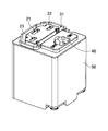
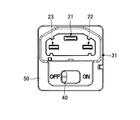
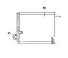
- the perspective view of the connector in a 1st embodiment The front view of the connector in a 1st embodiment Side view of the connector in the first embodiment
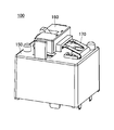
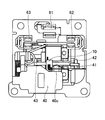
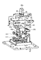
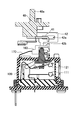
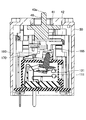
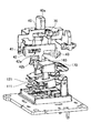
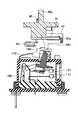
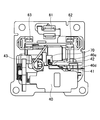
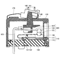
- the internal structure figure of the connector in a 1st embodiment Perspective view of switch Structure of switch part (OFF state) Structure of switch part (ON state) Explanatory drawing before the connection of the connector and plug connector in 1st Embodiment Explanatory drawing of the OFF state after the connection of the connector and plug connector in 1st Embodiment Explanatory drawing of the ON state after the connection of the connector and plug connector in 1st Embodiment
- the internal structure figure seen from the side of the OFF state of the connector in a 1st embodiment The internal structure figure seen from the upper surface of the OFF state of the connector in a 1st embodiment
- the principal part side view of the step which transfers to the ON state from the OFF state of the connector in 1st Embodiment The internal structure figure seen from the side of the ON state of the connector in a 1st embodiment
- the internal structure figure seen from the upper surface of the ON state of the connector in a 1st embodiment The principal part perspective view of the ON state of the connector in 1st Embodiment
- the connector in the first embodiment is connected to a plug connector which is another connector shown in FIGS. 1 to 5, and corresponds to a jack connector having a structure shown in FIGS. .
- the plug connector shown in FIGS. 1 to 5 and the connector corresponding to the jack connector shown in FIGS. 6 to 8 may be collectively referred to as a connector.
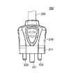
- FIGS. 1 is a perspective view of the plug connector 200
- FIG. 2 is a top view
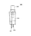
- FIG. 3 is a side view
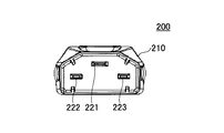
- FIG. 4 is a bottom view
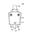
- FIG. 5 is a front view.
- the plug connector 200 has a cover 210 formed of an insulator or the like and three plug terminals 221, 222, 223 which are other connection terminals.
- the three plug terminals 221, 222, 223 are A power cable 230 is connected to the side opposite to the provided side.
- the plug terminal 221 is a GND terminal and is longer than the plug terminals 222 and 223.
- the plug terminals 222 and 223 are terminals to which electric power is supplied by being electrically connected.
- the plug connector 200 includes a protection portion 211 formed in a shape that covers a part of the plug terminals 221, 222, and 223 in the cover 210 portion on the side where the plug terminals 221, 222, and 223 are provided. Furthermore, a connector connection opening 212 is provided so that the connector connection does not come off after being connected to the connector in the first embodiment.
- FIGS. 6 is a perspective view of the connector according to the present embodiment
- FIG. 7 is a front view
- FIG. 8 is a side view.
- the connector according to the present embodiment is entirely covered with the housing 50, and the jack openings 21, 22, and 23 into which the plug terminals 221, 222, and 223 of the plug connector 200 are inserted, and the protective portion of the plug connector 200.
- a slide operation unit 40 is provided for controlling whether or not power is supplied in a state in which the groove portion 31 into which 211 is inserted and the plug connector 200 and the connector in the present embodiment are connected. .
- the slide operation unit 40 can be slid so as to be in the “ON” position or the “OFF” position. Whether or not power is supplied via the connector by sliding the slide operation unit 40. Can be controlled.
- FIG. 9 is a cross-sectional view showing the internal structure of the connector in the present embodiment.
- the slide operation upper portion 40a of the slide operation unit 40 has a shape protruding outward from the opening provided in the housing 50, and the slide operation upper portion 40a is moved from the outside of the housing 50 to the arrow A. By moving in the sliding direction indicated by, it is possible to perform an operation as to whether or not to perform electrical connection in the switch unit 100 inside the housing 50.
- the slide operation unit 40 has a slide operation main body 40 b in the housing 50, and the slide operation main body 40 b is connected to the slide link unit 41.
- the slide link portion 41 operates substantially in parallel with the slide direction indicated by the arrow A, and is formed in an L shape.
- One end of the L shape is a contact slide opening of the contact slide portion 42.
- the structure is embedded in the portion 42a.
- the contact slide opening 42a is formed in an elongated shape along the moving direction of the slide link portion 41, that is, the sliding direction indicated by the arrow A.
- the contact slide portion 42 is provided with a contact slide contact portion that extends in a direction substantially perpendicular to the slide direction indicated by the arrow A.
- the top surface of the button 160 is touched.
- the switch unit 100 of the connector in the present embodiment is a switch for controlling power supply, and is also referred to as a power switch.
- FIG. 10 is a perspective view of the switch unit 100
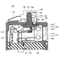
- FIG. 11 is an internal structure diagram of the switch unit 100. As shown in FIG. 11, the switch unit 100 can perform on / off control of power supply depending on whether the fixed contact 111 in the fixed unit 110 and the movable contact 121 in the movable unit 120 are in contact with each other. It can be done.
- the fixed part 110 is entirely formed of a conductive material such as metal, and has a structure in which a fixed contact 111 that contacts the movable contact 121 in the movable part 120 is provided at one end of the fixed spring 112. It is.
- the fixed spring 112 is formed by bending a metal plate or the like made of copper or an alloy containing copper, and the fixed contact 111 is formed of an alloy of silver and copper.
- the other end of the fixed spring 112 is fixed at the base block main body 131 in the base block 130, and is supported and fixed at the fixed portion support portion 132 in the middle of the fixed spring 112.
- the movable portion 120 is entirely formed of a conductive material such as metal, and a movable contact 121 that contacts the fixed contact 111 in the fixed portion 110 is provided at one end of the movable plate portion 122.
- the other end of 122 and one end of the movable spring 123 are connected.
- the movable plate portion 122 and the movable spring 123 are formed by bending a metal plate made of copper or an alloy containing copper, and the movable contact 121 is made of an alloy of silver and copper.
- the other end of the movable spring 123 is fixed to the base block main body 131 in the base block 130, but the movable spring 123 is formed by bending a metal plate or the like so that it has flexibility.
- the movable contact 121 provided at one end of the movable plate portion 122 can be moved in the vertical direction.
- an insulating wall 133 made of a flame-retardant resin material or the like is provided between the portion where the other of the fixed spring 112 is connected to the base block 130 and the portion where the other of the movable spring 123 is connected.
- the movable spring 123 is bent in such a shape as to wrap around a part of the periphery of the insulating wall 133 from the other end.
- the upper surface that is one surface of the movable plate portion 122 in the movable portion 120 is in contact with the upper contact portion 141 that is the first contact portion in the card 140, and the lower surface that is the other surface of the movable plate portion 122 is The card 140 is in contact with the lower contact portion 142 serving as the second contact portion.
- the movable plate portion 122 comes into contact with the upper contact portion 141 or the lower contact portion 142, and a force is applied to move the movable contact 121 in the vertical direction. Can do.
- the surface of the upper contact portion 141 and the lower contact portion 142 has a fluororesin or the like to reduce frictional resistance. You may provide the surface layer formed by these.
- the fixed portion 110 and the movable portion 120 are installed inside a region surrounded by the base block 130 and the switch portion case 150, and the card 140 is inserted from the switch portion opening 151 provided in the switch portion case 150.
- a protrusion 144 having a shape protruding outward, and a card main body 145 located inside a region surrounded by the base block 130 and the switch case 150 are provided. Therefore, in the switch unit 100, the upper contact part 141 or the lower contact part 142 is provided in an area surrounded by the base block 130 and the switch part case 150.
- the card 140, the base block 130, and the switch case 150 are made of an insulating material made of a resin material or the like.
- a button 160 that is pressed to rotate the card 140 about the rotation shaft 143 is provided outside the switch unit case 150.
- the card 140 is provided on an upper portion of the protrusion 144 of the card 140.
- the contact portion 144a is in contact with the inner wall portion 161 of the button 160. Since the contact portion 144a slides on the surface of the inner wall portion 161, a surface layer formed of a fluororesin or the like may be provided on the surface of the inner wall portion 161 in order to reduce frictional resistance.
- a release spring 170 having one end connected to the switch unit case 150 and the other end connected to the button 160 is provided outside the switch unit case 150.
- the button 160 is turned off by the restoring force of the release spring 170 by moving the contact slide contact part in the contact slide part 42, as will be described later.
- the card 140 in contact with the contact portion 141 in the inner wall portion 161 of the button 160 rotates around the rotation shaft 143, and the movable plate portion in the movable portion 120 via the lower contact portion 142.
- a force is applied to 122 upward.
- the contact between the movable contact 121 and the fixed contact 111 can be released by the upward force applied to the movable plate portion 122, and the supply of power from the power source can be stopped.
- a permanent magnet 180 that generates a magnetic field substantially perpendicular to the direction in which the arc is generated is provided.
- the breaking spring 170 provided outside the switch unit case 150 is used. It is turned off by the restoring force. For this reason, even when the movable spring 123 or the like in the movable portion 120 does not have a restoring force, the power can be turned off. Further, even when a part of the movable spring 123 or the like is melted by heat and the function as a spring is lost, the power of the breaking spring 170 is not affected by the spring property without using the restoring force of the movable spring 123 or the like.
- release spring 170 is installed outside the switch unit case 150, the release spring 170 is not affected by heat or the like that the fixed unit 110 and the movable unit 120 may receive in the switch unit case 150.
- an insulating wall 133 is provided between the portion of the base block 130 where the other fixed spring 112 is connected and the portion of the movable spring 123 connected. .
- the switch unit 100 when dust or the like enters the area surrounded by the base block 130 and the case 150, a short circuit or poor contact may occur between the fixed contact 111 and the movable contact 121. Therefore, when the switch unit 100 is in the OFF state, the card body 145 of the card 140 is closed so as to close the opening 151 in the case 150 in order to prevent dust and the like from entering the area surrounded by the base block 130 and the case 150. It is formed so that the upper surface of the can be pressed in contact. Accordingly, it is possible to prevent dust and the like from entering the inside of the case 150 from the opening 151 when the switch unit 100 is in the OFF state.
- a U-shaped end portion 162 provided at 160 is provided.
- the wall portion 152 of the case 150 is formed so as to cover the U-shaped end portion 162 provided on the button 160 and can be blocked by the wall portion 152 and the end portion 162. . Thereby, it is possible to prevent dust and the like from entering the inside of the case 150 from the opening 151 when the switch unit 100 is on.
- the switch unit 100 can be turned on and off by controlling on and off in the connector in this embodiment, and the power supply It is possible to control the supply of power from such as.
- the connector and the plug connector 200 in the present embodiment are connected as shown in FIG. To do.
- the slide operation upper part 40a of the slide operation unit 40 of the connector in this embodiment remains in the “OFF” position and is in the off state, it is not electrically connected and is not connected via the connector. No power or the like is supplied.
- the slide operation upper part 40 a of the slide operation unit 40 of the connector in the present embodiment is slid to the “ON” position to be in the ON state.
- the connector in this embodiment and the plug connector 200 are electrically connected to each other, and electric power or the like is supplied through the connector.
- the situation from the off state shown in FIG. 14 to the on state shown in FIG. 15 will be described in more detail.
- FIG. 16 is an internal structure diagram viewed from the side surface side of the connector in the present embodiment in the off state
- FIG. 17 is an internal structure diagram viewed from the front side
- FIG. FIG. 19 is a perspective view of the main part of the mechanism part
- FIG. 20 is a side view of the main part of the internal structure.
- the contact slide portion 42 is provided with a contact slide contact portion 42 b that extends in a direction substantially perpendicular to the slide direction indicated by the arrow A, and is provided on the upper surface of the switch portion 160. In the lower step portion 163 of the groove, the tip of the contact slide contact portion 42b is in contact.
- jack terminals 61, 62, and 63 that are electrically connected to the plug terminals 221, 222, and 223 are provided inside the jack openings 21, 22, and 23 of the connector in the present embodiment.
- the switch unit 100 is provided with two pairs of the fixed unit 110 and the movable unit 120 corresponding to the jack terminals 62 and 63. That is, the jack terminal 62 is connected to one of the pair of fixed portions 110 or the movable portion 120, and the other is connected to a power supply source (not shown).
- the jack terminal 63 is connected to one of the other pair of fixed part 110 and movable part 120, and the other is connected to a power supply source (not shown).
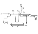
- the hook 70 shown in FIG. 22 is in contact with the narrow portion 40c on the side surface of the slide operation unit 40. In this state, the hook 70 is not in the connector connection opening 212 of the plug connector 200. In this embodiment, the connector and the plug connector 200 can be attached and detached.
- FIG. 23 is an internal structure diagram viewed from the side of the connector in this embodiment in this state
- FIG. 24 is a perspective view of the main part of the mechanism part
- FIG. 25 is the main part of the internal structure. It is a side view.
- the slide operation upper part 40a is at an approximately middle position between the “ON” position and the “OFF” position, and is formed in an L shape on the right side of the contact slide opening 42a in the contact slide part 42.
- One end of the slide link portion 41 comes into contact, and the contact slide portion 42 is slightly moved in the slide direction.
- FIG. 26 is an internal structure diagram viewed from the side surface side of the connector in the present embodiment in this state
- FIG. 27 is an internal structure diagram viewed from the front side
- FIG. FIG. 29 is a perspective view of the main part of the mechanism part
- FIG. 30 is a side view of the main part of the internal structure.
- the slide operation upper part 40a is in the “ON” position, and one of the slide link parts 41 formed in an L shape on the right side of the contact slide opening part 42a in the contact slide part 42 is further pushed.
- the contact slide portion 42 can be further moved.
- the tip of the contact slide contact portion 42 b in the contact slide portion 42 comes into contact with the upper step portion 165 provided in the switch portion 160.
- the button 160 in the switch unit 100 is pushed by the contact slide contact part 42b, the fixed contact 111 in the two pairs of fixed parts 110 and the movable contact 121 in the movable part 120 are in contact with each other.
- This ON state is maintained when the tip of the contact slide contact portion 42 b in the contact slide portion 42 is in contact with the upper step portion 165 provided in the switch portion 160.
- the contact position of the hook 70 shown in FIG. 22 with the side surface of the slide operation unit 40 is changed from the narrow portion 40c on the side surface of the slide operation unit 40 to the inclined portion 40d.
- the slide operation upper part 40a indicated by the arrow A1 is slid in the sliding direction to move in the direction indicated by the arrow B1 which is substantially perpendicular to the sliding direction. Since the moved hook 70 enters and fits into the connector connection opening 212 provided in the plug connector 200, the connection between the connector and the plug connector in the present embodiment is maintained.
- the transition from the on state to the off state is performed by sliding the position of the slide operation upper portion 40a of the connector in this embodiment from the “ON” position to the “OFF” position.
- the position of the slide operation upper part 40 a By sliding the position of the slide operation upper part 40 a in this way, the position where the tip of the contact slide contact part 42 b in the contact slide part 42 is in contact with the inclined part 164 from the upper stage part 165 provided in the switch part 160. Then, it moves to the lower stage part 163.
- the switch unit 160 is lifted by the release spring 170, and the contact between the fixed contact 111 in the two pairs of fixed units 110 and the movable contact 121 in the movable unit 120 is released and is turned off.
- the switch in the second embodiment corresponds to the switch portion in the connector in the first embodiment, and will be described in more detail in the present embodiment.
- the voltage supplied from the power supply is 100 V or more, for example, DC 400 V
- the voltage is high voltage, or because it is DC, for some reason.
- the contacts that are in contact with each other melt and stick together due to heat or the like, and the supply of power may not be cut off. This is a problem as a switch because it completely loses its function as a switch and has a great influence.
- the switch in the present embodiment is a switch for controlling the supply of electric power, and is also referred to as a power switch. As shown in FIG. 31, the switch according to the present embodiment controls on / off of power supply depending on whether the fixed contact 111 in the fixed unit 110 and the movable contact 121 in the movable unit 120 are in contact with each other. Is something that can be done.
- the fixed part 110 is entirely formed of a conductive material such as metal, and has a structure in which a fixed contact 111 that contacts the movable contact 121 in the movable part 120 is provided at one end of the fixed spring 112. It is.
- the fixed spring 112 is formed by bending a metal plate or the like made of copper or an alloy containing copper, and the fixed contact 111 is formed of an alloy of silver and copper.
- the other end of the fixed spring 112 is fixed at the base block main body 131 in the base block 130, and is supported and fixed at the fixed portion support portion 132 in the middle of the fixed spring 112.
- the movable portion 120 is entirely formed of a conductive material such as metal, and a movable contact 121 that contacts the fixed contact 111 in the fixed portion 110 is provided at one end of the movable plate portion 122.
- a movable contact 121 that contacts the fixed contact 111 in the fixed portion 110 is provided at one end of the movable plate portion 122.
- the movable plate portion 122 and the movable spring 123 are made of a metal plate made of copper or an alloy containing copper, and the movable contact 121 is made of an alloy of silver and copper.
- the other end of the movable spring 123 is fixed to the base block main body 131 in the base block 130, but the movable spring 123 is formed by bending a metal plate or the like, so that it has flexibility.
- the movable contact 121 provided at one end of the movable plate portion 122 can be moved in the vertical direction.
- an insulating wall 133 made of a flame-retardant resin material or the like is provided between the portion where the other of the fixed spring 112 is connected to the base block 130 and the portion where the other of the movable spring 123 is connected.
- the movable spring 123 is bent in such a shape as to wrap around a part of the periphery of the insulating wall 133 from the other end.
- the upper surface that is one surface of the movable plate portion 122 in the movable portion 120 is in contact with the upper contact portion 141 that is the first contact portion in the card 140, and the lower surface that is the other surface of the movable plate portion 122 is The card 140 is in contact with the lower contact portion 142 serving as the second contact portion.
- a force is applied via the upper contact portion 141 or the lower contact portion 142 that is in contact with the movable plate portion 122, and the movable contact 121 is moved in the vertical direction. Can be moved.
- the surface of the upper contact portion 141 and the lower contact portion 142 has a fluororesin or the like to reduce frictional resistance. You may provide the surface layer formed by these.
- the fixed portion 110 and the movable portion 120 are installed inside a region surrounded by the base block 130 and the case 150, and the card 140 has a shape that protrudes to the outside from the opening 151 provided in the case 150. It has a projection 144 and a card body 145 located inside a region surrounded by the base block 130 and the case 150. Therefore, in the switch according to the present embodiment, the upper contact portion 141 or the lower contact portion 142 is provided inside a region surrounded by the base block 130 and the case 150. Further, the card 140, the base block 130, and the case 150 are formed of an insulating material made of a resin material or the like.
- a button 160 that is pressed to rotate the card 140 around the rotation shaft 143 is provided outside the case 150, and the card 140 has a contact portion that is provided above the protrusion 144 of the card 140.
- the inner wall portion 161 of the button 160 is in contact. Since the contact portion 144a slides on the surface of the inner wall portion 161, a surface layer formed of a fluororesin or the like may be provided on the surface of the inner wall portion 161 in order to reduce frictional resistance.
- a release spring 170 having one end connected to the case 150 and the other end connected to the button 160 is provided outside the case 150.
- the switch when the switch is turned off, the locking portion of the on-state maintaining mechanism or the like (not shown) is released, and the restoring force due to the spring property of the release spring 170 The switch can be turned off.
- the card 140 in contact with the inner wall 161 of the button 160 at the contact portion 144 a rotates around the rotation shaft 143, and the movable plate portion 122 in the movable portion 120 is rotated by the lower contact portion 142.
- a force is applied upward.
- the contact between the movable contact 121 and the fixed contact 111 can be released by the upward force applied to the movable plate portion 122, and the supply of power from the power source can be stopped.
- the arc is generated near the contact position between the movable contact 121 and the fixed contact 111 so that the arc can be blown by the force of the magnetic field.
- the spring restoring force of the movable spring 123 or the like in the movable portion 120 is not used, but the spring of the breaking spring 170 provided outside the case 150 is restored. It is turned off by force. For this reason, even when the movable spring 123 or the like in the movable portion 120 does not have a restoring force, the power can be turned off. For example, even when part of the movable spring 123 or the like is melted by heat and the function as the spring is lost, the power of the breaking spring 170 is not affected by the spring force of the breaking spring 170 without using the restoring force of the movable spring 123 or the like. Can be turned off, and the supply of power from the power source can be reliably shut off. Further, since the release spring 170 is installed outside the case 150, it is not affected by heat or the like received by the fixed portion 110 and the movable portion 120 inside the case 150.
- an insulating wall 133 is provided between the portion of the base block 130 where the other fixed spring 112 is connected and the portion of the movable spring 123 connected. It has been. As a result, even when the fixing part 110 and the movable part 120 are melted by heat, the insulating wall 133 separates the dissolved part of the fixed part 110 and the dissolved part of the movable part 120, thereby fixing the fixed part. It can be prevented that the current continues to flow while 110 and the movable part 120 are in a state of being melted and bonded.
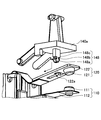
- the card 140 is provided with a circular rotating portion 146 around the rotating shaft 143.
- the base block 130 is provided with a card support part 134 for connecting the card 140, and the circular support part 135 is inserted into the card support part 134 so that the rotating part 146 of the card 140 is inserted. Is provided.
- the rotation unit 146 By inserting the rotation unit 146 into the opening 135, the card 140 is connected to the card support unit 134 in a state of being rotatable around the rotation shaft 143.
- the card 140 is inserted along the movable plate portion 122 with the upper contact portion 141 in contact with the upper side of the movable plate portion 122 and the lower contact portion 142 in contact with the lower side, and the rotating portion 146 has an opening portion 135. It is put in and assembled until it is inserted. Thereby, the movable part 120, the base block 130, and the card
- FIG. 1 The rotation part 146 of the card
- curd 140 is each provided in the edge part of the two rod-shaped parts 147, and is provided so that each rotation part 146 may become an outer side.
- the rotating portion 146 is inserted into the opening 135 of the base block portion 130 by bending the two rod-shaped portions 147 inward.
- the mirror contact process etc. are given to the part which the opening part 135 and the rotation part 146 contact so that frictional resistance may decrease.
- the card support portion 134 is provided with a guide 136 along the insertion direction.
- An inclined portion 137 is provided at an end portion of the portion 134 where the rotating portion 146 enters.
- the movable plate portion 122 has been described as having a structure sandwiched between the upper contact portion 141 and the lower contact portion 142 of the card 140.
- the card 140a may be provided with a protruding connection portion 148 in place of the upper contact portion 141 and the lower contact portion 142.
- the protrusion-like connecting portion 148 includes a tip portion 148a having a sharp shape at the end portion, a narrow portion 148b having a narrow shape connected to the tip portion 148a, and a shape having a wide width connected to the narrow portion 148b.
- Main body 148c Main body 148c.
- the distal end portion 148a and the narrow portion 148b of the protruding connection portion 148 are inserted into the opening portion 122a provided in the movable plate portion 122 and fixed.
- the lower surface of the movable plate portion 122 is fixed between the narrow portion 148b and the wide end portion 148a, and the upper surface of the movable plate portion 122 is wide with the narrow portion 148b.
- the main body 148c is fixed.
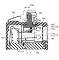
- the switch in the present embodiment when dust or the like enters the area surrounded by the base block 130 and the case 150, a short circuit or poor conduction occurs between the fixed contact 111 and the movable contact 121. Etc. Therefore, when the switch in the present embodiment is OFF, as shown in FIG. 37, in order to prevent the entry of dust and the like into the area surrounded by the base block 130 and the case 150, the opening 151 is formed in the case 150.
- the upper surface of the card main body 145 of the card 140 is in contact with and pressed against the formed inner surface. Thus, dust or the like can be prevented from entering the inside of the case 150 from the opening 151 when the switch is off.
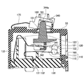
- the switch in the present embodiment when the switch in the present embodiment is on, as shown in FIG. 38, in order to prevent dust and the like from entering the area surrounded by the base block 130 and the case 150, the vicinity of the opening 151 in the case 150 And a U-shaped end portion 162 provided on the button 160 is provided.
- the wall portion 152 of the case 150 is formed so as to cover the U-shaped end portion 162 provided on the button 160, and can be closed by the wall portion 152 and the end portion 162. Thereby, it is possible to prevent dust and the like from entering the inside of the case 150 from the opening 151 when the switch is on.
- the present embodiment has a structure in which a plurality of fixed contacts 111 and a plurality of movable contacts 121 are provided.
- a plurality of electronic devices or electric The power supply to the circuit may be simultaneously turned on or turned off.
- the plurality of fixed contacts 111 and the movable contact 121 can be simultaneously turned on or turned off.
- the switch in the present embodiment has a card 340 having a structure that does not have a rotation axis.
- the button 160 is pressed, the card 340 moves up and down.
- the fixed contact 111 in the fixed part 110 and the movable contact 121 in the movable part 120 are in contact with each other.
- the contact portion 344 a in contact with the inner wall portion 161 of the button 160 is pushed, the card 340 is lowered, and the movable plate portion 122 is moved downward from the upper contact portion 341 in the card 340.
- the fixed contact 111 and the movable contact 121 come into contact with each other. Thereby, as shown in FIG. 41, it is turned on. In this state, as in the second embodiment, the movable contact 121 is kept in contact with the fixed contact 111 by an unillustrated on-state maintaining mechanism or the like.
- the locking or the like in the ON state maintaining mechanism (not shown) is released, and the state is returned to the OFF state as shown in FIG. That is, the movable plate portion 122 is pushed upward from the lower contact portion 342 in the card 340, and the contact between the fixed contact 111 and the movable contact 121 is released. Since the upper contact portion 341 and the lower contact portion 342 slide on the movable plate portion 122, the surface of the upper contact portion 341 and the lower contact portion 342 has a fluororesin or the like in order to reduce frictional resistance. You may provide the surface layer formed by these.
- the switch in this embodiment has a structure in which the card 340 does not have a rotating shaft or the like, the switch can be reduced in size.
- the contents other than the above are the same as in the second embodiment.
- the switch in the present embodiment can be used as a switch section in the connector in the first embodiment.
- FIG. 42 the off state is shown in FIG. 42
- the on state is shown in FIG. 43
- FIG. 44 is a perspective view of the fixed portion 110 and the movable portion 420.
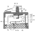
- the switch in this embodiment is formed by a cable 423 in which the movable spring 123 is an electric wire.
- the movable spring 123 since the contact between the fixed contact 111 and the movable contact 121 can be released by the restoring force of the separation spring 170, the movable spring 123 or the like does not require springiness.
- the part corresponding to may be formed by the cable 423.
- Such a cable 423 may be any cable as long as it has conductivity, but a cable such as a knitted wire that can provide flexible movement is preferable. Further, the surface of the cable 423 may be covered. Note that the cable 423 has a conductive portion connected to a terminal connection portion 424 provided in the movable portion 420.
- the contents other than those described above are the same as those in the second or third embodiment.
- the switch in the present embodiment can be used as a switch section in the connector in the first embodiment.
Landscapes
- Physics & Mathematics (AREA)
- Electromagnetism (AREA)
- Details Of Connecting Devices For Male And Female Coupling (AREA)
- Slide Switches (AREA)
Abstract
他のコネクタにおける他の接続端子と接続される接続端子と、固定接点と、可動板部の一方の端部に設けられた可動接点と、絶縁体により形成されており、可動板部と接触するカードと、カードと接触するボタンと、ボタンに接続された開離バネと、固定接点と可動接点との接触を制御するためのスライド操作部と、を有し、固定接点または可動接点のうち、いずれか一方は接続端子と接続されているものであって、スライド操作部を一方の方向に移動させることにより、ボタンが押下され、カードを介して可動板部が動き、固定接点と可動接点とが接触することによりオン状態となり、開離バネは、オン状態より固定接点と可動接点との接触を離す方向に復元力が働くものであって、スライド操作部を一方の方向とは反対方向である他方の方向に移動させることによって、開離バネの復元力により固定接点と可動接点との接触が離れ、オフ状態となるコネクタを提供する。
Description
本発明は、コネクタ及びスイッチに関する。
一般的に電気機器は、電源等より電力の供給を受け動作するものであり、通常、コネクタを介し電源より電気機器へ電力が供給される。この際一例として特許文献1、2に開示されているように、凸状の雄型タイプのコネクタと、凹状の雌型タイプのコネクタを嵌合することにより、電気的に接続が行われる。
一方、近年では、地球温暖化等に対する対策の一つとして、ローカルエリアでの送電においても、電圧変換や送電等における電力損失が少なく、ケーブルの太さも太くする必要のない、直流で高電圧の電力の供給が検討されている。特に、サーバ等の情報機器においては、大量に電力を消費するためこのような電力供給が望ましい場合がある。
ところで、電気機器に供給される電力に関しては、電圧が高いと人体に影響を及ぼす場合や、電子部品の動作に影響を与える場合がある。
このような高電圧の電力をサーバ等の情報機器に用いる場合、装置の設置やメンテナンスの際においては、電気的接続がされている部分であるコネクタは通常の交流の商用電源に対するよりも人体への影響や、電子部品の動作への影響を考慮する必要がある場合がある。
例えば、スイッチを組み込んだ構成のコネクタでは、電源から供給される電圧が100V以上の場合、または、高電圧で直流である場合、現在使用されているスイッチをそのまま用いることはできない。電源から供給される電力が直流400Vの場合では、現在の交流100Vに用いられているスイッチでは、十分な安全性や信頼性が確保されていないため、そのまま使用することは危険な場合がある。
よって、本発明は、上記に鑑みてなされたものであり、高電圧の電力を安全に供給することが可能なコネクタを提供することを目的とするものであり、更には、現状の商用電源の電圧よりも高い電圧の電源、または、直流電源に対応したスイッチであって、安全性及び信頼性の高いスイッチを提供することを目的とするものである。
本発明を実施するための形態によれば、他のコネクタにおける他の接続端子と接続される接続端子と、固定接点と、可動板部の一方の端部に設けられた可動接点と、絶縁体により形成されており、前記可動板部と接触するカードと、前記カードと接触するボタンと、前記ボタンに接続された開離バネと、前記固定接点と前記可動接点との接触を制御するためのスライド操作部と、を有し、前記固定接点または前記可動接点のうち、いずれか一方は前記接続端子と接続されているものであって、前記スライド操作部を一方の方向に移動させることにより、前記ボタンが押下され、前記カードを介して前記可動板部が動き、前記固定接点と前記可動接点とが接触することによりオン状態となり、前記開離バネは、前記オン状態より前記固定接点と前記可動接点との接触を離す方向に復元力が働くものであって、前記スライド操作部を前記一方の方向とは反対方向である他方の方向に移動させることによって、前記開離バネの復元力により前記固定接点と前記可動接点との接触が離れ、オフ状態となることを特徴とする。
また、本発明を実施するための形態によれば、前記ボタンの上面には、高さが低く形成された下段部と、高さが高く形成された上段部と、前記底面部と前記上段部につながる傾斜部が設けられており、前記スライド操作部の動作に対応して動作するコンタクトスライド部が設けられており、前記オフ状態では、前記ボタンの前記底面部に前記コンタクトスライド部の先端が接触しており、前記オン状態では、前記ボタンの前記上段部に前記コンタクトスライド部の先端が接触することにより、前記ボタンが押下されるものであることを特徴とする。
また、本発明を実施するための形態によれば、前記コンタクトスライド部には、コンタクトスライド開口部と前記ボタンと接触するコンタクトスライド接触部を有しており、前記スライド操作部の動作に対応して動作するスライドリンク部の一部が、前記コンタクトスライド開口部内に入っており、前記スライド操作部をスライドさせることにより、前記スライドリンク部が前記スライド方向と略平行方向に移動し、前記スライドリンク部の一部により前記コンタクトスライド開口部の一方の端部または他方の端部が押されることにより、前記コンタクトスライド部が前記スライド方向と略平行に移動するものであることを特徴とする。
また、本発明を実施するための形態によれば、前記他のコネクタにはコネクタ接続開口部が設けられており、前記オン状態では、前記コネクタ接続開口部にフックが入り込んでいることを特徴とする。
また、本発明を実施するための形態によれば、前記カードには、前記可動板部の一方の面と接触する第1の接触部と、他方の面と接触する第2接触部とを有しているものであることを特徴とする。
また、本発明を実施するための形態によれば、前記固定接点と前記可動接点はスイッチ部ケースとベースブロックとに囲まれた領域内に設置されており、前記開離バネは、前記スイッチ部ケースの外部に設けられているものであることを特徴とする。
また、本発明を実施するための形態によれば、前記ケースには開口部が設けられており、前記カードは、前記ケースと前記ベースブロックとに囲まれた領域の内部に存在するカード本体部と、前記ケースにおける前記開口部より前記ケースの外側に飛び出した形状の突起部とを有しており、オフ状態においては、前記ケースにおける前記開口部と前記カード本体部の上面とが接触するものであることを特徴とする。
また、本発明を実施するための形態によれば、前記ケースにおける前記開口部の近傍には壁部が設けられており、前記ボタンには、オン状態において、前記ケースの壁部を覆うように形成された端部を有していることを特徴とする。
また、本発明を実施するための形態によれば、前記カードは、前記ベースブロックに回転可能な状態で接続されていることを特徴とする。
また、本発明を実施するための形態によれば、前記固定接点は固定バネの一方の端部に設けられており、前記固定バネの他方の端部は前記ベースブロックに接続されており、前記可動板部の他方の端部は可動バネの一方の端部と接続されており、前記可動バネの他方の端部は前記ベースブロックに接続されており、前記固定バネと前記可動バネとの間には絶縁壁が設けられていることを特徴とする。
また、本発明を実施するための形態によれば、前記固定接点と前記可動接点との接触位置の近傍には、永久磁石が設けられていることを特徴とする。
また、本発明を実施するための形態によれば、前記固定接点と、前記可動接点は複数設けられているものであることを特徴とする。
また、本発明を実施するための形態によれば、複数設けられた前記固定接点と前記可動接点は、前記ボタンにより、前記固定接点に対応する前記可動接点が、各々同時に接触するものであることを特徴とする。
また、本発明を実施するための形態によれば、固定接点と、可動板部の一方の端部に設けられた可動接点と、絶縁体により形成されており、前記可動板部と接触するカードと、前記カードと接触するボタンと、前記ボタンに接続された開離バネと、を有し、前記ボタンを押下することにより、前記カードを介して前記可動板部が動き、前記固定接点と前記可動接点とが接触しオン状態となるものであって、前記開離バネは、前記オン状態より前記固定接点と前記可動接点との接触を離す方向に復元力が働くものであることを特徴とする。
また、本発明を実施するための形態によれば、前記カードには、前記可動板部の一方の面と接触する第1の接触部と、他方の面と接触する第2接触部とを有しているものであることを特徴とする。
また、本発明を実施するための形態によれば、前記固定接点と前記可動接点はケースとベースブロックとに囲まれた領域内に設置されており、前記開離バネは、前記ケースの外部に設けられているものであることを特徴とする。
また、本発明を実施するための形態によれば、前記ケースには開口部が設けられており、前記カードは、前記ケースと前記ベースブロックとに囲まれた領域の内部に存在するカード本体部と、前記ケースにおける前記開口部より前記ケースの外側に飛び出た形状の突起部とを有しており、オフ状態においては、前記ケースにおける前記開口部と前記カード本体部の上面とが接触するものであることを特徴とする。
また、本発明を実施するための形態によれば、前記ケースにおける前記開口部の近傍には壁部が設けられており、前記ボタンには、オン状態において、前記ケースの壁部を覆うように形成された端部を有していることを特徴とする。
また、本発明を実施するための形態によれば、前記カードは、前記ベースブロックに回転可能な状態で接続されていることを特徴とする。
また、本発明を実施するための形態によれば、前記固定接点は固定バネの一方の端部に設けられており、前記固定バネの他方の端部は前記ベースブロックに接続されており、前記可動板部の他方の端部は可動バネの一方の端部と接続されており、前記可動バネの他方の端部は前記ベースブロックに接続されており、前記固定バネと前記可動バネとの間には絶縁壁が設けられていることを特徴とする。
また、本発明を実施するための形態によれば、前記可動バネに代えて電線が用いられていることを特徴とする。
また、本発明を実施するための形態によれば、前記固定接点と前記可動接点との接触位置の近傍には、永久磁石が設けられていることを特徴とする。
また、本発明を実施するための形態によれば、前記固定接点と、前記可動接点は複数設けられているものであることを特徴とする。
また、本発明を実施するための形態によれば、複数設けられた前記固定接点と前記可動接点は、前記ボタンにより、前記固定接点に対応する前記可動接点が、各々同時に接触するものであることを特徴とする。
本発明を実施するための形態によれば、現状の商用電源の電圧よりも高い電圧の電源、または、直流電源に対応したコネクタであって、これらの電源からの電力を安全に供給することが可能なコネクタを提供することができ、更には、現状の商用電源の電圧よりも高い電圧の電源、または、直流電源に対応したスイッチであって、安全性及び信頼性の高いスイッチを提供することができる。
本発明を実施するための形態について、以下に説明する。尚、同じ部材等については、同一の符号を付して説明を省略する。
〔第1の実施の形態〕
(コネクタの構造)
第1の実施の形態におけるコネクタの構造について説明する。本実施の形態におけるコネクタは、図1から図5に示される他のコネクタであるプラグコネクタと接続されるものであって、図6から図8に示される構造のジャックコネクタに相当するコネクタである。尚、図1から図5に示されるプラグコネクタと、図6から図8に示されるジャックコネクタに相当するコネクタとをあわせてコネクタと称する場合もある。
(コネクタの構造)
第1の実施の形態におけるコネクタの構造について説明する。本実施の形態におけるコネクタは、図1から図5に示される他のコネクタであるプラグコネクタと接続されるものであって、図6から図8に示される構造のジャックコネクタに相当するコネクタである。尚、図1から図5に示されるプラグコネクタと、図6から図8に示されるジャックコネクタに相当するコネクタとをあわせてコネクタと称する場合もある。
最初に、図1から図5に基づきプラグコネクタ200について説明する。尚、図1は、プラグコネクタ200の斜視図であり、図2は上面図であり、図3は側面図であり、図4は底面図であり、図5は正面図である。このプラグコネクタ200は、絶縁体等により形成されたカバー210と、他の接続端子である3本のプラグ端子221、222、223を有しており、3本のプラグ端子221、222、223が設けられている側と反対側には、電源ケーブル230が接続されている。プラグ端子221はGND端子であり、プラグ端子222、223よりも長く形成されている。プラグ端子222、223は、電気的に接続されることにより電力が供給される端子である。尚、このプラグコネクタ200には、プラグ端子221、222、223の設けられている側のカバー210部分において、プラグ端子221、222、223の一部を覆うような形状で形成された保護部211が設けられており、更には、本第1の実施の形態におけるコネクタと接続された後に、コネクタ接続がはずれることのないようにコネクタ接続開口部212が設けられている。
次に、図6から図8に基づき本実施の形態におけるコネクタについて説明する。尚、図6は、本実施の形態におけるコネクタの斜視図であり、図7は正面図であり、図8は側面図である。本実施の形態におけるコネクタは、全体が筐体50に覆われており、プラグコネクタ200におけるプラグ端子221、222、223が挿入されるジャック開口部21、22、23と、プラグコネクタ200における保護部211が挿入される溝部31と、プラグコネクタ200と本実施の形態におけるコネクタとが接続されている状態で、電力を供給するか否かの制御を行なうためのスライド操作部40が設けられている。スライド操作部40は、「ON」の位置または「OFF」の位置となるように、スライドさせることが可能であり、スライド操作部40をスライドさせることにより、コネクタを介し、電力を供給するか否かの制御を行なうことができる。
より詳細に図9に基づき本実施の形態におけるコネクタの内部構造について説明する。図9は、本実施の形態におけるコネクタの内部構造を示す断面図である。本実施の形態におけるコネクタは、スライド操作部40におけるスライド操作上部40aが筐体50に設けられた開口より外側に突出した形状となっており、筐体50の外側よりスライド操作上部40aを矢印Aで示されるスライド方向に移動させることにより、筐体50の内部におけるスイッチ部100において、電気的な接続を行なうか否かの操作を行なうことができる。
スライド操作部40は筐体50にスライド操作本体部40bを有しており、スライド操作本体部40bは、スライドリンク部41と接続されている。スライドリンク部41は、矢印Aで示されるスライド方向と略平行に動作するものであって、L字状に形成されており、L字状の一方の端は、コンタクトスライド部42のコンタクトスライド開口部42a内に入り込んだ構造となっている。このコンタクトスライド開口部42aは、スライドリンク部41の移動方向、即ち、矢印Aで示されるスライド方向に沿った細長い形状で形成されている。また、後述するように、コンタクトスライド部42には、矢印Aで示されるスライド方向に対し略垂直方向に伸びるコンタクトスライド接触部が設けられており、コンタクトスライド接触部の先端は、スイッチ部100におけるボタン160の上面に接触している。
(スイッチ部)
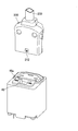
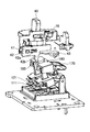
次に、スイッチ部100について説明する。本実施の形態におけるコネクタのスイッチ部100は、電力の供給の制御を行なうためのスイッチであって、電源スイッチとも称される。図10にスイッチ部100の斜視図を示し、図11にスイッチ部100の内部構造図を示す。図11に示されるように、スイッチ部100は、固定部110における固定接点111と可動部120における可動接点121とが接触するか否かにより、電源の供給のオン、オフの制御を行なうことができるものである。
次に、スイッチ部100について説明する。本実施の形態におけるコネクタのスイッチ部100は、電力の供給の制御を行なうためのスイッチであって、電源スイッチとも称される。図10にスイッチ部100の斜視図を示し、図11にスイッチ部100の内部構造図を示す。図11に示されるように、スイッチ部100は、固定部110における固定接点111と可動部120における可動接点121とが接触するか否かにより、電源の供給のオン、オフの制御を行なうことができるものである。
固定部110は、全体が金属等の導電性材料により形成されており、可動部120における可動接点121と接触する固定接点111が、固定バネ112の一方の端部に設けられている構造のものである。尚、固定バネ112は、銅又は銅を含む合金等からなる金属板等を折曲げることにより形成されており、固定接点111は銀と銅の合金により形成されている。固定バネ112の他方の端部はベースブロック130におけるベースブロック本体部131において固定されるとともに、固定バネ112の中程において固定部支持部132において支持され固定されている。
可動部120は、全体が金属等の導電性材料により形成されており、固定部110における固定接点111と接触する可動接点121が、可動板部122の一方の端部に設けられ、可動板部122の他方の端部と可動バネ123の一方の端部とが接続された構造のものである。尚、可動板部122及び可動バネ123は、銅又は銅を含む合金等からなる金属板等を折曲げることにより形成されており、可動接点121は銀と銅の合金により形成されている。可動バネ123の他方の端部はベースブロック130におけるベースブロック本体部131において固定されているが、可動バネ123は金属板等を折曲げることにより形成されているものであるため柔軟性を有しており、可動板部122の一方の端部に設けられた可動接点121を上下方向に動かすことが可能である。また、ベースブロック130には、固定バネ112の他方が接続されている部分と、可動バネ123の他方が接続されている部分との間には、難燃性の樹脂材料等からなる絶縁壁133が設けられており、可動バネ123は、他方の端部より絶縁壁133の周囲の一部を回り込むような形状で曲げられている。
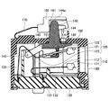
可動部120における可動板部122の一方の面となる上面は、カード140における第1の接触部となる上部接触部141と接触しており、可動板部122の他方の面となる下面は、カード140における第2の接触部となる下部接触部142と接触している。この状態において、カード140を、回転軸143を中心に回転させることにより、可動板部122が上部接触部141または下部接触部142と接触し力が加わり、可動接点121を上下方向に移動させることができる。尚、上部接触部141及び下部接触部142は、可動板部122において摺動するものであるため、摩擦抵抗を低減させるために上部接触部141及び下部接触部142の表面には、フッ素樹脂等により形成された表面層を設けてもよい。
尚、固定部110及び可動部120は、ベースブロック130とスイッチ部ケース150に囲まれた領域の内部に設置されており、カード140は、スイッチ部ケース150に設けられたスイッチ部開口部151より外部に突出した形状の突起部144と、ベースブロック130とスイッチ部ケース150に囲まれた領域の内部に位置するカード本体部145とを有している。従って、スイッチ部100においては、上部接触部141または下部接触部142は、ベースブロック130とスイッチ部ケース150に囲まれた領域の内部に設けられている。また、カード140、ベースブロック130及びスイッチ部ケース150は樹脂材料等からなる絶縁体材料により形成されている。
スイッチ部ケース150の外部には、回転軸143を中心にカード140を回転させるために、押下されるボタン160が設けられており、カード140は、カード140における突起部144の上部に設けられた接触部144aにおいて、ボタン160の内壁部161と接触している。尚、接触部144aは、内壁部161の表面を摺動するものであるため、摩擦抵抗を低減させるために内壁部161の表面には、フッ素樹脂等により形成された表面層を設けてもよい。また、スイッチ部ケース150の外部には、一方の端部がスイッチ部ケース150に接続され、他方の端部がボタン160に接続された開離バネ170が設けられている。
(スイッチ部におけるオン、オフ動作)
スイッチ部100において、スイッチをオンにする場合には、後述するように、コンタクトスライド部42におけるコンタクトスライド接触部を移動させることにより、ボタン160を押下し、ボタン160の内壁部161において接触部141が接触しているカード140が回転軸143を中心に回転する。これにより、上部接触部141を介し可動部120における可動板部122に下方向に力が加えられ、可動接点121と固定接点111とが接触する。この状態を図12に示す。尚、後述するように、スイッチ部100において、この状態はコンタクトスライド部42におけるコンタクトスライド接触部により維持されるため、可動接点121と固定接点111との接触が維持され、電源から電力が供給される。
スイッチ部100において、スイッチをオンにする場合には、後述するように、コンタクトスライド部42におけるコンタクトスライド接触部を移動させることにより、ボタン160を押下し、ボタン160の内壁部161において接触部141が接触しているカード140が回転軸143を中心に回転する。これにより、上部接触部141を介し可動部120における可動板部122に下方向に力が加えられ、可動接点121と固定接点111とが接触する。この状態を図12に示す。尚、後述するように、スイッチ部100において、この状態はコンタクトスライド部42におけるコンタクトスライド接触部により維持されるため、可動接点121と固定接点111との接触が維持され、電源から電力が供給される。
また、スイッチ部100において、スイッチをオフにする場合には、後述するように、コンタクトスライド部42におけるコンタクトスライド接触部を移動させることにより、開離バネ170による復元力により、ボタン160がオフの状態に戻る。即ち、図11に示されるように、ボタン160の内壁部161において接触部141が接触しているカード140が回転軸143を中心に回転し、下部接触部142を介し可動部120における可動板部122に上方向に力が加わる。このように可動板部122に加えられた上方向の力により可動接点121と固定接点111との接触を解除することができ、電源からの電力の供給を停止することができる。この際、可動接点121と固定接点111との間でアークが発生しうるため、磁界の力によりアークを飛ばすことができるように、可動接点121と固定接点111との接触位置の近傍には、アークの発生する方向に対して略垂直方向の磁界を発生させる永久磁石180が設けられている。
スイッチ部100では、電源からの電力の供給を遮断する際には、可動部120における可動バネ123等の復元力を用いるのではなく、スイッチ部ケース150の外部に設けられた開離バネ170の復元力によりオフ状態にするものである。このため、可動部120における可動バネ123等において復元力を有していない場合においても、電源をオフにすることができる。また、熱により可動バネ123等の一部が溶けてしまい、バネとしての機能が失われている場合においても、可動バネ123等の復元力を用いることなく、開離バネ170のバネ性により電源をオフ状態にすることができ、電源からの電力の供給を確実に遮断することができる。また、開離バネ170は、スイッチ部ケース150の外部に設置されているため、スイッチ部ケース150内部において固定部110及び可動部120が受ける可能性のある熱等の影響を受けることはない。
また、スイッチ部100では、ベースブロック130において、固定バネ112の他方が接続されている部分と、可動バネ123の他方が接続されている部分との間には、絶縁壁133が設けられている。これにより、固定部110と可動部120との熱による溶解等が進行した場合においても、固定部110の溶解された部分と、可動部120の溶解された部分とが絶縁壁133により分離される。よって、固定部110と可動部120とが溶解し、くっついた状態のまま電流が流れ続けてしまうことを防ぐことができる。
尚、スイッチ部100では、ゴミ等がベースブロック130とケース150に囲まれた領域に侵入した場合には、固定接点111と可動接点121との間でショートまたは接触不良となる場合等がある。従って、スイッチ部100がオフの状態においては、ベースブロック130とケース150に囲まれた領域へのゴミ等の侵入を防ぐため、ケース150における開口部151を塞ぐようにカード140のカード本体部145の上面が接触して押し当てられるように形成されている。これにより、スイッチ部100がオフ状態において、開口部151からケース150の内部にゴミ等が侵入することを防ぐことができる。
また、スイッチ部100がオンの状態においては、ベースブロック130とケース150に囲まれた領域へのゴミ等の侵入を防ぐため、ケース150における開口部151近傍に設けられた壁部152と、ボタン160に設けられたU字状の端部162が設けられている。スイッチ部100がオン状態においては、ケース150における壁部152をボタン160に設けられたU字状の端部162が覆うように形成されており、壁部152と端部162により塞ぐことができる。これにより、スイッチ部100がオン状態において、開口部151からケース150の内部にゴミ等が侵入することを防ぐことができる。
(コネクタにおけるオン、オフ動作)
次に、本実施の形態におけるコネクタにおけるオン、オフ動作について説明する。本実施の形態におけるコネクタとプラグコネクタ200とが接続されている状態において、本実施の形態におけるコネクタにおけるオン、オフの制御を行なうことにより、スイッチ部100のオン、オフを行なうことができ、電源等からの電力の供給の制御を行なうことができる。
次に、本実施の形態におけるコネクタにおけるオン、オフ動作について説明する。本実施の形態におけるコネクタとプラグコネクタ200とが接続されている状態において、本実施の形態におけるコネクタにおけるオン、オフの制御を行なうことにより、スイッチ部100のオン、オフを行なうことができ、電源等からの電力の供給の制御を行なうことができる。
最初に、図13に示されるように本実施の形態におけるコネクタとプラグコネクタ200とが接続されていない状態から、図14に示されるように、本実施の形態におけるコネクタとプラグコネクタ200とを接続する。この状態では、本実施の形態におけるコネクタのスライド操作部40のスライド操作上部40aが「OFF」の位置のままでありオフ状態にあるため、電気的には接続はされておらず、コネクタを介し電力等が供給されることはない。次に、図15に示されるように、本実施の形態におけるコネクタのスライド操作部40のスライド操作上部40aを「ON」の位置までスライドさせてON状態にする。これにより本実施の形態におけるコネクタとプラグコネクタ200とが電気的に接続されコネクタを介し電力等が供給される。以下、本実施の形態におけるコネクタにおいて、図14に示すオフ状態から図15に示すオン状態になるまでの状況をより詳しく説明する。
次に、図14に示されるオフ状態について、図16から図20に基づき説明する。図16は、オフ状態における本実施の形態におけるコネクタの側面側から見た内部構造図であり、図17は、正面側から見た内部構造図であり、図18は、内部構造の要部の斜視図であり、図19は、機構部分の要部の斜視図であり、図20は、内部構造の要部の側面図である。オフ状態においては、スライド操作上部40aが「OFF」の位置にあるため、コンタクトスライド部42におけるコンタクトスライド開口部42aの左側に、L字状に形成されたスライドリンク部41の一方が接触している状態となっている。また、トーションバネ43の一方は筐体50の一部に接続されており、他方はスライド操作部40に接続されている。また、図21に示されるように、コンタクトスライド部42には、矢印Aに示されるスライド方向に対し略垂直方向に伸びるコンタクトスライド接触部42b設けられており、スイッチ部160の上面に設けられた溝の下段部163において、コンタクトスライド接触部42bの先端が接触している。
尚、本実施の形態におけるコネクタのジャック開口部21、22、23の内部には、プラグ端子221、222、223と電気的に接続されるジャック端子61、62、63が設けられており、前述したスイッチ部100には、固定部110及び可動部120はジャック端子62及び63に対応して2対設けられている。即ち、ジャック端子62は、一方の1対の固定部110または可動部120のいずれか一方に接続されており、他方は不図示の電源供給源に接続されている。また、ジャック端子63は、他方の1対の固定部110または可動部120のいずれか一方に接続されており、他方は不図示の電源供給源に接続されている。更に、図22に示されるフック70は、スライド操作部40の側面の幅狭部40cと接しており、この状態においては、フック70はプラグコネクタ200におけるコネクタ接続開口部212に入ってはいないため、本実施の形態におけるコネクタとプラグコネクタ200との脱着は可能な状態にある。
次に、スライド操作部40をオフ状態とオン状態の略中間の位置まで移動させた場合について、図23から図25に基づき説明する。図23は、この状態における本実施の形態におけるコネクタの側面側から見た内部構造図であり、図24は、機構部分の要部の斜視図であり、図25は、内部構造の要部の側面図である。この状態においては、スライド操作上部40aは、「ON」の位置と「OFF」の位置の略中間の位置にあり、コンタクトスライド部42におけるコンタクトスライド開口部42aの右側において、L字状に形成されたスライドリンク部41の一方の端が接触して、コンタクトスライド部42をスライド方向に若干移動させる。これにより、コンタクトスライド部42におけるコンタクトスライド接触部42bの先端は、図21に示されるスイッチ部160に設けられた溝の傾斜部164において接触している状態となる。尚、この状態においては、固定部110における固定接点111と可動部120における可動接点121とは接触していない。
次に、図15に示されるオン状態について、図26から図30に基づき説明する。図26は、この状態における本実施の形態におけるコネクタの側面側から見た内部構造図であり、図27は、正面側から見た内部構造図であり、図28は、内部構造の要部の斜視図であり、図29は、機構部分の要部の斜視図であり、図30は、内部構造の要部の側面図である。オン状態においては、スライド操作上部40aは、「ON」の位置にあり、コンタクトスライド部42におけるコンタクトスライド開口部42aの右側をL字状に形成されたスライドリンク部41の一方が更に押されることにより、コンタクトスライド部42を更に移動させることができる。これによりコンタクトスライド部42におけるコンタクトスライド接触部42bの先端は、スイッチ部160に設けられた上段部165において接触する。この状態においては、スイッチ部100におけるボタン160がコンタクトスライド接触部42bにより押されるため、2対の固定部110における固定接点111と可動部120における可動接点121とが各々接触する。このオン状態は、スイッチ部160に設けられた上段部165にコンタクトスライド部42におけるコンタクトスライド接触部42bの先端が接触していることにより維持される。
また、オフ状態からオン状態に変化する際には、図22に示されるフック70におけるスライド操作部40の側面との接触位置は、スライド操作部40の側面の幅狭部40cから、傾斜部40dを経て、幅広部40eに移動するため、矢印A1で示されるスライド操作上部40aのスライド方向にスライドさせることにより、スライド方向に対し略垂直方向である矢印B1に示される方向に移動する。移動したフック70は、プラグコネクタ200に設けられたコネクタ接続開口部212内に入り込み嵌合するため、本実施の形態におけるコネクタとプラグコネクタとの接続が維持される。
尚、オン状態からオフ状態に移行する場合には、本実施の形態におけるコネクタのスライド操作上部40aの位置を「ON」の位置から「OFF」の位置にスライドさせることにより行なう。このようにスライド操作上部40aの位置をスライドさせることにより、コンタクトスライド部42におけるコンタクトスライド接触部42bの先端が接触している位置が、スイッチ部160に設けられた上段部165から傾斜部164を経て下段部163に移動する。これにより、スイッチ部160が開離バネ170により持ち上げられ、2対の固定部110における固定接点111と可動部120における可動接点121との接触が離れオフ状態となる。この際、図22に示されるフック70におけるスライド操作部40の側面との接触位置は、スライド操作部40の側面の幅広部40eから、傾斜部40dを経て、幅狭部40cに移動する。これにより、プラグコネクタ200におけるコネクタ接続開口部212内よりフック70が外に出るため、本実施の形態におけるコネクタよりプラグコネクタ200をはずすことが可能となる。
〔第2の実施の形態〕
次に、第2の実施の形態におけるスイッチについて説明する。本実施の形態におけるスイッチは、第1の実施の形態におけるコネクタにおいてスイッチ部に相当するものであり、本実施の形態においてより詳細に説明する。
次に、第2の実施の形態におけるスイッチについて説明する。本実施の形態におけるスイッチは、第1の実施の形態におけるコネクタにおいてスイッチ部に相当するものであり、本実施の形態においてより詳細に説明する。
最初に、電源より供給される電圧が100V以上の場合における電源スイッチについて説明する。
電源より供給される電圧が100V以上、例えば、直流400Vの場合において、現在市販されているスイッチを用いた場合には、電圧が高電圧であること、また、直流であることにより、何らかの原因によって接触している接点同士が熱等により溶けてくっついてしまい、電力の供給を遮断することができなくなってしまう場合がある。このことはスイッチとしての機能を完全に失わせるものであり、影響も大きいため、スイッチとして問題である。
(スイッチ)
次に、本実施の形態におけるスイッチについて説明する。本実施の形態におけるスイッチは、電力の供給の制御を行なうためのスイッチであって、電源スイッチとも称される。図31に示されるように、本実施の形態におけるスイッチは、固定部110における固定接点111と可動部120における可動接点121とが接触するか否かにより、電源の供給のオン、オフの制御をすることができるものである。
次に、本実施の形態におけるスイッチについて説明する。本実施の形態におけるスイッチは、電力の供給の制御を行なうためのスイッチであって、電源スイッチとも称される。図31に示されるように、本実施の形態におけるスイッチは、固定部110における固定接点111と可動部120における可動接点121とが接触するか否かにより、電源の供給のオン、オフの制御をすることができるものである。
固定部110は、全体が金属等の導電性材料により形成されており、可動部120における可動接点121と接触する固定接点111が、固定バネ112の一方の端部に設けられている構造のものである。尚、固定バネ112は、銅又は銅を含む合金等からなる金属板等を折曲げることにより形成されており、固定接点111は銀と銅の合金により形成されている。固定バネ112の他方の端部はベースブロック130におけるベースブロック本体部131において固定されるとともに、固定バネ112の中程において固定部支持部132において支持され固定されている。
可動部120は、全体が金属等の導電性材料により形成されており、固定部110における固定接点111と接触する可動接点121が、可動板部122の一方の端部に設けられており、可動板部122の他方の端部と可動バネ123の一方の端部とが接続された構造のものである。尚、可動板部122及び可動バネ123は、銅又は銅を含む合金等からなる金属板等により形成されており、可動接点121は銀と銅の合金により形成されている。可動バネ123の他方の端部はベースブロック130におけるベースブロック本体部131において固定されているが、可動バネ123は金属板等を折曲げることにより形成されているものであるため柔軟性を有しており、可動板部122の一方の端部に設けられた可動接点121を上下方向に動かすことが可能である。また、ベースブロック130には、固定バネ112の他方が接続されている部分と、可動バネ123の他方が接続されている部分との間には、難燃性の樹脂材料等からなる絶縁壁133が設けられており、可動バネ123は、他方の端部より絶縁壁133の周囲の一部を回り込むような形状で曲げられている。
可動部120における可動板部122の一方の面となる上面は、カード140における第1の接触部となる上部接触部141と接触しており、可動板部122の他方の面となる下面は、カード140における第2の接触部となる下部接触部142と接触している。この状態において、カード140が回転軸143を中心に回転することにより、可動板部122と接触している上部接触部141または下部接触部142を介して力が加わり、可動接点121を上下方向に移動させることができる。尚、上部接触部141及び下部接触部142は、可動板部122において摺動するものであるため、摩擦抵抗を低減させるために上部接触部141及び下部接触部142の表面には、フッ素樹脂等により形成された表面層を設けてもよい。
尚、固定部110及び可動部120は、ベースブロック130とケース150に囲まれた領域の内部に設置されており、カード140は、ケース150に設けられた開口部151より外部に飛び出した形状の突起部144と、ベースブロック130とケース150に囲まれた領域の内部に位置するカード本体部145とを有している。従って、本実施の形態におけるスイッチにおいては、上部接触部141または下部接触部142は、ベースブロック130とケース150に囲まれた領域の内部に設けられている。また、カード140、ベースブロック130及びケース150は樹脂材料等からなる絶縁体材料により形成されている。
ケース150の外部には、回転軸143を中心にカード140を回転させるために、押下されるボタン160が設けられており、カード140は、カード140における突起部144の上部に設けられた接触部144aにおいて、ボタン160の内壁部161と接触している。尚、接触部144aは、内壁部161の表面を摺動するものであるため、摩擦抵抗を低減させるために内壁部161の表面には、フッ素樹脂等により形成された表面層を設けてもよい。また、ケース150の外部には、一方の端部がケース150に接続され、他方の端部がボタン160に接続された開離バネ170が設けられている。
(オン、オフ動作)
本実施の形態におけるスイッチにおいて、スイッチをオンにする場合には、ボタン160を押下することにより、ボタン160の内壁部161と接触部144aにおいて接触しているカード140が回転軸143を中心に回転し、上部接触部141により可動部120における可動板部122に下方向に力が加えられ、可動接点121が固定接点111と接触する。この状態を図32に示す。尚、本実施の形態におけるスイッチでは、この状態を維持するための係止部等を有する不図示のオン状態維持機構等が設けられており、オン状態維持機構等により、可動接点121が固定接点111と接触が維持され、電源から電力の供給が維持される。
本実施の形態におけるスイッチにおいて、スイッチをオンにする場合には、ボタン160を押下することにより、ボタン160の内壁部161と接触部144aにおいて接触しているカード140が回転軸143を中心に回転し、上部接触部141により可動部120における可動板部122に下方向に力が加えられ、可動接点121が固定接点111と接触する。この状態を図32に示す。尚、本実施の形態におけるスイッチでは、この状態を維持するための係止部等を有する不図示のオン状態維持機構等が設けられており、オン状態維持機構等により、可動接点121が固定接点111と接触が維持され、電源から電力の供給が維持される。
また、本実施の形態におけるスイッチにおいて、スイッチをオフにする場合には、不図示のオン状態維持機構等における係止部の係止等がはずれ、開離バネ170のバネ性による復元力により、スイッチをオフにすることができる。これにより図31に示されるように、ボタン160の内壁部161と接触部144aにおいて接触しているカード140が回転軸143を中心に回転し、下部接触部142により可動部120における可動板部122に上方向に力が加えられる。このように可動板部122に加えられた上方向の力により可動接点121と固定接点111との接触を解除でき、電源からの電力の供給を停止することができる。この際、可動接点121と固定接点111との間でアークが発生する場合があるため、磁界の力によりアークを飛ばすことができるように、可動接点121と固定接点111との接触位置の近傍には、アークの発生する方向に対して略垂直方向の磁界を発生させる永久磁石180が設けられている。
本実施の形態におけるスイッチでは、電源をオフする際に、可動部120における可動バネ123等におけるバネの復元力を用いるのではなく、ケース150の外部に設けられた開離バネ170のバネの復元力によりオフ状態にするものである。このため、可動部120における可動バネ123等において復元力を有していない場合においても、電源をオフにすることができる。例えば、熱により可動バネ123等の一部が溶けてしまい、バネとしての機能が失われている場合においても、可動バネ123等における復元力を用いることなく、開離バネ170のバネ性により電源をオフ状態にすることができ、電源からの電力の供給を確実に遮断することができる。また、開離バネ170は、ケース150の外部に設置されているため、ケース150内部において固定部110及び可動部120が受ける熱等の影響を受けることはない。
また、本実施の形態におけるスイッチでは、ベースブロック130において、固定バネ112の他方が接続されている部分と、可動バネ123の他方が接続されている部分との間には、絶縁壁133が設けられている。これにより固定部110と可動部120との熱による溶解が進行した場合においても、絶縁壁133により固定部110の溶解された部分と、可動部120の溶解された部分とが分離され、固定部110と可動部120とが溶解しくっついた状態のまま電流が流れ続けるといった状態となることを防ぐことができる。
(スイッチの組立方法の説明)
次に、本実施の形態におけるスイッチの組立方法において要点となる部分について説明する。
次に、本実施の形態におけるスイッチの組立方法において要点となる部分について説明する。
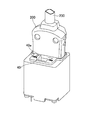
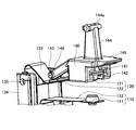
最初に、本実施の形態におけるスイッチにおいて、可動部120とベースブロック130とカード140の接続方法について、図33に基づき説明する。カード140には、回転軸143を中心とする円形状の回転部146が設けられている。また、ベースブロック130にはカード140を接続するためのカード支持部134が設けられており、カード支持部134にはカード140の回転部146が挿入されるように、円形の形状の開口部135が設けられている。回転部146を開口部135内に挿入することにより、カード140は、カード支持部134と回転軸143を中心に回転可能な状態で接続される。また、カード140は、可動板部122の上側に上部接触部141が接し、下側に下部接触部142が接触した状態で、可動板部122に沿って入れられ、回転部146が開口部135内に挿入された状態となるまで入れられ組み立てられる。これにより、可動部120とベースブロック130とカード140とを接続することができる。
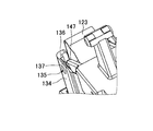
より詳細に、図34及び図35に基づきベースブロック130とカード140との接続について説明する。カード140の回転部146は2本の棒状部147の端部に各々設けられており、各々の回転部146が外側となるように設けられている。ベースブロック130とカード140とを接続する際には、2つの棒状部147を内側方向に曲げることにより、回転部146をベースブロック部130の開口部135に挿入する。尚、開口部135と回転部146との接触する部分には、摩擦抵抗が少なくなるように鏡面処理等が施されている。
また、カード140の回転部146をより滑らかにベースブロック部130の開口部135に挿入するために、カード支持部134には、挿入方向に沿ったガイド136が設けられており、更に、カード支持部134において回転部146が入り込む部分の端部には傾斜部137が設けられている。
尚、上記説明では、可動板部122はカード140における上部接触部141と下部接触部142により挟まれた構造のものについて説明したが、図36に示されるように、可動板部122にT字状の開口部122aを設け、カード140aには、上部接触部141及び下部接触部142に代えて、突起状接続部148を設けた構造のものであってもよい。この突起状接続部148は、端部に尖った形状の先端部148aと、先端部148aに繋がる幅が狭くなった形状の幅狭部148bと、幅狭部148bに繋がる幅が広くなった形状の本体部148cを有している。可動板部122とカード140aとを固定する際には、可動板部122に設けられた開口部122aに、突起状接続部148の先端部148a及び幅狭部148bを挿入することにより固定する。この状態においては、可動板部122の下面は、幅狭部148bと幅が広くなっている先端部148aとの間で固定され、可動板部122の上面は、幅狭部148bと幅が広くなっている本体部148cとの間で固定される。
また、本実施の形態におけるスイッチでは、ゴミ等がベースブロック130とケース150に囲まれた領域に侵入した場合には、固定接点111と可動接点121との間でショートまたは導通不良が発生する場合等がある。従って、本実施の形態におけるスイッチがオフの状態では、図37に示されるように、ベースブロック130とケース150に囲まれた領域へのゴミ等の侵入を防ぐため、ケース150において開口部151が形成されている内側の面に、カード140のカード本体部145の上面が接触し押し当てられるように形成されている。これによりスイッチがオフ状態の場合において、開口部151からケース150の内部にゴミ等が侵入することを防ぐことができる。
また、本実施の形態におけるスイッチがオンの状態では、図38に示されるように、ベースブロック130とケース150に囲まれた領域へのゴミ等の侵入を防ぐため、ケース150における開口部151近傍に設けられた壁部152と、ボタン160に設けられたU字状の端部162が設けられている。スイッチがオン状態においては、ケース150における壁部152をボタン160に設けられたU字状の端部162が覆うように形成されており、壁部152と端部162により塞ぐことができる。これにより、スイッチがオン状態の場合において、開口部151からケース150の内部にゴミ等が侵入することを防ぐことができる。
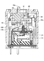
また、図39に示すように、本実施の形態は、固定接点111及び可動接点121が複数設けられた構造のものであって、1つのボタン168を操作することにより、複数の電子機器または電気回路への電力供給を同時にオン状態にしたり、オフ状態にしたりするものであってもよい。これにより複数の固定接点111と可動接点121とを同時にオン状態にしたり、オフ状態にしたりすることができる。
〔第3の実施の形態〕
次に、第3の実施の形態におけるスイッチについて説明する。本実施の形態におけるスイッチにおいて、オフ状態を図40に示し、オン状態を図41に示す。
次に、第3の実施の形態におけるスイッチについて説明する。本実施の形態におけるスイッチにおいて、オフ状態を図40に示し、オン状態を図41に示す。
本実施の形態におけるスイッチは、図40及び図41に示されるように、回転軸を有しない構造のカード340を有するものであって、ボタン160を押下することにより、カード340が上下方向に移動し、固定部110における固定接点111と可動部120における可動接点121とが接触する構造のものである。
具体的には、ボタン160を押下することにより、ボタン160の内壁部161と接している接触部344aが押されカード340が下がり、カード340における上部接触部341より可動板部122が下方向に押され、固定接点111と可動接点121とが接触する。これにより、図41に示されるようにオン状態となる。尚、この状態においては、第2の実施の形態と同様に、不図示のオン状態維持機構等により、可動接点121が固定接点111と接触が維持される。
また、不図示のオン状態維持機構等における係止等がはずれ、開離バネ170による復元力により図40に示されるようにオフ状態に戻る。即ち、カード340における下部接触部342より可動板部122が上方向に押され、固定接点111と可動接点121との接触が離れる。尚、上部接触部341及び下部接触部342は、可動板部122において摺動するものであるため、摩擦抵抗を低減させるために上部接触部341及び下部接触部342の表面には、フッ素樹脂等により形成された表面層を設けてもよい。
本実施の形態におけるスイッチでは、カード340に回転軸等を有していない構造のものであるため、スイッチを小型にすることができる。
尚、上記以外の内容については、第2の実施の形態と同様である。本実施の形態におけるスイッチは、第1の実施の形態におけるコネクタにおけるスイッチ部として用いることが可能である。
〔第4の実施の形態〕
次に、第4の実施の形態におけるスイッチについて説明する。本実施の形態におけるスイッチにおいて、オフ状態を図42に示し、オン状態を図43に示し、図44には、固定部110と可動部420の斜視図を示す。
次に、第4の実施の形態におけるスイッチについて説明する。本実施の形態におけるスイッチにおいて、オフ状態を図42に示し、オン状態を図43に示し、図44には、固定部110と可動部420の斜視図を示す。
本実施の形態におけるスイッチは、第2の実施の形態及び第3の実施の形態において、可動バネ123の部分が電線であるケーブル423により形成されているものである。本実施の形態におけるスイッチでは、開離バネ170の復元力により、固定接点111と可動接点121との接触を離すことができるため、可動バネ123等においてバネ性は必要とされないため、可動バネ123に相当する部分をケーブル423により形成したものであってもよい。このようなケーブル423は導電性を有するものであれば、どのようなものでもよいが、柔軟な動きが得られる編み線等のケーブルが好ましい。また、ケーブル423の表面には被覆がされているものであってもよい。尚、ケーブル423は、導電性を有する部分が、可動部420に設けられた端子接続部424において接続されている。
尚、上記以外の内容については、第2または第3の実施の形態と同様である。本実施の形態におけるスイッチは、第1の実施の形態におけるコネクタにおけるスイッチ部として用いることが可能である。
以上本発明の好ましい実施例について詳述したが、本発明は係る特定の実施形態に限定されるものではなく、特許請求の範囲に記載された本発明の要旨の範囲内において、種々の変形、変更が可能である。
本国際出願は、2010年11月12日に出願した日本国特許出願2010-254259号に基づく優先権を主張するものであり、2010-254259号の全内容をここに本国際出願に援用する。
21 ジャック開口部
22 ジャック開口部
23 ジャック開口部
31 溝部
40 スライド操作部
40a スライド操作上部
40b スライド操作本体部
41 スライドリンク部
42 コンタクトスライド部
42a コンタクトスライド開口部
42b コンタクトスライド接触部
50 筐体
61 ジャック端子
62 ジャック端子
63 ジャック端子
70 フック
110 固定部
111 固定接点
112 固定バネ
120 可動部
121 可動接点
122 可動板部
123 可動バネ
130 ベースブロック
131 ベースブロック本体部
132 固定部支持部
133 絶縁壁
140 カード
141 上部接触部(第1の接触部)
142 下部接触部(第2の接触部)
143 回転軸
144 突起部
144a 接触部
145 カード本体部
150 スイッチ部ケース
151 スイッチ部開口部
152 壁部
160 ボタン
161 内壁部
162 端部
163 底面部
164 傾斜部
165 上段部
170 開離バネ
180 永久磁石
200 プラグコネクタ
210 カバー
211 保護部
212 コネクタ接続開口部
221 プラグ端子
222 プラグ端子
223 プラグ端子
230 電源ケーブル
22 ジャック開口部
23 ジャック開口部
31 溝部
40 スライド操作部
40a スライド操作上部
40b スライド操作本体部
41 スライドリンク部
42 コンタクトスライド部
42a コンタクトスライド開口部
42b コンタクトスライド接触部
50 筐体
61 ジャック端子
62 ジャック端子
63 ジャック端子
70 フック
110 固定部
111 固定接点
112 固定バネ
120 可動部
121 可動接点
122 可動板部
123 可動バネ
130 ベースブロック
131 ベースブロック本体部
132 固定部支持部
133 絶縁壁
140 カード
141 上部接触部(第1の接触部)
142 下部接触部(第2の接触部)
143 回転軸
144 突起部
144a 接触部
145 カード本体部
150 スイッチ部ケース
151 スイッチ部開口部
152 壁部
160 ボタン
161 内壁部
162 端部
163 底面部
164 傾斜部
165 上段部
170 開離バネ
180 永久磁石
200 プラグコネクタ
210 カバー
211 保護部
212 コネクタ接続開口部
221 プラグ端子
222 プラグ端子
223 プラグ端子
230 電源ケーブル
Claims (24)
- 他のコネクタにおける他の接続端子と接続される接続端子と、
固定接点と、
可動板部の一方の端部に設けられた可動接点と、
絶縁体により形成されており、前記可動板部と接触するカードと、
前記カードと接触するボタンと、
前記ボタンに接続された開離バネと、
前記固定接点と前記可動接点との接触を制御するためのスライド操作部と、
を有し、
前記固定接点または前記可動接点のうち、いずれか一方は前記接続端子と接続されているものであって、
前記スライド操作部を一方の方向に移動させることにより、前記ボタンが押下され、前記カードを介して前記可動板部が動き、前記固定接点と前記可動接点とが接触することによりオン状態となり、
前記開離バネは、前記オン状態より前記固定接点と前記可動接点との接触を離す方向に復元力が働くものであって、
前記スライド操作部を前記一方の方向とは反対方向である他方の方向に移動させることによって、前記開離バネの復元力により前記固定接点と前記可動接点との接触が離れ、オフ状態となることを特徴とするコネクタ。
- 前記ボタンの上面には、高さが低く形成された下段部と、高さが高く形成された上段部と、前記底面部と前記上段部につながる傾斜部が設けられており、
前記スライド操作部の動作に対応して動作するコンタクトスライド部が設けられており、
前記オフ状態では、前記ボタンの前記底面部に前記コンタクトスライド部の先端が接触しており、
前記オン状態では、前記ボタンの前記上段部に前記コンタクトスライド部の先端が接触することにより、前記ボタンが押下されるものであることを特徴とする請求項1に記載のコネクタ。
- 前記コンタクトスライド部には、コンタクトスライド開口部と前記ボタンと接触するコンタクトスライド接触部を有しており、
前記スライド操作部の動作に対応して動作するスライドリンク部の一部が、前記コンタクトスライド開口部内に入っており、
前記スライド操作部をスライドさせることにより、前記スライドリンク部が前記スライド方向と略平行方向に移動し、前記スライドリンク部の一部により前記コンタクトスライド開口部の一方の端部または他方の端部が押されることにより、前記コンタクトスライド部が前記スライド方向と略平行に移動するものであることを特徴とする請求項1に記載のコネクタ。
- 前記他のコネクタにはコネクタ接続開口部が設けられており、
前記オン状態では、前記コネクタ接続開口部にフックが入り込んでいることを特徴とする請求項1に記載のコネクタ。
- 前記カードには、前記可動板部の一方の面と接触する第1の接触部と、他方の面と接触する第2接触部とを有しているものであることを特徴とする請求項1に記載のコネクタ。
- 前記固定接点と前記可動接点はスイッチ部ケースとベースブロックとに囲まれた領域内に設置されており、
前記開離バネは、前記スイッチ部ケースの外部に設けられているものであることを特徴とする請求項1に記載のコネクタ。
- 前記ケースには開口部が設けられており、
前記カードは、前記ケースと前記ベースブロックとに囲まれた領域の内部に存在するカード本体部と、前記ケースにおける前記開口部より前記ケースの外側に飛び出した形状の突起部とを有しており、
オフ状態においては、前記ケースにおける前記開口部と前記カード本体部の上面とが接触するものであることを特徴とする請求項6に記載のコネクタ。
- 前記ケースにおける前記開口部の近傍には壁部が設けられており、
前記ボタンには、オン状態において、前記ケースの壁部を覆うように形成された端部を有していることを特徴とする請求項7に記載のコネクタ。
- 前記カードは、前記ベースブロックに回転可能な状態で接続されていることを特徴とする請求項1に記載のコネクタ。
- 前記固定接点は固定バネの一方の端部に設けられており、前記固定バネの他方の端部は前記ベースブロックに接続されており、
前記可動板部の他方の端部は可動バネの一方の端部と接続されており、前記可動バネの他方の端部は前記ベースブロックに接続されており、
前記固定バネと前記可動バネとの間には絶縁壁が設けられていることを特徴とする請求項1に記載のコネクタ。
- 前記固定接点と前記可動接点との接触位置の近傍には、永久磁石が設けられていることを特徴とする請求項1に記載のコネクタ。
- 前記固定接点と、前記可動接点は複数設けられているものであることを特徴とする請求項1に記載のコネクタ。
- 複数設けられた前記固定接点と前記可動接点は、前記ボタンにより、前記固定接点に対応する前記可動接点が、各々同時に接触するものであることを特徴とする請求項12に記載のコネクタ。
- 固定接点と、
可動板部の一方の端部に設けられた可動接点と、
絶縁体により形成されており、前記可動板部と接触するカードと、
前記カードと接触するボタンと、
前記ボタンに接続された開離バネと、
を有し、
前記ボタンを押下することにより、前記カードを介して前記可動板部が動き、前記固定接点と前記可動接点とが接触しオン状態となるものであって、
前記開離バネは、前記オン状態より前記固定接点と前記可動接点との接触を離す方向に復元力が働くものであることを特徴とするスイッチ。
- 前記カードには、前記可動板部の一方の面と接触する第1の接触部と、他方の面と接触する第2接触部とを有しているものであることを特徴とする請求項14に記載のスイッチ。
- 前記固定接点と前記可動接点はケースとベースブロックとに囲まれた領域内に設置されており、
前記開離バネは、前記ケースの外部に設けられているものであることを特徴とする請求項14に記載のスイッチ。
- 前記ケースには開口部が設けられており、
前記カードは、前記ケースと前記ベースブロックとに囲まれた領域の内部に存在するカード本体部と、前記ケースにおける前記開口部より前記ケースの外側に飛び出た形状の突起部とを有しており、
オフ状態においては、前記ケースにおける前記開口部と前記カード本体部の上面とが接触するものであることを特徴とする請求項16に記載のスイッチ。
- 前記ケースにおける前記開口部の近傍には壁部が設けられており、
前記ボタンには、オン状態において、前記ケースの壁部を覆うように形成された端部を有していることを特徴とする請求項17に記載のスイッチ。
- 前記カードは、前記ベースブロックに回転可能な状態で接続されていることを特徴とする請求項14に記載のスイッチ。
- 前記固定接点は固定バネの一方の端部に設けられており、前記固定バネの他方の端部は前記ベースブロックに接続されており、
前記可動板部の他方の端部は可動バネの一方の端部と接続されており、前記可動バネの他方の端部は前記ベースブロックに接続されており、
前記固定バネと前記可動バネとの間には絶縁壁が設けられていることを特徴とする請求項14に記載のスイッチ。
- 前記可動バネに代えて電線が用いられていることを特徴とする請求項20に記載のスイッチ。
- 前記固定接点と前記可動接点との接触位置の近傍には、永久磁石が設けられていることを特徴とする請求項14に記載のスイッチ。
- 前記固定接点と、前記可動接点は複数設けられているものであることを特徴とする請求項14に記載のスイッチ。
- 複数設けられた前記固定接点と前記可動接点は、前記ボタンにより、前記固定接点に対応する前記可動接点が、各々同時に接触するものであることを特徴とする請求項23に記載のスイッチ。
Priority Applications (4)
| Application Number | Priority Date | Filing Date | Title |
|---|---|---|---|
| CN201180054302.1A CN103222121B (zh) | 2010-11-12 | 2011-07-19 | 连接器及开关 |
| EP11839401.4A EP2639896B1 (en) | 2010-11-12 | 2011-07-19 | Connector and switch |
| US13/884,688 US9225125B2 (en) | 2010-11-12 | 2011-07-19 | Connector and switch |
| US14/944,415 US9972460B2 (en) | 2010-11-12 | 2015-11-18 | Connector and switch |
Applications Claiming Priority (2)
| Application Number | Priority Date | Filing Date | Title |
|---|---|---|---|
| JP2010254259A JP5619576B2 (ja) | 2010-11-12 | 2010-11-12 | コネクタ及びスイッチ |
| JP2010-254259 | 2010-11-12 |
Related Child Applications (2)
| Application Number | Title | Priority Date | Filing Date |
|---|---|---|---|
| US13/884,688 A-371-Of-International US9225125B2 (en) | 2010-11-12 | 2011-07-19 | Connector and switch |
| US14/944,415 Continuation US9972460B2 (en) | 2010-11-12 | 2015-11-18 | Connector and switch |
Publications (1)
| Publication Number | Publication Date |
|---|---|
| WO2012063528A1 true WO2012063528A1 (ja) | 2012-05-18 |
Family
ID=46050686
Family Applications (1)
| Application Number | Title | Priority Date | Filing Date |
|---|---|---|---|
| PCT/JP2011/066308 Ceased WO2012063528A1 (ja) | 2010-11-12 | 2011-07-19 | コネクタ及びスイッチ |
Country Status (5)
| Country | Link |
|---|---|
| US (2) | US9225125B2 (ja) |
| EP (1) | EP2639896B1 (ja) |
| JP (1) | JP5619576B2 (ja) |
| CN (1) | CN103222121B (ja) |
| WO (1) | WO2012063528A1 (ja) |
Cited By (4)
| Publication number | Priority date | Publication date | Assignee | Title |
|---|---|---|---|---|
| WO2016125546A1 (ja) * | 2015-02-06 | 2016-08-11 | 富士通コンポーネント株式会社 | コネクタ |
| US9666977B2 (en) | 2015-07-29 | 2017-05-30 | Abb Schweiz Ag | Direct current socket with direct current arc protection |
| US10483693B2 (en) | 2015-09-24 | 2019-11-19 | Abb Schweiz Ag | Sliding contact assembly for accelerating relative separation speed between plug contacts and socket outlet contacts |
| CN112332251A (zh) * | 2020-11-23 | 2021-02-05 | 上海宝临电气集团有限公司 | 一种智能安全型开关柜 |
Families Citing this family (21)
| Publication number | Priority date | Publication date | Assignee | Title |
|---|---|---|---|---|
| JPH0812148B2 (ja) | 1986-12-29 | 1996-02-07 | 日本分光工業株式会社 | エリプソメ−タ |
| JP5619576B2 (ja) * | 2010-11-12 | 2014-11-05 | 富士通コンポーネント株式会社 | コネクタ及びスイッチ |
| CN103733291A (zh) * | 2011-08-11 | 2014-04-16 | 富士通电子零件有限公司 | 连接器及连接器条 |
| US8680415B2 (en) * | 2012-04-16 | 2014-03-25 | Zippy Technology Corp. | Micro-switch employing lever principle |
| US8816230B2 (en) * | 2012-06-08 | 2014-08-26 | Zippy Technology Corp. | Micro-switch provided labor-saving switching |
| JP6161974B2 (ja) * | 2013-06-26 | 2017-07-12 | 富士通コンポーネント株式会社 | コネクタ |
| JP6306882B2 (ja) | 2013-12-27 | 2018-04-04 | 富士通コンポーネント株式会社 | コネクタ |
| CN103928255B (zh) * | 2014-04-04 | 2017-11-10 | 余正明 | 一种长行程防水微动开关 |
| CN103943398B (zh) * | 2014-04-04 | 2017-05-17 | 余正明 | 一种长行程微动开关 |
| JP2016110833A (ja) * | 2014-12-05 | 2016-06-20 | 富士通コンポーネント株式会社 | コネクタ |
| JP6660190B2 (ja) * | 2016-01-22 | 2020-03-11 | 富士通コンポーネント株式会社 | スイッチ及びコネクタ |
| JP6618816B2 (ja) * | 2016-01-22 | 2019-12-11 | 富士通コンポーネント株式会社 | コネクタ及びコネクタ装置 |
| US10468818B2 (en) * | 2017-01-20 | 2019-11-05 | Philip Giampi | Magnetically activated power socket and plug combination |
| DE102017129515A1 (de) * | 2017-12-12 | 2019-06-13 | Johnson Electric Germany GmbH & Co. KG | Elektrischer Schalter |
| JP2020095834A (ja) * | 2018-12-11 | 2020-06-18 | 富士通コンポーネント株式会社 | コネクタ及びコネクタ装置 |
| TWI699799B (zh) * | 2019-11-21 | 2020-07-21 | 達方電子股份有限公司 | 按鍵結構 |
| CN212961458U (zh) * | 2020-07-16 | 2021-04-13 | 漳州立达信光电子科技有限公司 | 外置驱动及灯具 |
| JP7673578B2 (ja) * | 2021-08-18 | 2025-05-09 | オムロン株式会社 | 電源コンセント |
| CN114706171B (zh) * | 2022-03-31 | 2023-04-07 | 江西明鸿光电科技有限公司 | 一种防脱落多芯保偏光纤连接器 |
| CN115377748B (zh) * | 2022-08-19 | 2023-04-14 | 深圳市天麟精密模具有限公司 | 一种汽车通讯信号连接器 |
| WO2024179476A1 (zh) * | 2023-02-28 | 2024-09-06 | 公牛集团股份有限公司 | 插座和电源连接器 |
Citations (5)
| Publication number | Priority date | Publication date | Assignee | Title |
|---|---|---|---|---|
| JPH039365U (ja) * | 1989-06-16 | 1991-01-29 | ||
| JPH0582208A (ja) | 1991-09-20 | 1993-04-02 | Fujitsu Ltd | コネクタ |
| JP2003031301A (ja) | 2001-07-17 | 2003-01-31 | Fujitsu Denso Ltd | 電気コネクタ |
| JP2010254259A (ja) | 2009-04-28 | 2010-11-11 | Toyota Motor Corp | ブレーキ制御装置 |
| JP2010257601A (ja) * | 2009-04-21 | 2010-11-11 | Alps Electric Co Ltd | 可動接点付きシートおよびプッシュスイッチ |
Family Cites Families (11)
| Publication number | Priority date | Publication date | Assignee | Title |
|---|---|---|---|---|
| US2473848A (en) * | 1947-08-21 | 1949-06-21 | Westinghouse Electric Corp | Circuit breaker |
| GB1127673A (en) * | 1966-04-06 | 1968-09-18 | Burgess Products Co Ltd | Improvements relating to electrical microswitches |
| US3648004A (en) * | 1971-02-25 | 1972-03-07 | Cutler Hammer Inc | Auxiliary support means for electrical switch actuator |
| US5270505A (en) * | 1989-12-18 | 1993-12-14 | Joseph Magiera | Remote controlled switch/receptacle |
| JP3009365U (ja) * | 1994-07-25 | 1995-04-04 | キタノ製作株式会社 | 作動軸変換防水開閉装置 |
| ITMI20012002A1 (it) * | 2001-09-27 | 2003-03-27 | Vimar Spa | Meccanismo di azionamento a compressione mediante tasto basculante diinterruttori commutatori deviatori e simili |
| JP2006351237A (ja) * | 2005-06-13 | 2006-12-28 | Alps Electric Co Ltd | スイッチ装置 |
| US7211758B2 (en) * | 2005-07-12 | 2007-05-01 | Defond Components Limited | Circuit interrupter that produces snap-action connection and disconnection between electrical contacts |
| JP4779892B2 (ja) * | 2006-09-06 | 2011-09-28 | オムロン株式会社 | スイッチおよび接点モジュール |
| JP5119113B2 (ja) * | 2008-07-30 | 2013-01-16 | 富士通コンポーネント株式会社 | 雄コネクタ、雌コネクタ及びコネクタ |
| JP5619576B2 (ja) * | 2010-11-12 | 2014-11-05 | 富士通コンポーネント株式会社 | コネクタ及びスイッチ |
-
2010
- 2010-11-12 JP JP2010254259A patent/JP5619576B2/ja active Active
-
2011
- 2011-07-19 CN CN201180054302.1A patent/CN103222121B/zh active Active
- 2011-07-19 US US13/884,688 patent/US9225125B2/en active Active
- 2011-07-19 WO PCT/JP2011/066308 patent/WO2012063528A1/ja not_active Ceased
- 2011-07-19 EP EP11839401.4A patent/EP2639896B1/en active Active
-
2015
- 2015-11-18 US US14/944,415 patent/US9972460B2/en active Active
Patent Citations (5)
| Publication number | Priority date | Publication date | Assignee | Title |
|---|---|---|---|---|
| JPH039365U (ja) * | 1989-06-16 | 1991-01-29 | ||
| JPH0582208A (ja) | 1991-09-20 | 1993-04-02 | Fujitsu Ltd | コネクタ |
| JP2003031301A (ja) | 2001-07-17 | 2003-01-31 | Fujitsu Denso Ltd | 電気コネクタ |
| JP2010257601A (ja) * | 2009-04-21 | 2010-11-11 | Alps Electric Co Ltd | 可動接点付きシートおよびプッシュスイッチ |
| JP2010254259A (ja) | 2009-04-28 | 2010-11-11 | Toyota Motor Corp | ブレーキ制御装置 |
Cited By (6)
| Publication number | Priority date | Publication date | Assignee | Title |
|---|---|---|---|---|
| WO2016125546A1 (ja) * | 2015-02-06 | 2016-08-11 | 富士通コンポーネント株式会社 | コネクタ |
| JP2016146272A (ja) * | 2015-02-06 | 2016-08-12 | 富士通コンポーネント株式会社 | コネクタ |
| US9666977B2 (en) | 2015-07-29 | 2017-05-30 | Abb Schweiz Ag | Direct current socket with direct current arc protection |
| US10483693B2 (en) | 2015-09-24 | 2019-11-19 | Abb Schweiz Ag | Sliding contact assembly for accelerating relative separation speed between plug contacts and socket outlet contacts |
| CN112332251A (zh) * | 2020-11-23 | 2021-02-05 | 上海宝临电气集团有限公司 | 一种智能安全型开关柜 |
| CN112332251B (zh) * | 2020-11-23 | 2022-08-16 | 上海宝临电气集团有限公司 | 一种智能安全型开关柜 |
Also Published As
| Publication number | Publication date |
|---|---|
| EP2639896A1 (en) | 2013-09-18 |
| EP2639896B1 (en) | 2019-10-30 |
| EP2639896A4 (en) | 2014-03-26 |
| US20160071663A1 (en) | 2016-03-10 |
| JP5619576B2 (ja) | 2014-11-05 |
| US20130231007A1 (en) | 2013-09-05 |
| JP2012104448A (ja) | 2012-05-31 |
| CN103222121B (zh) | 2016-04-20 |
| US9225125B2 (en) | 2015-12-29 |
| CN103222121A (zh) | 2013-07-24 |
| US9972460B2 (en) | 2018-05-15 |
Similar Documents
| Publication | Publication Date | Title |
|---|---|---|
| JP5619576B2 (ja) | コネクタ及びスイッチ | |
| JP5479036B2 (ja) | コネクタ装置、雌コネクタ、及び雄コネクタ | |
| CN102956383B (zh) | 开关装置和连接器 | |
| JP5838056B2 (ja) | スイッチ及びコネクタ | |
| JP6618816B2 (ja) | コネクタ及びコネクタ装置 | |
| JP5658825B2 (ja) | コネクタ及びコネクタバー | |
| JP6306882B2 (ja) | コネクタ | |
| JP5395629B2 (ja) | コネクタ装置、及び雄コネクタ | |
| JP6161974B2 (ja) | コネクタ | |
| JP6469468B2 (ja) | コネクタ | |
| JP6618817B2 (ja) | コネクタ | |
| JP6660190B2 (ja) | スイッチ及びコネクタ | |
| JP5732152B2 (ja) | 電力供給ユニット |
Legal Events
| Date | Code | Title | Description |
|---|---|---|---|
| WWE | Wipo information: entry into national phase |
Ref document number: 201180054302.1 Country of ref document: CN |
|
| 121 | Ep: the epo has been informed by wipo that ep was designated in this application |
Ref document number: 11839401 Country of ref document: EP Kind code of ref document: A1 |
|
| WWE | Wipo information: entry into national phase |
Ref document number: 13884688 Country of ref document: US Ref document number: 2011839401 Country of ref document: EP |
|
| NENP | Non-entry into the national phase |
Ref country code: DE |