WO2012063684A1 - 回転電機 - Google Patents
回転電機 Download PDFInfo
- Publication number
- WO2012063684A1 WO2012063684A1 PCT/JP2011/075194 JP2011075194W WO2012063684A1 WO 2012063684 A1 WO2012063684 A1 WO 2012063684A1 JP 2011075194 W JP2011075194 W JP 2011075194W WO 2012063684 A1 WO2012063684 A1 WO 2012063684A1
- Authority
- WO
- WIPO (PCT)
- Prior art keywords
- stator core
- rotating electrical
- electrical machine
- stator
- housing
- Prior art date
- Legal status (The legal status is an assumption and is not a legal conclusion. Google has not performed a legal analysis and makes no representation as to the accuracy of the status listed.)
- Ceased
Links
Images


Classifications
-
- H—ELECTRICITY
- H02—GENERATION; CONVERSION OR DISTRIBUTION OF ELECTRIC POWER
- H02K—DYNAMO-ELECTRIC MACHINES
- H02K1/00—Details of the magnetic circuit
- H02K1/06—Details of the magnetic circuit characterised by the shape, form or construction
- H02K1/12—Stationary parts of the magnetic circuit
- H02K1/18—Means for mounting or fastening magnetic stationary parts on to, or to, the stator structures
- H02K1/185—Means for mounting or fastening magnetic stationary parts on to, or to, the stator structures to outer stators
-
- H—ELECTRICITY
- H02—GENERATION; CONVERSION OR DISTRIBUTION OF ELECTRIC POWER
- H02K—DYNAMO-ELECTRIC MACHINES
- H02K5/00—Casings; Enclosures; Supports
- H02K5/04—Casings or enclosures characterised by the shape, form or construction thereof
-
- H—ELECTRICITY
- H02—GENERATION; CONVERSION OR DISTRIBUTION OF ELECTRIC POWER
- H02K—DYNAMO-ELECTRIC MACHINES
- H02K1/00—Details of the magnetic circuit
- H02K1/06—Details of the magnetic circuit characterised by the shape, form or construction
- H02K1/12—Stationary parts of the magnetic circuit
- H02K1/16—Stator cores with slots for windings
-
- H—ELECTRICITY
- H02—GENERATION; CONVERSION OR DISTRIBUTION OF ELECTRIC POWER
- H02K—DYNAMO-ELECTRIC MACHINES
- H02K2201/00—Specific aspects not provided for in the other groups of this subclass relating to the magnetic circuits
- H02K2201/09—Magnetic cores comprising laminations characterised by being fastened by caulking
Definitions
- the present invention relates to a rotating electrical machine, and more particularly to a rotating electrical machine that generates torque for driving a vehicle or generates electric power during braking.
- the rotating electrical machine includes a stator and a rotor, and the stator has a stator core in which a large number of slots are formed.
- the stator core is usually integrated by welding a predetermined number of electromagnetic steel sheets of about 0.05 to 1.0 mm and welding a predetermined position on the outer periphery of the electromagnetic steel sheet. (See Patent Document 1).
- a coil is wound around the stator core produced in this way.
- the rotating electrical machine generates a rotating magnetic field by supplying AC power to the coil, and rotates the rotor by the rotating magnetic field.
- the rotating electrical machine converts mechanical energy applied to the rotor into electrical energy and outputs AC power from the coil.
- the rotating electrical machine operates as an electric motor or a generator.
- a rotating electrical machine that includes a stator, a rotor that is rotatably provided inside the stator, and a housing that holds the stator by shrink fitting or press fitting.
- the rotating electrical machine may be fixed at an appropriate position of the automobile by a flange provided on one end surface of the housing.
- compressive stress is concentrated on the portion of the stator core corresponding to the flange of the housing, and the magnetic steel sheet of the portion where the stress is concentrated is deformed so as to wave (extend in the axial direction).
- a rotating electrical machine includes a cylindrical housing having a plurality of flanges attached to a case, and a stator having a cylindrical stator core fixed to the housing by shrink fitting or press fitting. And a rotor disposed rotatably in the stator, and the stator iron core is formed by laminating a plurality of steel plates, and a reinforcing portion for suppressing deformation of the steel plates is provided in the stator iron core.
- the reinforcing portion is preferably a welded portion provided in parallel to the axial direction of the stator core.
- the reinforcing portion is preferably a caulking portion for laminating and fixing the steel plates.
- the welded portion is provided on the outer peripheral portion and / or the inner peripheral portion of the stator core.
- the reinforcing portion is preferably disposed on the central axis of the teeth of the stator core.
- the welding groove is provided on the outer peripheral portion on the central axis of all teeth of the stator core, and the flange of the housing It is preferable that a welded portion is provided in the weld groove arranged corresponding to the above.
- the stator core is an integral core, and the stator core includes a stator core.
- a plurality of slots parallel to the axial direction are formed, and in the slots, a segment type coil in which a plurality of segment conductors are connected to each other, and insulation for insulating between the segment conductors and between the slot and the segment conductors. It is preferable that paper is disposed.
- the plurality of flanges project radially outward at the peripheral edge of the one end surface of the cylindrical housing. It is preferable.
- FIG. 1 It is a mimetic diagram showing the whole rotary electric machine composition concerning an embodiment of the present invention. It is a perspective view which shows the stator and housing of a rotary electric machine which concern on the 1st Embodiment of this invention. It is a perspective view which shows the stator core of the rotary electric machine which concerns on the 1st Embodiment of this invention. It is a perspective view which shows the electromagnetic steel plate which comprises the stator core which concerns on the 1st Embodiment of this invention. It is a perspective view which shows the stator coil for three phases wound around a stator core. It is a perspective view which shows the U-phase stator coil wound around a stator core.
- FIG.9 (a) is a schematic diagram which shows the cross section of a rotor and a stator
- FIG.9 (b) is the A section enlarged schematic diagram of Fig.9 (a).
- FIG. 1 It is a schematic diagram which shows the cross section of the crimping part which carries out the lamination
- the rotating electrical machine according to the present embodiment is a rotating electrical machine that is suitable for use in driving an automobile.
- the so-called electric vehicles using a rotating electric machine include a hybrid type electric vehicle (HEV) having both an engine and a rotating electric machine, and a pure electric vehicle (EV) that runs only by the rotating electric machine without using an engine.
- HEV hybrid type electric vehicle
- EV pure electric vehicle
- the rotating electrical machine described below can be used for both types, the description will be made based on the rotating electrical machine typically used for a hybrid type electric vehicle.
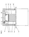
- FIG. 1 is a schematic diagram showing an overall configuration of a rotating electrical machine 100 according to an embodiment of the present invention.
- the inside of the rotating electrical machine 100 is shown by making a part of the rotating electrical machine 100 into a cross section.
- the rotating electrical machine 100 is disposed inside the case 10 as shown in FIG.
- the rotating electrical machine 100 includes a housing 112, a stator 130 having a stator core 132 fixed to the housing 112, and a rotor 150 that is rotatably disposed in the stator 130.
- the case 10 includes an engine case and a transmission case.
- Rotating electric machine 100 is a three-phase synchronous motor with a built-in permanent magnet.
- the rotating electrical machine 100 operates as an electric motor that rotates the rotor 150 when a three-phase alternating current is supplied to the stator coil 138 wound around the stator core 132.
- the rotating electrical machine 100 When the rotating electrical machine 100 is driven by an engine, the rotating electrical machine 100 operates as a generator and outputs three-phase AC generated power. That is, the rotating electrical machine 100 has both a function as an electric motor that generates rotational torque based on electric energy and a function as a generator that generates electric power based on mechanical energy. Functions can be used selectively.
- the stator 130 fixed to the housing 112 is fixedly held in the case 10 by fastening a flange 115 provided on the housing 112 to the case 10 with a bolt 12.
- the rotor 150 is fixed to the shaft 118 supported by the bearings 14A and 14B of the case 10, and is rotatably held inside the stator core 132.
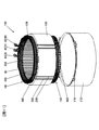
- FIG. 2 is a perspective view showing the housing 112 and the stator 130 of the rotating electrical machine 100 according to the first embodiment of the present invention.
- the housing 112 is formed into a cylindrical shape by drawing a steel plate (such as a high-tensile steel plate) having a thickness of about 2 to 5 mm.
- the housing 112 is provided with a plurality of flanges 115 attached to the case 10.
- the plurality of flanges 115 project outward in the radial direction at the periphery of one end surface of the cylindrical housing 112.
- the flange 115 is formed by cutting away portions other than the flange 115 at the end portion formed during drawing, and is integrated with the housing 112.
- the stator 130 has a cylindrical stator core 132 and a stator coil 138 attached to the stator core 132.
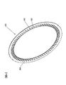
- FIG. 3 is a perspective view showing the stator core 132
- FIG. 4 is a perspective view showing the electromagnetic steel sheet 133 constituting the stator core 132.
- the stator core 132 is formed such that a plurality of slots 420 parallel to the axial direction of the stator core 132 are equally spaced in the circumferential direction.
- the number of slots 420 is, for example, 72 in the present embodiment, and the stator coils 138 described above are accommodated in the slots 420.
- the inner circumferential side of each slot 420 is an opening, and the circumferential width of this opening is substantially equal to or slightly smaller than the coil mounting portion of each slot 420 in which the stator coil 138 is mounted.
- Teeth 430 are formed between the slots 420, and each tooth 430 is integrated with an annular core back 440. That is, the stator core 132 is an integrated core in which the teeth 430 and the core back 440 are integrally formed.
- the teeth 430 serve to guide the rotating magnetic field generated by the stator coil 138 to the rotor 150 and generate a rotating torque in the rotor 150.
- the stator core 132 is formed by punching or etching a magnetic steel sheet 133 (see FIG. 4) having a thickness of about 0.05 to 1.0 mm, and laminating a plurality of formed annular magnetic steel sheets 133. It becomes.
- the stator core 132 is fitted and fixed to the inside of the cylindrical housing 112 by shrink fitting.
- the stator core 132 is arranged, and the housing 112 that has been heated in advance and expanded in inner diameter by thermal expansion is fitted into the stator core 132.
- the housing 112 is cooled to shrink the inner diameter, whereby the outer peripheral portion of the stator core 132 is tightened by the heat shrinkage.
- the inner diameter dimension of the housing 112 is set smaller than the outer diameter dimension of the stator core 132 by a predetermined value so that the stator core 132 does not idle with respect to the housing 112 due to a reaction caused by the torque of the rotor 150 during operation.
- the stator core 132 is firmly fixed in the housing 112 by shrink fitting.
- the difference between the outer diameter of the stator core 132 at normal temperature and the inner diameter of the housing 112 is referred to as a tightening allowance.
- the tightening allowance assuming the maximum torque of the rotating electrical machine 100, the housing 112 can have a predetermined tightening force.
- the stator core 132 is held.
- stator core 132 is not limited to being fitted and fixed by shrink fitting, but may be fixed to the housing 112 by press fitting.
- the stator core 132 in the present embodiment is provided with a welded portion 200 as a reinforcing portion as shown in FIG.
- the reinforcing portion connects the laminated electromagnetic steel plates 133 and suppresses deformation of the electromagnetic steel plates 133 due to the tightening force of the housing 112.
- the reinforcing part will be described later.
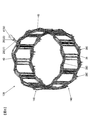
- FIG. 5 is a perspective view showing a stator coil 138 for three phases.
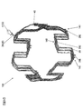
- FIGS. 6, 7 and 8 are perspective views showing a U-phase stator coil 138, a U1-phase stator coil 138 and a U2-phase stator coil 138 wound around the stator core 132, respectively.
- the stator coil 138 is wound in a distributed winding manner and connected in a star connection configuration.
- the distributed winding is a winding method in which the phase windings are wound around the stator core 132 so that the phase windings are housed in two slots 420 that are spaced apart from each other across the plurality of slots 420.
- distributed winding is adopted as the winding method, so that the formed magnetic flux distribution is closer to a sine wave than concentrated winding, and has a feature that reluctance torque is likely to be generated.
- this rotating electrical machine 100 has improved controllability using field-weakening control and reluctance torque, and can be used over a wide rotational speed range from a low rotational speed to a high rotational speed, and is suitable for an electric vehicle. Excellent motor characteristics can be obtained.
- the upper / lower coil may be shifted by one slot at a time, and short-pitch winding may be performed so that harmonic components can be suppressed.
- the stator coil 138 constitutes a three-phase star-connected phase coil, and the cross section may be round or rectangular. Since the cross-section of the stator coil 138 tends to improve efficiency by using the cross-section inside the slot 420 as effectively as possible and reducing the space in the slot, the quadrilateral cross-section of the stator coil 138 tends to increase. It is desirable in terms of efficiency improvement.
- the square shape of the cross section of the stator coil 138 may be a shape in which the circumferential direction of the stator core 132 is short and the radial direction is long, or conversely, the circumferential direction is long and the radial direction is short. It may be.
- the stator coil 138 has a rectangular wire in which the rectangular cross section of the stator coil 138 is long in the circumferential direction of the stator core 132 and short in the radial direction of the stator core 138 in each slot 420. It is used (see FIG. 9B).
- the rectangular wire has an outer periphery covered with an insulating film.
- the stator coil 138 is a segment type coil formed by connecting a plurality of U-shaped segment conductors 28 to each other.
- the segment conductor 28 has a central portion 28 ⁇ / b> C disposed at one coil end 140, and both end portions 28 ⁇ / b> E and 28 ⁇ / b> E are welded at the other coil end 140.
- the stator coil 138 includes six coils (U 1, U 2, V 1, V 2, W 1, W 2) as a whole (see FIG. 5) that are closely attached to the stator core 132. .
- the six coils constituting the stator coil 138 are arranged at appropriate intervals by the slot 420.
- one coil end 140 of the stator coil 138 has AC terminals 41 (U), 42 (V), which are coil conductors for input / output of the stator coils 138 of each of the UVW three phases. 43 (W) and the neutral point connection conductor 40 are drawn out.
- the AC terminals 41 (U), 42 (V), and 43 (W) for receiving the three-phase AC power are arranged in the axial direction of the stator core 132 from the coil end 140. It is arranged so as to protrude outward.
- the stator 130 is connected to a power converter (not shown) via AC terminals 41 (U), 42 (V), and 43 (W), so that AC power is supplied.
- Two neutral point connection conductors 40 arranged on both sides of the coil conductor for input / output are a U1 phase neutral wire that is the end of winding of the U1 phase, a V1 phase neutral wire that is the end of winding of the V1 phase, and W1. It consists of a W1 phase neutral wire that is the end of winding of the phase.
- Each neutral point connection conductor 40 has a structure in which three neutral wires are welded in advance, are epoxy-coated, and are directly wound around the top surface of the coil on the crown side.
- a jumper wire is arranged at the coil end 140, which is a portion of the stator coil 138 that protrudes outward in the axial direction from the stator core 132.
- This has the effect of reducing the overall size of the rotating electrical machine.
- the coil end 140 is orderly from the viewpoint of improving the reliability of the insulation characteristics. Since it is a direct oil cooling system in which cooling oil is directly applied to the coil end 140, when the coil end 140 is in order, the cooling oil is applied to the coil surface, so that the cooling performance is good.
- U, V, and W terminals are connected by resistance brazing using terminal parts for rectangular wires.
- the terminal parts are formed by punching a copper plate and extruding a plurality of projections with a diameter of 1 to 3 with punches from the back side of the copper plate so that the height is 0.1 mm to 0.2 mm. It is a projection system in which a copper plate and a brazing material are sandwiched between electrodes and energized while being pressurized.
- the contact portion between the copper plate and the brazing material generates heat locally, and the brazing material is melted and joined to the copper plate to be temporarily fixed. Since the brazing material is temporarily fixed by a plurality of projections, the brazing material is hardly affected by the tensile stress at the time of bending, and cracking and peeling of the brazing material can be prevented. In addition, you may use the clad material to which the brazing material has been attached beforehand. Alternatively, the terminal may be a terminal only with heat caulking. A temperature measuring sensor is enclosed by a tube such as a heat shrinkable tube and is brought into contact with a rectangular coil.
- the stator coil 138 has a structure in which the outer periphery of the conductor is covered with an insulating film, and the electrical insulation is maintained. In addition to the insulating film, the insulation voltage is maintained by the insulating paper 300 (see FIG. 2). This is preferable because the reliability can be further improved.
- the insulating paper 300 is disposed in the slot 420 and the coil end 140.
- the insulating paper 300 (so-called slot liner) disposed in the slot 420 is disposed between the segment conductors 28 inserted into the slot 420 and between the segment conductor 28 and the inner surface of the slot 420 (FIG. 9 ( b)), the dielectric strength between the segment conductors and between the segment conductor 28 and the inner surface of the slot 420 is improved.
- the slot liner shape is B-shaped for the purpose of reinforcing the insulation between the ground and the different phases as well as between the ground and different phases, and each coil is covered with a slot liner.
- the insulating paper 300 disposed at the coil end 140 is used by being annularly disposed between the segment conductors for interphase insulation and interconductor insulation at the coil end 140.
- the insulating paper 300 is an insulating sheet of heat-resistant polyamide paper, for example, and has a thickness of about 0.1 to 0.5 mm.
- the rectangular wire has a relatively wide coil interval, and high fluidity such as an insulating varnish flows down without adhering to the coil surface, so an insulator is used to positively adhere the varnish to the coil surface. Yes.
- the varnish can be permeated widely. Since cooling oil flows along the insulator, the coil end 140 can be effectively cooled.
- FIG. 9A is a schematic diagram showing cross sections of the rotor 150 and the stator 130.
- FIG. 9A the illustration of the stator coil 138 and the insulating paper 300 housed in the shaft 118 and the slot 420 is omitted to avoid complexity.
- FIG. 9B is an enlarged schematic diagram of a part A in FIG. 9A, and illustrates the stator coil 138 and the insulating paper 300 disposed in the slot 420.
- the rotor 150 includes a rotor core 152 and permanent magnets 154 held in magnet insertion holes formed in the rotor core 152.
- the rotor core 152 has a skew structure divided in the axial direction, and the magnet is divided in the axial direction. For example, the magnet is divided into two parts per pole and has a 12-pole V-shaped structure.
- the width of the magnet insertion hole in the circumferential direction is larger than the width of the permanent magnet 154 in the circumferential direction, and magnetic gaps 156 are formed on both sides of the permanent magnet 154.
- the magnetic gap 156 may be embedded with an adhesive, or may be solidified integrally with the permanent magnet 154 with a resin.
- -permanent magnet- Permanent magnet 154 forms a field pole of rotor 150.
- one magnetic pole is formed by one permanent magnet 154, but one magnetic pole may be formed by a plurality of permanent magnets. By increasing the number of permanent magnets for forming each magnetic pole, the magnetic flux density of each magnetic pole emitted from the permanent magnet is increased, and the magnet torque can be increased.
- the magnetization direction of the permanent magnet 154 is directed in the radial direction, and the direction of the magnetization direction is reversed for each field pole. That is, if the surface on the stator side of the permanent magnet 154 for forming a certain magnetic pole is magnetized to the N pole and the surface on the shaft side is magnetized to the S pole, the stator side of the permanent magnet 154 that forms the adjacent magnetic pole is assumed. The surface is magnetized so as to be the south pole and the shaft side surface is the north pole.
- the 12 permanent magnets 154 are magnetized so as to change the magnetization direction alternately for each magnetic pole at equal intervals in the circumferential direction, so that the rotor 150 forms 12 magnetic poles. ing.
- the permanent magnet 154 may be magnetized and then embedded in the magnet insertion hole of the rotor core 152, or the permanent magnet 154 may be inserted into the magnet insertion hole of the rotor core 152 before being magnetized, and then a strong magnetic field is applied to magnetize the permanent magnet 154. You may make it do.
- the magnetized permanent magnet 154 has a strong magnetic force. If the magnet is magnetized before the permanent magnet 154 is fixed to the rotor 150, a strong attractive force is generated between the permanent magnet 154 and the rotor core 152. This suction force prevents the work. There is a possibility that dust such as iron powder adheres to the permanent magnet 154 due to the strong attractive force. Therefore, in order to improve the productivity of the rotating electrical machine 100, it is desirable that the permanent magnet 154 is magnetized after being inserted into the magnet insertion hole of the rotor core 152.
- the permanent magnet 154 a neodymium-based or samarium-based sintered magnet, a ferrite magnet, a neodymium-based bonded magnet, or the like can be used.
- the residual magnetic flux density of the permanent magnet 154 is preferably about 0.4 to 1.3 T, and a neodymium magnet is more suitable.
- the auxiliary magnetic pole 160 is formed between the permanent magnets 154 forming the magnetic pole.
- the auxiliary magnetic pole 160 acts to reduce the magnetic resistance of the q-axis magnetic flux generated by the stator coil 138.
- the auxiliary magnetic pole 160 causes the reluctance torque to be generated because the magnetic resistance of the q-axis magnetic flux is much smaller than the magnetic resistance of the d-axis magnetic flux.
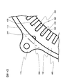
- FIG. 10 is a schematic plan view showing a state where the stator core 132 of the rotating electrical machine 100 according to the first embodiment of the present invention is fixed to the housing 112 by shrink fitting or press fitting.
- illustration of the stator coil 138 and the insulating paper 300 disposed inside the slot 420 is omitted.
- stator core 132 is fitted and fixed to the housing 112 by shrink fitting or press fitting.
- a compression stress is generated in the stator core 132 after the shrink-fitting or press-fitting due to the fastening force of the housing 112. This compressive stress is concentrated particularly on the portion of the housing 112 where the flange 115 abuts.
- the electromagnetic steel sheet 133 constituting the stator core 132 is deformed to have a shape corrugated in the axial direction.
- the insulating paper 300 disposed in the slot 420 and the insulating coating of the stator coil 138 are damaged, and the coil conductors and the coil conductors and the stator core 132 are separated. There is a risk of short-circuiting and reducing insulation.
- the stator core surface is deformed, the creeping distance between the stator core 132 and the coil conductor at the coil end 140 is shortened, and the coil conductor and the stator core 132 may be short-circuited.
- the tendency for the insulation properties to decrease becomes more prominent as the space factor of the electric conductor is improved due to downsizing and higher output of the rotating electrical machine 100.
- the tendency for the insulating properties to decrease becomes more prominent as the density of the coil ends 140 is increased.
- the tendency for the insulation to decrease becomes more prominent as the maximum tightening torque of the housing 112 increases.
- the welded portion is located at a position corresponding to the flange 115 of the housing 112 in the stator core 132, that is, a portion where stress is concentrated.
- Reference numeral 200 is provided as a reinforcing portion.
- the welded portion 200 is provided in parallel to the axial direction of the stator core 132 at the outer peripheral portion of the cylindrical stator core 132 by TIG welding or laser welding. As shown in FIG. 10, the welded portion 200 is formed in a semicircular weld groove 210 provided in advance on the outer peripheral portion of the stator core 132, and the welded portion 200 is radially outward of the stator core 132. It does not protrude.
- the weld groove 210 is disposed on the central axis X of the tooth 430 so as not to block the flow of magnetic flux in a portion where the magnetic flux density is high. That is, the welding groove 210 is provided on the central axis X of the part constituting the teeth 430 of each electromagnetic steel sheet 133. In addition, by providing the core back 440 with a sufficient width, it is possible to form the welding groove 210 other than on the central axis X of the teeth 430.
- the rigidity of the portion where stress is concentrated is improved, so that deformation of the electromagnetic steel sheet 133 (that is, deformation of the core back 440 and the teeth 430) can be suppressed.
- the insulating paper 300 and the insulating coating of the coil conductor from being damaged due to deformation of the core back 440 and the teeth 430.
- the creeping distance between the coil conductor and the stator core surface from being shortened due to deformation of the core back 440 and the teeth 430.
- the rotating electrical machine 100 having the stator 130 with excellent insulation characteristics can be provided.
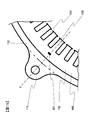
- FIG. 11 is a perspective view showing the stator 130 and the housing 112 of the rotating electrical machine 100 according to the second embodiment of the present invention
- FIG. 12 shows the fixing of the rotating electrical machine 100 according to the second embodiment of the present invention
- FIG. 6 is a schematic plan view showing a state in which the core iron core 132 is fixed to the housing 112 by shrink fitting or press fitting.
- the same or corresponding parts as those in the first embodiment are denoted by the same reference numerals and description thereof is omitted.
- FIG. 12 the illustration of the stator coil 138 and the insulating paper 300 disposed inside the slot 420 is omitted.
- a plurality of welding portions 200 as reinforcing portions are provided at positions corresponding to the flanges 115 on the outer peripheral portion of the stator core 132. According to the second embodiment, the same effects as (1) to (4) described in the first embodiment can be obtained. According to the second embodiment, the rigidity can be further improved by providing a plurality of welded portions 200, so that it is possible to cope with a case where a shrinkage allowance for press fitting or press fitting is large.
- the welded portions 200 may be provided at a total of three locations near the center of the flange 115 and near both ends of the flange 115 so as to correspond to the flange 115, or near both ends of the flange 115. You may install in two places.
- the welded portion 200 can be appropriately provided in the vicinity of the portion where the flange 115 abuts on the outer peripheral portion of the stator core 132.
- FIG. 13 is a schematic plan view showing a state where the stator core 132 of the rotating electrical machine 100 according to the third embodiment of the present invention is fixed to the housing 112 by shrink fitting or press fitting.
- the same or corresponding parts as those in the first embodiment are denoted by the same reference numerals and description thereof is omitted.
- illustration of the stator coil 138 and the insulating paper 300 is omitted.
- the welded portion 200 is provided on the bottom surface of the slot 420 at a position corresponding to the flange 115. That is, the welded portion 200 as a reinforcing portion is provided at a position corresponding to the flange 115 in the inner peripheral portion of the stator core 132.
- the same effects as (1) to (4) described in the first embodiment can be obtained.
- the rigidity can be further improved. It is also possible to cope with a case where the margin for tightening is large.
- FIG. 14 is a schematic plan view showing a state where the stator core 132 of the rotating electrical machine 100 according to the fourth embodiment of the present invention is fixed to the housing 112 by shrink fitting or press fitting.
- the same or corresponding parts as those in the first embodiment are denoted by the same reference numerals and description thereof is omitted.
- illustration of the stator coil 138 and the insulating paper 300 is omitted.
- the welded portion 200 is provided on the outer peripheral portion of the stator core 132 and the bottom surface of the slot 420. That is, the welded portion 200 as the reinforcing portion is provided at a position corresponding to the flange 115 in the outer peripheral portion and the inner peripheral portion of the stator core 132. According to the fourth embodiment, the rigidity of the stator core 132 is further improved by providing the welded portions 200 not only on one of the outer peripheral portion and the inner peripheral portion, but also on the first portion described above. The same effects as those of the third embodiment can be obtained.
- FIG. 15 is a schematic plan view showing a state where the stator core 132 of the rotating electrical machine 100 according to the fifth embodiment of the present invention is fixed to the housing 112 by shrink fitting or press fitting
- FIG. It is a schematic diagram which shows the cross section.
- the same or corresponding parts as those in the first embodiment are denoted by the same reference numerals and description thereof is omitted.
- illustration of the stator coil 138 and the insulating paper 300 is omitted.
- the caulking portion 201 for laminating and fixing the electromagnetic steel plates 133 constituting the stator core 132 is formed as a reinforcing portion that increases the rigidity of the portion corresponding to the flange 115. Since the caulking portion 201 is provided on the central axis X of the tooth 430, a sufficient flow of magnetic flux can be ensured.
- the caulking part 201 has a trapezoidal convex part and a concave part formed in the laminating direction of the electromagnetic steel sheet 133 using a punch or the like.
- the caulking portion 201 is not limited to the case where V caulking is adopted, and round caulking may be adopted.
- the caulking portion 201 since the caulking portion 201 has a function as a reinforcing portion, the cases (1) to (4) described in the first embodiment when the tightening allowance is relatively small. ) Has the same effect.
- FIG. 17 is a perspective view showing a stator core 132 of the rotating electrical machine 100 according to the sixth embodiment of the present invention.
- the stator core 132 can be manufactured by so-called rolling, so that the shape accuracy can be improved.
- Spinning is a method for manufacturing a stator core 132 in which a plurality of laminates 134 each made up of a predetermined number of electromagnetic steel sheets 133 are sequentially shifted by a predetermined angle in the circumferential direction, thereby leveling the thickness deviation. .
- the six cores 134 are rotated by 60 degrees to form the stator core 132.
- the stator core 132 When the stator core 132 is formed by rolling and stacking, it is necessary to previously form the welding grooves 210 at a predetermined interval, and to match the welding grooves 210 of the stacked body 134 that are arranged with a predetermined angle shift.
- the welding groove 210 is provided every 30 degrees.
- the position where the welding groove 210 is formed may be determined in advance in consideration of turning and stacking.
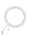
- the position and shape of the flange 115 depend on the shape of the engine case or transmission case to which the rotating electrical machine 100 is attached. Because of the difference, as shown in FIG. 18, it is preferable to provide weld grooves 210 in the outer peripheral portion on the central axis of all the teeth 430 of the stator core 132 in advance. Thereby, whatever position the flange 115 is, it is preferable because the welding groove 210 of each laminated body 134 can be made to coincide at a position corresponding to the flange 115 at the time of rolling. Since the welding groove 210 is formed on the central axis of the teeth 430, the flow of magnetic flux is not hindered in a portion where the magnetic flux density is high.
- the weld core 200 is not formed in all the weld grooves 210 but the stator core 132 is sintered.
- the housing 112 is fitted or fixed by fitting or press-fitting, the welded portion 200 is provided in the welding groove 210 disposed corresponding to the flange 115 of the housing 112. According to the sixth embodiment, the same effects as (1) to (4) described in the first embodiment can be obtained.
- the reinforcing part is not limited to the case where either one of the welded part 200 or the caulking part 201 is adopted, and the welding part 200 and the caulking part 201 may be combined to form a reinforcing part.
- the caulking portion 201 may be formed as a reinforcing portion in a portion where the small flange 115 is located
- the welded portion 200 may be formed as a reinforcing portion in a portion where the large flange 115 is located. You may form both the welding part 200 and the crimping part 201 in the part in which the big flange 115 is located.
- the welded portion 200 for laminating and fixing the stator core 132 and the caulking portion 201 have a function as a reinforcing portion
- the welded portion 200 for connecting the electromagnetic steel sheet 133 It is good also as providing a reinforcement part separately from the crimping part 201.
- the welded part 200 may be provided not only for connecting the electromagnetic steel sheets 133 but to serve as a reinforcing part. That is, the reinforcing portion can be provided only in the vicinity of the flange 115 provided at one end of the housing 112. In other words, the reinforcing portion can be provided only around one end side of the stator core 132.
- a member such as a bar is attached to the outer peripheral portion of the stator core 132 instead of the welded portion 200 and the caulking portion 201.
- the reinforcing portion may be provided by being fitted in a groove provided and parallel to the axial direction of the stator core 132 and fixed by welding or the like.
- stator core 132 has been described only with respect to the integral core in which the plurality of teeth 430 are integrated with the core back 440, the stator core 132 to which the present invention is applicable is not limited to this.
- the present invention can also be applied to a case where a stator core 132 made of a plurality of divided cores is fitted and fixed to the housing 112 by shrink fitting or press fitting.
- the present invention is not limited to the case where it is applied to the stator core 132 to which the segment type coil is attached. Thereby, the stress applied to the stator coil 138 due to the deformation of the stator core 132 can be suppressed, and damage to the insulating film of the coil conductor can be prevented.
Landscapes
- Engineering & Computer Science (AREA)
- Power Engineering (AREA)
- Iron Core Of Rotating Electric Machines (AREA)
- Motor Or Generator Frames (AREA)
Abstract
回転電機は、ケースに取り付けられる複数のフランジを有する円筒状のハウジングと、ハウジングに焼嵌めまたは圧入により固定される円筒状の固定子鉄心を有する固定子と、固定子内に回転自在に配設される回転子と、を備え、固定子鉄心は、複数枚の鋼板が積層されてなり、鋼板の変形を抑制するための溶接部が、固定子鉄心におけるハウジングのフランジに対応する位置に設けられている。
Description
本発明は、回転電機に関し、特に自動車の走行のためにトルクを発生したり、あるいは制動時に発電したりする回転電機に関する。
回転電機は、固定子と回転子とを備えており、固定子は多数のスロットが形成された固定子鉄心を有している。固定子鉄心は、鉄損を抑えるために、通常、0.05~1.0mm程度の電磁鋼板が所定枚数積層され、電磁鋼板の外周部の所定位置が溶接されるなどして一体化されている(特許文献1参照)。
このように作製された固定子鉄心には、コイルが巻装されている。回転電機は、コイルに交流電力が供給されることで回転磁界を発生させ、回転磁界により回転子を回転させる。回転電機は、回転子に加わる機械エネルギーを電気エネルギーに変換してコイルから交流電力を出力する。回転電機は、電動機または発電機として作動する。
固定子と、固定子の内側に回転可能に設けられた回転子と、固定子を焼嵌めや圧入で保持するハウジングと、を備えた回転電機が知られている。回転電機を自動車に搭載する場合、ハウジングの一端面に設けたフランジにより回転電機を自動車の適所に固定することがある。回転電機では、固定子鉄心におけるハウジングのフランジに対応する部分に圧縮応力が集中し、応力が集中する部分の電磁鋼板が波打つ(軸方向に張り出す)ように変形してしまうといった問題があった。
特に、自動車の走行に使用するトルクを発生するような回転電機では、ハウジングと固定子鉄心の締め代を大きく設定してハウジングの最大締め付けトルクを大きくする必要があるため、電磁鋼板の変形が生じやすい。
(1)本発明の第1の態様による回転電機は、ケースに取り付けられる複数のフランジを有する円筒状のハウジングと、ハウジングに焼嵌めまたは圧入により固定される円筒状の固定子鉄心を有する固定子と、固定子内に回転自在に配設される回転子と、を備え、固定子鉄心は、複数枚の鋼板が積層されてなり、鋼板の変形を抑制するための補強部が、固定子鉄心におけるハウジングのフランジに対応する位置に設けられている。
(2)本発明の第2の態様によると、第1の態様の回転電機において、補強部は、固定子鉄心の軸方向に平行に設けられた溶接部とされているのが好ましい。
(3)本発明の第3の態様によると、第1の態様の回転電機において、補強部は、鋼板同士を積層固定するための加締め部とされているのが好ましい。
(4)本発明の第4の態様によると、第2の態様の回転電機において、溶接部は、固定子鉄心の外周部および/または内周部に設けられているのが好ましい。
(5)本発明の第5の態様によると、第1ないし3のいずれか1の態様の回転電機において、補強部は、固定子鉄心のティースの中心軸上に配置されているのが好ましい。
(6)本発明の第6の態様によると、第2または4の態様の回転電機において、固定子鉄心の全てのティースの中心軸上における外周部に溶接溝が設けられており、ハウジングのフランジに対応して配置される溶接溝に溶接部が設けられているのが好ましい。
(7)本発明の第7の態様によると、第1ないし6のいずれか1の態様の回転電機において、固定子鉄心は、一体型コアであって、固定子鉄心には、固定子鉄心の軸方向に平行な複数のスロットが形成され、スロットには、複数のセグメント導体が互いに接続されてなるセグメント型コイルと、セグメント導体の相互間およびスロットとセグメント導体との間を絶縁するための絶縁紙と、が配設されているのが好ましい。
(8)本発明の第8の態様によると、第1ないし7のいずれか1の態様の回転電機において、複数のフランジは、円筒状のハウジングの一端面周縁において、径方向外方に突設されているのが好ましい。
本発明によれば、ハウジングに焼嵌めまたは圧入により固定された固定子鉄心に加わる締め付け力を起因とする固定子鉄心の変形を抑制できる回転電機を提供することができる。
以下、本発明の実施形態を図に基づいて詳説する。
[第1の実施形態]
―回転電機の全体構成―
本実施形態に係る回転電機は、自動車の走行に使用するのが好適な回転電機である。回転電機を使用するいわゆる電気自動車には、エンジンと回転電機の両方を備えるハイブリッドタイプの電気自動車(HEV)と、エンジンを用いないで回転電機のみで走行する純粋な電気自動車(EV)とがあるが、以下に説明する回転電機は両方のタイプに利用できるので、代表してハイブリッドタイプの電気自動車に用いられる回転電機に基づいて説明する。
[第1の実施形態]
―回転電機の全体構成―
本実施形態に係る回転電機は、自動車の走行に使用するのが好適な回転電機である。回転電機を使用するいわゆる電気自動車には、エンジンと回転電機の両方を備えるハイブリッドタイプの電気自動車(HEV)と、エンジンを用いないで回転電機のみで走行する純粋な電気自動車(EV)とがあるが、以下に説明する回転電機は両方のタイプに利用できるので、代表してハイブリッドタイプの電気自動車に用いられる回転電機に基づいて説明する。
図1は、本発明の実施形態に係る回転電機100の全体構成を示す模式図である。図1では、回転電機100の一部分を断面とすることで、回転電機100の内部を示している。
回転電機100は、図1に示すように、ケース10の内部に配設される。回転電機100は、ハウジング112と、ハウジング112に固定される固定子鉄心132を有する固定子130と、固定子130内に回転自在に配設される回転子150と、を備えている。ケース10は、エンジンのケースや変速機のケースによって構成される。
回転電機100は、永久磁石内蔵型の三相同期モータである。回転電機100は、固定子鉄心132に巻回される固定子コイル138に三相交流電流が供給されることで、回転子150を回転させる電動機として作動する。回転電機100は、エンジンによって駆動されると、発電機として作動して三相交流の発電電力を出力する。つまり、回転電機100は、電気エネルギーに基づいて回転トルクを発生する電動機としての機能と、機械エネルギーに基づいて発電を行う発電機としての機能の両方を有しており、自動車の走行状態によって上記機能を選択的に利用することができる。
ハウジング112に固定された固定子130は、ハウジング112に設けられたフランジ115がボルト12によりケース10に締結されることで、ケース10内に固定保持されている。
回転子150は、ケース10の軸受け14A、14Bにより支承されるシャフト118に固定されており、固定子鉄心132の内側において回転可能に保持されている。
図2を参照してハウジング112および固定子130について説明する。図2は、本発明の第1の実施形態に係る回転電機100のハウジング112と固定子130とを示す斜視図である。
―ハウジング―
ハウジング112は、厚さ2~5mm程度の鋼板(高張力鋼板など)を絞り加工により円筒形状に形成されている。ハウジング112には、ケース10に取り付けられる複数のフランジ115が設けられている。複数のフランジ115は、円筒状のハウジング112の一端面周縁において、径方向外方に突設されている。フランジ115は、絞り加工時に形成される端部において、フランジ115以外の部分を切除して形成されるものであり、ハウジング112と一体となっている。
ハウジング112は、厚さ2~5mm程度の鋼板(高張力鋼板など)を絞り加工により円筒形状に形成されている。ハウジング112には、ケース10に取り付けられる複数のフランジ115が設けられている。複数のフランジ115は、円筒状のハウジング112の一端面周縁において、径方向外方に突設されている。フランジ115は、絞り加工時に形成される端部において、フランジ115以外の部分を切除して形成されるものであり、ハウジング112と一体となっている。
―固定子―
固定子130は、円筒状の固定子鉄心132と、この固定子鉄心132に装着される固定子コイル138と、を有している。
固定子130は、円筒状の固定子鉄心132と、この固定子鉄心132に装着される固定子コイル138と、を有している。
―固定子鉄心―
固定子鉄心132について、図3および図4を参照して説明する。図3は、固定子鉄心132を示す斜視図であり、図4は、固定子鉄心132を構成する電磁鋼板133を示す斜視図である。固定子鉄心132は、図3に示すように、固定子鉄心132の軸方向に平行な複数のスロット420が周方向に等間隔となるように形成されている。
固定子鉄心132について、図3および図4を参照して説明する。図3は、固定子鉄心132を示す斜視図であり、図4は、固定子鉄心132を構成する電磁鋼板133を示す斜視図である。固定子鉄心132は、図3に示すように、固定子鉄心132の軸方向に平行な複数のスロット420が周方向に等間隔となるように形成されている。
スロット420の数は、例えば本実施の形態では72個であり、スロット420に上記した固定子コイル138が収容される。各スロット420の内周側は開口とされ、この開口の周方向の幅は、固定子コイル138が装着される各スロット420のコイル装着部とほぼ同等もしくは、コイル装着部よりも若干小さい。
スロット420間にはティース430が形成されており、それぞれのティース430は環状のコアバック440と一体となっている。つまり、固定子鉄心132は、各ティース430とコアバック440とが一体成形された一体型コアとされている。
ティース430は、固定子コイル138によって発生した回転磁界を回転子150に導き、回転子150に回転トルクを発生させる働きをする。
固定子鉄心132は、厚さ0.05~1.0mm程度の電磁鋼板133(図4参照)を打ち抜き加工またはエッチング加工により成形し、成形された円環形状の電磁鋼板133を複数枚積層してなる。
固定子鉄心132は、上記した円筒状のハウジング112の内側に焼嵌めにより嵌合固定される。具体的な組み立て方としては、例えば、先ず固定子鉄心132を配置しておき、予め加熱して熱膨張により内径を広げておいたハウジング112を固定子鉄心132に嵌め込む。次に、ハウジング112を冷却して内径を収縮させることで、その熱収縮により固定子鉄心132の外周部を締め付ける。
運転時における回転子150のトルクによる反作用によって固定子鉄心132がハウジング112に対して空転しないように、ハウジング112の内径寸法は固定子鉄心132の外径寸法よりも所定値だけ小さく設定されており、焼嵌め嵌合により固定子鉄心132がハウジング112内に強固に固定されるようになっている。
常温における固定子鉄心132の外径と、ハウジング112の内径との差を締め代といい、締め代を回転電機100の最大トルクを想定して設定することで、ハウジング112は所定の締め付け力により固定子鉄心132を保持することになる。
なお、固定子鉄心132は焼嵌めにより嵌合固定する場合に限定されることなく、圧入によりハウジング112に嵌合固定することとしてもよい。
本実施形態における固定子鉄心132には、図3に示すように、補強部としての溶接部200が設けられている。補強部は、積層された各電磁鋼板133を接続するとともに、ハウジング112の締め付け力に起因する電磁鋼板133の変形を抑制する。補強部については、後述する。
―固定子コイル―
図2および図5~8を参照して固定子コイル138について説明する。図5は、三相分の固定子コイル138を示す斜視図である。図6、7および8は、それぞれ固定子鉄心132に巻回されるU相の固定子コイル138、U1相の固定子コイル138およびU2相の固定子コイル138を示す斜視図である。
図2および図5~8を参照して固定子コイル138について説明する。図5は、三相分の固定子コイル138を示す斜視図である。図6、7および8は、それぞれ固定子鉄心132に巻回されるU相の固定子コイル138、U1相の固定子コイル138およびU2相の固定子コイル138を示す斜視図である。
固定子コイル138は分布巻の方式で巻かれ、スター結線の構成で接続されている。分布巻とは、複数のスロット420を跨いで離間した二つのスロット420に相巻線が収納されるように、相巻線が固定子鉄心132に巻かれる巻線方式である。本実施形態では、巻線方式として分布巻を採用しているので、形成される磁束分布は集中巻きに比べて正弦波に近く、リラクタンストルクを発生しやすい特徴を有している。そのため、この回転電機100は、弱め界磁制御やリラクタンストルクを活用する制御の制御性が向上し、低回転速度から高回転速度までの広い回転速度範囲に亘って利用が可能であり、電気自動車に適した優れたモータ特性を得ることができる。なお、上層/下層コイルで1スロットずつずらし高調波成分を抑制できるように短節巻をしてもよい。
固定子コイル138は三相のスター接続された相コイルを構成しており、断面が丸形状であっても、四角形状であってもよい。スロット420の内部の断面をできるだけ有効に利用し、スロット内の空間が少なくなるような構造とすることが効率の向上につながる傾向にあるため、固定子コイル138の断面は、四角形状の方が効率向上の点で望ましい。なお、固定子コイル138の断面の四角形状は、固定子鉄心132の周方向が短く、径方向が長い形状をしていてもよいし、逆に周方向が長く、径方向に短い形状をしていてもよい。
本実施形態では、固定子コイル138は、各スロット420内で固定子コイル138の長方形断面が固定子鉄心132の周方向について長く、固定子鉄心138の径方向について短い形状とされる平角線が使用されている(図9(b)参照)。この平角線は、外周が絶縁被膜で覆われている。
固定子コイル138は、図7および図8に示すように、U字形状の複数のセグメント導体28が互いに接続されることで形成されるセグメント型コイルとされる。セグメント導体28は、中央部28Cが一方のコイルエンド140に配置され、両端部28E、28Eが他方のコイルエンド140において溶接されている。
固定子コイル138は、図2に示すように、全体で6系統(U1、U2、V1、V2、W1、W2)のコイル(図5参照)が固定子鉄心132に密着して装着されている。固定子コイル138を構成する6系統のコイルは、スロット420によって相互に適正な間隔をもって配列される。
図5に示すように、固定子コイル138における一方のコイルエンド140には、UVW三相それぞれの固定子コイル138の入出力用のコイル導体である交流端子41(U)、42(V)、43(W)と、中性点結線用導体40と、が引き出されている。回転電機100の組み立てにおける作業性向上のために、三相交流電力を受けるための交流端子41(U)、42(V)、43(W)は、コイルエンド140から固定子鉄心132の軸方向外方に突出するように配置されている。固定子130は、交流端子41(U)、42(V)、43(W)を介して図示しない電力変換装置に接続されることで、交流電力が供給されるようになっている。入出力用のコイル導体の両側に配置した2箇所の中性点結線用導体40は、U1相の巻き終わりとなるU1相中性線とV1相の巻き終わりとなるV1相中性線とW1相の巻き終わりとなるW1相中性線で構成される。U2、V2、W2も同様である。それぞれの中性点結線用導体40は、中性線3本をあらかじめ溶接し、それらをエポキシコーティングしクラウン側のコイル上面に直接這い回す構造にしている。
図2および図5に示すように、固定子コイル138における固定子鉄心132から軸方向外方に飛び出した部分であるコイルエンド140には、渡り線が配置されており、全体として整然とした配置となっており、回転電機全体の小型化につながる効果がある。コイルエンド140が整然としていることは、絶縁特性に対する信頼性向上の観点からも望ましい。コイルエンド140に冷却油を直接かける直接油冷方式であるので、コイルエンド140が整然としているとコイル表面に冷却油が塗布されるため冷却性がよい。
たとえばU、V、Wの端末は、平角線用のターミナル部品によって抵抗ロウ付けで接続する。ターミナル部品は、銅板を打抜き加工し、φ1~3のプロジェクションを高さ0.1mm~0.2mmになるように銅板の裏側からパンチで複数個所押し出し成形する。銅板とろう材を電極で挟み込み、加圧しながら通電するプロジェクション方式になっている。
プロジェクションに電流が集中して流れるため、銅板とろう材の接触部が局部発熱し、ろう材が溶融し銅板と接合され仮固定できる構造にした。複数箇所のプロジェクションでろう材を仮固定しているので、曲げ成形時の引張応力の影響を受けにくく、ろう材の割れや剥がれを防止することができる。なお、あらかじめろう材がついているクラッド材を用いてもよい。もしくは、端子は熱加締めのみの端子でもよい。温度測定用のセンサーを熱収縮チューブなどのチューブによって囲い平角コイルに接触させている。
固定子コイル138は、導体の外周が絶縁被膜で覆われた構造とされ、電気的な絶縁性が維持されているが、絶縁被膜に加えて絶縁紙300(図2参照)により絶縁耐圧を維持することで、より信頼性の向上を図ることができるため好適である。
絶縁紙300は、スロット420やコイルエンド140に配設される。スロット420に配設される絶縁紙300(いわゆるスロットライナー)は、スロット420に挿通されるセグメント導体28の相互間およびセグメント導体28とスロット420の内面との間に配設されて(図9(b)参照)、セグメント導体相互間やセグメント導体28とスロット420の内面との間の絶縁耐圧を向上する。
たとえば、高電圧ではスロットライナー形状は、対地間・異相間の他に同相間も絶縁強化を図る目的でB字形状にし、コイル1本毎にスロットライナーで覆う構造になっている。
図2に示すように、コイルエンド140において配設される絶縁紙300は、コイルエンド140における相間絶縁、導体間絶縁のためにセグメント導体間に環状に配設して使用される。このように、本実施形態に係る回転電機100は、スロット420の内側やコイルエンド140において絶縁紙300が配設されているため、絶縁被膜が傷ついたり劣化したりしても、必要な絶縁耐圧を保持できる。絶縁紙300は、例えば耐熱ポリアミド紙の絶縁シートであり、厚さは0.1~0.5mm程である。
平角線は比較的コイル間隔が広く、絶縁ワニスのような流動性が高いものはコイル表面に付着せずに流れ落ちてしまうので、積極的にコイル表面にワニスを付着させるために、インシュレータを用いている。インシュレータにより、エポキシワニスを保持し、かつ表面に沿ってワニスを案内して流動させることによって、ワニスを広く浸透させることができる。インシュレータに沿って冷却油が流れるのでコイルエンド140を効果的に冷却できる構造になっている。
―回転子―
次に回転子150について、図1および図9を参照して説明する。図9(a)は、回転子150および固定子130の断面を示す模式図である。図9(a)では煩雑さを避けるために、シャフト118やスロット420の内部に収容されている固定子コイル138、絶縁紙300の図示は省略している。図9(b)は、図9(a)のA部拡大模式図であり、スロット420内に配設される固定子コイル138および絶縁紙300を図示している。
次に回転子150について、図1および図9を参照して説明する。図9(a)は、回転子150および固定子130の断面を示す模式図である。図9(a)では煩雑さを避けるために、シャフト118やスロット420の内部に収容されている固定子コイル138、絶縁紙300の図示は省略している。図9(b)は、図9(a)のA部拡大模式図であり、スロット420内に配設される固定子コイル138および絶縁紙300を図示している。
図1および図9(a)に示すように、回転子150は、回転子鉄心152と、回転子鉄心152に形成された磁石挿入孔に保持されている永久磁石154と、を有している。回転子鉄心152は軸方向に分割されたスキュー構造とされ、磁石は軸方向に分割されている。たとえば、磁石は1極あたり2分割されており、12極のV字状の構造になっている。
―回転子鉄心―
回転子鉄心152には、直方体形状の磁石挿入孔が外周部近傍において周方向に等間隔で形成されており、各磁石挿入孔には永久磁石154が埋め込まれ、接着剤などで固定されている。磁石挿入孔の円周方向の幅は、永久磁石154の円周方向の幅よりも大きく形成されており、永久磁石154の両側には磁気的空隙156が形成されている。磁気的空隙156は接着剤を埋め込んでもよいし、樹脂で永久磁石154と一体に固めてもよい。
回転子鉄心152には、直方体形状の磁石挿入孔が外周部近傍において周方向に等間隔で形成されており、各磁石挿入孔には永久磁石154が埋め込まれ、接着剤などで固定されている。磁石挿入孔の円周方向の幅は、永久磁石154の円周方向の幅よりも大きく形成されており、永久磁石154の両側には磁気的空隙156が形成されている。磁気的空隙156は接着剤を埋め込んでもよいし、樹脂で永久磁石154と一体に固めてもよい。
―永久磁石―
永久磁石154は、回転子150の界磁極を形成する。本実施形態では、一つの永久磁石154で一つの磁極を形成する構成としているが、一つの磁極を複数の永久磁石によって構成してもよい。各磁極を形成するための永久磁石を複数に増やすことで、永久磁石が発する各磁極の磁束密度が大きなり、磁石トルクを増大することができる。
永久磁石154は、回転子150の界磁極を形成する。本実施形態では、一つの永久磁石154で一つの磁極を形成する構成としているが、一つの磁極を複数の永久磁石によって構成してもよい。各磁極を形成するための永久磁石を複数に増やすことで、永久磁石が発する各磁極の磁束密度が大きなり、磁石トルクを増大することができる。
永久磁石154の磁化方向は径方向を向いており、界磁極毎に磁化方向の向きが反転している。すなわち、ある磁極を形成するための永久磁石154の固定子側の面がN極、シャフト側の面がS極に磁化されていたとすると、隣の磁極を形成する永久磁石154の固定子側の面はS極、シャフト側の面はN極となるように磁化されている。本実施形態では、12個の永久磁石154が、円周方向に等間隔で磁極毎に交互に磁化方向が変わるように磁化されて配置されることで、回転子150は12の磁極を形成している。
永久磁石154を磁化した後に回転子鉄心152の磁石挿入孔に埋め込んでもよいし、永久磁石154を磁化する前に回転子鉄心152の磁石挿入孔に挿入し、その後に強力な磁界を与えて磁化するようにしてもよい。
磁化後の永久磁石154は磁力が強力であり、回転子150に永久磁石154を固定する前に磁石を着磁すると、永久磁石154の固定時に回転子鉄心152との間に強力な吸引力が生じ、この吸引力が作業の妨げとなる。強力な吸引力により、永久磁石154に鉄粉などのごみが付着するおそれもある。そのため、永久磁石154を回転子鉄心152の磁石挿入孔に挿入した後に磁化する方が、回転電機100の生産性を向上させる上で望ましい。永久磁石154には、ネオジウム系、サマリウム系の焼結磁石やフェライト磁石、ネオジウム系のボンド磁石などを用いることができる。永久磁石154の残留磁束密度は、0.4~1.3T程度が望ましく、ネオジウム系の磁石がより適している。
本実施形態では、磁極を形成する各永久磁石154間に補助磁極160が形成されている。補助磁極160は、固定子コイル138が発生するq軸の磁束の磁気抵抗が小さくなるように作用する。補助磁極160により、q軸の磁束の磁気抵抗がd軸の磁束の磁気抵抗に比べて非常に小さくなるため、大きなリラクタンストルクが発生することになる。
三相交流電流が固定子コイル138に供給されることにより固定子130に回転磁界が発生すると、回転磁界が回転子150の永久磁石154に作用して磁石トルクが発生する。回転子150には、磁石トルクに加えて、上述のリラクタンストルクが発生するので、回転子150には上述の磁石トルクとリラクタンストルクとの両方のトルクが回転トルクとして作用し、大きな回転トルクを得ることができる。
―補強部―
補強部について、図2、図3および図10を参照して説明する。図10は、本発明の第1の実施形態に係る回転電機100の固定子鉄心132をハウジング112に焼嵌めまたは圧入により固定した状態を示す平面模式図である。図10において、スロット420の内部に配置されている固定子コイル138や絶縁紙300の図示は省略している。
補強部について、図2、図3および図10を参照して説明する。図10は、本発明の第1の実施形態に係る回転電機100の固定子鉄心132をハウジング112に焼嵌めまたは圧入により固定した状態を示す平面模式図である。図10において、スロット420の内部に配置されている固定子コイル138や絶縁紙300の図示は省略している。
上述したように、固定子鉄心132は、ハウジング112に焼嵌めまたは圧入により嵌合固定される。焼嵌めまたは圧入後の固定子鉄心132には、ハウジング112の締め付け力により圧縮応力が生じる。この圧縮応力は、特にハウジング112のフランジ115が当接する部分に集中する。その結果、固定子鉄心132を構成する電磁鋼板133が変形して軸方向に波打ちした形状になる。
電磁鋼板133が軸方向に張り出すように変形すると、スロット420に配設される絶縁紙300や固定子コイル138の絶縁被膜が損傷して、コイル導体同士やコイル導体と固定子鉄心132とが短絡して絶縁性が低下しまうおそれがある。固定子鉄心面が変形することによって、コイルエンド140における固定子鉄心132とコイル導体との沿面距離が短くなり、コイル導体と固定子鉄心132とが短絡してしまうおそれもある。絶縁性が低下する傾向は、回転電機100の小型化、高出力化による電気導体の占積率を向上させるほど顕著となる。絶縁性が低下する傾向は、コイルエンド140の高密度化を高めるほど顕著となる。絶縁性が低下する傾向は、ハウジング112の最大締め付けトルクが大きくなるにつれ顕著となる。
したがって、本実施形態では、電磁鋼板133の変形を抑制して十分な絶縁性を確保するために、固定子鉄心132におけるハウジング112のフランジ115に対応する位置、すなわち応力が集中する部分に溶接部200が補強部として設けられている。
溶接部200は、TIG溶接やレーザー溶接などにより、円筒状の固定子鉄心132の外周部において、固定子鉄心132の軸方向に平行に設けられている。溶接部200は、図10に示すように、固定子鉄心132の外周部に予め設けられた半円状の溶接溝210に形成されており、溶接部200が固定子鉄心132の径方向外方に突出することはない。
溶接溝210は、磁束密度の高い部分において磁束の流れを遮ることのないように、ティース430の中心軸X上に配置されている。すなわち、各電磁鋼板133のティース430を構成する部分の中心軸X上に溶接溝210が設けられている。なお、コアバック440に十分な幅を持たせることで、ティース430の中心軸X上以外に溶接溝210を形成することができる。
以上説明した第1の実施の形態によれば、以下のような作用効果を奏することができる。
(1)溶接部200を補強部として形成することにより、応力が集中する部分の剛性が向上するため、電磁鋼板133の変形(すなわちコアバック440やティース430の変形)を抑えることができる。
(2)(1)により、コアバック440やティース430の変形を起因として絶縁紙300やコイル導体の絶縁被膜が損傷することを防止できる。
(3)(1)により、コアバック440やティース430の変形を起因としてコイル導体と固定子鉄心面との沿面距離が短くなることを防止できる。
(4)(1)~(3)により、絶縁特性の優れた固定子130を有する回転電機100を提供することができる。
(1)溶接部200を補強部として形成することにより、応力が集中する部分の剛性が向上するため、電磁鋼板133の変形(すなわちコアバック440やティース430の変形)を抑えることができる。
(2)(1)により、コアバック440やティース430の変形を起因として絶縁紙300やコイル導体の絶縁被膜が損傷することを防止できる。
(3)(1)により、コアバック440やティース430の変形を起因としてコイル導体と固定子鉄心面との沿面距離が短くなることを防止できる。
(4)(1)~(3)により、絶縁特性の優れた固定子130を有する回転電機100を提供することができる。
[第2の実施形態]
図11および図12を参照して、本発明による回転電機100の第2の実施形態について説明する。図11は、本発明の第2の実施形態に係る回転電機100の固定子130およびハウジング112を示す斜視図であり、図12は、本発明の第2の実施形態に係る回転電機100の固定子鉄心132をハウジング112に焼嵌めまたは圧入により固定した状態を示す平面模式図である。図中第1の実施形態と同一もしくは相当部分には同一符号を付し説明を省略する。図12において、スロット420の内部に配置されている固定子コイル138や絶縁紙300の図示は省略している。
図11および図12を参照して、本発明による回転電機100の第2の実施形態について説明する。図11は、本発明の第2の実施形態に係る回転電機100の固定子130およびハウジング112を示す斜視図であり、図12は、本発明の第2の実施形態に係る回転電機100の固定子鉄心132をハウジング112に焼嵌めまたは圧入により固定した状態を示す平面模式図である。図中第1の実施形態と同一もしくは相当部分には同一符号を付し説明を省略する。図12において、スロット420の内部に配置されている固定子コイル138や絶縁紙300の図示は省略している。
第2の実施形態では、固定子鉄心132の外周部におけるフランジ115に対応する位置に、補強部としての溶接部200が複数本設けられている。第2の実施形態によれば、第1の実施の形態で説明した(1)~(4)と同様の効果を奏する。第2の実施の形態によれば、複数本の溶接部200を設けることで剛性をより向上させることができるため、焼嵌めまたは圧入の締め代が大きい場合にも対応することができる。
溶接部200は、図12に示すように、フランジ115に対応するように、フランジ115の中央近傍およびフランジ115の両端部近傍の計3か所に設けてもよいし、フランジ115の両端部近傍の計2か所に設けてもよい。溶接部200は、固定子鉄心132の外周部においてフランジ115が当接する部分の近傍に適宜設けることができる。
[第3の実施形態]
図13を参照して、本発明による回転電機100の第3の実施形態について説明する。図13は、本発明の第3の実施形態に係る回転電機100の固定子鉄心132をハウジング112に焼嵌めまたは圧入により固定した状態を示す平面模式図である。図中第1の実施形態と同一もしくは相当部分には同一符号を付し説明を省略する。本図では、固定子コイル138や絶縁紙300の図示を省略している。
図13を参照して、本発明による回転電機100の第3の実施形態について説明する。図13は、本発明の第3の実施形態に係る回転電機100の固定子鉄心132をハウジング112に焼嵌めまたは圧入により固定した状態を示す平面模式図である。図中第1の実施形態と同一もしくは相当部分には同一符号を付し説明を省略する。本図では、固定子コイル138や絶縁紙300の図示を省略している。
第3の実施形態では、フランジ115に対応した位置におけるスロット420の底面に溶接部200が設けられている。つまり、補強部としての溶接部200は、固定子鉄心132の内周部におけるフランジ115に対応する位置に設けられている。第3の実施の形態によれば、固定子鉄心132の内周部に溶接部200を設けることで、第1の実施の形態で説明した(1)~(4)と同様の効果を奏する。内周部に溶接部200を設ける場合においても、第2の実施形態と同様に、溶接部200を複数本設けることにより(不図示)、剛性をさらに向上させることができるため、焼嵌めまたは圧入の締め代が大きい場合にも対応することができる。
[第4の実施形態]
図14を参照して、本発明による回転電機100の第4の実施形態について説明する。図14は、本発明の第4の実施形態に係る回転電機100の固定子鉄心132をハウジング112に焼嵌めまたは圧入により固定した状態を示す平面模式図である。図中第1の実施形態と同一もしくは相当部分には同一符号を付し説明を省略する。本図では固定子コイル138や絶縁紙300の図示を省略している。
図14を参照して、本発明による回転電機100の第4の実施形態について説明する。図14は、本発明の第4の実施形態に係る回転電機100の固定子鉄心132をハウジング112に焼嵌めまたは圧入により固定した状態を示す平面模式図である。図中第1の実施形態と同一もしくは相当部分には同一符号を付し説明を省略する。本図では固定子コイル138や絶縁紙300の図示を省略している。
第4の実施形態では、溶接部200が固定子鉄心132の外周部と、スロット420の底面と、に設けられている。つまり、補強部としての溶接部200は、固定子鉄心132の外周部および内周部におけるフランジ115に対応する位置に設けられている。第4の実施の形態によれば、外周部または内周部のいずれか一方のみならず、両方に溶接部200を設けることで、固定子鉄心132の剛性を一層向上させて、上記した第1~第3の実施形態と同様の効果を得ることができる。
[第5の実施形態]
図15および図16を参照して、本発明による回転電機100の第5の実施形態について説明する。図15は、本発明の第5の実施形態に係る回転電機100の固定子鉄心132をハウジング112に焼嵌めまたは圧入により固定した状態を示す平面模式図であり、図16は、加締め部201の断面を示す模式図である。図中第1の実施形態と同一もしくは相当部分には同一符号を付し説明を省略する。図15において、固定子コイル138や絶縁紙300の図示は省略している。
図15および図16を参照して、本発明による回転電機100の第5の実施形態について説明する。図15は、本発明の第5の実施形態に係る回転電機100の固定子鉄心132をハウジング112に焼嵌めまたは圧入により固定した状態を示す平面模式図であり、図16は、加締め部201の断面を示す模式図である。図中第1の実施形態と同一もしくは相当部分には同一符号を付し説明を省略する。図15において、固定子コイル138や絶縁紙300の図示は省略している。
第5の実施形態では、固定子鉄心132を構成する電磁鋼板133同士を積層固定するための加締め部201が、フランジ115に対応する部分の剛性を上げる補強部として形成されている。加締め部201は、ティース430の中心軸X上に設けられているため、十分な磁束の流れを確保できる。
加締め部201は、パンチ等を使用して、電磁鋼板133の積層方向に形成された台形状の凸部と凹部を有する。なお、加締め部201には、V加締めを採用する場合に限定することなく、丸加締めを採用してもよい。
第5の実施の形態によれば、加締め部201に補強部としての機能を持たせることで、比較的締め代の小さい場合において、第1の実施の形態で説明した(1)~(4)と同様の効果を奏する。
[第6の実施形態]
図17を参照して、本発明による回転電機100の第6の実施形態について説明する。図17は、本発明の第6の実施形態に係る回転電機100の固定子鉄心132を示す斜視図である。
図17を参照して、本発明による回転電機100の第6の実施形態について説明する。図17は、本発明の第6の実施形態に係る回転電機100の固定子鉄心132を示す斜視図である。
固定子鉄心132は、いわゆる回し積みにより製造することで、形状精度の向上を図ることができる。回し積みとは、それぞれが所定枚数の電磁鋼板133からなる複数の積層体134を順次周方向に所定角度ずらして配置させることにより、板厚偏差を平準化する固定子鉄心132の製造方法である。第6の実施形態では、六つの積層体134を60度ずつ回転させて固定子鉄心132を形成している。
回し積みにより固定子鉄心132を形成する場合、予め溶接溝210を所定間隔で形成しておき、所定角度ずらして配置される積層体134の各溶接溝210を一致させる必要がある。本実施形態では、30度毎に溶接溝210を設けている。
上記のように、回し積みを考慮して予め溶接溝210を形成する位置を決めておいてもよいが、フランジ115の位置や形状は、回転電機100を取り付けるエンジンケースや変速機ケースの形状により異なるため、図18に示すように、予め固定子鉄心132の全てのティース430の中心軸上における外周部に溶接溝210を設けておくことが好ましい。これにより、フランジ115がどのような位置であっても、回し積みの際に各積層体134の溶接溝210をフランジ115に対応した位置において一致させることができるため好適である。ティース430の中心軸上に溶接溝210が形成されているため、磁束密度の高い部分において磁束の流れを妨げることもない。
なお、予め固定子鉄心132の全てのティース430の中心軸上における外周部に溶接溝210を設ける場合、全ての溶接溝210に溶接部200が形成されるのではなく、固定子鉄心132を焼嵌めまたは圧入してハウジング112に嵌合固定したときに、ハウジング112のフランジ115に対応して配置される溶接溝210に溶接部200が設けられることになる。第6の実施の形態によれば、第1の実施の形態で説明した(1)~(4)と同様の効果を奏する。
次のような変形も本発明の範囲内であり、変形例の一つ、もしくは複数を上述の実施形態と組み合わせることも可能である。
(1)補強部として、溶接部200または加締め部201のいずれか一方を採用する場合に限定されることなく、溶接部200と加締め部201を組み合わせて補強部としてもよい。例えば、小さなフランジ115が位置する部分には加締め部201を補強部として形成し、大きなフランジ115が位置する部分には溶接部200を補強部として形成してもよい。大きなフランジ115が位置する部分に、溶接部200と加締め部201の両方を形成してもよい。
(1)補強部として、溶接部200または加締め部201のいずれか一方を採用する場合に限定されることなく、溶接部200と加締め部201を組み合わせて補強部としてもよい。例えば、小さなフランジ115が位置する部分には加締め部201を補強部として形成し、大きなフランジ115が位置する部分には溶接部200を補強部として形成してもよい。大きなフランジ115が位置する部分に、溶接部200と加締め部201の両方を形成してもよい。
(2)固定子鉄心132を積層固定するための溶接部200や加締め部201に補強部としての機能を持たせる場合に限定されることなく、電磁鋼板133を接続するための溶接部200や加締め部201とは別個に補強部を設けることとしてもよい。例えば、加締め部201により電磁鋼板133を積層固定することとして、溶接部200は電磁鋼板133同士を接続するためではなく、補強部としての機能を果たすためだけに設けることとしてもよい。つまり、補強部は、ハウジング112の一方の端部に設けられたフランジ115の近傍にのみ設けることができる。換言すれば、補強部は、固定子鉄心132の一方の端部側周辺にのみ設けることができる。
(3)補強部は、固定子鉄心132の剛性を向上させるためのものであればよいため、溶接部200や加締め部201に代えて、バーなどの部材を固定子鉄心132の外周部に設けられる溝に嵌め込むように、且つ固定子鉄心132の軸方向に平行となるように設置して溶接などにより固定することで補強部としてもよい。
(4)上記した固定子鉄心132は、複数のティース430がコアバック440と一体となった一体型コアについてのみ説明したが、本発明が適用可能な固定子鉄心132は、これに限定されない。例えば、複数の分割コアからなる固定子鉄心132を焼嵌めまたは圧入によりハウジング112に嵌合固定する場合にも適用することができる。
(5)セグメント型コイルを装着した固定子鉄心132に適用する場合に限定されることもなく、固定子コイル138をティース430に巻回した場合においても適用することができる。これにより、固定子鉄心132の変形に起因する固定子コイル138に加わるストレスを抑制して、コイル導体の絶縁被膜の損傷を防止するこができる。
(5)セグメント型コイルを装着した固定子鉄心132に適用する場合に限定されることもなく、固定子コイル138をティース430に巻回した場合においても適用することができる。これにより、固定子鉄心132の変形に起因する固定子コイル138に加わるストレスを抑制して、コイル導体の絶縁被膜の損傷を防止するこができる。
上記では、種々の実施の形態および変形例を説明したが、本発明はこれらの内容に限定されるものではない。本発明の技術的思想の範囲内で考えられるその他の態様も本発明の範囲内に含まれる。
次の優先権基礎出願の開示内容は引用文としてここに組み込まれる。
日本国特許出願2010年第249513号(2010年11月8日出願)
日本国特許出願2010年第249513号(2010年11月8日出願)
Claims (8)
- ケースに取り付けられる複数のフランジを有する円筒状のハウジングと、
前記ハウジングに焼嵌めまたは圧入により固定される円筒状の固定子鉄心を有する固定子と、
前記固定子内に回転自在に配設される回転子と、を備え、
前記固定子鉄心は、複数枚の鋼板が積層されてなり、
前記鋼板の変形を抑制するための補強部が、前記固定子鉄心における前記ハウジングのフランジに対応する位置に設けられている回転電機。 - 請求項1に記載の回転電機において、
前記補強部は、前記固定子鉄心の軸方向に平行に設けられた溶接部とされている回転電機。 - 請求項1に記載の回転電機において、
前記補強部は、前記鋼板同士を積層固定するための加締め部とされている回転電機。 - 請求項2に記載の回転電機において、
前記溶接部は、前記固定子鉄心の外周部および/または内周部に設けられている回転電機。 - 請求項1ないし3のいずれか1項に記載の回転電機において、
前記補強部は、前記固定子鉄心のティースの中心軸上に配置されている回転電機。 - 請求項2または4に記載の回転電機において、
前記固定子鉄心の全てのティースの中心軸上における外周部に溶接溝が設けられており、
前記ハウジングのフランジに対応して配置される前記溶接溝に前記溶接部が設けられている回転電機。 - 請求項1ないし6のいずれか1項に記載の回転電機において、
前記固定子鉄心は、一体型コアであって、
前記固定子鉄心には、前記固定子鉄心の軸方向に平行な複数のスロットが形成され、
前記スロットには、複数のセグメント導体が互いに接続されてなるセグメント型コイルと、前記セグメント導体の相互間および前記スロットと前記セグメント導体との間を絶縁するための絶縁紙と、が配設されている回転電機。 - 請求項1ないし7のいずれか1項に記載の回転電機において、
前記複数のフランジは、前記円筒状のハウジングの一端面周縁において、径方向外方に突設されている回転電機。
Priority Applications (3)
| Application Number | Priority Date | Filing Date | Title |
|---|---|---|---|
| CN201180053827.3A CN103201931B (zh) | 2010-11-08 | 2011-11-01 | 旋转电机 |
| US13/881,239 US20130221781A1 (en) | 2010-11-08 | 2011-11-01 | Rotating Electrical Machine |
| EP11840112.4A EP2639933B1 (en) | 2010-11-08 | 2011-11-01 | Dynamo-electric machine |
Applications Claiming Priority (2)
| Application Number | Priority Date | Filing Date | Title |
|---|---|---|---|
| JP2010-249513 | 2010-11-08 | ||
| JP2010249513A JP5480106B2 (ja) | 2010-11-08 | 2010-11-08 | 回転電機 |
Publications (1)
| Publication Number | Publication Date |
|---|---|
| WO2012063684A1 true WO2012063684A1 (ja) | 2012-05-18 |
Family
ID=46050834
Family Applications (1)
| Application Number | Title | Priority Date | Filing Date |
|---|---|---|---|
| PCT/JP2011/075194 Ceased WO2012063684A1 (ja) | 2010-11-08 | 2011-11-01 | 回転電機 |
Country Status (5)
| Country | Link |
|---|---|
| US (1) | US20130221781A1 (ja) |
| EP (1) | EP2639933B1 (ja) |
| JP (1) | JP5480106B2 (ja) |
| CN (1) | CN103201931B (ja) |
| WO (1) | WO2012063684A1 (ja) |
Families Citing this family (20)
| Publication number | Priority date | Publication date | Assignee | Title |
|---|---|---|---|---|
| CN103545994A (zh) * | 2013-10-24 | 2014-01-29 | 山东华力电机集团股份有限公司 | 一种低损耗鼠笼式电机转子的制备方法 |
| CN104052173A (zh) * | 2014-07-01 | 2014-09-17 | 柏科(常熟)电机有限公司 | 一种用于汽车发电机的定子 |
| JP6337132B2 (ja) * | 2014-09-29 | 2018-06-06 | 日立オートモティブシステムズ株式会社 | 回転電機の固定子、及びこれを備えた回転電機 |
| JP2016140172A (ja) * | 2015-01-27 | 2016-08-04 | サンデンホールディングス株式会社 | 電動圧縮機 |
| JP5987940B2 (ja) * | 2015-03-05 | 2016-09-07 | ソニー株式会社 | モータ、アクチュエータ及び医療用支持アーム装置 |
| JPWO2017038326A1 (ja) * | 2015-09-02 | 2018-02-22 | 日立オートモティブシステムズ株式会社 | 回転子、これを備えた回転電機、及び回転子の製造方法 |
| CN109196758B (zh) * | 2016-06-01 | 2020-08-07 | 三菱电机株式会社 | 旋转电机 |
| DE112016007430T5 (de) * | 2016-11-11 | 2019-07-25 | Mitsubishi Electric Corporation | Stator einer elektrischen Drehmaschine und Herstellungsverfahren dafür |
| FR3059848B1 (fr) * | 2016-12-06 | 2021-03-19 | Valeo Equip Electr Moteur | Machine electrique tournante ayant un faible bruit acoustique d'origine electromagnetique |
| FR3059847B1 (fr) * | 2016-12-06 | 2020-10-16 | Valeo Equip Electr Moteur | Machine electrique tournante ayant un faible bruit acoustique d'origine electromagnetique |
| GB2563613B (en) * | 2017-06-20 | 2021-10-20 | Dyson Technology Ltd | A brushless motor and stator therefor |
| JP7229659B2 (ja) * | 2017-11-02 | 2023-02-28 | 住友重機械工業株式会社 | 動力伝達装置 |
| CN110323874A (zh) * | 2018-03-30 | 2019-10-11 | 青岛海尔滚筒洗衣机有限公司 | 用于衣物处理设备的直驱电机及衣物处理设备 |
| NL2023483B1 (en) * | 2019-07-11 | 2021-02-03 | Tecnotion Assets B V | Permanent Magnet Synchronous Torque Motor |
| US11462981B2 (en) | 2019-08-28 | 2022-10-04 | Hossam Abdou | Electric motor |
| CN114467242B (zh) | 2019-10-02 | 2024-07-09 | 三菱电机株式会社 | 旋转电机 |
| US10903729B1 (en) * | 2019-10-30 | 2021-01-26 | Maxxwell Motors, Inc. | Manufacturing coils for an axial flux rotating electrical machine |
| CN112242755A (zh) * | 2020-09-21 | 2021-01-19 | 泰信电机(苏州)有限公司 | 一种用于电机的自粘铁芯结构及其快速定位制备方法 |
| JP7555251B2 (ja) * | 2020-12-04 | 2024-09-24 | 日立Astemo株式会社 | 制御装置 |
| JP7663002B2 (ja) * | 2021-03-08 | 2025-04-16 | ニデック株式会社 | ステータ、回転電機、駆動装置、および移動体 |
Citations (6)
| Publication number | Priority date | Publication date | Assignee | Title |
|---|---|---|---|---|
| JPH10174327A (ja) * | 1996-12-16 | 1998-06-26 | Hitachi Ltd | 永久磁石回転子とその製造方法 |
| JP2000224787A (ja) * | 1999-01-27 | 2000-08-11 | Denso Corp | 密閉型電動圧縮機 |
| JP2002291184A (ja) | 2001-03-28 | 2002-10-04 | Mitsubishi Electric Corp | 回転電機の固定子および固定子鉄心並びにその製造方法 |
| JP2009072035A (ja) * | 2007-09-18 | 2009-04-02 | Meidensha Corp | 回転電機の回転子コア |
| JP2010226790A (ja) * | 2009-03-19 | 2010-10-07 | Toyota Motor Corp | ステータコアの支持構造およびその構造を有する車両駆動装置 |
| JP2010249513A (ja) | 2009-04-10 | 2010-11-04 | Tdk Corp | 外観検査装置 |
Family Cites Families (8)
| Publication number | Priority date | Publication date | Assignee | Title |
|---|---|---|---|---|
| FR2093227A5 (ja) * | 1970-06-05 | 1972-01-28 | Wagner Electric Corp | |
| ZA77644B (en) * | 1976-02-21 | 1977-12-28 | Lucas Industries Ltd | Dynamo electric machine stator body |
| JPS5843150A (ja) * | 1981-09-08 | 1983-03-12 | Fanuc Ltd | 固定子 |
| CA2860515C (en) * | 2005-10-03 | 2017-05-30 | Letourneau Technologies Drilling Systems, Inc. | Directly-driven top drive drilling system |
| ITMI20070508A1 (it) * | 2007-03-14 | 2008-09-15 | Corrada Spa | Articolo laminare per uso elettrico procedimento e macchine per realizzare detto articolo laminare |
| JP5083329B2 (ja) * | 2007-12-27 | 2012-11-28 | アイシン・エィ・ダブリュ株式会社 | ステータ及びこれを用いた回転電機 |
| JP2010068569A (ja) * | 2008-09-09 | 2010-03-25 | Aisin Seiki Co Ltd | ステータ |
| JP5260399B2 (ja) * | 2009-04-24 | 2013-08-14 | 日立オートモティブシステムズ株式会社 | 車両駆動用回転電機およびそれを用いた車両 |
-
2010
- 2010-11-08 JP JP2010249513A patent/JP5480106B2/ja active Active
-
2011
- 2011-11-01 CN CN201180053827.3A patent/CN103201931B/zh active Active
- 2011-11-01 US US13/881,239 patent/US20130221781A1/en not_active Abandoned
- 2011-11-01 EP EP11840112.4A patent/EP2639933B1/en active Active
- 2011-11-01 WO PCT/JP2011/075194 patent/WO2012063684A1/ja not_active Ceased
Patent Citations (6)
| Publication number | Priority date | Publication date | Assignee | Title |
|---|---|---|---|---|
| JPH10174327A (ja) * | 1996-12-16 | 1998-06-26 | Hitachi Ltd | 永久磁石回転子とその製造方法 |
| JP2000224787A (ja) * | 1999-01-27 | 2000-08-11 | Denso Corp | 密閉型電動圧縮機 |
| JP2002291184A (ja) | 2001-03-28 | 2002-10-04 | Mitsubishi Electric Corp | 回転電機の固定子および固定子鉄心並びにその製造方法 |
| JP2009072035A (ja) * | 2007-09-18 | 2009-04-02 | Meidensha Corp | 回転電機の回転子コア |
| JP2010226790A (ja) * | 2009-03-19 | 2010-10-07 | Toyota Motor Corp | ステータコアの支持構造およびその構造を有する車両駆動装置 |
| JP2010249513A (ja) | 2009-04-10 | 2010-11-04 | Tdk Corp | 外観検査装置 |
Non-Patent Citations (1)
| Title |
|---|
| See also references of EP2639933A4 |
Also Published As
| Publication number | Publication date |
|---|---|
| EP2639933A1 (en) | 2013-09-18 |
| EP2639933A4 (en) | 2018-04-04 |
| CN103201931A (zh) | 2013-07-10 |
| CN103201931B (zh) | 2015-11-25 |
| US20130221781A1 (en) | 2013-08-29 |
| EP2639933B1 (en) | 2020-08-05 |
| JP2012105388A (ja) | 2012-05-31 |
| JP5480106B2 (ja) | 2014-04-23 |
Similar Documents
| Publication | Publication Date | Title |
|---|---|---|
| JP5480106B2 (ja) | 回転電機 | |
| JP5635470B2 (ja) | 回転電機および回転電機の製造方法 | |
| JP6563595B2 (ja) | 回転電機、及び回転電機の固定子 | |
| US8384263B2 (en) | Rotating electrical machine having a compact stator | |
| US9906086B2 (en) | Rotating electric machine including a stator with a connection portion having a corner portion and method for manufacturing same | |
| JP6402257B2 (ja) | 固定子コイル、これを備えた固定子、およびこれを備えた回転電機 | |
| US8653714B2 (en) | Stator for electric rotating machine | |
| JP6793257B2 (ja) | 回転電機の固定子、及び回転電機 | |
| WO2016035533A1 (ja) | 回転電機のステータ、及びこれを備えた回転電機 | |
| JPWO2017038326A1 (ja) | 回転子、これを備えた回転電機、及び回転子の製造方法 | |
| JP2013207946A (ja) | 回転電機 | |
| JP6009519B2 (ja) | 回転電機および回転電機の製造方法 | |
| JP2014082935A (ja) | 回転電機の固定子、およびこれを備えた回転電機 | |
| JP7150171B2 (ja) | 回転電機の固定子、端子台及び回転電機 | |
| WO2020013331A1 (ja) | 回転電機の固定子、回転電機、並びに回転電機の固定子の製造方法 | |
| JP6165828B2 (ja) | 固定子コイル、固定子鉄心、及び回転電機 | |
| JP2016163500A (ja) | 回転電機 |
Legal Events
| Date | Code | Title | Description |
|---|---|---|---|
| 121 | Ep: the epo has been informed by wipo that ep was designated in this application |
Ref document number: 11840112 Country of ref document: EP Kind code of ref document: A1 |
|
| WWE | Wipo information: entry into national phase |
Ref document number: 13881239 Country of ref document: US |
|
| WWE | Wipo information: entry into national phase |
Ref document number: 2011840112 Country of ref document: EP |
|
| NENP | Non-entry into the national phase |
Ref country code: DE |