WO2012066675A1 - 車両の充電装置 - Google Patents
車両の充電装置 Download PDFInfo
- Publication number
- WO2012066675A1 WO2012066675A1 PCT/JP2010/070684 JP2010070684W WO2012066675A1 WO 2012066675 A1 WO2012066675 A1 WO 2012066675A1 JP 2010070684 W JP2010070684 W JP 2010070684W WO 2012066675 A1 WO2012066675 A1 WO 2012066675A1
- Authority
- WO
- WIPO (PCT)
- Prior art keywords
- converter
- power source
- power
- vehicle
- charging
- Prior art date
- Legal status (The legal status is an assumption and is not a legal conclusion. Google has not performed a legal analysis and makes no representation as to the accuracy of the status listed.)
- Ceased
Links
Images


Classifications
-
- B—PERFORMING OPERATIONS; TRANSPORTING
- B60—VEHICLES IN GENERAL
- B60L—PROPULSION OF ELECTRICALLY-PROPELLED VEHICLES; SUPPLYING ELECTRIC POWER FOR AUXILIARY EQUIPMENT OF ELECTRICALLY-PROPELLED VEHICLES; ELECTRODYNAMIC BRAKE SYSTEMS FOR VEHICLES IN GENERAL; MAGNETIC SUSPENSION OR LEVITATION FOR VEHICLES; MONITORING OPERATING VARIABLES OF ELECTRICALLY-PROPELLED VEHICLES; ELECTRIC SAFETY DEVICES FOR ELECTRICALLY-PROPELLED VEHICLES
- B60L53/00—Methods of charging batteries, specially adapted for electric vehicles; Charging stations or on-board charging equipment therefor; Exchange of energy storage elements in electric vehicles
- B60L53/10—Methods of charging batteries, specially adapted for electric vehicles; Charging stations or on-board charging equipment therefor; Exchange of energy storage elements in electric vehicles characterised by the energy transfer between the charging station and the vehicle
- B60L53/14—Conductive energy transfer
-
- B—PERFORMING OPERATIONS; TRANSPORTING
- B60—VEHICLES IN GENERAL
- B60L—PROPULSION OF ELECTRICALLY-PROPELLED VEHICLES; SUPPLYING ELECTRIC POWER FOR AUXILIARY EQUIPMENT OF ELECTRICALLY-PROPELLED VEHICLES; ELECTRODYNAMIC BRAKE SYSTEMS FOR VEHICLES IN GENERAL; MAGNETIC SUSPENSION OR LEVITATION FOR VEHICLES; MONITORING OPERATING VARIABLES OF ELECTRICALLY-PROPELLED VEHICLES; ELECTRIC SAFETY DEVICES FOR ELECTRICALLY-PROPELLED VEHICLES
- B60L1/00—Supplying electric power to auxiliary equipment of vehicles
- B60L1/003—Supplying electric power to auxiliary equipment of vehicles to auxiliary motors, e.g. for pumps, compressors
-
- B—PERFORMING OPERATIONS; TRANSPORTING
- B60—VEHICLES IN GENERAL
- B60L—PROPULSION OF ELECTRICALLY-PROPELLED VEHICLES; SUPPLYING ELECTRIC POWER FOR AUXILIARY EQUIPMENT OF ELECTRICALLY-PROPELLED VEHICLES; ELECTRODYNAMIC BRAKE SYSTEMS FOR VEHICLES IN GENERAL; MAGNETIC SUSPENSION OR LEVITATION FOR VEHICLES; MONITORING OPERATING VARIABLES OF ELECTRICALLY-PROPELLED VEHICLES; ELECTRIC SAFETY DEVICES FOR ELECTRICALLY-PROPELLED VEHICLES
- B60L1/00—Supplying electric power to auxiliary equipment of vehicles
- B60L1/02—Supplying electric power to auxiliary equipment of vehicles to electric heating circuits
-
- B—PERFORMING OPERATIONS; TRANSPORTING
- B60—VEHICLES IN GENERAL
- B60L—PROPULSION OF ELECTRICALLY-PROPELLED VEHICLES; SUPPLYING ELECTRIC POWER FOR AUXILIARY EQUIPMENT OF ELECTRICALLY-PROPELLED VEHICLES; ELECTRODYNAMIC BRAKE SYSTEMS FOR VEHICLES IN GENERAL; MAGNETIC SUSPENSION OR LEVITATION FOR VEHICLES; MONITORING OPERATING VARIABLES OF ELECTRICALLY-PROPELLED VEHICLES; ELECTRIC SAFETY DEVICES FOR ELECTRICALLY-PROPELLED VEHICLES
- B60L1/00—Supplying electric power to auxiliary equipment of vehicles
- B60L1/14—Supplying electric power to auxiliary equipment of vehicles to electric lighting circuits
-
- B—PERFORMING OPERATIONS; TRANSPORTING
- B60—VEHICLES IN GENERAL
- B60L—PROPULSION OF ELECTRICALLY-PROPELLED VEHICLES; SUPPLYING ELECTRIC POWER FOR AUXILIARY EQUIPMENT OF ELECTRICALLY-PROPELLED VEHICLES; ELECTRODYNAMIC BRAKE SYSTEMS FOR VEHICLES IN GENERAL; MAGNETIC SUSPENSION OR LEVITATION FOR VEHICLES; MONITORING OPERATING VARIABLES OF ELECTRICALLY-PROPELLED VEHICLES; ELECTRIC SAFETY DEVICES FOR ELECTRICALLY-PROPELLED VEHICLES
- B60L3/00—Electric devices on electrically-propelled vehicles for safety purposes; Monitoring operating variables, e.g. speed, deceleration or energy consumption
- B60L3/0023—Detecting, eliminating, remedying or compensating for drive train abnormalities, e.g. failures within the drive train
- B60L3/003—Detecting, eliminating, remedying or compensating for drive train abnormalities, e.g. failures within the drive train relating to inverters
-
- B—PERFORMING OPERATIONS; TRANSPORTING
- B60—VEHICLES IN GENERAL
- B60L—PROPULSION OF ELECTRICALLY-PROPELLED VEHICLES; SUPPLYING ELECTRIC POWER FOR AUXILIARY EQUIPMENT OF ELECTRICALLY-PROPELLED VEHICLES; ELECTRODYNAMIC BRAKE SYSTEMS FOR VEHICLES IN GENERAL; MAGNETIC SUSPENSION OR LEVITATION FOR VEHICLES; MONITORING OPERATING VARIABLES OF ELECTRICALLY-PROPELLED VEHICLES; ELECTRIC SAFETY DEVICES FOR ELECTRICALLY-PROPELLED VEHICLES
- B60L3/00—Electric devices on electrically-propelled vehicles for safety purposes; Monitoring operating variables, e.g. speed, deceleration or energy consumption
- B60L3/0023—Detecting, eliminating, remedying or compensating for drive train abnormalities, e.g. failures within the drive train
- B60L3/0046—Detecting, eliminating, remedying or compensating for drive train abnormalities, e.g. failures within the drive train relating to electric energy storage systems, e.g. batteries or capacitors
-
- B—PERFORMING OPERATIONS; TRANSPORTING
- B60—VEHICLES IN GENERAL
- B60L—PROPULSION OF ELECTRICALLY-PROPELLED VEHICLES; SUPPLYING ELECTRIC POWER FOR AUXILIARY EQUIPMENT OF ELECTRICALLY-PROPELLED VEHICLES; ELECTRODYNAMIC BRAKE SYSTEMS FOR VEHICLES IN GENERAL; MAGNETIC SUSPENSION OR LEVITATION FOR VEHICLES; MONITORING OPERATING VARIABLES OF ELECTRICALLY-PROPELLED VEHICLES; ELECTRIC SAFETY DEVICES FOR ELECTRICALLY-PROPELLED VEHICLES
- B60L50/00—Electric propulsion with power supplied within the vehicle
- B60L50/10—Electric propulsion with power supplied within the vehicle using propulsion power supplied by engine-driven generators, e.g. generators driven by combustion engines
- B60L50/16—Electric propulsion with power supplied within the vehicle using propulsion power supplied by engine-driven generators, e.g. generators driven by combustion engines with provision for separate direct mechanical propulsion
-
- B—PERFORMING OPERATIONS; TRANSPORTING
- B60—VEHICLES IN GENERAL
- B60L—PROPULSION OF ELECTRICALLY-PROPELLED VEHICLES; SUPPLYING ELECTRIC POWER FOR AUXILIARY EQUIPMENT OF ELECTRICALLY-PROPELLED VEHICLES; ELECTRODYNAMIC BRAKE SYSTEMS FOR VEHICLES IN GENERAL; MAGNETIC SUSPENSION OR LEVITATION FOR VEHICLES; MONITORING OPERATING VARIABLES OF ELECTRICALLY-PROPELLED VEHICLES; ELECTRIC SAFETY DEVICES FOR ELECTRICALLY-PROPELLED VEHICLES
- B60L50/00—Electric propulsion with power supplied within the vehicle
- B60L50/50—Electric propulsion with power supplied within the vehicle using propulsion power supplied by batteries or fuel cells
- B60L50/51—Electric propulsion with power supplied within the vehicle using propulsion power supplied by batteries or fuel cells characterised by AC-motors
-
- B—PERFORMING OPERATIONS; TRANSPORTING
- B60—VEHICLES IN GENERAL
- B60L—PROPULSION OF ELECTRICALLY-PROPELLED VEHICLES; SUPPLYING ELECTRIC POWER FOR AUXILIARY EQUIPMENT OF ELECTRICALLY-PROPELLED VEHICLES; ELECTRODYNAMIC BRAKE SYSTEMS FOR VEHICLES IN GENERAL; MAGNETIC SUSPENSION OR LEVITATION FOR VEHICLES; MONITORING OPERATING VARIABLES OF ELECTRICALLY-PROPELLED VEHICLES; ELECTRIC SAFETY DEVICES FOR ELECTRICALLY-PROPELLED VEHICLES
- B60L53/00—Methods of charging batteries, specially adapted for electric vehicles; Charging stations or on-board charging equipment therefor; Exchange of energy storage elements in electric vehicles
- B60L53/20—Methods of charging batteries, specially adapted for electric vehicles; Charging stations or on-board charging equipment therefor; Exchange of energy storage elements in electric vehicles characterised by converters located in the vehicle
-
- B—PERFORMING OPERATIONS; TRANSPORTING
- B60—VEHICLES IN GENERAL
- B60L—PROPULSION OF ELECTRICALLY-PROPELLED VEHICLES; SUPPLYING ELECTRIC POWER FOR AUXILIARY EQUIPMENT OF ELECTRICALLY-PROPELLED VEHICLES; ELECTRODYNAMIC BRAKE SYSTEMS FOR VEHICLES IN GENERAL; MAGNETIC SUSPENSION OR LEVITATION FOR VEHICLES; MONITORING OPERATING VARIABLES OF ELECTRICALLY-PROPELLED VEHICLES; ELECTRIC SAFETY DEVICES FOR ELECTRICALLY-PROPELLED VEHICLES
- B60L58/00—Methods or circuit arrangements for monitoring or controlling batteries or fuel cells, specially adapted for electric vehicles
- B60L58/10—Methods or circuit arrangements for monitoring or controlling batteries or fuel cells, specially adapted for electric vehicles for monitoring or controlling batteries
-
- B—PERFORMING OPERATIONS; TRANSPORTING
- B60—VEHICLES IN GENERAL
- B60L—PROPULSION OF ELECTRICALLY-PROPELLED VEHICLES; SUPPLYING ELECTRIC POWER FOR AUXILIARY EQUIPMENT OF ELECTRICALLY-PROPELLED VEHICLES; ELECTRODYNAMIC BRAKE SYSTEMS FOR VEHICLES IN GENERAL; MAGNETIC SUSPENSION OR LEVITATION FOR VEHICLES; MONITORING OPERATING VARIABLES OF ELECTRICALLY-PROPELLED VEHICLES; ELECTRIC SAFETY DEVICES FOR ELECTRICALLY-PROPELLED VEHICLES
- B60L58/00—Methods or circuit arrangements for monitoring or controlling batteries or fuel cells, specially adapted for electric vehicles
- B60L58/10—Methods or circuit arrangements for monitoring or controlling batteries or fuel cells, specially adapted for electric vehicles for monitoring or controlling batteries
- B60L58/18—Methods or circuit arrangements for monitoring or controlling batteries or fuel cells, specially adapted for electric vehicles for monitoring or controlling batteries of two or more battery modules
- B60L58/20—Methods or circuit arrangements for monitoring or controlling batteries or fuel cells, specially adapted for electric vehicles for monitoring or controlling batteries of two or more battery modules having different nominal voltages
-
- B—PERFORMING OPERATIONS; TRANSPORTING
- B60—VEHICLES IN GENERAL
- B60L—PROPULSION OF ELECTRICALLY-PROPELLED VEHICLES; SUPPLYING ELECTRIC POWER FOR AUXILIARY EQUIPMENT OF ELECTRICALLY-PROPELLED VEHICLES; ELECTRODYNAMIC BRAKE SYSTEMS FOR VEHICLES IN GENERAL; MAGNETIC SUSPENSION OR LEVITATION FOR VEHICLES; MONITORING OPERATING VARIABLES OF ELECTRICALLY-PROPELLED VEHICLES; ELECTRIC SAFETY DEVICES FOR ELECTRICALLY-PROPELLED VEHICLES
- B60L2210/00—Converter types
- B60L2210/10—DC to DC converters
- B60L2210/12—Buck converters
-
- B—PERFORMING OPERATIONS; TRANSPORTING
- B60—VEHICLES IN GENERAL
- B60L—PROPULSION OF ELECTRICALLY-PROPELLED VEHICLES; SUPPLYING ELECTRIC POWER FOR AUXILIARY EQUIPMENT OF ELECTRICALLY-PROPELLED VEHICLES; ELECTRODYNAMIC BRAKE SYSTEMS FOR VEHICLES IN GENERAL; MAGNETIC SUSPENSION OR LEVITATION FOR VEHICLES; MONITORING OPERATING VARIABLES OF ELECTRICALLY-PROPELLED VEHICLES; ELECTRIC SAFETY DEVICES FOR ELECTRICALLY-PROPELLED VEHICLES
- B60L2210/00—Converter types
- B60L2210/10—DC to DC converters
- B60L2210/14—Boost converters
-
- B—PERFORMING OPERATIONS; TRANSPORTING
- B60—VEHICLES IN GENERAL
- B60L—PROPULSION OF ELECTRICALLY-PROPELLED VEHICLES; SUPPLYING ELECTRIC POWER FOR AUXILIARY EQUIPMENT OF ELECTRICALLY-PROPELLED VEHICLES; ELECTRODYNAMIC BRAKE SYSTEMS FOR VEHICLES IN GENERAL; MAGNETIC SUSPENSION OR LEVITATION FOR VEHICLES; MONITORING OPERATING VARIABLES OF ELECTRICALLY-PROPELLED VEHICLES; ELECTRIC SAFETY DEVICES FOR ELECTRICALLY-PROPELLED VEHICLES
- B60L2210/00—Converter types
- B60L2210/30—AC to DC converters
-
- B—PERFORMING OPERATIONS; TRANSPORTING
- B60—VEHICLES IN GENERAL
- B60L—PROPULSION OF ELECTRICALLY-PROPELLED VEHICLES; SUPPLYING ELECTRIC POWER FOR AUXILIARY EQUIPMENT OF ELECTRICALLY-PROPELLED VEHICLES; ELECTRODYNAMIC BRAKE SYSTEMS FOR VEHICLES IN GENERAL; MAGNETIC SUSPENSION OR LEVITATION FOR VEHICLES; MONITORING OPERATING VARIABLES OF ELECTRICALLY-PROPELLED VEHICLES; ELECTRIC SAFETY DEVICES FOR ELECTRICALLY-PROPELLED VEHICLES
- B60L2240/00—Control parameters of input or output; Target parameters
- B60L2240/10—Vehicle control parameters
- B60L2240/34—Cabin temperature
-
- B—PERFORMING OPERATIONS; TRANSPORTING
- B60—VEHICLES IN GENERAL
- B60L—PROPULSION OF ELECTRICALLY-PROPELLED VEHICLES; SUPPLYING ELECTRIC POWER FOR AUXILIARY EQUIPMENT OF ELECTRICALLY-PROPELLED VEHICLES; ELECTRODYNAMIC BRAKE SYSTEMS FOR VEHICLES IN GENERAL; MAGNETIC SUSPENSION OR LEVITATION FOR VEHICLES; MONITORING OPERATING VARIABLES OF ELECTRICALLY-PROPELLED VEHICLES; ELECTRIC SAFETY DEVICES FOR ELECTRICALLY-PROPELLED VEHICLES
- B60L2240/00—Control parameters of input or output; Target parameters
- B60L2240/40—Drive Train control parameters
- B60L2240/52—Drive Train control parameters related to converters
- B60L2240/527—Voltage
-
- Y—GENERAL TAGGING OF NEW TECHNOLOGICAL DEVELOPMENTS; GENERAL TAGGING OF CROSS-SECTIONAL TECHNOLOGIES SPANNING OVER SEVERAL SECTIONS OF THE IPC; TECHNICAL SUBJECTS COVERED BY FORMER USPC CROSS-REFERENCE ART COLLECTIONS [XRACs] AND DIGESTS
- Y02—TECHNOLOGIES OR APPLICATIONS FOR MITIGATION OR ADAPTATION AGAINST CLIMATE CHANGE
- Y02T—CLIMATE CHANGE MITIGATION TECHNOLOGIES RELATED TO TRANSPORTATION
- Y02T10/00—Road transport of goods or passengers
- Y02T10/60—Other road transportation technologies with climate change mitigation effect
- Y02T10/70—Energy storage systems for electromobility, e.g. batteries
-
- Y—GENERAL TAGGING OF NEW TECHNOLOGICAL DEVELOPMENTS; GENERAL TAGGING OF CROSS-SECTIONAL TECHNOLOGIES SPANNING OVER SEVERAL SECTIONS OF THE IPC; TECHNICAL SUBJECTS COVERED BY FORMER USPC CROSS-REFERENCE ART COLLECTIONS [XRACs] AND DIGESTS
- Y02—TECHNOLOGIES OR APPLICATIONS FOR MITIGATION OR ADAPTATION AGAINST CLIMATE CHANGE
- Y02T—CLIMATE CHANGE MITIGATION TECHNOLOGIES RELATED TO TRANSPORTATION
- Y02T10/00—Road transport of goods or passengers
- Y02T10/60—Other road transportation technologies with climate change mitigation effect
- Y02T10/7072—Electromobility specific charging systems or methods for batteries, ultracapacitors, supercapacitors or double-layer capacitors
-
- Y—GENERAL TAGGING OF NEW TECHNOLOGICAL DEVELOPMENTS; GENERAL TAGGING OF CROSS-SECTIONAL TECHNOLOGIES SPANNING OVER SEVERAL SECTIONS OF THE IPC; TECHNICAL SUBJECTS COVERED BY FORMER USPC CROSS-REFERENCE ART COLLECTIONS [XRACs] AND DIGESTS
- Y02—TECHNOLOGIES OR APPLICATIONS FOR MITIGATION OR ADAPTATION AGAINST CLIMATE CHANGE
- Y02T—CLIMATE CHANGE MITIGATION TECHNOLOGIES RELATED TO TRANSPORTATION
- Y02T10/00—Road transport of goods or passengers
- Y02T10/60—Other road transportation technologies with climate change mitigation effect
- Y02T10/72—Electric energy management in electromobility
-
- Y—GENERAL TAGGING OF NEW TECHNOLOGICAL DEVELOPMENTS; GENERAL TAGGING OF CROSS-SECTIONAL TECHNOLOGIES SPANNING OVER SEVERAL SECTIONS OF THE IPC; TECHNICAL SUBJECTS COVERED BY FORMER USPC CROSS-REFERENCE ART COLLECTIONS [XRACs] AND DIGESTS
- Y02—TECHNOLOGIES OR APPLICATIONS FOR MITIGATION OR ADAPTATION AGAINST CLIMATE CHANGE
- Y02T—CLIMATE CHANGE MITIGATION TECHNOLOGIES RELATED TO TRANSPORTATION
- Y02T90/00—Enabling technologies or technologies with a potential or indirect contribution to GHG emissions mitigation
- Y02T90/10—Technologies relating to charging of electric vehicles
- Y02T90/12—Electric charging stations
-
- Y—GENERAL TAGGING OF NEW TECHNOLOGICAL DEVELOPMENTS; GENERAL TAGGING OF CROSS-SECTIONAL TECHNOLOGIES SPANNING OVER SEVERAL SECTIONS OF THE IPC; TECHNICAL SUBJECTS COVERED BY FORMER USPC CROSS-REFERENCE ART COLLECTIONS [XRACs] AND DIGESTS
- Y02—TECHNOLOGIES OR APPLICATIONS FOR MITIGATION OR ADAPTATION AGAINST CLIMATE CHANGE
- Y02T—CLIMATE CHANGE MITIGATION TECHNOLOGIES RELATED TO TRANSPORTATION
- Y02T90/00—Enabling technologies or technologies with a potential or indirect contribution to GHG emissions mitigation
- Y02T90/10—Technologies relating to charging of electric vehicles
- Y02T90/14—Plug-in electric vehicles
Definitions
- This invention relates to charging an auxiliary battery mounted on a vehicle that can be connected to an external power source.
- Patent Document 1 Japanese Patent Application Laid-Open No. 2009-225587 (Patent Document 1) charges an auxiliary battery with electric power of a main battery provided on an energization path between a main battery and a traveling motor.
- Patent Document 1 A plug-in vehicle including a sub-converter that is provided on an energization path between a main battery and an external power source and that can directly charge an auxiliary battery with electric power of the external power source is disclosed.
- Patent Document 1 has no specific description about how to deal with the failure of the main converter. In addition, there is no disclosure of using a small capacity sub-converter. In the plug-in vehicle disclosed in Patent Document 1, when the main converter is malfunctioning during traveling, it is conceivable to operate the sub-converter instead of the main converter to supplement the power consumption of the auxiliary machine. If the capacity of the sub-converter is small, sufficient power cannot be replenished, and the auxiliary battery may be overdischarged.
- the present invention has been made to solve the above-described problems, and its purpose is to prevent overdischarge of the auxiliary battery when the main converter is abnormal even when a small-capacity sub-converter is employed. Is to prevent.
- control device determines whether or not the first converter is abnormal while the external power source is connected to the connector while the vehicle is stopped, and the first converter is determined to be abnormal
- preliminary charging is performed before the vehicle starts running.
- control device stops the preliminary charging when the total energy becomes larger than the required energy due to the preliminary charging.
- control device stops the preliminary charging when the voltage of the second power source or the storage amount reaches a predetermined value by the preliminary charging.
- the vehicle further includes a charger that is provided on an energization path between the first power supply and the connector and converts electric power of the external power supply into electric power that can be charged to the first power supply.
- the second converter is provided between the charger and the second power source.
- the second converter sub-converter
- the first converter main converter
- the second power source is used when the first converter is abnormal. It is possible to prevent the (auxiliary battery) from being overdischarged.
- FIG. 1 is an overall block diagram of a vehicle. It is a figure which shows the image of the energy balance of a low voltage system. It is a functional block diagram of ECU. It is the figure which compared auxiliary machine battery voltage V1 before the start of driving
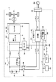
- FIG. 1 is an overall block diagram of a vehicle 1 equipped with a charging device according to the present embodiment.
- the vehicle 1 includes a main battery 10, a system main relay (hereinafter referred to as "SMR") 11, a power control unit (hereinafter referred to as “PCU”) 20, a motor generator (hereinafter referred to as “MG”) 30, a power transmission gear. 40, drive wheels 50, auxiliary battery 60, auxiliary load 70, charging unit 80, and control device (hereinafter referred to as “ECU”) 100.
- SMR system main relay
- PCU power control unit
- MG motor generator
- ECU control device
- the MG 30 is an AC rotating electric machine that generates a driving force for driving the vehicle 1.
- the output torque of the MG 30 is transmitted to the drive wheels 50 via the power transmission gear 40 and causes the vehicle 1 to travel.
- the MG 30 can generate power by the rotational force of the drive wheels 50 during regenerative braking of the vehicle 1.
- the generated electric power is converted into electric power for charging the main battery 10 by the PCU 20.
- FIG. 1 illustrates the case where one MG 30 is provided, a plurality of motor generators may be provided.
- the main battery 10 is a direct current power source that stores electric power for operating the MG 30.
- the main battery 10 is a secondary battery such as a lithium ion battery or a nickel metal hydride battery.
- the main battery 10 may be an electric double layer capacitor.
- the main battery 10 is connected to the boost converter 21 of the PCU 20 via the positive line PL1 and the negative line NL1. Then, the main battery 10 supplies power for operating the MG 30 to the PCU 20.
- the voltage of the main battery 10 is a relatively high value of about 200 volts, for example.
- the SMR 11 is controlled by a control signal S1 from the ECU 100, and switches between power supply and cutoff between the main battery 10 and the PCU 20.
- the PCU 20 includes a boost converter 21, an inverter 22, and a DC / DC converter 23.
- Boost converter 21 is controlled by a control signal S2 from ECU 100, converts the voltage of main battery 10 into a voltage equal to or higher than the voltage of main battery 10, and supplies the voltage to inverter 22.
- the inverter 22 is controlled by a control signal S3 from the ECU 100, converts the DC power supplied from the main battery 10 via the boost converter 21 into AC power that can operate the MG 30, and supplies the AC power to the MG 30. As a result, the MG 30 is operated by the power of the main battery 10.
- the DC / DC converter 23 is controlled based on a control signal S4 from the ECU 100, and converts the voltage between the positive line PL1 and the negative line NL1 (that is, the high voltage of the main battery 10) to the voltage of the auxiliary battery 60 (12 volts). And then supplied to the auxiliary battery 60 via the power line L1. Thereby, auxiliary battery 60 is charged with the power of main battery 10.
- the auxiliary battery 60 typically includes a lead storage battery.
- the auxiliary battery 60 is a direct current power source that stores electric power for operating auxiliary devices (such as the auxiliary load 70 and the ECU 100) of the vehicle 1.
- the voltage of the auxiliary battery 60 is a relatively low value of about 12 volts as described above.
- the auxiliary battery 60 and the electric devices that operate with the electric power of the auxiliary battery 60 are also collectively referred to as a “low voltage system”.
- the auxiliary load 70 is a low-voltage electric device.
- the auxiliary machine load 70 is composed of, for example, an air conditioning unit, an audio unit, lamps, a wiper, a heater and the like.
- vehicle 1 has a charging unit 80, an inlet 83, and a charging relay as a configuration for performing external charging for charging main battery 10 with AC power from external power supply 500 (hereinafter also referred to as “external power”). 84.
- the inlet 83 is provided in the body of the vehicle 1 in order to receive AC power from the external power source 500.
- the inlet 83 is configured so that a connector of the external power supply 500 can be connected.
- Charging unit 80 includes a charger 81 and a sub power source 82.
- Charger 81 is connected to main battery 10 via positive line PL2 and negative line NL2, and is connected to inlet 83 via positive line PL3 and negative line NL3.
- the charger 81 is controlled by a control signal S5 from the ECU 100 and converts external power (AC power) input to the inlet 83 into power (DC 200 volts) that can be charged to the main battery 10. Supply. Thereby, external charging is performed.
- the sub power source 82 is a power converter provided between the charger 81 and the auxiliary battery 60.
- the sub power source 82 is external power supplied from the inlet 83 to the charger 81 (even if it is AC power before the external power is converted by the charger 81, DC power after the external power is converted by the charger 81).
- DC power supplied from the main battery 10 to the charger 81 can be converted into power that can be supplied to the low voltage system (DC 12 volts or so).
- the electric power converted by the sub power source 82 is supplied to the low voltage system via the power line L2.
- the sub power source 82 functions as a power source for supplying power to the low voltage system during external charging. That is, during external charging, the SMR 11 is turned off as will be described later, and power cannot be supplied from the DC / DC converter 23 to the auxiliary battery 60. Therefore, power is supplied from the sub power source 82 to the low voltage system during external charging.
- the capacity (rated power) of the sub power supply 82 is set to a value smaller than the capacity of the DC / DC converter 23. That is, while the vehicle is running, the power consumption of the low voltage system tends to increase because the user uses air conditioning or audio. Since the DC / DC converter 23 mainly supplies power to the low voltage system while the vehicle is running, the capacity of the DC / DC converter 23 is set to a large value (for example, about 2 kilowatts). On the other hand, during external charging, the user rarely uses air conditioning, audio, or the like, and the power consumption of the low-voltage system tends to be lower than during vehicle traveling. Since the sub power supply 82 mainly supplies power to the low voltage system during external charging, the capacity of the sub power supply 82 is smaller than the capacity of the DC / DC converter 23 in consideration of conversion efficiency (for example, 200 watts). Degree).
- the charging relay 84 is controlled by a control signal S7 from the ECU 100, and switches between supply and interruption of power between the main battery 10 and the charger 81.
- the vehicle 1 has a plurality of sensors that detect information necessary for controlling the traveling of the vehicle 1 such as the state (voltage, current, temperature, etc.) of the main battery 10 and the auxiliary battery 60, the accelerator pedal position, and the vehicle speed. (Both not shown). Each sensor outputs a detection result to ECU 100.
- the ECU 100 includes a CPU (Central Processing Unit) and a memory, generates the control signals S1 to S7 described above according to information stored in the memory, detection results of each sensor, and the like, and outputs them to corresponding devices.
- ECU 100 is a single unit, but it may be divided for each function.
- ECU100 turns on the charging relay 84 and connects the charging path of the main battery 10 and the charging unit 80, when performing external charging. Then, ECU 100 operates charger 81 to convert external power into power that can be charged in main battery 10, and supplies it to main battery 10. At this time, the ECU 100 turns off the SMR 11 in consideration of the life of the PCU 20 (that is, shuts off the energization path between the main battery 10 and the PCU 20).
- the ECU 100 operates the sub power source 82 to convert external power into power that can be supplied to the low voltage system, and supplies it to the low voltage system.
- the low voltage system which needs to be operated during external charging can be operated using the external power, and the power consumption of the auxiliary battery 60 can be suppressed.
- power can be supplied from the sub power source 82 to the low voltage system in addition to the auxiliary battery 60.
- the ECU 100 controls the PCU 20 with the SMR 11 turned on, thereby operating the MG 30 with the electric power of the main battery 10.
- the ECU 100 activates the DC / DC converter 23 or activates the sub-power supply 82 by turning on the charging relay 84 when the voltage (charged amount) of the auxiliary battery 60 falls below the target value. Then, the auxiliary battery 60 is charged.
- the DC / DC converter 23 functions as a main converter
- the sub power source 82 functions as a sub converter.
- FIG. 2 is a diagram showing an image of the energy (power consumption) balance of the low voltage system during one trip.
- the output possible energy of the auxiliary battery 60 during one trip is “P1”
- the convertible energy of the sub power source 82 during one trip is “P2”
- the convertible energy of the DC / DC converter 23 during one trip is “P3”.
- the low-voltage consumable energy Pnor during one trip when the DC / DC converter 23 operates normally (hereinafter also simply referred to as “normal time”) is a value obtained by adding P1, P2, and P3. It becomes.
- the low-voltage system consumable energy “Pavern” during one trip is a value obtained by adding P1 and P2, and is normal. It is lower than P3 by P3. If this consumable energy “Pavern” has not reached the required energy P0 of the low voltage system during one trip, the power of the low voltage system is insufficient during the trip and the auxiliary battery 60 may be overdischarged. There is. In particular, since the capacity of the sub power supply 82 is as small as about 200 watts and the convertible energy P2 cannot be sufficiently secured, the possibility of shortage of low-voltage power increases.
- the ECU 100 determines whether or not the DC / DC converter 23 is abnormal at the end of the external charging, and when it is abnormal, the auxiliary power source 82 is operated as necessary to activate the auxiliary machine before the start of traveling.
- the voltage of the battery 60 is set higher than normal.
- such charging of the auxiliary battery 60 is also referred to as “preliminary charging”. This precharging is the most characteristic point of this embodiment.
- FIG. 3 is a functional block diagram of the ECU 100 relating to the preliminary charging. Each functional block shown in FIG. 3 may be realized by hardware or software.
- ECU 100 includes a determination unit 110, calculation units 120 and 130, a comparison unit 140, and a control unit 150.
- the determination unit 110 determines whether or not the DC / DC converter 23 is abnormal at the end of external charging (when the charged amount of the main battery 10 reaches a target value due to external charging). This determination may be made based on, for example, whether or not there is a history indicating that the DC / DC converter 23 has failed in the previous trip, or the SMR 11 is actually connected to the DC / DC converter 23. You may perform based on the result when operating.
- the calculation unit 130 calculates the output possible energy P1 of the auxiliary battery 60 during the next trip and the convertible energy P2 of the sub power source 82 during the next trip. Since the charged amount of the auxiliary battery 60 has a positive correlation with the voltage of the auxiliary battery 60, the output possible energy P1 of the auxiliary battery 60 during the next trip is calculated based on the voltage of the auxiliary battery 60, for example. Good. Further, the convertible energy P2 of the sub power source 82 during the next trip may be predicted based on, for example, the capacity (200 watts) of the sub power source 82 and the next trip time. The next trip time may be predicted from, for example, the distance to the destination, the degree of road congestion, or the average value of the past one trip time. Note that the calculation methods of P1 and P2 are not limited to these methods.
- calculation part 130 calculates the sum total energy of the output possible energy P1 of the auxiliary
- the comparison unit 140 compares the necessary energy P0 and the consumable energy Pavern, and outputs the result to the control unit 150.
- the control unit 150 controls the sub power supply 82 based on the comparison result from the comparison unit 140.
- Control unit 150 generates control signal S6 for performing preliminary charging and outputs it to sub power supply 82 when consumable energy Pavern is smaller than required energy P0.
- the control unit 150 stops the preliminary charging when the consumable energy Pavern reaches the required energy P0.
- FIG. 4 compares the auxiliary battery voltage V1 before the start of traveling when the preliminary charging is not performed (normal time) and the auxiliary battery voltage V2 before the starting of the traveling when preliminary charging is performed (when abnormal).
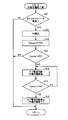
- step 10 the ECU 100 determines whether the DC / DC converter 23 is abnormal. If DC / DC converter 23 is abnormal (YES in S10), the process proceeds to S11. Otherwise (NO in S10), the process is terminated.
- the ECU 100 calculates the required energy P0 of the low voltage system during the next trip.
- ECU 100 calculates the total energy of output possible energy P1 of auxiliary battery 60 during the next trip and convertible energy P2 of sub power supply 82 during the next trip of the low voltage system during the next trip during an abnormality. It is calculated as a consumable energy Pavern.
- the ECU 100 determines whether or not the consumable energy “Pavern” calculated in S12 is greater than the necessary energy P0 calculated in S11 (whether or not “Pavern> P0”). If Panel> P0 (YES in S13), this process ends. If Pavern ⁇ P0 (NO in S13), the process proceeds to S14.
- ECU 100 operates sub power supply 82 to start preliminary charging.
- ECU 100 determines whether or not consumable energy Pavern has become larger than required energy P0 due to the preliminary charging. If consumable energy Pavern is still smaller than required energy P0 (NO in S15), the process returns to S14, and the preliminary charging is continued.
Landscapes
- Engineering & Computer Science (AREA)
- Power Engineering (AREA)
- Transportation (AREA)
- Mechanical Engineering (AREA)
- Life Sciences & Earth Sciences (AREA)
- Sustainable Development (AREA)
- Sustainable Energy (AREA)
- Electric Propulsion And Braking For Vehicles (AREA)
- Charge And Discharge Circuits For Batteries Or The Like (AREA)
Abstract
Description
充電器81は、正極線PL2および負極線NL2を介してメインバッテリ10に接続されるとともに、正極線PL3および負極線NL3を介してインレット83に接続される。充電器81は、ECU100からの制御信号S5によって制御され、インレット83に入力された外部電力(交流電力)を、メインバッテリ10に充電可能な電力(直流200ボルト)に変換し、メインバッテリ10に供給する。これにより外部充電が行なわれる。
S15にて、ECU100は、予備充電によって消費可能エネルギPabnorが必要エネルギP0よりも大きくなったか否かを判断する。消費可能エネルギPabnorが未だ必要エネルギP0よりも小さい場合(S15にてNO)、処理はS14に戻され、予備充電が継続される。
Claims (6)
- 車両駆動用の電動機(30)を作動させるための電力を蓄える第1電源(10)と、車両の補機(70)を作動させるための電力を蓄える第2電源(60)と、車両の外部電源(500)と接続可能に構成されたコネクタ(83)とを備えた車両の充電装置であって、
前記第1電源と前記電動機との間の通電経路上の電力を変換して前記第2電源へ供給する第1変換器(23)と、
前記第1電源と前記コネクタとの間の通電経路上の電力を変換して前記第2電源へ供給する、前記第1変換器よりも容量が小さい第2変換器(82)と、
前記第2変換器を制御する制御装置(100)とを備え、
前記制御装置は、前記第1変換器が異常である場合、前記第1変換器が正常である場合よりも前記第2電源の電圧または蓄電量が大きくなるように前記第2変換器を作動させる予備充電を行なう、車両の充電装置。 - 前記制御装置は、前記車両の停止中に前記外部電源が前記コネクタに接続された状態で前記第1変換器が異常であるか否かを判定し、前記第1変換器が異常であると判定された場合に前記車両の走行開始前に前記予備充電を行なう、請求の範囲第1項に記載の車両の充電装置。
- 前記制御装置は、前記車両の停止中に前記第1変換器が異常であると判定された場合であって、かつ1トリップ中の前記第2電源の出力可能エネルギと1トリップ中の前記第2変換器の変換可能エネルギとの合計エネルギが1トリップ中の前記補機の必要エネルギよりも小さいと予測される場合に、前記予備充電を行なう、請求の範囲第2項に記載の車両の充電装置。
- 前記制御装置は、前記予備充電によって前記合計エネルギが前記必要エネルギよりも大きくなった時点で前記予備充電を停止する、請求の範囲第3項に記載の車両の充電装置。
- 前記制御装置は、前記予備充電によって前記第2電源の電圧または蓄電量が予め定められた値に達した時点で前記予備充電を停止する、請求の範囲第2項に記載の車両の充電装置。
- 前記車両は、前記第1電源と前記コネクタとの間の通電経路上に設けられ前記外部電源の電力を前記第1電源に充電可能な電力に変換する充電器(81)をさらに備え、
前記第2変換器は、前記充電器と前記第2電源との間に設けられる、請求の範囲第1項に記載の車両の充電装置。
Priority Applications (5)
| Application Number | Priority Date | Filing Date | Title |
|---|---|---|---|
| EP10859842.6A EP2641771B1 (en) | 2010-11-19 | 2010-11-19 | Vehicle charging device |
| CN201080070219.9A CN103221246B (zh) | 2010-11-19 | 2010-11-19 | 车辆的充电装置 |
| US13/876,599 US8742718B2 (en) | 2010-11-19 | 2010-11-19 | Charging apparatus for vehicle |
| PCT/JP2010/070684 WO2012066675A1 (ja) | 2010-11-19 | 2010-11-19 | 車両の充電装置 |
| JP2012544065A JP5310959B2 (ja) | 2010-11-19 | 2010-11-19 | 車両の充電装置 |
Applications Claiming Priority (1)
| Application Number | Priority Date | Filing Date | Title |
|---|---|---|---|
| PCT/JP2010/070684 WO2012066675A1 (ja) | 2010-11-19 | 2010-11-19 | 車両の充電装置 |
Publications (1)
| Publication Number | Publication Date |
|---|---|
| WO2012066675A1 true WO2012066675A1 (ja) | 2012-05-24 |
Family
ID=46083633
Family Applications (1)
| Application Number | Title | Priority Date | Filing Date |
|---|---|---|---|
| PCT/JP2010/070684 Ceased WO2012066675A1 (ja) | 2010-11-19 | 2010-11-19 | 車両の充電装置 |
Country Status (5)
| Country | Link |
|---|---|
| US (1) | US8742718B2 (ja) |
| EP (1) | EP2641771B1 (ja) |
| JP (1) | JP5310959B2 (ja) |
| CN (1) | CN103221246B (ja) |
| WO (1) | WO2012066675A1 (ja) |
Cited By (8)
| Publication number | Priority date | Publication date | Assignee | Title |
|---|---|---|---|---|
| CN103847531A (zh) * | 2012-11-28 | 2014-06-11 | 北汽福田汽车股份有限公司 | 一种电动汽车高压电气系统及控制方法 |
| JP2015180138A (ja) * | 2014-03-19 | 2015-10-08 | トヨタ自動車株式会社 | 車載充電システム |
| CN106183822A (zh) * | 2015-05-26 | 2016-12-07 | 福特全球技术公司 | 电动车辆高电压系统警报 |
| JP2017069160A (ja) * | 2015-10-02 | 2017-04-06 | 株式会社デンソー | 充電装置及び充電方法 |
| CN107933314A (zh) * | 2016-10-13 | 2018-04-20 | 丰田自动车株式会社 | 电力供给系统 |
| JP2019198157A (ja) * | 2018-05-08 | 2019-11-14 | トヨタ自動車株式会社 | 車両の充電システム |
| JP2020124072A (ja) * | 2019-01-31 | 2020-08-13 | トヨタ自動車株式会社 | 車両 |
| JP2021090278A (ja) * | 2019-12-04 | 2021-06-10 | トヨタ自動車株式会社 | 車両および車両の制御方法 |
Families Citing this family (23)
| Publication number | Priority date | Publication date | Assignee | Title |
|---|---|---|---|---|
| US8841881B2 (en) | 2010-06-02 | 2014-09-23 | Bryan Marc Failing | Energy transfer with vehicles |
| US20150097501A1 (en) * | 2013-10-04 | 2015-04-09 | Samsung Sdi Co., Ltd. | Electric vehicle power conversion system |
| JP5862631B2 (ja) * | 2013-10-08 | 2016-02-16 | トヨタ自動車株式会社 | 蓄電システム |
| JP6171885B2 (ja) * | 2013-11-20 | 2017-08-02 | 株式会社デンソー | 車載電気システム |
| NL2012027C2 (en) * | 2013-12-24 | 2015-06-26 | E Traction Europe Bv | Power converter for electric vehicle. |
| WO2015104287A1 (en) * | 2014-01-10 | 2015-07-16 | Alphalys Holdings Sa | Power supply for a load |
| KR102302783B1 (ko) * | 2014-07-25 | 2021-09-16 | 현대모비스 주식회사 | 차량 구동 시스템 및 방법 |
| US9923470B2 (en) | 2015-09-18 | 2018-03-20 | Lear Corporation | High voltage pre-charge system |
| JP6394998B2 (ja) * | 2016-02-15 | 2018-09-26 | トヨタ自動車株式会社 | 二次電池切り離し方法 |
| JP6458756B2 (ja) * | 2016-03-22 | 2019-01-30 | トヨタ自動車株式会社 | 自動車 |
| JP6553556B2 (ja) * | 2016-08-08 | 2019-07-31 | トヨタ自動車株式会社 | 自動車 |
| WO2018229863A1 (ja) * | 2017-06-13 | 2018-12-20 | 株式会社東芝 | 鉄道車両 |
| DE102018203263A1 (de) * | 2018-03-06 | 2019-09-12 | Audi Ag | Ladeeinrichtung für ein Kraftfahrzeug |
| JP6974234B2 (ja) * | 2018-03-30 | 2021-12-01 | 本田技研工業株式会社 | 車両の電源システム |
| CN109193833B (zh) * | 2018-09-13 | 2020-08-07 | 中国汽车工程研究院股份有限公司 | 一种新能源汽车低压蓄电池补电电路工作方法 |
| JP6907175B2 (ja) * | 2018-11-20 | 2021-07-21 | 矢崎総業株式会社 | 電源システム |
| CN109649373A (zh) * | 2018-12-19 | 2019-04-19 | 安徽江淮汽车集团股份有限公司 | 一种混合动力汽车车载12v电源充电电压设定值控制方法 |
| JP7229820B2 (ja) * | 2019-03-15 | 2023-02-28 | 本田技研工業株式会社 | 電力制御装置 |
| US11052783B2 (en) * | 2019-06-06 | 2021-07-06 | GM Global Technology Operations LLC | Control of device having multiple rechargeable packs with different capacities for optimal energy delivery |
| EP3988819A4 (en) * | 2019-06-21 | 2022-08-03 | JATCO Ltd | POWER SUPPLY DEVICE FOR A VEHICLE AND CONTROL METHOD THEREOF |
| JP7464006B2 (ja) * | 2021-06-02 | 2024-04-09 | トヨタ自動車株式会社 | 充電システム、充電器、および、充電システムの制御方法 |
| CN114825581B (zh) * | 2021-06-30 | 2025-01-24 | 长城汽车股份有限公司 | 车辆低压电网异常处理方法、装置、车辆及计算机可读存储介质 |
| WO2024156045A1 (pt) * | 2023-01-27 | 2024-08-02 | Castertech Fundição E Tecnologia Ltda | Sistema e processo de carregamento e descarregamento de armazenador de energia elétrica, conector e veículo |
Citations (5)
| Publication number | Priority date | Publication date | Assignee | Title |
|---|---|---|---|---|
| JPH08107606A (ja) * | 1994-10-03 | 1996-04-23 | Honda Motor Co Ltd | 電動車両用充電装置 |
| JP2007089328A (ja) * | 2005-09-22 | 2007-04-05 | Toyota Motor Corp | 電力変換機構の異常検知装置 |
| JP2009225587A (ja) | 2008-03-17 | 2009-10-01 | Toyota Motor Corp | 電動車両 |
| JP2010093891A (ja) * | 2008-10-06 | 2010-04-22 | Fujitsu Ten Ltd | 電子制御装置、プラグイン車両、及び給電経路切替方法 |
| JP2010279159A (ja) * | 2009-05-28 | 2010-12-09 | Toyota Motor Corp | 電動車両の電源システム |
Family Cites Families (11)
| Publication number | Priority date | Publication date | Assignee | Title |
|---|---|---|---|---|
| JPH07250405A (ja) * | 1994-03-11 | 1995-09-26 | Fujitsu Denso Ltd | 電気自動車用充電装置 |
| JPH0865904A (ja) * | 1994-06-06 | 1996-03-08 | Nippondenso Co Ltd | 電気自動車用充電装置 |
| US6784565B2 (en) * | 1997-09-08 | 2004-08-31 | Capstone Turbine Corporation | Turbogenerator with electrical brake |
| KR100258043B1 (ko) * | 1997-10-27 | 2000-06-01 | 에릭 발리베 | 복합전기자동차용 보조동력장치의 제어시스템 |
| JP3625789B2 (ja) * | 2001-08-10 | 2005-03-02 | 本田技研工業株式会社 | 車両の電源装置 |
| JP2006217743A (ja) * | 2005-02-04 | 2006-08-17 | Toyota Motor Corp | 電気負荷制御装置 |
| JP4379441B2 (ja) * | 2006-07-18 | 2009-12-09 | トヨタ自動車株式会社 | 電源システムおよびそれを備えた車両、蓄電装置の昇温制御方法、ならびに蓄電装置の昇温制御をコンピュータに実行させるためのプログラムを記録したコンピュータ読取可能な記録媒体 |
| JP4144646B1 (ja) * | 2007-02-20 | 2008-09-03 | トヨタ自動車株式会社 | 電動車両、車両充電装置および車両充電システム |
| CN101682208B (zh) * | 2007-06-11 | 2012-06-13 | 丰田自动车株式会社 | 电气系统的控制装置及控制方法 |
| JP4407747B2 (ja) * | 2007-12-13 | 2010-02-03 | ソニー株式会社 | A/d変換器及び情報記録再生装置 |
| US7929323B2 (en) * | 2008-09-26 | 2011-04-19 | Rockwell Automation Technologies, Inc. | Method and apparatus for pre-charging power converters and diagnosing pre-charge faults |
-
2010
- 2010-11-19 CN CN201080070219.9A patent/CN103221246B/zh not_active Expired - Fee Related
- 2010-11-19 WO PCT/JP2010/070684 patent/WO2012066675A1/ja not_active Ceased
- 2010-11-19 US US13/876,599 patent/US8742718B2/en not_active Expired - Fee Related
- 2010-11-19 JP JP2012544065A patent/JP5310959B2/ja not_active Expired - Fee Related
- 2010-11-19 EP EP10859842.6A patent/EP2641771B1/en active Active
Patent Citations (5)
| Publication number | Priority date | Publication date | Assignee | Title |
|---|---|---|---|---|
| JPH08107606A (ja) * | 1994-10-03 | 1996-04-23 | Honda Motor Co Ltd | 電動車両用充電装置 |
| JP2007089328A (ja) * | 2005-09-22 | 2007-04-05 | Toyota Motor Corp | 電力変換機構の異常検知装置 |
| JP2009225587A (ja) | 2008-03-17 | 2009-10-01 | Toyota Motor Corp | 電動車両 |
| JP2010093891A (ja) * | 2008-10-06 | 2010-04-22 | Fujitsu Ten Ltd | 電子制御装置、プラグイン車両、及び給電経路切替方法 |
| JP2010279159A (ja) * | 2009-05-28 | 2010-12-09 | Toyota Motor Corp | 電動車両の電源システム |
Non-Patent Citations (1)
| Title |
|---|
| See also references of EP2641771A4 * |
Cited By (13)
| Publication number | Priority date | Publication date | Assignee | Title |
|---|---|---|---|---|
| CN103847531B (zh) * | 2012-11-28 | 2016-06-08 | 北汽福田汽车股份有限公司 | 一种电动汽车高压电气系统及控制方法 |
| CN103847531A (zh) * | 2012-11-28 | 2014-06-11 | 北汽福田汽车股份有限公司 | 一种电动汽车高压电气系统及控制方法 |
| JP2015180138A (ja) * | 2014-03-19 | 2015-10-08 | トヨタ自動車株式会社 | 車載充電システム |
| CN106183822A (zh) * | 2015-05-26 | 2016-12-07 | 福特全球技术公司 | 电动车辆高电压系统警报 |
| JP2017069160A (ja) * | 2015-10-02 | 2017-04-06 | 株式会社デンソー | 充電装置及び充電方法 |
| CN107933314B (zh) * | 2016-10-13 | 2020-09-25 | 丰田自动车株式会社 | 电力供给系统 |
| CN107933314A (zh) * | 2016-10-13 | 2018-04-20 | 丰田自动车株式会社 | 电力供给系统 |
| JP2019198157A (ja) * | 2018-05-08 | 2019-11-14 | トヨタ自動車株式会社 | 車両の充電システム |
| JP7043964B2 (ja) | 2018-05-08 | 2022-03-30 | トヨタ自動車株式会社 | 車両の充電システム |
| JP2020124072A (ja) * | 2019-01-31 | 2020-08-13 | トヨタ自動車株式会社 | 車両 |
| JP7131413B2 (ja) | 2019-01-31 | 2022-09-06 | トヨタ自動車株式会社 | 車両 |
| JP2021090278A (ja) * | 2019-12-04 | 2021-06-10 | トヨタ自動車株式会社 | 車両および車両の制御方法 |
| JP7205451B2 (ja) | 2019-12-04 | 2023-01-17 | トヨタ自動車株式会社 | 車両および車両の制御方法 |
Also Published As
| Publication number | Publication date |
|---|---|
| EP2641771B1 (en) | 2017-04-19 |
| CN103221246B (zh) | 2015-07-15 |
| JPWO2012066675A1 (ja) | 2014-05-12 |
| EP2641771A1 (en) | 2013-09-25 |
| JP5310959B2 (ja) | 2013-10-09 |
| US8742718B2 (en) | 2014-06-03 |
| EP2641771A4 (en) | 2015-06-03 |
| US20130221920A1 (en) | 2013-08-29 |
| CN103221246A (zh) | 2013-07-24 |
Similar Documents
| Publication | Publication Date | Title |
|---|---|---|
| JP5310959B2 (ja) | 車両の充電装置 | |
| JP6269663B2 (ja) | 車載太陽電池を利用する充電制御装置 | |
| JP4788842B2 (ja) | ハイブリッド車両の制御装置および制御方法 | |
| JP7176852B2 (ja) | 車両電源システム | |
| JP7158166B2 (ja) | 車両電源システム | |
| US20090315518A1 (en) | Power supply device and vehicle | |
| JP7068893B2 (ja) | 車両電源システム | |
| JP7081959B2 (ja) | 車両電源システム | |
| JP7020144B2 (ja) | 電動車両及び電動車両の制御方法 | |
| CN103339005A (zh) | 混合动力车辆 | |
| JP7081958B2 (ja) | 車両電源システム | |
| JP2012085481A (ja) | 電動車両 | |
| CN102632809A (zh) | 电动汽车和控制有功辅助电池损耗的方法 | |
| JP7149093B2 (ja) | 車両電源システム | |
| JP2010273417A (ja) | 電動車両 | |
| JP7096046B2 (ja) | 車両電源システム | |
| CN102334260A (zh) | 车辆控制装置及控制方法 | |
| JP4915273B2 (ja) | 電気機器および電気機器の制御方法 | |
| JP5675561B2 (ja) | 電気自動車 | |
| JP5625715B2 (ja) | 車両の制御装置および制御方法 | |
| JP2015035919A (ja) | 車両および車両の制御方法 | |
| JP2015057009A (ja) | 車両 | |
| EP2765670B1 (en) | Electric vehicle power supply system and method for controlling same | |
| WO2011158088A2 (en) | Electric power supply apparatus for vehicle, and control method thereof | |
| JP5243571B2 (ja) | ハイブリッド車両の制御装置 |
Legal Events
| Date | Code | Title | Description |
|---|---|---|---|
| 121 | Ep: the epo has been informed by wipo that ep was designated in this application |
Ref document number: 10859842 Country of ref document: EP Kind code of ref document: A1 |
|
| WWE | Wipo information: entry into national phase |
Ref document number: 13876599 Country of ref document: US |
|
| ENP | Entry into the national phase |
Ref document number: 2012544065 Country of ref document: JP Kind code of ref document: A |
|
| REEP | Request for entry into the european phase |
Ref document number: 2010859842 Country of ref document: EP |
|
| WWE | Wipo information: entry into national phase |
Ref document number: 2010859842 Country of ref document: EP |
|
| NENP | Non-entry into the national phase |
Ref country code: DE |