WO2012066934A1 - 電動車両の充電制御装置 - Google Patents
電動車両の充電制御装置 Download PDFInfo
- Publication number
- WO2012066934A1 WO2012066934A1 PCT/JP2011/075278 JP2011075278W WO2012066934A1 WO 2012066934 A1 WO2012066934 A1 WO 2012066934A1 JP 2011075278 W JP2011075278 W JP 2011075278W WO 2012066934 A1 WO2012066934 A1 WO 2012066934A1
- Authority
- WO
- WIPO (PCT)
- Prior art keywords
- charging
- battery
- charger
- traveling
- electric vehicle
- Prior art date
- Legal status (The legal status is an assumption and is not a legal conclusion. Google has not performed a legal analysis and makes no representation as to the accuracy of the status listed.)
- Ceased
Links
Images


Classifications
-
- B—PERFORMING OPERATIONS; TRANSPORTING
- B60—VEHICLES IN GENERAL
- B60L—PROPULSION OF ELECTRICALLY-PROPELLED VEHICLES; SUPPLYING ELECTRIC POWER FOR AUXILIARY EQUIPMENT OF ELECTRICALLY-PROPELLED VEHICLES; ELECTRODYNAMIC BRAKE SYSTEMS FOR VEHICLES IN GENERAL; MAGNETIC SUSPENSION OR LEVITATION FOR VEHICLES; MONITORING OPERATING VARIABLES OF ELECTRICALLY-PROPELLED VEHICLES; ELECTRIC SAFETY DEVICES FOR ELECTRICALLY-PROPELLED VEHICLES
- B60L53/00—Methods of charging batteries, specially adapted for electric vehicles; Charging stations or on-board charging equipment therefor; Exchange of energy storage elements in electric vehicles
- B60L53/10—Methods of charging batteries, specially adapted for electric vehicles; Charging stations or on-board charging equipment therefor; Exchange of energy storage elements in electric vehicles characterised by the energy transfer between the charging station and the vehicle
- B60L53/14—Conductive energy transfer
-
- B—PERFORMING OPERATIONS; TRANSPORTING
- B60—VEHICLES IN GENERAL
- B60L—PROPULSION OF ELECTRICALLY-PROPELLED VEHICLES; SUPPLYING ELECTRIC POWER FOR AUXILIARY EQUIPMENT OF ELECTRICALLY-PROPELLED VEHICLES; ELECTRODYNAMIC BRAKE SYSTEMS FOR VEHICLES IN GENERAL; MAGNETIC SUSPENSION OR LEVITATION FOR VEHICLES; MONITORING OPERATING VARIABLES OF ELECTRICALLY-PROPELLED VEHICLES; ELECTRIC SAFETY DEVICES FOR ELECTRICALLY-PROPELLED VEHICLES
- B60L50/00—Electric propulsion with power supplied within the vehicle
- B60L50/50—Electric propulsion with power supplied within the vehicle using propulsion power supplied by batteries or fuel cells
- B60L50/51—Electric propulsion with power supplied within the vehicle using propulsion power supplied by batteries or fuel cells characterised by AC-motors
-
- B—PERFORMING OPERATIONS; TRANSPORTING
- B60—VEHICLES IN GENERAL
- B60L—PROPULSION OF ELECTRICALLY-PROPELLED VEHICLES; SUPPLYING ELECTRIC POWER FOR AUXILIARY EQUIPMENT OF ELECTRICALLY-PROPELLED VEHICLES; ELECTRODYNAMIC BRAKE SYSTEMS FOR VEHICLES IN GENERAL; MAGNETIC SUSPENSION OR LEVITATION FOR VEHICLES; MONITORING OPERATING VARIABLES OF ELECTRICALLY-PROPELLED VEHICLES; ELECTRIC SAFETY DEVICES FOR ELECTRICALLY-PROPELLED VEHICLES
- B60L53/00—Methods of charging batteries, specially adapted for electric vehicles; Charging stations or on-board charging equipment therefor; Exchange of energy storage elements in electric vehicles
- B60L53/10—Methods of charging batteries, specially adapted for electric vehicles; Charging stations or on-board charging equipment therefor; Exchange of energy storage elements in electric vehicles characterised by the energy transfer between the charging station and the vehicle
- B60L53/11—DC charging controlled by the charging station, e.g. mode 4
-
- B—PERFORMING OPERATIONS; TRANSPORTING
- B60—VEHICLES IN GENERAL
- B60L—PROPULSION OF ELECTRICALLY-PROPELLED VEHICLES; SUPPLYING ELECTRIC POWER FOR AUXILIARY EQUIPMENT OF ELECTRICALLY-PROPELLED VEHICLES; ELECTRODYNAMIC BRAKE SYSTEMS FOR VEHICLES IN GENERAL; MAGNETIC SUSPENSION OR LEVITATION FOR VEHICLES; MONITORING OPERATING VARIABLES OF ELECTRICALLY-PROPELLED VEHICLES; ELECTRIC SAFETY DEVICES FOR ELECTRICALLY-PROPELLED VEHICLES
- B60L53/00—Methods of charging batteries, specially adapted for electric vehicles; Charging stations or on-board charging equipment therefor; Exchange of energy storage elements in electric vehicles
- B60L53/60—Monitoring or controlling charging stations
- B60L53/64—Optimising energy costs, e.g. responding to electricity rates
-
- B—PERFORMING OPERATIONS; TRANSPORTING
- B60—VEHICLES IN GENERAL
- B60L—PROPULSION OF ELECTRICALLY-PROPELLED VEHICLES; SUPPLYING ELECTRIC POWER FOR AUXILIARY EQUIPMENT OF ELECTRICALLY-PROPELLED VEHICLES; ELECTRODYNAMIC BRAKE SYSTEMS FOR VEHICLES IN GENERAL; MAGNETIC SUSPENSION OR LEVITATION FOR VEHICLES; MONITORING OPERATING VARIABLES OF ELECTRICALLY-PROPELLED VEHICLES; ELECTRIC SAFETY DEVICES FOR ELECTRICALLY-PROPELLED VEHICLES
- B60L58/00—Methods or circuit arrangements for monitoring or controlling batteries or fuel cells, specially adapted for electric vehicles
- B60L58/10—Methods or circuit arrangements for monitoring or controlling batteries or fuel cells, specially adapted for electric vehicles for monitoring or controlling batteries
- B60L58/12—Methods or circuit arrangements for monitoring or controlling batteries or fuel cells, specially adapted for electric vehicles for monitoring or controlling batteries responding to state of charge [SoC]
- B60L58/15—Preventing overcharging
-
- B—PERFORMING OPERATIONS; TRANSPORTING
- B60—VEHICLES IN GENERAL
- B60L—PROPULSION OF ELECTRICALLY-PROPELLED VEHICLES; SUPPLYING ELECTRIC POWER FOR AUXILIARY EQUIPMENT OF ELECTRICALLY-PROPELLED VEHICLES; ELECTRODYNAMIC BRAKE SYSTEMS FOR VEHICLES IN GENERAL; MAGNETIC SUSPENSION OR LEVITATION FOR VEHICLES; MONITORING OPERATING VARIABLES OF ELECTRICALLY-PROPELLED VEHICLES; ELECTRIC SAFETY DEVICES FOR ELECTRICALLY-PROPELLED VEHICLES
- B60L58/00—Methods or circuit arrangements for monitoring or controlling batteries or fuel cells, specially adapted for electric vehicles
- B60L58/10—Methods or circuit arrangements for monitoring or controlling batteries or fuel cells, specially adapted for electric vehicles for monitoring or controlling batteries
- B60L58/18—Methods or circuit arrangements for monitoring or controlling batteries or fuel cells, specially adapted for electric vehicles for monitoring or controlling batteries of two or more battery modules
- B60L58/20—Methods or circuit arrangements for monitoring or controlling batteries or fuel cells, specially adapted for electric vehicles for monitoring or controlling batteries of two or more battery modules having different nominal voltages
-
- H—ELECTRICITY
- H01—ELECTRIC ELEMENTS
- H01M—PROCESSES OR MEANS, e.g. BATTERIES, FOR THE DIRECT CONVERSION OF CHEMICAL ENERGY INTO ELECTRICAL ENERGY
- H01M10/00—Secondary cells; Manufacture thereof
- H01M10/42—Methods or arrangements for servicing or maintenance of secondary cells or secondary half-cells
- H01M10/44—Methods for charging or discharging
-
- H—ELECTRICITY
- H01—ELECTRIC ELEMENTS
- H01M—PROCESSES OR MEANS, e.g. BATTERIES, FOR THE DIRECT CONVERSION OF CHEMICAL ENERGY INTO ELECTRICAL ENERGY
- H01M10/00—Secondary cells; Manufacture thereof
- H01M10/42—Methods or arrangements for servicing or maintenance of secondary cells or secondary half-cells
- H01M10/48—Accumulators combined with arrangements for measuring, testing or indicating the condition of cells, e.g. the level or density of the electrolyte
-
- B—PERFORMING OPERATIONS; TRANSPORTING
- B60—VEHICLES IN GENERAL
- B60L—PROPULSION OF ELECTRICALLY-PROPELLED VEHICLES; SUPPLYING ELECTRIC POWER FOR AUXILIARY EQUIPMENT OF ELECTRICALLY-PROPELLED VEHICLES; ELECTRODYNAMIC BRAKE SYSTEMS FOR VEHICLES IN GENERAL; MAGNETIC SUSPENSION OR LEVITATION FOR VEHICLES; MONITORING OPERATING VARIABLES OF ELECTRICALLY-PROPELLED VEHICLES; ELECTRIC SAFETY DEVICES FOR ELECTRICALLY-PROPELLED VEHICLES
- B60L2210/00—Converter types
- B60L2210/10—DC to DC converters
-
- B—PERFORMING OPERATIONS; TRANSPORTING
- B60—VEHICLES IN GENERAL
- B60L—PROPULSION OF ELECTRICALLY-PROPELLED VEHICLES; SUPPLYING ELECTRIC POWER FOR AUXILIARY EQUIPMENT OF ELECTRICALLY-PROPELLED VEHICLES; ELECTRODYNAMIC BRAKE SYSTEMS FOR VEHICLES IN GENERAL; MAGNETIC SUSPENSION OR LEVITATION FOR VEHICLES; MONITORING OPERATING VARIABLES OF ELECTRICALLY-PROPELLED VEHICLES; ELECTRIC SAFETY DEVICES FOR ELECTRICALLY-PROPELLED VEHICLES
- B60L2210/00—Converter types
- B60L2210/30—AC to DC converters
-
- B—PERFORMING OPERATIONS; TRANSPORTING
- B60—VEHICLES IN GENERAL
- B60L—PROPULSION OF ELECTRICALLY-PROPELLED VEHICLES; SUPPLYING ELECTRIC POWER FOR AUXILIARY EQUIPMENT OF ELECTRICALLY-PROPELLED VEHICLES; ELECTRODYNAMIC BRAKE SYSTEMS FOR VEHICLES IN GENERAL; MAGNETIC SUSPENSION OR LEVITATION FOR VEHICLES; MONITORING OPERATING VARIABLES OF ELECTRICALLY-PROPELLED VEHICLES; ELECTRIC SAFETY DEVICES FOR ELECTRICALLY-PROPELLED VEHICLES
- B60L2240/00—Control parameters of input or output; Target parameters
- B60L2240/40—Drive Train control parameters
- B60L2240/54—Drive Train control parameters related to batteries
- B60L2240/547—Voltage
-
- B—PERFORMING OPERATIONS; TRANSPORTING
- B60—VEHICLES IN GENERAL
- B60L—PROPULSION OF ELECTRICALLY-PROPELLED VEHICLES; SUPPLYING ELECTRIC POWER FOR AUXILIARY EQUIPMENT OF ELECTRICALLY-PROPELLED VEHICLES; ELECTRODYNAMIC BRAKE SYSTEMS FOR VEHICLES IN GENERAL; MAGNETIC SUSPENSION OR LEVITATION FOR VEHICLES; MONITORING OPERATING VARIABLES OF ELECTRICALLY-PROPELLED VEHICLES; ELECTRIC SAFETY DEVICES FOR ELECTRICALLY-PROPELLED VEHICLES
- B60L2250/00—Driver interactions
- B60L2250/16—Driver interactions by display
-
- Y—GENERAL TAGGING OF NEW TECHNOLOGICAL DEVELOPMENTS; GENERAL TAGGING OF CROSS-SECTIONAL TECHNOLOGIES SPANNING OVER SEVERAL SECTIONS OF THE IPC; TECHNICAL SUBJECTS COVERED BY FORMER USPC CROSS-REFERENCE ART COLLECTIONS [XRACs] AND DIGESTS
- Y02—TECHNOLOGIES OR APPLICATIONS FOR MITIGATION OR ADAPTATION AGAINST CLIMATE CHANGE
- Y02E—REDUCTION OF GREENHOUSE GAS [GHG] EMISSIONS, RELATED TO ENERGY GENERATION, TRANSMISSION OR DISTRIBUTION
- Y02E60/00—Enabling technologies; Technologies with a potential or indirect contribution to GHG emissions mitigation
- Y02E60/10—Energy storage using batteries
-
- Y—GENERAL TAGGING OF NEW TECHNOLOGICAL DEVELOPMENTS; GENERAL TAGGING OF CROSS-SECTIONAL TECHNOLOGIES SPANNING OVER SEVERAL SECTIONS OF THE IPC; TECHNICAL SUBJECTS COVERED BY FORMER USPC CROSS-REFERENCE ART COLLECTIONS [XRACs] AND DIGESTS
- Y02—TECHNOLOGIES OR APPLICATIONS FOR MITIGATION OR ADAPTATION AGAINST CLIMATE CHANGE
- Y02T—CLIMATE CHANGE MITIGATION TECHNOLOGIES RELATED TO TRANSPORTATION
- Y02T10/00—Road transport of goods or passengers
- Y02T10/60—Other road transportation technologies with climate change mitigation effect
- Y02T10/70—Energy storage systems for electromobility, e.g. batteries
-
- Y—GENERAL TAGGING OF NEW TECHNOLOGICAL DEVELOPMENTS; GENERAL TAGGING OF CROSS-SECTIONAL TECHNOLOGIES SPANNING OVER SEVERAL SECTIONS OF THE IPC; TECHNICAL SUBJECTS COVERED BY FORMER USPC CROSS-REFERENCE ART COLLECTIONS [XRACs] AND DIGESTS
- Y02—TECHNOLOGIES OR APPLICATIONS FOR MITIGATION OR ADAPTATION AGAINST CLIMATE CHANGE
- Y02T—CLIMATE CHANGE MITIGATION TECHNOLOGIES RELATED TO TRANSPORTATION
- Y02T10/00—Road transport of goods or passengers
- Y02T10/60—Other road transportation technologies with climate change mitigation effect
- Y02T10/7072—Electromobility specific charging systems or methods for batteries, ultracapacitors, supercapacitors or double-layer capacitors
-
- Y—GENERAL TAGGING OF NEW TECHNOLOGICAL DEVELOPMENTS; GENERAL TAGGING OF CROSS-SECTIONAL TECHNOLOGIES SPANNING OVER SEVERAL SECTIONS OF THE IPC; TECHNICAL SUBJECTS COVERED BY FORMER USPC CROSS-REFERENCE ART COLLECTIONS [XRACs] AND DIGESTS
- Y02—TECHNOLOGIES OR APPLICATIONS FOR MITIGATION OR ADAPTATION AGAINST CLIMATE CHANGE
- Y02T—CLIMATE CHANGE MITIGATION TECHNOLOGIES RELATED TO TRANSPORTATION
- Y02T10/00—Road transport of goods or passengers
- Y02T10/60—Other road transportation technologies with climate change mitigation effect
- Y02T10/72—Electric energy management in electromobility
-
- Y—GENERAL TAGGING OF NEW TECHNOLOGICAL DEVELOPMENTS; GENERAL TAGGING OF CROSS-SECTIONAL TECHNOLOGIES SPANNING OVER SEVERAL SECTIONS OF THE IPC; TECHNICAL SUBJECTS COVERED BY FORMER USPC CROSS-REFERENCE ART COLLECTIONS [XRACs] AND DIGESTS
- Y02—TECHNOLOGIES OR APPLICATIONS FOR MITIGATION OR ADAPTATION AGAINST CLIMATE CHANGE
- Y02T—CLIMATE CHANGE MITIGATION TECHNOLOGIES RELATED TO TRANSPORTATION
- Y02T90/00—Enabling technologies or technologies with a potential or indirect contribution to GHG emissions mitigation
- Y02T90/10—Technologies relating to charging of electric vehicles
- Y02T90/12—Electric charging stations
-
- Y—GENERAL TAGGING OF NEW TECHNOLOGICAL DEVELOPMENTS; GENERAL TAGGING OF CROSS-SECTIONAL TECHNOLOGIES SPANNING OVER SEVERAL SECTIONS OF THE IPC; TECHNICAL SUBJECTS COVERED BY FORMER USPC CROSS-REFERENCE ART COLLECTIONS [XRACs] AND DIGESTS
- Y02—TECHNOLOGIES OR APPLICATIONS FOR MITIGATION OR ADAPTATION AGAINST CLIMATE CHANGE
- Y02T—CLIMATE CHANGE MITIGATION TECHNOLOGIES RELATED TO TRANSPORTATION
- Y02T90/00—Enabling technologies or technologies with a potential or indirect contribution to GHG emissions mitigation
- Y02T90/10—Technologies relating to charging of electric vehicles
- Y02T90/14—Plug-in electric vehicles
-
- Y—GENERAL TAGGING OF NEW TECHNOLOGICAL DEVELOPMENTS; GENERAL TAGGING OF CROSS-SECTIONAL TECHNOLOGIES SPANNING OVER SEVERAL SECTIONS OF THE IPC; TECHNICAL SUBJECTS COVERED BY FORMER USPC CROSS-REFERENCE ART COLLECTIONS [XRACs] AND DIGESTS
- Y02—TECHNOLOGIES OR APPLICATIONS FOR MITIGATION OR ADAPTATION AGAINST CLIMATE CHANGE
- Y02T—CLIMATE CHANGE MITIGATION TECHNOLOGIES RELATED TO TRANSPORTATION
- Y02T90/00—Enabling technologies or technologies with a potential or indirect contribution to GHG emissions mitigation
- Y02T90/10—Technologies relating to charging of electric vehicles
- Y02T90/16—Information or communication technologies improving the operation of electric vehicles
- Y02T90/167—Systems integrating technologies related to power network operation and communication or information technologies for supporting the interoperability of electric or hybrid vehicles, i.e. smartgrids as interface for battery charging of electric vehicles [EV] or hybrid vehicles [HEV]
-
- Y—GENERAL TAGGING OF NEW TECHNOLOGICAL DEVELOPMENTS; GENERAL TAGGING OF CROSS-SECTIONAL TECHNOLOGIES SPANNING OVER SEVERAL SECTIONS OF THE IPC; TECHNICAL SUBJECTS COVERED BY FORMER USPC CROSS-REFERENCE ART COLLECTIONS [XRACs] AND DIGESTS
- Y04—INFORMATION OR COMMUNICATION TECHNOLOGIES HAVING AN IMPACT ON OTHER TECHNOLOGY AREAS
- Y04S—SYSTEMS INTEGRATING TECHNOLOGIES RELATED TO POWER NETWORK OPERATION, COMMUNICATION OR INFORMATION TECHNOLOGIES FOR IMPROVING THE ELECTRICAL POWER GENERATION, TRANSMISSION, DISTRIBUTION, MANAGEMENT OR USAGE, i.e. SMART GRIDS
- Y04S30/00—Systems supporting specific end-user applications in the sector of transportation
- Y04S30/10—Systems supporting the interoperability of electric or hybrid vehicles
- Y04S30/14—Details associated with the interoperability, e.g. vehicle recognition, authentication, identification or billing
Definitions
- the present invention relates to a charging control device for an electric vehicle that controls charging of a traveling battery (secondary battery) mounted on the electric vehicle.
- the charging control method includes, for example, constant current charging for charging a battery for traveling with a constant current, constant voltage charging for charging with a constant voltage, constant power charging for charging with a constant power, and a combination thereof.
- Various charging control methods have been proposed. Specifically, in the initial stage of charging, constant power charging is performed with a constant amount of power, and constant power charging is terminated when the charging rate (SOC) of the traveling battery increases and the voltage reaches a predetermined value.
- SOC charging rate
- a method of performing constant voltage charging in which charging is performed at a constant voltage is generally employed (see, for example, Patent Document 1).
- the traveling battery mounted on the electric vehicle is charged until the traveling battery is fully charged.
- the cruising distance of the electric vehicle can be maximized, but some users may not necessarily require a long cruising distance.
- the present invention has been made in view of such circumstances, and an object of the present invention is to provide a charging control device for an electric vehicle capable of realizing highly economical charging of a traveling battery according to a user's request.
- a first aspect of the present invention that solves the above problem is a charge control device for an electric vehicle that charges a running battery mounted on the vehicle with electric power supplied from an external power source via a charger, Charging efficiency calculating means for calculating the charging efficiency of the traveling battery, charging rate calculating means for calculating the charging rate of the traveling battery, and charging the traveling battery by controlling the charger based on the charging efficiency Switching means for switching between a first charging mode to be performed and a second charging mode in which the battery is charged by controlling the charger based on the charging rate according to a request of the user of the vehicle;
- An electric vehicle charging control apparatus comprising: *
- the battery can be charged until the battery is fully charged, or it can be charged only in a period when the charging efficiency is high with emphasis on economy.
- the second aspect of the present invention further comprises first determination means for determining whether or not the charging efficiency of the traveling battery calculated by the charging efficiency calculation means is lower than a predetermined value, and the switching means When the first charging mode is selected and the first determination unit determines that the charging efficiency is lower than a predetermined value, the charging of the battery for traveling is stopped by controlling the charger.
- the charging control device for an electric vehicle according to the first aspect *
- charger supply power calculation means for calculating power supplied from the external power source to the charger, and battery supply for calculating power supplied from the charger to the battery for traveling.
- An electric power calculation means wherein the charging efficiency calculation means calculates the charging efficiency based on the calculation results of the charger supply power calculation means and the battery supply power calculation means.
- the charging efficiency calculation means is configured such that a value obtained by dividing power supplied from the charger to the traveling battery by power supplied from the external power source to the charger is the charging efficiency.
- the charging control device for an electric vehicle according to the third aspect is characterized in that: *
- the fifth aspect of the present invention further includes second determination means for determining whether or not the charging rate of the battery for traveling calculated by the charging rate calculation means has reached a predetermined value, and the switching means When the second charging mode is selected and the second determination unit determines that the charging rate has reached a predetermined value, the charging of the battery for traveling is stopped by controlling the charger.
- the charging control device for an electric vehicle according to any one of the first to fourth aspects is characterized in that: *
- the traveling battery can be set to a predetermined charging rate (full charge) in response to a user request.
- the sixth aspect of the present invention further includes charge state display means for displaying a charge state of the battery for traveling on a display unit provided in the vehicle, and the charge state display means includes at least the charge state as the charge state.
- the charging control device for an electric vehicle according to any one of the first to fifth aspects is characterized in that the charging efficiency is displayed on the display unit. *
- the user of the electric vehicle can easily visually recognize the charging state including the charging efficiency, and can stop charging at a desired timing based on the recognition.
- the charging state display means displays the charging rate together with the charging efficiency as the charging state on the display unit. It is in. *
- the charging can be stopped at a more preferable timing.
- the charging state display means displays the height of the charging efficiency as a segment height on the display unit. In the control unit. *
- the user of the electric vehicle can recognize the charging efficiency very easily visually.
- the charging state display means displays the change in the charging efficiency on the display unit as a change in the color of the segment. In the display. *
- the user of the electric vehicle can recognize the charging efficiency very easily visually.
- the charging control device for an electric vehicle of the present invention it is possible to realize highly economical charging for the traveling battery. Moreover, according to a user's request
- the user of the electric vehicle can stop the charging at a desired timing according to the charging state including the charging efficiency. Therefore, it becomes possible to realize highly economical charging for the traveling battery, and it is possible to perform optimum charging of the traveling battery according to various situations.
- an electric vehicle 1 which is an example of an electric vehicle, includes a traveling battery 2 that is a secondary battery.
- the traveling battery 2 is connected to a traveling motor 4 via an inverter 3. Electrically connected.
- the traveling motor 4 is connected to driving wheels (not shown), and the electric vehicle 1 is driven by the driving force of the traveling motor 4.
- an auxiliary battery (12V battery) 6 is connected to the traveling battery 2 via a DC / DC converter 5.
- Various auxiliary machines (not shown) are connected to the auxiliary battery 6, and each auxiliary machine is driven by electric power supplied from the auxiliary battery 6. *
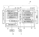
- the electric vehicle 1 is equipped with a charger 7 for charging the traveling battery 2 and a control unit (ECU) 20 as a charge control device for controlling the charger 7.
- the charger 7 is interposed between a traveling battery 2 mounted on the electric vehicle 1 and a household power source (external power source) 40 that is a commercial power source.
- the household power supply 40 and the charger 7 are connected via a charging cable connected to the charging port 8 of the electric vehicle 1, and the household power supply 40 is connected to the charger 7.
- AC power of about 100V is input.
- the charger 7 converts the input power input from the household power supply 40 into DC power of about 350 V and boosts the power to charge power suitable for charging the traveling battery 2. By inputting this charging power to the traveling battery 2, the traveling battery 2 is charged. *
- the electric vehicle 1 is provided with a display unit 50 that displays a charging state when the traveling battery 2 is charged.
- the display unit 50 includes, for example, a meter, a monitor, and the like, and appropriately displays a charging state that changes during charging based on a signal from a charging state display unit described later. *
- the “charging state” includes at least the charging efficiency that changes during charging.
- the “charged state” includes the charging efficiency and the charging rate when the traveling battery 2 is charged. That is, the display unit 50 appropriately displays the charging rate together with the charging efficiency when the traveling battery 2 is charged.
- the control unit 20 includes a charging efficiency calculating unit 21, a charging rate calculating unit 22, a first charging control unit 23, a second charging control unit 24, and a switching unit 25. With. Furthermore, the control unit 20 includes a charge state display unit 51. *
- the charging efficiency calculation means 21 calculates the charging efficiency Ec of the traveling battery 2.
- the charging efficiency calculation unit 21 includes a charger supply power calculation unit 26, a battery supply power calculation unit 27, and a charge efficiency calculation unit 28.
- the charger supply power calculation means 26 calculates the charger input power Pc input from the household power supply 40 to the charger 7.
- the charger input power Pc is calculated from the input current Ic and the input voltage Vc input from the household power supply 40 to the charger 7, and is expressed by the following equation (1).
- Pc Ic ⁇ Vc (1)
- the battery supply power calculation means 27 calculates the power supplied from the charger 7 to the traveling battery 2, that is, the battery input power Pb input to the traveling battery 2 during charging.
- the battery input power Pb is calculated from the input current Ib and the input voltage Vb input to the battery 2 for traveling, and is expressed by the following formula (2).
- Pb Ib ⁇ Vb (2)
- the charging efficiency calculation unit 28 calculates the charging efficiency Ec of the traveling battery 2 based on the calculation results of the charger supply power calculation unit 26 and the battery supply power calculation unit 27.
- the charging efficiency Ec of the traveling battery 2 is calculated from the charger input power Pc calculated by the charger supply power calculation means 26 and the battery input power Pb calculated by the battery supply power calculation means 27. 3).
- Ec Pb / Pc (3)
- the charging rate calculation means 22 calculates the charging rate (SOC) of the traveling battery 2.
- SOC charging rate
- the traveling battery 2 is provided with a voltage sensor and a current sensor (not shown), and the charging rate calculation means 22 determines the charging rate of the traveling battery 2 based on the detection results detected by these sensors. Calculate. *
- the first charging control unit 23 controls the charging of the traveling battery 2 based on the charging efficiency Ec of the traveling battery 2 calculated by the charging efficiency calculating means 21.
- the first charge control unit 23 includes a first determination unit 29 and a first charge control unit 30.
- the first determination unit 29 determines whether or not the charging efficiency Ec of the traveling battery 2 calculated by the charging efficiency calculation unit 21 is lower than a predetermined value set in advance.
- the first charging control means 30 controls the charger 7 during charging of the traveling battery 2. At that time, the first charging control means 30 appropriately controls the charger 7 according to the determination result of the first determination means 29. Specifically, when the first determining unit 29 determines that the charging efficiency Ec is lower than a predetermined value, the first charging control unit 30 controls the charger 7 to stop charging the traveling battery 2.
- the second charging control unit 24 controls the charging of the traveling battery 2 based on the charging rate (SOC) of the traveling battery 2.
- the second charge control unit 24 includes a second determination unit 31 and a second charge control unit 32.
- the second determination unit 31 determines whether or not the charging rate (SOC) of the traveling battery 2 calculated by the charging rate calculation unit 22 has reached a predetermined value.
- the second determination means 31 determines whether or not the charging rate of the traveling battery 2 has reached 100%, that is, whether or not the traveling battery 2 has been fully charged. *
- the second charge control means 32 controls the charger 7 when the traveling battery 2 is charged. At this time, the second charge control means 32 appropriately controls the charger 7 according to the determination result of the second determination means 31. Specifically, when the second determination unit 31 determines that the charging rate of the traveling battery 2 has reached a predetermined value, the second charging control unit 32 controls the charger 7 to control the traveling battery 2. Stop charging. *
- the switching unit 25 switches between the first charging mode in which charging is controlled by the first charging control unit 23 and the second charging mode in which charging is controlled by the second charging control unit 24. Switch according to user request.
- the electric vehicle 1 is provided with a changeover switch 9 for a user to perform a switching operation between the first charging mode (ECO charging mode) and the second charging mode (normal charging mode).
- the switching means 25 switches suitably between 1st charge mode and 2nd charge mode according to operation (ON / OFF) of the changeover switch 9 by a user. That is, the charging of the traveling battery 2 is controlled by either the first charge control unit 23 or the second charge control unit 24 in response to a request from the user of the electric vehicle 1.
- the charging state display means 51 displays the charging efficiency Ec and the charging rate (SOC) of the traveling battery 2 on the display unit 50. That is, the charging state display unit 51 transmits a signal corresponding to the calculation results of the charging efficiency calculation unit 21 and the charging rate calculation unit 22, and displays the charging efficiency Ec and the charging rate (SOC) of the traveling battery 2 on the display unit 50. Display. Although the display unit 50 will be described in detail later, the user of the electric vehicle 1 can easily visually recognize the state of charge of the traveling battery 2 from the display on the display unit 50. *
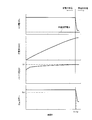
- charging control of the traveling battery 2 will be briefly described with reference to changes in various parameters.
- a constant input power is supplied to the charger 7 to charge the traveling battery 2 with a constant input power.
- Charging is performed.
- the constant input power supplied to the charger 7 is supplied to the traveling battery 2 and the DC / DC converter, but the power consumed by the DC / DC converter or the like is substantially constant.
- the power supplied to is also constant.
- the charging rate (SOC) increases and the voltage V of the traveling battery 2 gradually increases.
- the constant power charging is terminated, and thereafter, “constant voltage charging” is performed.
- the voltage V of the traveling battery 2 is controlled to be kept constant. That is, during this time, the power supplied to the charger 7 is gradually reduced, the current value of the traveling battery 2 is gradually decreased, and accordingly, the power supplied to the traveling battery 2 is also decreased.
- the power consumed by the DC / DC converter or the like is constant, the contribution ratio of the power consumed by the DC / DC converter or the like out of the power supplied from the charger 7 increases, and the value of the charging efficiency Becomes smaller.
- the charging efficiency Ec When the constant voltage charging is performed and the input power of the traveling battery 2 decreases, the charging efficiency Ec also decreases accordingly.
- the charging efficiency Ec decreases, a longer charging time is required than when the charging efficiency Ec is high even if the same amount of power is to be charged.
- a part of the electric power of the traveling battery 2 is always consumed by various auxiliary machines mounted on the electric vehicle 1. Therefore, the ratio of the power consumption to the input power to the traveling battery 2 is higher during constant voltage charging than during constant power charging, and as a result, the charging efficiency Ec during constant voltage charging is lower than during constant power charging. turn into.
- the charging efficiency Ec decreases for the same reason. *
- the charging in the state where the charging efficiency Ec as described above is lowered is stopped according to the user's request, and the charging which attaches importance to the economy is made possible.
- the first charging mode (ECO charging mode) that emphasizes economic efficiency
- the second charging mode (normal charging mode) that emphasizes cruising distance
- the first determination unit 29 appropriately determines whether or not the charging efficiency Ec is smaller than the predetermined value Ec1 (see FIG. 3), and the charging efficiency Ec is smaller than the predetermined value Ec1.
- time T2 time T2
- the first charging control means 30 controls the charger 7 to stop the charging of the traveling battery 2.
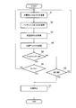
- the charging rate (SOC) and the charging efficiency Ec of the traveling battery 2 are appropriately calculated.
- the charging efficiency Ec is appropriately calculated by the charging efficiency calculator 21 in steps S1 to S3.
- the charger input power Pc input from the household power supply 40 to the charger 7 is calculated by the charger supply power calculation means 26 in step S1.
- the battery input power Pb input to the traveling battery 2 is calculated by the battery supply power calculation means 27.
- the charging efficiency calculation means 28 calculates the charging efficiency Ec of the traveling battery 2 from the charger input power Pc and the battery input power Pb.
- the charging rate calculation means 22 calculates the charging rate (SOC). *
- step S5 the switching means 25 determines whether the changeover switch (ECO switch) 9 is ON / OFF.
- step S5 Yes
- step S6 it is determined by the first determination means 29 whether or not the charging efficiency Ec of the traveling battery 2 is lower than a predetermined value Ec1.
- step S6 it is determined by the first determination means 29 that the charging efficiency Ec is lower than the predetermined value Ec1 (step S6: Yes)
- step S7 the charger 7 is controlled by the first charge control means 30 and the traveling battery 2 Charging is stopped (step S7), and a series of charging control ends.
- step S6 determines whether the charging efficiency Ec is determined to be greater than or equal to the predetermined value Ec1 by the first determination means 29 in step S6 (step S6: No).
- the predetermined value Ec1 is not particularly limited as long as it is appropriately determined in consideration of characteristics of the traveling battery 2 and the like. *
- the traveling battery 2 can be charged up to full charge, and depending on the user's request, charging is performed only during a period in which the charging efficiency Ec is high, thereby improving economy. You can also Then, by switching between the first charging mode and the second charging mode according to the user's request, it is possible to perform optimum charging according to various situations.
- the present invention can be used not only for electric vehicles but also for other electric vehicles such as plug-in hybrid vehicles. *
- the first charging control unit 23 is based on the charging rate Ec of the traveling battery 2 calculated by the charging rate calculating unit 22 together with the charging efficiency Ec of the traveling battery 2 calculated by the charging efficiency calculating unit 21.
- the charging of the traveling battery 2 may be controlled.
- the first determination means 29 determines whether or not the charging efficiency Ec is lower than a predetermined value Ec1, and determines whether or not the charging rate (SOC) is a predetermined value, for example, 90% or more. To do.
- the first charging control unit 30 controls the charger 7. Then, the charging of the traveling battery 2 is stopped.
- the electric vehicle 1 is provided with the display unit 50 as described above, and the charging efficiency Ec and the charging rate (SOC) are displayed on the display unit 50 while the traveling battery 2 is being charged. Yes. That is, the charging state display unit 51 transmits a signal corresponding to the charging efficiency Ec calculated by the charging efficiency calculation unit 21 and the charging rate (SOC) calculated by the charging rate calculation unit 22 to the display unit 50. The display of the charging efficiency Ec and the charging rate (SOC) on the display unit 50 is appropriately changed.
- a plurality of rectangular segments 52 (10 in the present embodiment) are arranged on the display unit 50 in the vertical direction (vertical direction in the figure).
- Each segment 52 is configured to be able to light independently, and the lighting range of the segment 52 changes according to the charging rate (SOC) and the charging efficiency Ec of the traveling battery 2.
- the charging rate (SOC) is represented by the number of segments 52 that are lit, and the height of the charging efficiency Ec is represented by the length of each segment in the horizontal direction (left-right direction in the figure). . *
- FIG. 5A shows an example in which the charging rate (SOC) of the traveling battery 2 is 30% to 40% and constant power charging is performed.
- SOC charging rate
- FIG. 5B shows an example in which the charging rate (SOC) of the traveling battery 2 is increased to 80% to 90% and constant voltage charging is performed. This represents a state in which the number of lighting of the segment 52 is increased from 4 to 9 with the increase.
- SOC charging rate
- constant voltage charging is performed when the charging rate of the traveling battery 2 increases to some extent, and the charging efficiency Ec gradually decreases during constant voltage charging (see FIG. 3). For this reason, the lighting region of each segment 52 at the time of constant voltage charging is smaller than that at the time of constant power charging. That is, as the charging efficiency Ec decreases, the length of each segment 52 in the lateral direction is shortened.
- the user of the electric vehicle 1 can display the charging state including at least the charging efficiency Ec on the display unit 50 based on the signal transmitted from the charging state display unit 51.
- the change in the state of charge during charging can be easily recognized visually.
- charging of the traveling battery 2 is basically automatically stopped at a predetermined timing in each charging mode.
- the charging efficiency Ec and the like can be easily visually confirmed,
- the user of the automobile 1 can also stop charging at a desired timing when the charging efficiency Ec decreases. *
- the charging efficiency Ec is represented by the length of the segment 52, but of course, the display method of the charging efficiency Ec is not limited to this. Absent.
- the change in the charging efficiency Ec during charging may be represented by the color of the segment 52.
- the charging rate (SOC) and the charging efficiency Ec are represented by one segment 52A that is long in the vertical direction. That is, in this example, the vertical lighting range of the segment 52A is expanded as the charging rate is increased. Further, the color of the lighting range of the segment 52A changes with a decrease in the charging efficiency Ec.
- the segment 52A is lit in green, and gradually changes to orange as the charging efficiency Ec decreases.
- the change in the charging efficiency Ec is represented by the color of the segment 52A, the user can easily recognize the change in the charging efficiency Ec visually.
- the color to be changed by the charging efficiency Ec is not particularly limited, and for example, the change in the charging efficiency Ec may be represented by color shading.
- the charging efficiency Ec and the charging rate (SOC) are displayed in combination.
- the charging efficiency Ec and the charging rate (SOC) may be displayed separately.
Landscapes
- Engineering & Computer Science (AREA)
- Power Engineering (AREA)
- Mechanical Engineering (AREA)
- Transportation (AREA)
- Sustainable Energy (AREA)
- Life Sciences & Earth Sciences (AREA)
- Sustainable Development (AREA)
- Manufacturing & Machinery (AREA)
- Chemical & Material Sciences (AREA)
- Chemical Kinetics & Catalysis (AREA)
- Electrochemistry (AREA)
- General Chemical & Material Sciences (AREA)
- Electric Propulsion And Braking For Vehicles (AREA)
- Charge And Discharge Circuits For Batteries Or The Like (AREA)
- Secondary Cells (AREA)
Abstract
Description
Pc=Ic×Vc (1)
Pb=Ib×Vb (2)
Ec=Pb/Pc (3)
2 走行用バッテリ
3 インバータ
4 走行用モータ
5 DC/DCコンバータ
6 補機バッテリ
7 充電器
8 充電口
9 切り替えスイッチ
20 制御部(充電制御装置)
21 充電効率演算手段
22 充電率演算手段
23 第1の充電制御部
24 第2の充電制御部
25 切り替え手段
26 充電器供給電力演算手段
27 バッテリ供給電力演算手段
28 充電効率計算手段
29 第1の判定手段
30 第1の充電制御手段
31 第2の判定手段
32 第2の充電制御手段
40 家庭用電源(商用電源)
50 表示部
51 充電状態表示手段
52 セグメント
Claims (9)
- 外部電源から充電器を介して供給される電力によって車両に搭載された走行用バッテリの充電を行う電動車両の充電制御装置であって、
前記走行用バッテリの充電効率を演算する充電効率演算手段と、
前記走行用バッテリの充電率を演算する充電率演算手段と、
前記充電効率に基づいて前記充電器を制御して前記走行用バッテリを充電する第1の充電モードと、前記充電率に基づいて前記充電器を制御して前記走行用バッテリを充電する第2の充電モードとを、前記車両のユーザの要求に応じて切り替える切り替え手段と、
を備えたことを特徴とする電動車両の充電制御装置。 - 前記充電効率演算手段によって演算された前記走行用バッテリの充電効率が所定値よりも低いか否かを判定する第1の判定手段を更に備え、
前記切り替え手段により前記第1の充電モードが選択され、かつ、前記第1の判定手段によって前記充電効率が所定値よりも低いと判定された際に、前記充電器を制御して前記走行用バッテリの充電を停止させることを特徴とする請求項1に記載の電動車両の充電制御装置。 - 前記外部電源から前記充電器へ供給される電力を演算する充電器供給電力演算手段と、
前記充電器から前記走行用バッテリへ供給される電力を演算するバッテリ供給電力演算手段と、を更に備え、
前記充電効率演算手段は、前記充電器供給電力演算手段及び前記バッテリ供給電力演算手段の演算結果に基づいて充電効率を演算することを特徴とする請求項1又は2に記載の電動車両の充電制御装置。 - 前記充電効率演算手段は、前記充電器から前記走行用バッテリへ供給される電力を前記外部電源から前記充電器へ供給される電力で除した値を前記充電効率と定めることを特徴とする請求項3に記載の電動車両の充電制御装置。
- 前記充電率演算手段によって演算された前記走行用バッテリの充電率が所定値に達したか否かを判定する第2の判定手段を更に備え、
前記切り替え手段により前記第2の充電モードが選択され、かつ、前記第2の判定手段によって前記充電率が所定値に達したと判定された際に、前記充電器を制御して前記走行用バッテリの充電を停止させることを特徴とする請求項1~4の何れか一項に記載の電動車両の充電制御装置。 - 前記車両に備えられた表示部に前記走行用バッテリの充電状態を表示させる充電状態表示手段を、さらに備え、
該充電状態表示手段が、前記充電状態として少なくとも前記充電効率を前記表示部に表示させることを特徴とする請求項1~5の何れか一項に記載の電動車両の充電制御装置。 - 前記充電状態表示手段は、前記充電状態として前記充電効率と共に前記充電率を前記表示部に表示させることを特徴とする請求項6に記載の電動車両の充電制御装置。
- 前記充電状態表示手段は、前記充電効率の高さをセグメントの高さとして前記表示部に表示させることを特徴とする請求項6又は7に記載の電動車両の充電制御装置。
- 前記充電状態表示手段は、前記充電効率の変化をセグメントの色の変化として前記表示部に表示させることを特徴とする請求項6又は7に記載の電動車両の充電表示装置。
Priority Applications (4)
| Application Number | Priority Date | Filing Date | Title |
|---|---|---|---|
| US13/885,308 US8880264B2 (en) | 2010-11-15 | 2011-11-02 | Charging control apparatus for electric vehicle |
| JP2012544174A JP5776909B2 (ja) | 2010-11-15 | 2011-11-02 | 電動車両の充電制御装置 |
| EP11841422.6A EP2642631B1 (en) | 2010-11-15 | 2011-11-02 | Charging control device for electric vehicle |
| CN201180065055.5A CN103314503B (zh) | 2010-11-15 | 2011-11-02 | 电动车辆的充电控制装置 |
Applications Claiming Priority (2)
| Application Number | Priority Date | Filing Date | Title |
|---|---|---|---|
| JP2010-255351 | 2010-11-15 | ||
| JP2010255351 | 2010-11-15 |
Publications (1)
| Publication Number | Publication Date |
|---|---|
| WO2012066934A1 true WO2012066934A1 (ja) | 2012-05-24 |
Family
ID=46083871
Family Applications (1)
| Application Number | Title | Priority Date | Filing Date |
|---|---|---|---|
| PCT/JP2011/075278 Ceased WO2012066934A1 (ja) | 2010-11-15 | 2011-11-02 | 電動車両の充電制御装置 |
Country Status (5)
| Country | Link |
|---|---|
| US (1) | US8880264B2 (ja) |
| EP (1) | EP2642631B1 (ja) |
| JP (1) | JP5776909B2 (ja) |
| CN (1) | CN103314503B (ja) |
| WO (1) | WO2012066934A1 (ja) |
Cited By (1)
| Publication number | Priority date | Publication date | Assignee | Title |
|---|---|---|---|---|
| JP2014050291A (ja) * | 2012-09-04 | 2014-03-17 | Nissan Motor Co Ltd | 電池状態表示装置 |
Families Citing this family (13)
| Publication number | Priority date | Publication date | Assignee | Title |
|---|---|---|---|---|
| KR101428163B1 (ko) * | 2012-05-25 | 2014-08-07 | 엘지이노텍 주식회사 | 단말기 상태를 시각적으로 나타내는 장치 및 방법 |
| KR101509965B1 (ko) * | 2013-11-11 | 2015-04-07 | 현대자동차주식회사 | 배터리 충전 장치 및 방법 |
| KR101558705B1 (ko) * | 2013-12-26 | 2015-10-07 | 현대자동차주식회사 | 배터리 충전 제어 장치 및 방법 |
| US10552923B2 (en) | 2014-05-08 | 2020-02-04 | Honda Motor Co., Ltd. | Electric vehicle charging control system |
| US10019155B2 (en) | 2014-06-30 | 2018-07-10 | Honda Motor Co., Ltd. | Touch control panel for vehicle control system |
| US20170232855A1 (en) * | 2016-02-11 | 2017-08-17 | GM Global Technology Operations LLC | High voltage battery charger and methods of operation |
| DE102016205374A1 (de) * | 2016-03-31 | 2017-10-05 | Siemens Aktiengesellschaft | Verfahren und Vorrichtung zum Laden einer Batterie |
| DE102017204247A1 (de) * | 2017-03-14 | 2018-09-20 | Robert Bosch Gmbh | Verfahren zum Betrieb eines Ladegeräts |
| KR102466380B1 (ko) | 2017-06-07 | 2022-11-14 | 현대자동차주식회사 | 차량용 직류 변환기 제어방법 및 시스템 |
| JP7035571B2 (ja) * | 2018-01-31 | 2022-03-15 | トヨタ自動車株式会社 | 電動車両 |
| CN112448054B (zh) * | 2019-08-30 | 2023-02-17 | 北京小米移动软件有限公司 | 移动终端的充电方法、装置、终端及存储介质 |
| WO2021158724A1 (en) * | 2020-02-07 | 2021-08-12 | Enersys Delaware Inc. | Methods, systems, and devices for charging advanced sealed lead acid batteries |
| CN115616326A (zh) * | 2022-11-08 | 2023-01-17 | 奇瑞新能源汽车股份有限公司 | 电动汽车的充电效率测试方法、装置、设备及介质 |
Citations (4)
| Publication number | Priority date | Publication date | Assignee | Title |
|---|---|---|---|---|
| JPH0773903A (ja) * | 1993-09-03 | 1995-03-17 | Honda Motor Co Ltd | 二次電池の充電制御方法 |
| JP2000023383A (ja) * | 1998-06-29 | 2000-01-21 | Honda Motor Co Ltd | バッテリ充電装置 |
| JP2008083022A (ja) * | 2006-08-30 | 2008-04-10 | Toyota Motor Corp | 蓄電装置の劣化評価システム、車両、蓄電装置の劣化評価方法およびその劣化評価方法をコンピュータに実行させるためのプログラムを記録したコンピュータ読取可能な記録媒体 |
| JP2009284685A (ja) | 2008-05-23 | 2009-12-03 | Lecip Corp | 充電装置 |
Family Cites Families (33)
| Publication number | Priority date | Publication date | Assignee | Title |
|---|---|---|---|---|
| US5545969A (en) * | 1992-12-02 | 1996-08-13 | Matsushita Electric Industrial Co., Ltd. | Battery residual capacity displaying system with discharged electrical quantity computation section |
| DE4344368C1 (de) * | 1993-12-24 | 1995-05-11 | Daimler Benz Ag | Ladeinformationssystem für ein Elektro- oder Hybridfahrzeug |
| JPH07198808A (ja) * | 1993-12-28 | 1995-08-01 | Honda Motor Co Ltd | 電気自動車用バッテリの残容量表示装置 |
| US5939855A (en) * | 1994-09-06 | 1999-08-17 | Cruising Equipment, Inc. | Power conversion equipment monitor/controller method and apparatus |
| JPH08106921A (ja) * | 1994-10-03 | 1996-04-23 | Nissan Motor Co Ltd | 自動車用バッテリの充電方法及び装置 |
| JP3246226B2 (ja) * | 1994-10-03 | 2002-01-15 | 日産自動車株式会社 | 自動車用バッテリの充電装置 |
| JP3509382B2 (ja) | 1995-04-27 | 2004-03-22 | 日産自動車株式会社 | 充電制御システム |
| JP3638369B2 (ja) * | 1996-03-26 | 2005-04-13 | 東芝電池株式会社 | 二次電池の充電制御方法 |
| JP3415740B2 (ja) * | 1997-04-14 | 2003-06-09 | 本田技研工業株式会社 | バッテリ充電装置 |
| JPH1198697A (ja) | 1997-09-25 | 1999-04-09 | Nissan Motor Co Ltd | 電気車用二次電池の充電制御方法および充電制御装置 |
| JPH11341695A (ja) | 1998-05-27 | 1999-12-10 | Toshiba Battery Co Ltd | 二次電池の充電制御装置 |
| US6215281B1 (en) * | 2000-03-16 | 2001-04-10 | General Motors Corporation | Method and apparatus for reducing battery charge time and energy consumption, as in a nickel metal hydride battery pack |
| JP2001309569A (ja) | 2000-04-26 | 2001-11-02 | Nippon Telegr & Teleph Corp <Ntt> | 複数キャパシタの充放電方法及び装置 |
| US6320354B1 (en) * | 2000-07-21 | 2001-11-20 | Motorola, Inc. | Method and apparatus for battery charging |
| US6353304B1 (en) * | 2001-01-19 | 2002-03-05 | Sandia Corporation | Optimal management of batteries in electric systems |
| JP3720290B2 (ja) * | 2001-10-04 | 2005-11-24 | 矢崎総業株式会社 | バッテリの充電効率検出方法及びその装置、バッテリの充電電気量検出方法及びその装置 |
| JP2004301782A (ja) * | 2003-03-31 | 2004-10-28 | Yazaki Corp | 満充電状態検出装置及びその方法、充電状態検出装置及びその方法、劣化度検出装置及びその方法 |
| CN101512364A (zh) * | 2006-08-30 | 2009-08-19 | 丰田自动车株式会社 | 蓄电装置的劣化评价系统、车辆、蓄电装置的劣化评价方法以及储存有用于使计算机执行该劣化评价方法的程序的计算机能够读取的存储介质 |
| JP2008067426A (ja) * | 2006-09-04 | 2008-03-21 | Yamaha Motor Electronics Co Ltd | 車両用充電制御方法 |
| JP2008295170A (ja) | 2007-05-23 | 2008-12-04 | Canon Inc | 充電装置及びその制御方法 |
| US7782021B2 (en) * | 2007-07-18 | 2010-08-24 | Tesla Motors, Inc. | Battery charging based on cost and life |
| JP4769779B2 (ja) * | 2007-09-21 | 2011-09-07 | 富士重工業株式会社 | 電気自動車の充電状態表示装置 |
| JP2009100569A (ja) * | 2007-10-17 | 2009-05-07 | Toyota Motor Corp | 車両および充電ケーブル |
| KR101432590B1 (ko) | 2007-12-12 | 2014-08-21 | 엘지전자 주식회사 | 무선 충전용 메뉴 제공 기능을 갖는 이동 단말기 및 그충전방법 |
| JP2009189088A (ja) | 2008-02-04 | 2009-08-20 | Fujifilm Corp | 無接点充電装置 |
| JP2010011523A (ja) | 2008-06-24 | 2010-01-14 | Toyota Motor Corp | 充電状態表示装置 |
| JP5228825B2 (ja) | 2008-11-17 | 2013-07-03 | トヨタ自動車株式会社 | 車両の電源システムおよび車両 |
| JP5024558B2 (ja) * | 2008-11-21 | 2012-09-12 | 本田技研工業株式会社 | 充電制御装置 |
| CN101764434B (zh) * | 2008-12-22 | 2014-05-14 | 爱信艾达株式会社 | 受电引导装置 |
| JP5334620B2 (ja) | 2009-02-20 | 2013-11-06 | オムロンオートモーティブエレクトロニクス株式会社 | 充電装置および充電方法 |
| JP2010200530A (ja) | 2009-02-26 | 2010-09-09 | Omron Corp | 充電制御装置および方法、充電装置および方法、並びに、プログラム |
| JP2010206871A (ja) | 2009-02-27 | 2010-09-16 | Panasonic Electric Works Co Ltd | 非接触被充電装置ならびにそれを用いる非接触充電システムおよび電気機器 |
| FR2950742B1 (fr) * | 2009-09-29 | 2011-10-07 | Commissariat Energie Atomique | Procede de charge et procede de determination d'un critere de fin de charge d'une batterie a base de nickel |
-
2011
- 2011-11-02 WO PCT/JP2011/075278 patent/WO2012066934A1/ja not_active Ceased
- 2011-11-02 US US13/885,308 patent/US8880264B2/en active Active
- 2011-11-02 JP JP2012544174A patent/JP5776909B2/ja not_active Expired - Fee Related
- 2011-11-02 CN CN201180065055.5A patent/CN103314503B/zh not_active Expired - Fee Related
- 2011-11-02 EP EP11841422.6A patent/EP2642631B1/en not_active Not-in-force
Patent Citations (4)
| Publication number | Priority date | Publication date | Assignee | Title |
|---|---|---|---|---|
| JPH0773903A (ja) * | 1993-09-03 | 1995-03-17 | Honda Motor Co Ltd | 二次電池の充電制御方法 |
| JP2000023383A (ja) * | 1998-06-29 | 2000-01-21 | Honda Motor Co Ltd | バッテリ充電装置 |
| JP2008083022A (ja) * | 2006-08-30 | 2008-04-10 | Toyota Motor Corp | 蓄電装置の劣化評価システム、車両、蓄電装置の劣化評価方法およびその劣化評価方法をコンピュータに実行させるためのプログラムを記録したコンピュータ読取可能な記録媒体 |
| JP2009284685A (ja) | 2008-05-23 | 2009-12-03 | Lecip Corp | 充電装置 |
Non-Patent Citations (1)
| Title |
|---|
| See also references of EP2642631A4 |
Cited By (1)
| Publication number | Priority date | Publication date | Assignee | Title |
|---|---|---|---|---|
| JP2014050291A (ja) * | 2012-09-04 | 2014-03-17 | Nissan Motor Co Ltd | 電池状態表示装置 |
Also Published As
| Publication number | Publication date |
|---|---|
| CN103314503B (zh) | 2015-10-21 |
| EP2642631A1 (en) | 2013-09-25 |
| CN103314503A (zh) | 2013-09-18 |
| US20130231818A1 (en) | 2013-09-05 |
| JP5776909B2 (ja) | 2015-09-09 |
| EP2642631A4 (en) | 2018-02-07 |
| US8880264B2 (en) | 2014-11-04 |
| JPWO2012066934A1 (ja) | 2014-05-12 |
| EP2642631B1 (en) | 2019-05-08 |
Similar Documents
| Publication | Publication Date | Title |
|---|---|---|
| JP5776909B2 (ja) | 電動車両の充電制御装置 | |
| JP6119966B2 (ja) | ハイブリッド車の走行モード切換制御装置 | |
| US8655532B2 (en) | System and method for operating a hybrid vehicle | |
| US9315105B2 (en) | Electrically-driven vehicle and method for controlling the same | |
| US8718849B2 (en) | Hybrid vehicle and control method therefor | |
| US8755964B2 (en) | Hybrid vehicle | |
| US9758050B2 (en) | Display system for electrically powered vehicle and electrically powered vehicle having the same | |
| JP5293773B2 (ja) | 蓄電装置用の充電装置およびそれを搭載する車両、ならびに充電装置の制御方法 | |
| KR101761539B1 (ko) | 하이브리드 차량 | |
| JP2010028881A (ja) | 制御装置、及び制御方法 | |
| US9701186B2 (en) | Vehicle | |
| JP5896019B2 (ja) | 車両 | |
| CN102666187A (zh) | 电力控制装置和电力控制方法 | |
| KR20130120229A (ko) | 전기 자동차의 충전 방법 | |
| JP2020072581A (ja) | 移動可能距離算出装置 | |
| JP6187302B2 (ja) | 車両の制御装置 | |
| JP2013251961A (ja) | 充電装置 | |
| JP5633691B2 (ja) | 電動車両の充電表示装置 | |
| CN102405416B (zh) | 充电控制系统 | |
| JP6222891B2 (ja) | ハイブリッド車両の制御装置 | |
| JP2013133061A (ja) | ハイブリッド車 | |
| JP2013158082A (ja) | 車両および車両の制御方法 | |
| JP6270010B2 (ja) | 車両の電力制御装置 | |
| WO2013154093A1 (ja) | ハイブリッド車両の制御装置、ハイブリッド車両の管理システム、及びハイブリッド車両の管理方法 | |
| JP2017121148A (ja) | 車両用バッテリの充電装置 |
Legal Events
| Date | Code | Title | Description |
|---|---|---|---|
| 121 | Ep: the epo has been informed by wipo that ep was designated in this application |
Ref document number: 11841422 Country of ref document: EP Kind code of ref document: A1 |
|
| ENP | Entry into the national phase |
Ref document number: 2012544174 Country of ref document: JP Kind code of ref document: A |
|
| WWE | Wipo information: entry into national phase |
Ref document number: 13885308 Country of ref document: US |
|
| NENP | Non-entry into the national phase |
Ref country code: DE |
|
| WWE | Wipo information: entry into national phase |
Ref document number: 2011841422 Country of ref document: EP |