WO2012067238A1 - キャンセルカム構造及び回転コネクタ装置 - Google Patents
キャンセルカム構造及び回転コネクタ装置 Download PDFInfo
- Publication number
- WO2012067238A1 WO2012067238A1 PCT/JP2011/076696 JP2011076696W WO2012067238A1 WO 2012067238 A1 WO2012067238 A1 WO 2012067238A1 JP 2011076696 W JP2011076696 W JP 2011076696W WO 2012067238 A1 WO2012067238 A1 WO 2012067238A1
- Authority
- WO
- WIPO (PCT)
- Prior art keywords
- cam
- wall
- cancel
- outer peripheral
- ratchet
- Prior art date
- Legal status (The legal status is an assumption and is not a legal conclusion. Google has not performed a legal analysis and makes no representation as to the accuracy of the status listed.)
- Ceased
Links
Images




Classifications
-
- B—PERFORMING OPERATIONS; TRANSPORTING
- B60—VEHICLES IN GENERAL
- B60Q—ARRANGEMENT OF SIGNALLING OR LIGHTING DEVICES, THE MOUNTING OR SUPPORTING THEREOF OR CIRCUITS THEREFOR, FOR VEHICLES IN GENERAL
- B60Q1/00—Arrangement of optical signalling or lighting devices, the mounting or supporting thereof or circuits therefor
- B60Q1/26—Arrangement of optical signalling or lighting devices, the mounting or supporting thereof or circuits therefor the devices being primarily intended to indicate the vehicle, or parts thereof, or to give signals, to other traffic
- B60Q1/34—Arrangement of optical signalling or lighting devices, the mounting or supporting thereof or circuits therefor the devices being primarily intended to indicate the vehicle, or parts thereof, or to give signals, to other traffic for indicating change of drive direction
- B60Q1/40—Arrangement of optical signalling or lighting devices, the mounting or supporting thereof or circuits therefor the devices being primarily intended to indicate the vehicle, or parts thereof, or to give signals, to other traffic for indicating change of drive direction having mechanical, electric or electronic automatic return to inoperative position
- B60Q1/42—Arrangement of optical signalling or lighting devices, the mounting or supporting thereof or circuits therefor the devices being primarily intended to indicate the vehicle, or parts thereof, or to give signals, to other traffic for indicating change of drive direction having mechanical, electric or electronic automatic return to inoperative position having mechanical automatic return to inoperative position due to steering-wheel position, e.g. with roller wheel control
- B60Q1/425—Arrangement of optical signalling or lighting devices, the mounting or supporting thereof or circuits therefor the devices being primarily intended to indicate the vehicle, or parts thereof, or to give signals, to other traffic for indicating change of drive direction having mechanical, electric or electronic automatic return to inoperative position having mechanical automatic return to inoperative position due to steering-wheel position, e.g. with roller wheel control using a latching element for resetting a switching element
Definitions
- the present invention relates to a cancel cam structure and a rotary connector device in which a turn lever for instructing a turning direction of an automobile is rotated and returned from a left turn instruction rotation position or a right turn instruction rotation position to a neutral position by rotation of a steering wheel.
- the driver turns the steering wheel in the opposite direction to the turning operation and returns it to the neutral position.
- the turn lever can automatically return to the neutral position in accordance with the turning operation of the driver returning the steering wheel to the neutral position.
- a cancel mechanism 1 ′ including the turn lever 40, the cancel cam structure 10 ′, the bracket 30, and the ratchet 20 is used. Realized.
- the cancel cam structure 10 ' is configured to rotate in the same manner as the steering wheel (not shown) by a turning operation of the steering wheel (not shown).
- the bracket 30 is disposed between the turn lever 40 and the cancel cam structure 10 ′, and can be rotated by the rotation of the cancel cam structure 10 ′ and the turn lever 40.
- the ratchet 20 transmits the turning force of the cancel cam structure 10 ′ when the steering wheel is rotated to return to the neutral position N to the bracket 30 to rotate the bracket 30 and the turn lever 40 to the neutral position N. This is a configuration for returning.
- the ratchet 20 is urged toward the cancel cam structure 10 ′ by the ratchet spring 22 that constitutes the urging means.
- the opposite cancel cam side end 25 of the ratchet 20 opposite to the cancel cam structure 10 ′ is located between the two engaging portions 32 and 33 for cancellation provided on the bracket 30. Is located.
- the bracket 30 is held at the neutral position N by moderation means (not shown).
- the anti-cancellation cam side end portion 25 of the ratchet 20 is in a state of being close to one of the two engaging portions 32 and 33.
- the turn signal switch is activated and the turn signal lamp for left turn blinks.
- the ratchet 20 is rotated in a direction away from the engaging portion 32 in which the anti-cancellation cam side end portion 25 is close, so that the bracket 30 and the turn lever 40 are held at the left turn instruction position L. Will remain.
- the turn signal switch for the left turn continues to flash while the turn signal switch remains unchanged.
- the ratchet 20 rotates in the direction in which the anti-cancellation cam side end portion 25 engages with the engaging portion 32 that is close to the ratchet 20, so that the bracket 30 and the turn lever 40 are turned to the left via the engaging portion 32. It is turned from the indicated position L in the neutral position N direction and returned to the neutral position N. Accordingly, the turn signal switch (not shown) is turned off, and the left turn signal lamp (not shown) is turned off.
- the cam portion 12 ′ of the conventional cancel cam structure 10 ′ is made of plastic, for example, as shown in FIG. 9, a cylindrical outer cam wall 13 a ′ with which the cancel cam side end portion 24 of the ratchet 20 contacts.
- a cylindrical inner wall 13b ' having the same central axis position as that of the cylindrical shaft and having a small diameter, and two connecting cam walls 13c' and 13d 'stretched in the radial direction are formed in a cylindrical shape.
- the interior was a cavity (go space S ′).
- the cam portion 12 ′ of the cancel cam structure 10 ′ In the configuration of the cam portion 12 ′ of the cancel cam structure 10 ′, when the turn lever is turned to the left turn instruction position L (or the right turn instruction position R), the cam portion 12 ′ has an end on the cancel cam side. When the portion 24 comes into contact, there is a problem that the contact sound (sounding sound) between the cam portion 12 ′ of the cancel cam structure 10 ′ and the cancel cam side end portion 24 of the ratchet 20 is loud, which is uncomfortable for the driver.
- an object of the present invention is to provide a cancel cam structure and a rotary connector device that can suppress a contact sound (sounding sound) between the cancel cam structure and the ratchet.
- the present invention has a cancel cam structure that has a cam portion that allows the ratchet to contact, and that is disposed on a radially outer side with respect to the axial direction of the steering shaft and that rotates as the steering wheel connected to the steering shaft rotates.
- the cam portion includes an outer peripheral cam wall that allows the ratchet to slide, an inner wall that is radially inside of the outer peripheral cam wall, and a connecting cam that connects both ends of the outer peripheral cam wall and the inner wall.
- a surrounding space that is formed by a wall and is formed in a direction parallel to the axial direction, and surrounded by the outer circumferential cam wall, the inner side wall, and the coupling cam wall.
- at least one of the outer peripheral cam wall, the inner side wall, and the connecting cam wall is provided with a protruding portion that protrudes toward the surrounding space.
- the wall surface of the inner wall includes wall surfaces of various shapes such as a peripheral surface and a flat surface.
- a contact sound (striking sound) between the cancel cam structure and the ratchet can be reduced.
- the rigidity of the cam portion is increased.
- the range and amplitude of vibration of the cam portion due to the ratchet coming into contact with the cam portion can be reduced. Therefore, the contact sound (sounding sound) between the cancel cam structure and the ratchet can be suppressed to a low level, and the ride quality of the driver can be improved.
- the mass of the outer peripheral cam wall increases, and the vibration of the outer peripheral wall is delayed due to inertia.
- the contact sound with the ratchet can be lowered.
- the shape of an arbitrary cross section perpendicular to the axial direction of the outer peripheral cam wall is an arc shape having a constant diameter centering on the intersection of the axial center of the steering shaft and the arbitrary cross section.
- the inner wall is configured to extend uniformly in the axial direction
- the shape of an arbitrary cross section perpendicular to the axial direction is centered on the intersection of the axial center and the arbitrary cross section
- the outer peripheral cam wall It is a circular arc shape having a constant diameter smaller than the diameter, and is configured to extend uniformly in the axial direction
- the protruding portion is a flat partition wall that divides the surrounding space upright along the axial direction. Can be configured.
- the contact sound (sounding sound) between the cancel cam and the ratchet can be further reduced.
- the protrusion is arranged so as to stand upright in the axial direction, and is constituted by the flat partition wall that divides the surrounding space, so that the cam is compared with the case where the protrusion is not the partition wall.
- the rigidity of the part can be increased. Therefore, the range and amplitude of vibration of the cam portion due to the ratchet contacting the cam portion can be further reduced, and the contact sound (sounding sound) between the cancel cam and the ratchet can be further reduced. it can.
- the cam portion since the cam portion has a uniform shape in the axial direction, plastic molding of the cam portion capable of exhibiting the above-described effects can be facilitated.
- the dividing wall can be arranged upright along the radial direction.
- the radial rigidity of the cam portion can be increased. Therefore, the vibration of the cam portion when the ratchet approaches and contacts the outer peripheral cam wall of the cam portion from the radially outer side toward the inner side can be significantly suppressed. Therefore, the contact sound (sounding sound) generated when the ratchet contacts the central axis of the cam portion can be significantly reduced.
- the circumferential length of the portion of the outer peripheral cam wall divided by dividing by the dividing wall is different from the circumferential length of the portion of the inner wall facing it, Resonance of the inner wall due to vibration of the outer peripheral cam wall is less likely to occur. Therefore, it is possible to suppress a contact sound (sounding sound) generated when the ratchet contacts the cam portion.
- a plurality of the dividing walls can be provided. According to the present invention, since the rigidity is higher than that of the cam portion having only one dividing wall, vibration of the cancel cam structure due to contact between the ratchet and the cancel cam structure can be further reduced. Accordingly, the contact sound (sounding sound) can be further reduced.
- a plurality of the dividing walls are provided at a predetermined interval, and the adjacent continuous cam wall and the dividing wall and the interval between the adjacent dividing walls are set to at least two kinds or more. Can do.
- the surrounding space partitioned by the dividing wall is composed of two or more types of spaces having different shapes, the natural frequency of the cancel cam structure can be distributed to two or more. Therefore, resonance of the cam portion of the cancel cam structure can be suppressed.
- the present invention also provides a fixed case formed of an annular fixed side ring plate and a cylindrical outer peripheral cylindrical portion extending perpendicularly from an outer peripheral edge of the fixed side ring plate, an annular rotary side ring plate, and the rotary ring plate.
- a rotating case formed by a cylindrical inner peripheral cylindrical portion extending perpendicularly from the inner peripheral edge to the fixed case side is fitted so as to be relatively rotatable in a clockwise direction and a counterclockwise direction, and a fixed side ring of the fixed case A flat which electrically connects the stationary case side and the rotating case side to the accommodating space, with the accommodating space being constituted by the plate and the outer peripheral cylindrical portion, and the rotating side ring plate and the inner peripheral cylindrical portion of the rotating case.
- the rotary connector device is provided with the cancel cam structure on a rotary connector which is wound and accommodated with a cable.
- the cancel cam structure can suppress vibration caused by the ratchet coming into contact with the cancel cam structure, so that the rotary connector device that suppresses vibration applied to the rotary connector body is configured. Can do.
- FIG. The perspective view of a rotation connector apparatus. Explanatory drawing which shows the neutral state of a cancellation mechanism. Explanatory drawing which shows the left turn instruction
- FIG. The perspective view of a cancellation cam structure. The top view of the cancellation cam structure of other embodiment. Explanatory drawing which shows the neutral state of the cancellation cam mechanism of a prior art example. Explanatory drawing which shows the left turn instruction
- FIG. 1 is a perspective view showing a rotary connector device 2 having a cancel cam structure 10 of the present embodiment.
- 2 is an explanatory view showing a neutral state of the cancel mechanism 1 viewed from the steering wheel side
- FIG. 3 is an explanatory view showing a left turn instruction state of the cancel mechanism 1 also viewed from the steering wheel side.
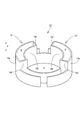
- FIG. 4 is a plan view of the cancel cam structure 10 viewed from the combination switch side (vehicle body side), and FIG. 5A is a perspective view of the cancel cam structure 10 viewed from the combination switch side (vehicle body side).
- FIG. 5B is a cross-sectional view taken along the line AA in FIG.
- the rotary connector device 2 of the present embodiment has a configuration in which a cancel cam structure 10 is provided in a rotary connector 70.
- a steering wheel (not shown) is provided below the rotary connector device 2 in FIG. 1, and the upper surface of the rotary connector device 2 in FIG. 1 is attached to a combination switch on the vehicle body side (not shown).
- a steering shaft (not shown) is inserted into the hollow portion H of the rotary connector device 2.
- the rotary connector 70 is mainly composed of a fixed case 71, a rotary case 72, and a flat cable (not shown).
- the fixed case 71 includes an annular fixed ring plate 71a and an outer peripheral cylindrical portion 71b extending vertically downward from the outer peripheral edge of the fixed ring plate 71a in the lower part of FIG. The above combination switch is fixed.
- the rotating case 72 includes an annular rotating side ring plate (not shown) and a cylindrical inner peripheral cylindrical portion 72b extending vertically from the inner peripheral edge of the rotating side ring plate upward in FIG. Moreover, it fixes to the said steering wheel with which the downward direction of FIG. 1 was equipped, and rotates with a steering wheel.
- the rotary connector device 2 is mounted on the vehicle so that the rotary case 72 is on the upper side.
- the stationary ring plate 71a and the outer peripheral cylindrical portion 71b of the fixed case 71 and the rotational ring plate and the inner peripheral cylindrical portion 72b of the rotating case 72 constitute an accommodating space for accommodating the flat cable.
- This flat cable is wound and accommodated in the accommodation space, and electrically connects the fixed case 71 side and the rotary case 72 side.
- the cancel cam structure 10 is attached to the inner peripheral cylindrical portion 72b of the rotating case 72, and is configured to rotate integrally with the steering wheel.
- the cancel mechanism 1 of the present embodiment is configured by the cancel cam structure 10, the bracket 30, the turn lever 40, and the ratchet 20 as shown in FIGS.
- the cancel cam structure 10 of the present embodiment is made of plastic and has a diameter allowing the insertion of the steering shaft, as shown in FIGS. 4 and 5, and is generally a cylindrical inner portion extending in the axial direction X of the steering shaft.
- a cylinder 11a and a cylindrical outer cylinder 11b having the same central axis as the inner cylinder 11a and a larger diameter than the inner cylinder 11a are formed into a cylindrical shape.
- it is the structure where the axial center of a steering shaft and the central axis of the inner cylinder 11a and the outer cylinder 11b correspond.
- the cancel cam structure 10 is provided with cam portions 12 projecting in the central axis direction symmetrically.
- the cam portion 12 on one side includes a cylindrical outer wall 13 and a dividing wall 14 that divides the surrounding space S surrounded by the outer wall 13.
- the outer wall 13 is formed in a cylindrical shape surrounded by the outer peripheral cam wall 13a, the inner side wall 13b, and the connecting cam walls 13c and 13d.
- the outer peripheral cam wall 13a has an arc shape in which an arbitrary cross section perpendicular to the axial direction X of the steering shaft, with which a cancel cam side end 24 of the ratchet 20 described later contacts, is centered on the central axis and has a constant diameter. And formed in a shape extending uniformly in the axial direction X.
- the inner wall 13b has an arc shape in which the shape of the arbitrary cross section is centered on the central axis and has a constant diameter smaller than the diameter of the outer cam wall 13a. It is formed in a shape that extends uniformly in X. Furthermore, the connecting cam walls 13c and 13d are formed in a flat plate shape that connects the ends of the outer peripheral cam wall 13a and the inner side wall 13b and stands upright along the axial direction X.
- the dividing wall 14 includes a first dividing wall 14a, a second dividing wall 14b, and a second dividing wall 14c.
- the dividing walls 14 (the first dividing wall 14a, the second dividing wall 14b, and the second dividing wall 14c) are all formed in a flat plate shape having the same thickness, and the axial direction X and the radial direction of the cancel cam structure 10 It is arranged so as to stand up along.
- the dividing wall 14 is provided from the upper end 12U to the lower end 12D of the cam portion 12 in the axial direction X, and connects the outer peripheral cam wall 13a and the inner side wall 13b. . Further, the dividing walls 14 are arranged at equal intervals in the circumferential direction so that the surrounding space S surrounded by the outer wall 13 is divided into four equal parts in the circumferential direction of the cancel cam structure 10.
- a body main body 51 of the cancel mechanism built-in body 50 is provided in a state of being fixed to the vehicle body side.
- the cancel mechanism built-in body 50 is composed of a lower body body 51 and a cover (not shown) attached to the upper surface of the body body 51.
- a bracket 30, a turn lever 40, and a ratchet 20 are disposed inside the body main body 51 of the cancel mechanism built-in body 50.
- the bracket 30 is provided so as to be rotatable in the directions of arrows A1 and A2 in FIG.
- a back plate 34 having two engaging portions 32, 33 for cancellation is provided on the upper surface portion of the bracket 30.
- the back plate 34 is provided so as to be movable in the directions of the arrows C1 and C2 in FIG. 2, and is normally held by the back spring 35 at the equilibrium position of the back spring 35 shown in FIG.
- the two engaging portions 32 and 33 are arranged in a C shape when viewed from the cancel cam structure 10 side.
- a guide convex portion 36 (see FIG. 3) that has a mountain shape and protrudes toward the combination switch is formed on the distal end portion side (cancellation cam structure 10 side) of the bracket 30. Further, guide concave portions 37 lower than the guide convex portion 36 are formed on both sides of the guide convex portion 36.
- a ratchet 20 is disposed on the tip end side of the upper surface of the bracket 30, and this ratchet 20 is covered from above by a cover (not shown).
- a ratchet shaft portion 21 that protrudes in the vertical direction is provided integrally with the ratchet 20 at a substantially intermediate portion in the longitudinal direction of the ratchet 20, and the ratchet 20 can swing around the ratchet shaft portion 21.
- the lower portion of the ratchet shaft portion 21 is inserted into the tip end portion side of the bracket 30, and the upper portion of the ratchet shaft portion 21 is movably inserted into a guide groove 52a formed on the inner surface of the cover.
- the guide groove 52 a extends in a direction along a line connecting the center of the bracket shaft portion 31 that is the rotation center of the bracket 30 and the rotation center of the cancel cam structure 10.
- a spring recess is formed in the lower portion of the ratchet 20, and an intermediate portion of a ratchet spring 22 made of a tension coil spring is inserted into the spring recess. Both end portions in the longitudinal direction of the ratchet spring 22 are hooked on the body main body 51, and the ratchet 20 is biased toward the cancel cam structure 10 (in the direction of arrow D in FIG. 2) by the biasing force of the ratchet spring 22. .
- the ratchet 20 is provided so as to be able to swing around the ratchet shaft portion 21 described above, and to be movable in the direction approaching and separating from the cancel cam structure 10 along the guide groove 52a.
- the cancel cam side end 24 on the cancel cam structure 10 side protrudes from the opening 51 a of the body main body 51 toward the cancel cam structure 10, and is on the side opposite to the cancel cam structure 10. 25 is located between the two engaging portions 32 and 33.
- the lower portion of the ratchet shaft portion 21 of the ratchet 20 faces the distal end portion of the guide convex portion 36 on the distal end portion side of the bracket 30.
- the ratchet 20 is displaced in a direction away from the cancel cam structure 10 against the urging force of the ratchet spring 22 (the direction opposite to the arrow D).
- the cancel cam side end portion 24 is located outside the rotation locus E (see FIG. 2) of the cam portion 12 in the cancel cam structure 10. Further, the end portion 25 of the ratchet 20 on the side opposite to the cancel cam is located substantially at the center between the two engaging portions 32 and 33.
- the lower portion of the ratchet shaft portion 21 of the ratchet 20 is disengaged from the tip of the guide convex portion 36 by the rotation of the bracket 30 to the left turn support position L, and moves to the skirt side along the slope of the guide convex portion 36. At the same time, it is displaced in the direction of arrow D by the urging force of the ratchet spring 22. Further, the cancel cam side end portion 24 of the ratchet 20 contacts the outer cam wall 12a1 of the cam portion 12 in the cancel cam structure 10 vigorously by the biasing force of the ratchet spring 22. A hitting sound is generated by this contact.
- the anti-cancellation cam side end portion 25 of the ratchet 20 is in a state of being close to or in contact with the one engaging portion 32.
- the bracket 30 rotates in the direction of the arrow A1
- the left turn switch for the turn signal switch (not shown) is turned on, and the turn signal lamp for left turn (not shown) blinks.
- the ratchet 20 swings around the ratchet shaft portion 21 in the direction away from the engaging portion 32 in which the anti-cancellation cam side end portion 25 is close (in the direction of arrow G1). Allow passage in the F1 direction. Therefore, the bracket 30 and the turn lever 40 remain held at the left turn instruction position L.
- the cancel cam structure 10 is rotated in the right direction (arrow F2 direction) opposite to the instruction direction of the turn lever 40 by the rotation of the steering wheel. Then, the cam portion 12 comes into contact with the cancel cam side end portion 24 from the direction of the arrow F2. In this case, the ratchet 20 rotates about the ratchet shaft portion 21 so that the anti-cancellation cam side end portion 25 is swung in the direction of the arrow G2 that engages with the engaging portion 32 that is close to the ratchet shaft portion 21.
- the anti-cancellation cam side end 25 engages with the engaging portion 32, and a rotational force that rotates the bracket 30 in the arrow A2 direction acts.
- the bracket 30 and the turn lever 40 are rotated in the direction of the arrow A2 and returned to the neutral position N shown in FIG. 2, and thus the self-cancel operation by the cancel mechanism 1 is performed.
- the left turn switch of the turn signal switch is turned off, and the left turn turn signal lamp is turned off.
- the cancel cam structure 10 described above provides the following operational effects.
- the cam portion 12 of the cancel cell cam structure 10 is provided with the dividing wall 14 that divides the surrounding space S surrounded by the outer wall 13, the rigidity of the cam portion 12 is increased, and the end portion of the ratchet 20 on the cancel cam side
- the range and amplitude of the vibration of the cam portion 12 due to the contact of the cam 24 with the cam portion 12 of the cancel cam structure 10 can be reduced. Therefore, the contact sound (hitting sound) between the cancel cam structure 10 and the ratchet 20 can be suppressed to a low level, and the ride comfort for the driver can be improved.
- the cam portion 12 has a uniform shape in the central axis direction, plastic molding of the cam portion 12 that can exhibit the above-described effects can be facilitated.
- the cam portion 12 has particularly high radial rigidity, and the cancel cam side end portion 24 of the ratchet 20 is a cam in the cancel cam structure 10.
- the vibration of the cam part 12 when approaching and contacting the outer peripheral cam wall 13a of the part 12 from the outer side to the inner side in the radial direction can be significantly suppressed. Therefore, the contact sound (striking sound) generated when the ratchet 20 contacts toward the central axis of the cam portion 12 can be significantly reduced.
- the cam portion 12 since the cam portion 12 includes a plurality of dividing walls 14 that divide the surrounding space S, the cam portion 12 of the cancel cam structure 10 has higher rigidity than a cancel cam structure that includes only one dividing wall 14. The vibration noise of the cam portion 12 due to the contact between the cancel cam side end portion 24 of the ratchet 20 and the cam portion 12 of the cancel cam structure 10 can be further reduced.
- the cancel cam structure 10 can suppress vibration caused by the cancel cam side end 24 of the ratchet 20 coming into contact with the cancel cam structure 10 and the cam portion 12. Therefore, it is possible to configure the rotary connector device 2 in which vibration applied to the rotary connector 70 main body is suppressed to a low level.
- the above-described effects are not only when the turn lever 40 is rotated in the left turn instruction direction (or right turn instruction direction) and the ratchet 20 contacts the cam portion 12, but also the self-cancel operation of the cancel mechanism 1 is performed. This is also effective for contact sound generated by any contact between the ratchet 20 and the cam portion 12 until completion.
- the present invention is not limited to the configuration of the present embodiment described above, and many embodiments can be obtained.
- the distance between the connecting cam wall 13c and the first dividing wall 140a and the distance between the third dividing wall 140c and the connecting cam wall 13d are such that the first dividing wall 140a and the second dividing wall It is good also as a structure wider than the space
- the natural frequency of the cam portion 120 of the cancel cam structure 100 can be dispersed into two or more, and accordingly The resonance of the cam portion 120 of the cancel cam structure 100 can be suppressed.
- the cancel cam structure 10 is provided in the rotary connector 70.
- the present invention is not limited thereto, and the cancel cam structure 10 may be provided in a separate member from the rotary connector 70.
- the cancel cam structure 10 of the above-described embodiment can be used not only for the cancel mechanism 1 but also for any other cancel mechanism in which the ratchet and the cam portions 12 and 120 are in contact with each other.
Landscapes
- Engineering & Computer Science (AREA)
- Mechanical Engineering (AREA)
- Lighting Device Outwards From Vehicle And Optical Signal (AREA)
- Steering Controls (AREA)
Abstract
キャンセルカム構造とラチェットとの接触音(打音)を小さく抑えることができるキャンセルカム構造及び回転コネクタ装置を提供すること。 カム部12を、ラチェット20の摺動を許容する外周カム壁13aと、該外周カム壁13aより径内側の内側壁13bと、外周カム壁13a及び内側壁13bの両端部同士を連結する連結カム壁13c,13dとで構成し、外周カム壁13a、内側壁13b、及び連結カム壁13c,13dをステアリングシャフトの軸方向Xに平行な方向に形成すると共に、外周カム壁13a、内側壁13b、及び連結カム壁13c,13dで囲繞する囲繞空間Sを構成し、該囲繞空間Sを分断する分断壁14,140を備えた。
Description
この発明は、自動車の曲る方向を指示するターンレバーを、ステアリングホイールの回動によって左折指示回動位置又は右折指示回動位置から中立位置に回動復帰させるキャンセルカム構造及び回転コネクタ装置に関する。
自動車の運転者は、右折又は左折、或いは、車線変更する際、ターンレバーを反時計方向(左折指示回動方向)又は時計方向(右折指示回動方向)へ回動操作することで自動車の旋回方向を指示し、ステアリングホイールを中立位置から旋回方向へ回動操作する。
その後、自動車が右折又は左折、或いは、車線変更し終わると、運転者は、ステアリングホイールを上記回動操作と反対方向へ回動操作して中立位置に戻す。このとき、近年の自動車においては、上述の運転者がステアリングホイールを中立位置に戻す回動操作に伴ってターンレバーが自動的に中立位置に復帰できる構成となっている。
これは、例えば、図7及び図8(或いは、特許文献1)に示すように、上記ターンレバー40と、キャンセルカム構造10′と、ブラケット30と、ラチェット20とで構成するキャンセル機構1′によって実現している。
上記キャンセルカム構造10′は、ステアリングホイール(図示省略)の回動操作によって該ステアリングホイール(図示省略)と同様に回動する構成である。また、上記ブラケット30は、ターンレバー40及びキャンセルカム構造10′の間に配置され、キャンセルカム構造10′及びターンレバー40の回動によって回動可能な構成である。さらに、上記ラチェット20は、ステアリングホイールを回動操作して中立位置Nに戻す際のキャンセルカム構造10′の回動力をブラケット30に伝達してブラケット30及びターンレバー40を中立位置Nに回動復帰させる構成である。
詳述すると、図7に示すターンレバー40及びブラケット30が中立位置Nにある状態では、ラチェット20は、付勢手段を構成するラチェットスプリング22によりキャンセルカム構造10′側へ付勢されている。
また、このとき、当該ラチェット20にあってキャンセルカム構造10′とは反対側の反キャンセルカム側端部25は、ブラケット30に設けられたキャンセル用の2個の係合部32,33の間に位置されている。なお、ブラケット30は、節度手段(図示省略)により中立位置Nに保持されている。
また、このとき、当該ラチェット20にあってキャンセルカム構造10′とは反対側の反キャンセルカム側端部25は、ブラケット30に設けられたキャンセル用の2個の係合部32,33の間に位置されている。なお、ブラケット30は、節度手段(図示省略)により中立位置Nに保持されている。
この状態から、図8に示す運転者によるターンレバー40の回動操作により、ターンレバー40及びブラケット30が、例えば、左折指示位置Lへ回動されると、ラチェットスプリング22の付勢力により、ラチェット20のキャンセルカム側端部24が、キャンセルカム構造10′におけるカム部12′に接触する状態となる。
このとき、ラチェット20の反キャンセルカム側端部25は、前記2個の係合部32,33のうちの一方の係合部32に近接する状態となる。また、上記ブラケット30の回動に伴い、ターンシグナルスイッチが作動して左折用のターンシグナルランプが点滅するようになる。
この左折指示状態で、運転者がステアリングホイールをターンレバー40の指示方向と同じ左方向(順方向)へ回動操作することによって、キャンセルカム構造10′が同左方向へ回動されると、キャンセルカム構造10′のカム部12′は、ラチェット20のキャンセルカム側端部24に一方から当たって、当該ラチェット20をラチェット軸部21を中心として揺動させる。
この場合には、ラチェット20は、反キャンセルカム側端部25が近接した上記係合部32から離間する方向へ回動されるので、ブラケット30及びターンレバー40は左折指示位置Lに保持されたままとなる。このような順回動時には、ターンシグナルスイッチもそのままで、左折用のターンシグナルランプは点滅した状態が継続する。
これに対して、上記左折指示状態において、運転者がステアリングホイールをターンレバー40の指示方向とは反対の右方向へ回動操作し、キャンセルカム構造10′が同右方向へ回動されると、キャンセルカム構造10′のカム部12′がラチェット20のキャンセルカム側端部24に上記とは反対方向から当たって、当該ラチェット20を上述とは反対方向へ回動するようになる。
この場合には、ラチェット20は、反キャンセルカム側端部25が近接した係合部32に係合する方向へ回動するため、上記係合部32を介してブラケット30ひいてはターンレバー40が左折指示位置Lから中立位置N方向へ回動されて、中立位置Nに戻されるようになる。これに伴い、ターンシグナルスイッチ(図示省略)がオフして、左折用のターンシグナルランプ(図示省略)が消灯するようになる。
なお、上記の説明はブラケット30が左折指示位置Lへ回動操作された場合についての説明であるが、ブラケット30が右折指示位置Rへ回動操作された場合には、各部材の回動方向が逆方向になるのみで、基本的な動作は上記と同様である。
ところで、従来のキャンセルカム構造10′のカム部12′は、プラスチック製で、例えば、図9に示すように、ラチェット20のキャンセルカム側端部24が接触する円筒形の外周カム壁13a′と、該円筒形と中心軸の位置が同じで径が小さい円筒形の内側壁13b′と、径方向に張られた2つの連結カム壁13c′,13d′とで囲まれた筒状に形成され、その内部は空洞(囲繞空間S′)となっていた。
この様なキャンセルカム構造10′のカム部12′の構成において、上記のターンレバーの左折指示位置L(或いは、右折指示位置R)への回動操作により、カム部12′にキャンセルカム側端部24が接触するとき、キャンセルカム構造10′のカム部12′とラチェット20のキャンセルカム側端部24との接触音(打音)が大きく、運転者にとって耳障りであるという問題があった。
そこで、この発明は、キャンセルカム構造とラチェットとの接触音(打音)を小さく抑えることができるキャンセルカム構造及び回転コネクタ装置を提供することを目的とする。
この発明は、ラチェットの接触を許容するカム部を有すると共に、ステアリングシャフトの軸方向に対する径外側に配置され、該ステアリングシャフトに接続されたステアリングホイールの回動に伴って回動するキャンセルカム構造であって、前記カム部を、前記ラチェットの摺動を許容する外周カム壁と、該外周カム壁より径内側の内側壁と、前記外周カム壁及び前記内側壁の両端部同士を連結する連結カム壁とで構成し、前記外周カム壁、前記内側壁、及び連結カム壁を前記軸方向に平行な方向に形成すると共に、前記外周カム壁、前記内側壁、及び連結カム壁で囲繞する囲繞空間を構成し、前記外周カム壁、前記内側壁、及び連結カム壁のうち少なくとも1つに前記囲繞空間に向かって突出する突出部を備えたことを特徴とする。
この発明において、前記内側壁の壁面は、周面や平面等様々な形状の壁面が含まれる。
この発明により、前記キャンセルカム構造と前記ラチェットとの接触音(打音)を小さく抑えることができる。
詳しくは、前記外周カム壁、前記内側壁、及び、前記連結カム壁のうち少なくとも1つから前記囲繞空間に向かって突出する前記突出部を備えたことで、前記カム部の剛性が高くなり、前記ラチェットが前記カム部に接触することによる前記カム部の振動の範囲及び振幅を小さくすることができる。従って、前記キャンセルカム構造と前記ラチェットとの接触音(打音)を小さく抑えることができ、運転者の乗り心地を向上させることができる。
この発明により、前記キャンセルカム構造と前記ラチェットとの接触音(打音)を小さく抑えることができる。
詳しくは、前記外周カム壁、前記内側壁、及び、前記連結カム壁のうち少なくとも1つから前記囲繞空間に向かって突出する前記突出部を備えたことで、前記カム部の剛性が高くなり、前記ラチェットが前記カム部に接触することによる前記カム部の振動の範囲及び振幅を小さくすることができる。従って、前記キャンセルカム構造と前記ラチェットとの接触音(打音)を小さく抑えることができ、運転者の乗り心地を向上させることができる。
また、例えば、前記外周カム壁に前記囲繞空間へ突出する前記突出部を設けると、前記外周カム壁の質量が増大し、慣性により前記外周壁の振動が遅くなるため、前記キャンセルカム構造と前記ラチェットとの接触音を低くすることができる。
この発明の態様として、前記外周カム壁を、前記軸方向に垂直な任意の断面の形状が、ステアリングシャフトの軸中心と前記任意の断面との交点を中心とし一定の径を有する円弧状であり、前記軸方向に一様に延びる構成とし、前記内側壁を、前記軸方向に垂直な任意の断面の形状が、前記軸中心と前記任意の断面との交点を中心とし、前記外周カム壁の径より小さい一定の径を有する円弧状であり、前記軸方向に一様に延びる構成とし、前記突出部を、前記軸方向に沿って直立する、前記囲繞空間を分断する平板状の分断壁で構成することができる。
この発明により、前記キャンセルカムと前記ラチェットとの接触音(打音)をより小さく抑えることができる。
詳しくは、前記突出部を、前記軸方向に直立するように配置され、前記囲繞空間を分断する平板状の前記分断壁で構成したことで、前記突出部が前記分断壁でない場合に比べ前記カム部の剛性を高くすることができる。従って、記ラチェットが前記カム部に接触することによる前記カム部の振動の範囲及び振幅をより小さくすることができ、前記キャンセルカムと前記ラチェットとの接触音(打音)をより小さく抑えることができる。
詳しくは、前記突出部を、前記軸方向に直立するように配置され、前記囲繞空間を分断する平板状の前記分断壁で構成したことで、前記突出部が前記分断壁でない場合に比べ前記カム部の剛性を高くすることができる。従って、記ラチェットが前記カム部に接触することによる前記カム部の振動の範囲及び振幅をより小さくすることができ、前記キャンセルカムと前記ラチェットとの接触音(打音)をより小さく抑えることができる。
また、この発明により、前記カム部は前記軸方向に一様な形状であるので、上述の効果を発揮できる前記カム部のプラスチック成形を容易にできる。
また、この発明の態様として、前記分断壁は、径方向に沿って直立する配置とすることができる。
また、この発明の態様として、前記分断壁は、径方向に沿って直立する配置とすることができる。
この発明により、前記カム部における径方向の剛性を高くすることができる。従って、前記ラチェットが前記カム部の前記外周カム壁に径方向の外側から内側へ向かって接近して接触する場合の前記カム部の振動を大幅に抑制することができる。よって、前記ラチェットが前記カム部の中心軸に向かって接触する際に発生する接触音(打音)を大幅に小さく抑えることができる。
また、この発明により、前記分断壁によって分割されることで区分けされた前記外周カム壁の部分の周方向の長さと、それと対向する前記内側壁の部分の周方向の長さとが各々異なるため、前記外周カム壁の振動による前記内側壁の共振が起こり難くなる。従って、前記ラチェットが前記カム部に接触する際に発生する接触音(打音)を小さく抑えることができる。
また、この発明の態様として、前記分断壁を複数備えることができる。
この発明により、前記分断壁を1つだけ備えた前記カム部に比べて剛性が高くなるので、前記ラチェットと前記キャンセルカム構造との接触による前記キャンセルカム構造の振動をより小さくすることができ、従って、接触音(打音)をより小さく抑えることができる。
この発明により、前記分断壁を1つだけ備えた前記カム部に比べて剛性が高くなるので、前記ラチェットと前記キャンセルカム構造との接触による前記キャンセルカム構造の振動をより小さくすることができ、従って、接触音(打音)をより小さく抑えることができる。
また、この発明の態様として、前記分断壁を所定間隔を隔てて複数備え、隣り合う前記連続カム壁と前記分断壁、並びに、隣り合う前記分断壁同士の間隔を少なくとも2種類以上に設定することができる。
この発明により、前記分断壁で仕切られる前記囲繞空間が形状の異なる2種類以上の空間から構成されるので、前記キャンセルカム構造の固有振動数を2つ以上に分散させることができる。従って、前記キャンセルカム構造の前記カム部の共振を抑制することができる。
また、この発明は、環状の固定側リング板及び該固定側リング板の外周縁から垂直に延びる円筒状の外周筒部で構成する固定ケースと、環状の回転側リング板及び該回転リング板の内周縁から前記固定ケース側へ垂直に延びる円筒状の内周筒部で構成する回転ケースとを、時計回り方向及び反時計回り方向に相対回転可能に嵌合し、前記固定ケースの固定側リング板及び外周筒部と、前記回転ケースの回転側リング板及び内周筒部とで収容空間を構成し、前記収容空間に、前記固定ケース側と前記回転ケース側とを電気的に接続するフラットケーブルを巻き回して収容した回転コネクタに、上記キャンセルカム構造を備えた回転コネクタ装置であることを特徴とする。
この発明により、前記キャンセルカム構造によって、前記ラチェットが前記キャンセルカム構造に接触することによる振動を小さく抑えることができるため、前記回転コネクタ本体に与える振動を小さく抑えた前記回転コネクタ装置を構成することができる。
この発明により、キャンセルカム構造とラチェットとの接触音(打音)を小さく抑えることができるキャンセルカム構造及び回転コネクタ装置を提供することができる。
この発明の一実施形態を以下図面と共に説明する。
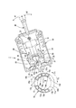
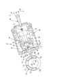
図1は、本実施形態のキャンセルカム構造10を有する回転コネクタ装置2を示す斜視図である。また、図2は、ステアリングホイール側から見たキャンセル機構1の中立状態を示す説明図であり、図3は、同じくステアリングホイール側から見たキャンセル機構1の左折指示状態を示す説明図である。
図1は、本実施形態のキャンセルカム構造10を有する回転コネクタ装置2を示す斜視図である。また、図2は、ステアリングホイール側から見たキャンセル機構1の中立状態を示す説明図であり、図3は、同じくステアリングホイール側から見たキャンセル機構1の左折指示状態を示す説明図である。
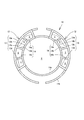
また、図4は、コンビネーションスイッチ側(車体側)から見たキャンセルカム構造10の平面図であり、図5(a)は、コンビネーションスイッチ側(車体側)から見たキャンセルカム構造10の斜視図、図5(b)は、図5(a)におけるA-A断面図である。
本実施形態の回転コネクタ装置2は、図1に示すように、回転コネクタ70にキャンセルカム構造10を備えた構成である。
図1における回転コネクタ装置2の下方には、図示しないステアリングホイールが備えられており、図1における回転コネクタ装置2の上面は、図示しない車体側のコンビネーションスイッチに取り付けられている。また、回転コネクタ装置2の中空部Hには、図示しないステアリングシャフトが挿入される。
図1における回転コネクタ装置2の下方には、図示しないステアリングホイールが備えられており、図1における回転コネクタ装置2の上面は、図示しない車体側のコンビネーションスイッチに取り付けられている。また、回転コネクタ装置2の中空部Hには、図示しないステアリングシャフトが挿入される。
回転コネクタ70は、主に固定ケース71と、回転ケース72と、図示しないフラットケーブルとで構成している。
この固定ケース71は、環状の固定側リング板71a及び該固定側リング板71aの外周縁から垂直に図1の下方に延びる外周筒部71bで構成し、図1の上方に設けられた車体側の上記コンビネーションスイッチに固定されている。
この固定ケース71は、環状の固定側リング板71a及び該固定側リング板71aの外周縁から垂直に図1の下方に延びる外周筒部71bで構成し、図1の上方に設けられた車体側の上記コンビネーションスイッチに固定されている。
また、回転ケース72は、図示しない環状の回転側リング板及び該回転側リング板の内周縁から図1の上方に向かって垂直に延びる円筒状の内周筒部72bで構成している。また、図1の下方に備えられた上記ステアリングホイールに固定され、ステアリングホイールと共に回動する。なお、回転コネクタ装置2は、回転ケース72が上側となるように車載される。
また、固定ケース71の固定側リング板71a及び外周筒部71bと、回転ケース72の回転側リング板及び内周筒部72bとで、フラットケーブルを収容する収容空間を構成している。このフラットケーブルは、収容空間に巻き回されて収容されており、固定ケース71側と回転ケース72側とを電気的に接続している。さらに、回転ケース72の内周筒部72bには、キャンセルカム構造10が取り付けられており、ステアリングホイールと共に一体に回動する構成である。
本実施形態のキャンセル機構1は、図2及び図3に示すように、上述のキャンセルカム構造10、ブラケット30、ターンレバー40及びラチェット20で構成している。
本実施形態のキャンセルカム構造10は、プラスチック製で、図4及び図5に示すように、ステアリングシャフトの挿入を許容する径を有するともに、概ね、ステアリングシャフトの軸方向Xに延びる円筒状の内筒11aと、該内筒11aと中心軸が同一で該内筒11aよりも径の大きい円筒状の外筒11bとで筒状に形成している。なお、ステアリングシャフトの軸中心と、内筒11a及び外筒11bの中心軸とが一致する構成である。
さらに、キャンセルカム構造10は、中心軸方向に突出したカム部12を左右に対称に備えている。一方の側のカム部12は、筒状の外壁13と該外壁13で囲まれた囲繞空間Sを分断する分断壁14とで構成している。
この外壁13は、外周カム壁13aと内側壁13bと連結カム壁13c,13dとで囲まれた筒状に形成している。
外周カム壁13aは、後述するラチェット20のキャンセルカム側端部24が接触する、ステアリングシャフトの軸方向Xに垂直な任意の断面が上記中心軸を中心とすると共に一定の径を有する円弧状であり、該軸方向Xに一様に延びる形状に形成している。
外周カム壁13aは、後述するラチェット20のキャンセルカム側端部24が接触する、ステアリングシャフトの軸方向Xに垂直な任意の断面が上記中心軸を中心とすると共に一定の径を有する円弧状であり、該軸方向Xに一様に延びる形状に形成している。
また、内側壁13bは、外周カム壁13aと同様、該任意の断面の形状が上記中心軸を中心とすると共に外周カム壁13aの径より小さい一定の径を有する円弧状であり、上記軸方向Xに一様に延びる形状に形成している。
さらに、連結カム壁13c,13dは、外周カム壁13a及び内側壁13bの端部同士を連結する、軸方向Xに沿って直立する平板状に形成している。
さらに、連結カム壁13c,13dは、外周カム壁13a及び内側壁13bの端部同士を連結する、軸方向Xに沿って直立する平板状に形成している。
また、分断壁14は、第1分断壁14aと第2分断壁14bと第2分断壁14cとで構成している。分断壁14(第1分断壁14a、第2分断壁14b、及び、第2分断壁14c)は、全て同じ厚みを有する平板状に形成しており、キャンセルカム構造10の軸方向X及び径方向に沿って直立するように配置されている。
また、分断壁14は、図5(b)に示すように、軸方向Xにおけるカム部12の上端12Uから下端12Dにわたって設けられ、外周カム壁13aと内側壁13bとの間を接続している。さらに、分断壁14は、外壁13によって囲まれた囲繞空間Sをキャンセルカム構造10の周方向に4等分するように、周方向に等間隔に配置している。
図2におけるキャンセルカム構造10の右側の近傍には、キャンセル機構内蔵ボディ50のボディ本体51が車体側に固定された状態に設けられている。このキャンセル機構内蔵ボディ50は、下部側のボディ本体51と、このボディ本体51の上面に装着される図示しないカバーとで構成している。
キャンセル機構内蔵ボディ50のボディ本体51の内部には、ブラケット30、ターンレバー40及びラチェット20が配置されている。
このブラケット30は、ブラケット軸部31を中心に、図2の矢印A1及びA2方向に回動可能に設けられている。ブラケット30の上面部には、キャンセル用の2個の係合部32,33を有するバックプレート34が設けられている。
このブラケット30は、ブラケット軸部31を中心に、図2の矢印A1及びA2方向に回動可能に設けられている。ブラケット30の上面部には、キャンセル用の2個の係合部32,33を有するバックプレート34が設けられている。
このバックプレート34は、図2中、矢印C1及び矢印C2方向に移動可能に設けられていると共に、通常時、バックスプリング35により、図2に示すバックスプリング35の平衡位置に保持されている。2個の係合部32,33は、キャンセルカム構造10側から見てハの字形に配置されている。
また、ブラケット30の先端部側(キャンセルカム構造10側)には、山形状をなしコンビネーションスイッチ側に突出しているガイド凸部36(図3参照)が形成されている。さらに、そのガイド凸部36の両側に当該ガイド凸部36より低いガイド凹部37が形成されている。
ブラケット30の上面部の先端部側にはラチェット20が配置されていて、このラチェット20は、図示しないカバーにより上方から覆われている。ラチェット20の長手方向のほぼ中間部には上下方向に突出するラチェット軸部21がラチェット20と一体に設けられていて、ラチェット20は、ラチェット軸部21を中心として揺動可能となっている。
ラチェット軸部21の下部は、上記ブラケット30の先端部側に挿入され、ラチェット軸部21の上部は、カバーの内面に形成されたガイド溝52aに移動可能に挿入されている。ガイド溝52aは、ブラケット30の回動中心であるブラケット軸部31の中心と、キャンセルカム構造10の回動中心とを結ぶ線に沿う方向に延設されている。
ラチェット20の下部にはスプリング用凹部が形成されていて、このスプリング用凹部に、引張りコイルスプリングからなるラチェットスプリング22の中間部が挿入されている。ラチェットスプリング22の長手方向の両端部はボディ本体51に引っ掛けられていて、ラチェット20は、このラチェットスプリング22の付勢力によりキャンセルカム構造10側(図2の矢印D方向)に付勢されている。
ここで、ラチェット20は、上述のラチェット軸部21を中心に揺動が可能で、かつガイド溝52aに沿ってキャンセルカム構造10に対して近接及び離間する方向に移動可能に設けられている。ラチェット20において、キャンセルカム構造10側となるキャンセルカム側端部24は、ボディ本体51の開口部51aからキャンセルカム構造10側へ突出し、キャンセルカム構造10とは反対側の反キャンセルカム側端部25が、上記2個の係合部32,33間に位置している。
ターンレバー40及びブラケット30が、図2に示す中立位置Nに配置された状態では、ラチェット20のラチェット軸部21の下部は、ブラケット30の先端部側におけるガイド凸部36の先端部に対向する位置にあり、ラチェット20は、ラチェットスプリング22の付勢力に抗してキャンセルカム構造10から離間する方向(矢印Dとは反対方向)に変位している。
この中立状態では、キャンセルカム側端部24が、キャンセルカム構造10におけるカム部12の回動軌跡E(図2参照)の外側に位置している。また、ラチェット20の反キャンセルカム側端部25は、2個の係合部32,33間のほぼ中央に位置している。
この中立状態から、ターンレバー40が、例えば、左折指示方向である矢印A1方向へ回動操作されると、そのターンレバー40と共にブラケット30がブラケット軸部31を中心に同矢印A1方向へ回動され、図3に示す、左折指示位置Lに回動された状態となる。
さらに、上述のブラケット30の左折支持位置Lへの回動により、ラチェット20のラチェット軸部21の下部がガイド凸部36の先端から外れ、ガイド凸部36の斜面に沿って、裾野側へ移動すると共に、ラチェットスプリング22の付勢力により矢印D方向へ変位した状態となる。また、ラチェット20のキャンセルカム側端部24が、キャンセルカム構造10におけるカム部12の外側カム壁12a1にラチェットスプリング22の付勢力により勢いよく接触する。この接触により打音が発生する。
このとき、ラチェット20の反キャンセルカム側端部25は、一方の係合部32に近接もしくは接触した状態となる。また、前記ブラケット30の矢印A1方向への回動に伴い、図示しないターンシグナルスイッチは、左折用スイッチがオンされ、図示しない左折用のターンシグナルランプが点滅するようになる。
この左折指示位置Lの投入状態で、ステアリングホイールの回動により、キャンセルカム構造10が、ターンレバー40の指示方向と同じ左方向(矢印F1方向)(順方向)へ回動されると、カム部12がキャンセルカム側端部24に矢印F1方向から当接する。
この場合、ラチェット20は、ラチェット軸部21を中心にして、反キャンセルカム側端部25が近接した係合部32から離間する方向(矢印G1方向)に揺動するので、カム部12の矢印F1方向への通過を許容する。よって、ブラケット30及びターンレバー40は、左折指示位置Lに保持されたままとなる。
これに対して、図3の左折指示位置Lの左折指示状態で、ステアリングホイールの回動により、キャンセルカム構造10がターンレバー40の指示方向と反対の右方向(矢印F2方向)へ回動されると、カム部12がキャンセルカム側端部24に矢印F2方向から当接する。
この場合、ラチェット20は、ラチェット軸部21を中心にして、反キャンセルカム側端部25が、近接した係合部32に係合する矢印G2方向に振られるように回動するようになる。
この場合、ラチェット20は、ラチェット軸部21を中心にして、反キャンセルカム側端部25が、近接した係合部32に係合する矢印G2方向に振られるように回動するようになる。
このラチェット20の矢印G2方向への回動に伴い、反キャンセルカム側端部25が係合部32に係合して、ブラケット30を矢印A2方向へ回動させる回動力が作用する。これにより、ブラケット30及びターンレバー40が矢印A2方向へ回動して、図2に示す中立位置Nに戻され、以てキャンセル機構1によるセルフキャンセル動作がなされる。これに伴い、ターンシグナルスイッチの左折用スイッチはオフされ、左折用のターンシグナルランプは消灯される。
上述のキャンセル機構1の動作説明では、ターンレバー40が左折指示位置L方向へ回動操作された場合について説明したが、ターンレバー40が右折指示位置R方向へ回動操作された場合には、各部材の回動方向が逆方向になるのみで、基本的な動作は上記と同様であるので、説明は省略する。
上述したキャンセルカム構造10により、以下に述べる作用効果を奏する。
まず、キャンセルセルカム構造10のカム部12に外壁13で囲まれた囲繞空間Sを分断する分断壁14を備えたことで、カム部12の剛性が高くなり、ラチェット20のキャンセルカム側端部24がキャンセルカム構造10のカム部12に接触することによるカム部12の振動の範囲及び振幅を小さくすることができる。従って、キャンセルカム構造10とラチェット20との接触音(打音)を小さく抑えることができ、運転者の乗り心地を向上させることができる。
まず、キャンセルセルカム構造10のカム部12に外壁13で囲まれた囲繞空間Sを分断する分断壁14を備えたことで、カム部12の剛性が高くなり、ラチェット20のキャンセルカム側端部24がキャンセルカム構造10のカム部12に接触することによるカム部12の振動の範囲及び振幅を小さくすることができる。従って、キャンセルカム構造10とラチェット20との接触音(打音)を小さく抑えることができ、運転者の乗り心地を向上させることができる。
また、カム部12は中心軸方向に一様な形状であるので、上述の効果を発揮できるカム部12のプラスチック成形を容易にできる。
また、分断壁14を径方向に沿って直立するように設けたことにより、カム部12は、特に径方向の剛性が高くなり、ラチェット20のキャンセルカム側端部24がキャンセルカム構造10におけるカム部12の外周カム壁13aに径方向の外側から内側へ向かって接近し、接触する場合のカム部12の振動を大幅に抑制することができる。よって、ラチェット20がカム部12の中心軸に向かって接触する際に発生する接触音(打音)を大幅に小さく抑えることができる。
また、分断壁14を径方向に沿って直立するように設けたことにより、カム部12は、特に径方向の剛性が高くなり、ラチェット20のキャンセルカム側端部24がキャンセルカム構造10におけるカム部12の外周カム壁13aに径方向の外側から内側へ向かって接近し、接触する場合のカム部12の振動を大幅に抑制することができる。よって、ラチェット20がカム部12の中心軸に向かって接触する際に発生する接触音(打音)を大幅に小さく抑えることができる。
また、分断壁14によって分割されることで周方向に区分けされた外周カム壁13aの各部分の周方向の長さと、それと対向する内側壁13bの各部分の周方向の長さとが各々異なるため、外周カム壁13aの振動による内側壁13bの共振が起こり難い。従って、ラチェット20がカム部12に接触する際に発生する接触音(打音)を小さく抑えることができる。
また、カム部12に囲繞空間Sを分断する分断壁14を複数備えたことにより、分断壁14を1つだけ備えたキャンセルカム構造に比べて、キャンセルカム構造10のカム部12の剛性が高く、ラチェット20のキャンセルカム側端部24とキャンセルカム構造10のカム部12との接触によるカム部12の振動音をより小さくすることができる。
また、上述の如くキャンセルカム構造10は、ラチェット20のキャンセルカム側端部24がキャンセルカム構造10にカム部12に接触することによる振動を小さく抑えることができる。従って、回転コネクタ70本体に与える振動を小さく抑えた回転コネクタ装置2を構成することができる。
なお、上述の作用効果は、ターンレバー40を左折指示方向(或いは、右折指示方向)に回動操作してラチェット20がカム部12に接触する際のみならず、キャンセル機構1のセルフキャンセル動作が完了するまでの間におけるラチェット20とカム部12とのあらゆる接触により発生する接触音に対しても有効に発揮される。
この発明は、上述の本実施形態の構成のみに限定されるものではなく、多くの実施形態を得ることができる。
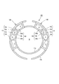
例えば、図6に示すように、連結カム壁13cと第1分断壁140aとの間隔、及び、第3分断壁140cと連結カム壁13dとの間隔が、第1分断壁140aと第2分断壁14bとの間隔、及び、第2分断壁14bと第3分断壁140cとの間隔より広い構成としてもよい。
例えば、図6に示すように、連結カム壁13cと第1分断壁140aとの間隔、及び、第3分断壁140cと連結カム壁13dとの間隔が、第1分断壁140aと第2分断壁14bとの間隔、及び、第2分断壁14bと第3分断壁140cとの間隔より広い構成としてもよい。
この場合、分断壁140で仕切られる内部空間が形状の異なる2種類以上の空間から構成されるので、キャンセルカム構造100のカム部120の固有振動数を2つ以上に分散させることができ、従って、キャンセルカム構造100のカム部120の共振を抑制することができる。
また、例えば、上述の本実施形態においては、キャンセルカム構造10を回転コネクタ70に備える構成であるが、これに限らず、キャンセルカム構造10を回転コネクタ70とは別部材に備えてもよい。
また、例えば、上述の本実施形態のキャンセルカム構造10は、キャンセル機構1のみならず、ラチェットとカム部12、120とが接触する他のあらゆるキャンセル機構に用いることができる。
また、例えば、上述の本実施形態のキャンセルカム構造10は、キャンセル機構1のみならず、ラチェットとカム部12、120とが接触する他のあらゆるキャンセル機構に用いることができる。
2…回転コネクタ装置
10,100…キャンセルカム構造
12,120…カム部
13a…外周カム壁
13b…内側壁
13c,13d…連結カム壁
14,140…分断壁
14a,140a…第1分断壁
14b…第2分断壁
14c,140c…第3分断壁
20…ラチェット
70…回転コネクタ
71…固定ケース
71a…固定側リング板
71b…外周筒部
72…回転ケース
72b…内周筒部
S…囲繞空間
X…軸方向
10,100…キャンセルカム構造
12,120…カム部
13a…外周カム壁
13b…内側壁
13c,13d…連結カム壁
14,140…分断壁
14a,140a…第1分断壁
14b…第2分断壁
14c,140c…第3分断壁
20…ラチェット
70…回転コネクタ
71…固定ケース
71a…固定側リング板
71b…外周筒部
72…回転ケース
72b…内周筒部
S…囲繞空間
X…軸方向
Claims (6)
- ラチェットの接触を許容するカム部を有すると共に、ステアリングシャフトの軸方向に対する径外側に配置され、該ステアリングシャフトに接続されたステアリングホイールの回動に伴って回動するキャンセルカム構造であって、
前記カム部を、
前記ラチェットの摺動を許容する外周カム壁と、
該外周カム壁より径内側の内側壁と、
前記外周カム壁及び前記内側壁の両端部同士を連結する連結カム壁とで構成し、
前記外周カム壁、前記内側壁、及び連結カム壁を前記軸方向に平行な方向に形成すると共に、前記外周カム壁、前記内側壁、及び連結カム壁で囲繞する囲繞空間を構成し、
前記外周カム壁、前記内側壁、及び連結カム壁のうち少なくとも1つに前記囲繞空間に向かって突出する突出部を備えた
キャンセルカム構造。 - 前記外周カム壁を、
前記軸方向に垂直な任意の断面の形状が、ステアリングシャフトの軸中心と前記任意の断面との交点を中心とすると共に、一定の径を有する円弧状であり、前記軸方向に一様に延びる構成とし、
前記内側壁を、
前記軸方向に垂直な任意の断面の形状が、前記軸中心と前記任意の断面との交点を中心とすると共に、前記外周カム壁の径より小さい一定の径を有する円弧状であり、前記軸方向に一様に延びる構成とし、
前記突出部を、
前記軸方向に沿って直立し、前記囲繞空間を分断する平板状の分断壁で構成する
請求項1に記載のキャンセルカム構造。 - 前記分断壁は、径方向に沿って直立する配置である
請求項2に記載のキャンセルカム構造。 - 前記分断壁を複数備える構成である
請求項2又は3に記載のキャンセルカム構造。 - 前記分断壁を所定間隔を隔てて複数備え、隣り合う前記連続カム壁と前記分断壁、並びに、隣り合う前記分断壁同士の間隔を少なくとも2種類以上に設定する
請求項3又は4に記載のキャンセルカム構造。 - 環状の固定側リング板及び該固定側リング板の外周縁から垂直に延びる円筒状の外周筒部で構成する固定ケースと、
環状の回転側リング板及び該回転リング板の内周縁から前記固定ケース側へ垂直に延びる円筒状の内周筒部で構成する回転ケースとを、
時計回り方向及び反時計回り方向に相対回転可能に嵌合し、
前記固定ケースの固定側リング板及び外周筒部と、前記回転ケースの回転側リング板及び内周筒部とで収容空間を構成し、
前記収容空間に、前記固定ケース側と前記回転ケース側とを電気的に接続するフラットケーブルを巻き回して収容した回転コネクタに、
請求項1から5のいずれかに記載のキャンセルカム構造を備えた
回転コネクタ装置。
Priority Applications (3)
| Application Number | Priority Date | Filing Date | Title |
|---|---|---|---|
| CN201180054822.2A CN103209862B (zh) | 2010-11-18 | 2011-11-18 | 复位凸轮结构及旋转连接器装置 |
| EP11841724.5A EP2641781B1 (en) | 2010-11-18 | 2011-11-18 | Cancel cam structure and rotary connector device |
| US13/898,194 US9434299B2 (en) | 2010-11-18 | 2013-05-20 | Cancel cam structure and rotatable connector device |
Applications Claiming Priority (2)
| Application Number | Priority Date | Filing Date | Title |
|---|---|---|---|
| JP2010257971A JP5138022B2 (ja) | 2010-11-18 | 2010-11-18 | キャンセルカム構造及び回転コネクタ装置 |
| JP2010-257971 | 2010-11-18 |
Related Child Applications (1)
| Application Number | Title | Priority Date | Filing Date |
|---|---|---|---|
| US13/898,194 Continuation US9434299B2 (en) | 2010-11-18 | 2013-05-20 | Cancel cam structure and rotatable connector device |
Publications (1)
| Publication Number | Publication Date |
|---|---|
| WO2012067238A1 true WO2012067238A1 (ja) | 2012-05-24 |
Family
ID=46084157
Family Applications (1)
| Application Number | Title | Priority Date | Filing Date |
|---|---|---|---|
| PCT/JP2011/076696 Ceased WO2012067238A1 (ja) | 2010-11-18 | 2011-11-18 | キャンセルカム構造及び回転コネクタ装置 |
Country Status (5)
| Country | Link |
|---|---|
| US (1) | US9434299B2 (ja) |
| EP (1) | EP2641781B1 (ja) |
| JP (1) | JP5138022B2 (ja) |
| CN (1) | CN103209862B (ja) |
| WO (1) | WO2012067238A1 (ja) |
Families Citing this family (2)
| Publication number | Priority date | Publication date | Assignee | Title |
|---|---|---|---|---|
| JP5224404B2 (ja) * | 2010-03-30 | 2013-07-03 | 古河電気工業株式会社 | 回転コネクタ装置 |
| JP7488327B2 (ja) | 2020-03-02 | 2024-05-21 | 古河電気工業株式会社 | キャンセルカム |
Citations (2)
| Publication number | Priority date | Publication date | Assignee | Title |
|---|---|---|---|---|
| JPS63159344U (ja) * | 1987-04-07 | 1988-10-19 | ||
| JP2010143460A (ja) | 2008-12-19 | 2010-07-01 | Tokai Rika Co Ltd | 車両用方向指示装置 |
Family Cites Families (5)
| Publication number | Priority date | Publication date | Assignee | Title |
|---|---|---|---|---|
| JPH079310Y2 (ja) * | 1986-06-16 | 1995-03-06 | アルプス電気株式会社 | タ−ンシグナルスイツチのキヤンセル機構 |
| GB9105837D0 (en) * | 1991-03-19 | 1991-05-01 | Lucas Ind Plc | Electrical switch assembly |
| JP2000003638A (ja) * | 1998-06-15 | 2000-01-07 | Sumitomo Wiring Syst Ltd | ケーブルリールとコンビネーションスイッチとの取付構造 |
| JP4139027B2 (ja) * | 1999-11-18 | 2008-08-27 | 株式会社東海理化電機製作所 | ターンシグナルのキャンセル装置 |
| JP2003127764A (ja) * | 2001-10-24 | 2003-05-08 | Niles Parts Co Ltd | コンビネーションスイッチのキャンセル構造 |
-
2010
- 2010-11-18 JP JP2010257971A patent/JP5138022B2/ja active Active
-
2011
- 2011-11-18 CN CN201180054822.2A patent/CN103209862B/zh active Active
- 2011-11-18 WO PCT/JP2011/076696 patent/WO2012067238A1/ja not_active Ceased
- 2011-11-18 EP EP11841724.5A patent/EP2641781B1/en active Active
-
2013
- 2013-05-20 US US13/898,194 patent/US9434299B2/en active Active
Patent Citations (2)
| Publication number | Priority date | Publication date | Assignee | Title |
|---|---|---|---|---|
| JPS63159344U (ja) * | 1987-04-07 | 1988-10-19 | ||
| JP2010143460A (ja) | 2008-12-19 | 2010-07-01 | Tokai Rika Co Ltd | 車両用方向指示装置 |
Non-Patent Citations (1)
| Title |
|---|
| See also references of EP2641781A4 * |
Also Published As
| Publication number | Publication date |
|---|---|
| JP2012106666A (ja) | 2012-06-07 |
| CN103209862B (zh) | 2015-11-25 |
| CN103209862A (zh) | 2013-07-17 |
| US9434299B2 (en) | 2016-09-06 |
| EP2641781A4 (en) | 2015-02-25 |
| EP2641781A1 (en) | 2013-09-25 |
| US20130292234A1 (en) | 2013-11-07 |
| JP5138022B2 (ja) | 2013-02-06 |
| EP2641781B1 (en) | 2016-08-17 |
Similar Documents
| Publication | Publication Date | Title |
|---|---|---|
| JP5041447B2 (ja) | 回転コネクタ装置 | |
| JP6083230B2 (ja) | シフト装置 | |
| JP5912693B2 (ja) | 自動二輪車におけるハンドルスイッチ及び自動二輪車 | |
| JP2011207402A5 (ja) | ||
| JP5224404B2 (ja) | 回転コネクタ装置 | |
| WO2018070340A1 (ja) | シフト装置 | |
| JP2010018116A (ja) | ブレーキペダル装置 | |
| JP5138022B2 (ja) | キャンセルカム構造及び回転コネクタ装置 | |
| JP2012106666A5 (ja) | ||
| JP6565796B2 (ja) | ステアリングホイール | |
| JP5690252B2 (ja) | シフト装置 | |
| JPWO2017159826A1 (ja) | 車両用ホイール | |
| JP6369988B2 (ja) | 車両用ドアミラー | |
| JP5659080B2 (ja) | シフト装置 | |
| JP6357378B2 (ja) | シフト装置 | |
| JP2015009747A (ja) | シフト装置 | |
| JP6099859B2 (ja) | 飲料容器支持装置 | |
| JP5659081B2 (ja) | シフト装置 | |
| JP2007269228A (ja) | コンソールボックス | |
| WO2024219278A1 (ja) | シフト装置 | |
| JP5195067B2 (ja) | 船外機のハンドル支持構造 | |
| JP2008251215A (ja) | 車両用ターンレバースイッチ装置 | |
| JP2023117635A (ja) | ステアリング装置 | |
| JP2017128309A (ja) | ステアリングホイール | |
| JP2006137288A (ja) | ステアリングホイール構造 |
Legal Events
| Date | Code | Title | Description |
|---|---|---|---|
| 121 | Ep: the epo has been informed by wipo that ep was designated in this application |
Ref document number: 11841724 Country of ref document: EP Kind code of ref document: A1 |
|
| REEP | Request for entry into the european phase |
Ref document number: 2011841724 Country of ref document: EP |
|
| WWE | Wipo information: entry into national phase |
Ref document number: 2011841724 Country of ref document: EP |
|
| NENP | Non-entry into the national phase |
Ref country code: DE |