WO2012070108A1 - ローラヘミング装置 - Google Patents
ローラヘミング装置 Download PDFInfo
- Publication number
- WO2012070108A1 WO2012070108A1 PCT/JP2010/070834 JP2010070834W WO2012070108A1 WO 2012070108 A1 WO2012070108 A1 WO 2012070108A1 JP 2010070834 W JP2010070834 W JP 2010070834W WO 2012070108 A1 WO2012070108 A1 WO 2012070108A1
- Authority
- WO
- WIPO (PCT)
- Prior art keywords
- roller
- bending
- bending roller
- workpiece
- main
- Prior art date
- Legal status (The legal status is an assumption and is not a legal conclusion. Google has not performed a legal analysis and makes no representation as to the accuracy of the status listed.)
- Ceased
Links
Images


Classifications
-
- B—PERFORMING OPERATIONS; TRANSPORTING
- B21—MECHANICAL METAL-WORKING WITHOUT ESSENTIALLY REMOVING MATERIAL; PUNCHING METAL
- B21D—WORKING OR PROCESSING OF SHEET METAL OR METAL TUBES, RODS OR PROFILES WITHOUT ESSENTIALLY REMOVING MATERIAL; PUNCHING METAL
- B21D39/00—Application of procedures in order to connect objects or parts, e.g. coating with sheet metal otherwise than by plating; Tube expanders
- B21D39/02—Application of procedures in order to connect objects or parts, e.g. coating with sheet metal otherwise than by plating; Tube expanders of sheet metal by folding, e.g. connecting edges of a sheet to form a cylinder
- B21D39/021—Application of procedures in order to connect objects or parts, e.g. coating with sheet metal otherwise than by plating; Tube expanders of sheet metal by folding, e.g. connecting edges of a sheet to form a cylinder for panels, e.g. vehicle doors
- B21D39/023—Application of procedures in order to connect objects or parts, e.g. coating with sheet metal otherwise than by plating; Tube expanders of sheet metal by folding, e.g. connecting edges of a sheet to form a cylinder for panels, e.g. vehicle doors using rollers
-
- B—PERFORMING OPERATIONS; TRANSPORTING
- B21—MECHANICAL METAL-WORKING WITHOUT ESSENTIALLY REMOVING MATERIAL; PUNCHING METAL
- B21D—WORKING OR PROCESSING OF SHEET METAL OR METAL TUBES, RODS OR PROFILES WITHOUT ESSENTIALLY REMOVING MATERIAL; PUNCHING METAL
- B21D19/00—Flanging or other edge treatment, e.g. of tubes
- B21D19/02—Flanging or other edge treatment, e.g. of tubes by continuously-acting tools moving along the edge
- B21D19/04—Flanging or other edge treatment, e.g. of tubes by continuously-acting tools moving along the edge shaped as rollers
- B21D19/043—Flanging or other edge treatment, e.g. of tubes by continuously-acting tools moving along the edge shaped as rollers for flanging edges of plates
Definitions
- the present invention relates to a roller hemming device that hemmes a workpiece using a roller.
- a flange in a standing state on a workpiece such as an automobile door sub-assembly is bent to a predetermined angle using a roller (preliminary bending) and then bent to a final angle (main bending).
- a roller hemming device for performing the above is widely known.
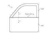
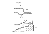
- the workpiece W to be processed by the roller hemming device is a door sub-assembly, and includes a door panel W10 made of a plurality of plate members, and a door frame W20 that protrudes upward from the door panel W10 to form a window frame. It comprises.
- the door frame W20 may interfere with the roller hemming device arranged in the window frame. For this reason, it is difficult to roll the roller along the belt line of the workpiece W.
- the door panel W10 has an upright flange (the right end portion in FIG. 6) and is placed on the lower mold B, and on the outer panel W11.
- the outer reinforcement W12 installed on the left side, the inner reinforcement W13 provided above the outer reinforcement W12 at a predetermined interval, and the inner panel W14 installed on the inner reinforcement W13 are provided. Therefore, the belt line of the work W has a structure having a relatively narrow gap between the outer panel W11 and the outer reinforcement W12, and the inner reinforcement W13 and the inner panel W14, and the work W interferes with the roller hemming device. It is difficult to perform hemming on the belt line of the workpiece W.
- FIG. 6 is an end view taken along line AA in FIG.
- roller hemming device which has (for example, refer patent document 1).
- the flange of the outer panel W ⁇ b> 11 in the roller 101 Since the portion that hemmes the workpiece W in contact with the mounting member 102 and the mounting member 102 to which the roller 101 is attached are largely separated from each other, bending occurs during processing, and it is difficult to achieve an appropriate hem thickness. . Further, since a large moment is applied to the mounting member 102 during processing, a problem such as deformation of the mounting member 102 occurs, resulting in an increase in time and cost required for maintenance of the roller hemming device 100 and the like. Further, since the outer diameter of the roller 101 is small, the successive bending of the flange of the outer panel W11 by the roller 101 partially increases the elongation of the flange, causing problems such as undulation of the flange.
- An object of the present invention is to provide a roller hemming device that can perform hemming satisfactorily and reduce the maintenance frequency even when the object to be processed is located in a relatively narrow place.
- the roller hemming device of the present invention sets a pre-bending roller for pre-bending a workpiece, a main-bending roller for main-bending the workpiece, and the postures of the preliminary-bending roller and the main-bending roller at desired positions and angles.
- An arm, and the pre-bending roller is disposed at a position where the axis of the pre-bending roller is inclined with respect to a horizontal direction and does not contact the workpiece during the main bending,
- the shaft center is inclined with respect to the horizontal direction so that the surface on the large-diameter side is located on the workpiece side during the final bending and the machining surface is horizontal.
- the preliminary bending roller and the main bending roller are arranged along the vertical direction, and their processing points are located in the vicinity of the axis of the arm. It is placed in.
- the roller hemming device further includes a backup roller that rotates following the rotation of the main bending roller, and the backup roller is a processing surface of the main bending roller in the diameter direction of the main bending roller. It is preferable to arrange so as to contact the opposite surface.
- the preliminary bending roller and the main bending roller are urged toward the work with a constant pressure and the work reaction force is absorbed when the work is pre-bending or main bending. Accordingly, it is preferable to further include means for equalizing the processing pressure.
- the present invention even when the object to be processed is located in a relatively narrow place, hemming can be performed satisfactorily and the maintenance frequency can be reduced.
- the figure which shows the roller hemming apparatus which concerns on this invention.
- the roller hemming apparatus 1 which is one Embodiment of the roller hemming apparatus which concerns on this invention is demonstrated.
- the roller hemming device 1 is a device that performs hemming on the belt line of the workpiece W.
- the workpiece W is a door sub-assembly in the manufacturing process of the automobile, and has an outer panel W11 installed on the lower mold B having an upright flange (right end portion in FIG. 6), and the flange on the outer panel W11.
- An outer reinforcement W12 installed on the left side, an inner reinforcement W13 provided above the outer reinforcement W12 at a predetermined interval, and an inner panel W14 installed on the inner reinforcement W13 (see FIG. 6). ).
- the lower mold B is a member for placing the workpiece W, and the workpiece W is placed so as to come into contact with the outer panel W11.
- the vertical direction and the horizontal direction in FIG. 1 are defined as the vertical direction and the horizontal direction of the roller hemming device 1.
- the up-down direction in FIG. 1 shall correspond with a perpendicular direction.
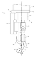
- the roller hemming device 1 includes a preliminary bending roller 10 that performs preliminary bending of the workpiece W, a main bending roller 20 that performs final bending of the workpiece W, and a driven rotation accompanying the rotation of the main bending roller 20.
- a support member 60 for supporting the air cylinder 50 and an arm 70 fixed to the support member 60 and capable of setting the postures of the pre-bending roller 10 and the main bending roller 20 to desired positions and angles are provided.
- the roller hemming device 1 rolls the pre-bending roller 10 along the belt line of the workpiece W by the arm 70 to perform the preliminary bending of the workpiece W a plurality of times, and then performs the main bending along the belt line of the workpiece W by the arm 70.
- the workpiece W is hemmed by rolling the bending roller 20 to perform the main bending of the workpiece W.
- the pre-bending roller 10 is a roller that performs “pre-bending” for bending the flange of the outer panel W11 of the work W to a predetermined angle.
- the pre-bending roller 10 is formed in a columnar shape, and is rotatably attached to the lower end portion of the attachment member 40 so that the shaft center forms a predetermined angle with respect to the horizontal direction.
- the pre-bending roller 10 is disposed on the left side of the lower end portion of the attachment member 40.
- the main bending roller 20 is a roller that performs a “main bending” for bending the flange of the outer panel W11 of the work W to a final angle (an angle at which the flange contacts the upper surface of the outer reinforcement W12) after the preliminary bending.
- the main bending roller 20 is rotatably attached to a midway portion in the vertical direction of the attachment member 40 such that the shaft center forms a predetermined angle with respect to the horizontal direction.
- the main bending roller 20 is formed in a truncated cone shape and is arranged so that the surface on the large diameter side is located on the right side.
- the main bending roller 20 is attached to the attachment member 40 in a state where the processing surface (the outer peripheral surface located at the lower end) is inclined so as to be horizontal.
- the main bending roller 20 is arranged on the opposite side (right side) of the attachment member 40 in the left-right direction with respect to the preliminary bending roller 10.
- the main bending roller 20 and the pre-bending roller 10 are arranged on the upper and lower sides, and are arranged on the right side and the left side of the mounting member 40, respectively.
- the backup roller 30 is a roller that comes into contact with the outer peripheral surface of the main bending roller 20 and rotates following the rotation of the main bending roller 20.
- the backup roller 30 is formed in a substantially cylindrical shape, and is rotatably attached to the attachment member 40 so that the axis is horizontal.
- the backup roller 30 is formed so as to incline along the outer peripheral surface of the main bending roller 20 from the right end portion to the middle portion on the outer peripheral surface, and the outer peripheral surface located at the lower end of the inclined portion and the main bending roller 20. It arrange
- the backup roller 30 is disposed on the upper side of the main bending roller 20 so as to come into contact with the surface of the main bending roller 20 opposite to the processing surface in the diameter direction of the main bending roller 20.
- the backup roller 30 since the backup roller 30 is driven to rotate along with the rotation of the main bending roller 20 during hemming, the rotation of the main bending roller 20 is not hindered.
- the backup roller 30 is arranged so that the axis is horizontal.
- the backup roller 30 only needs to be driven and rotated along with the rotation of the main bending roller 20, for example, the axis is vertical. It is also possible to arrange the backup roller 30 in such a manner.
- the mounting member 40 is a member that extends in the vertical direction while being bent, and each of the rollers 10, 20, and 30 is rotatably mounted.
- the attachment member 40 includes a first bent portion 41 to which the preliminary bending roller 10 is attached, a second bent portion 42 to which the main bending roller 20 is attached, and a linear portion 43 to which the backup roller 30 is attached.
- the first bent portion 41 extends from the connecting portion with the second bent portion 42 toward the lower left so as to form a predetermined angle with respect to the vertical direction according to the inclination angle of the preliminary bending roller 10.
- a pre-bending roller 10 is attached to the left side of the extended end of the first bent portion 41, and the pre-bending roller 10 has a processing point near the axis of the arm 70 (dashed line C in FIG. 1). It is arranged to be located.
- the “axial center of the arm 70” refers to the center of the contact surface between the support member 60 and the arm 70, that is, the center of the pressing surface of the support member 60 by the arm 70 during hemming. It is a straight line that extends.
- the second bent portion 42 extends from the connecting portion with the straight portion 43 toward the lower right so as to form a predetermined angle with respect to the vertical direction according to the inclination angle of the main bending roller 20.
- the protruding end portion and the base end portion (upper end portion) of the first bent portion 41 are joined.
- the second bent portion 42 extends so as to pass through the axis of the arm 70.
- the main bending roller 20 is attached to the right side of the second bent portion 42, and the main bending roller 20 is disposed so that the processing point is located near the axis of the arm 70.
- the straight line portion 43 extends linearly in the vertical direction, and the lower end portion and the base end portion (upper end portion) of the second bent portion 42 are joined.
- a backup roller 30 is attached to the lower part of the straight portion 43, and the backup roller 30 is disposed on the right side of the straight portion 43 so as to come into contact with the main bending roller 20.
- the first bent portion 41 and the second bent portion 42 extend so as to pass through the axis of the arm 70 toward the lower left and the lower right, respectively.
- This makes it possible to place the processing points of the pre-bending roller 10 and the main bending roller 20 in the vicinity of the axis of the arm 70 while holding the pre-bending roller 10 and the main bending roller 20 in an inclined state. Therefore, during hemming, the mounting member 40 can be prevented from being bent due to a moment based on the machining reaction force and the amount of deviation from the axis of the arm 70 in the horizontal direction, and an appropriate hem thickness is realized. can do.
- the vicinity of the axis of the arm 70 refers to a range that includes not only the axis of the arm 70 but also the periphery of the axis of the arm 70. This is a range in which the roller hemming device 1 can achieve an appropriate hem plate thickness without suppressing the generation of a moment based on the amount of deviation from the center in the horizontal direction and without the mounting member 40 being bent.
- the air cylinder 50 is an air cylinder that urges the mounting member 40 downward with a predetermined pressure, and functions as a means for equalizing the processing pressure during hemming.
- the air cylinder 50 includes a fixed portion 51 attached to the support member 60 and a movable portion 52 that can move in the vertical direction with respect to the fixed portion 51.
- the fixed part 51 supports the movable part 52 and biases the movable part 52 downward with a predetermined pressure by compressed air.
- the upper end portion of the fixed portion 51 is fixed to the support member 60.
- the movable part 52 is composed of a piston or the like, and is supported by the fixed part 51 so as to be movable in the vertical direction.
- the movable portion 52 is disposed on the right side of the straight portion 43 in the mounting member 40 and is fixed to the upper portion of the straight portion 43.
- the movable part 52 supported by the fixed part 51 is urged downward with a predetermined pressure by the compressed air.
- the pre-bending roller 10 and the main bending roller 20 are urged downward with a predetermined pressure via the mounting member 40 fixed to the movable portion 52.
- the machining reaction force is absorbed by the stroke of the movable part 52 supported by the fixed part 51. Accordingly, it is possible to perform the preliminary bending of the workpiece W by the preliminary bending roller 10 and the main bending of the workpiece W by the main bending roller 20 with a constant pressure.
- the movement of the pre-bending roller 10 and the main bending roller 20 by the arm 70 is controlled so as to linearly reach a plurality of preset points. Therefore, when the object of the hemming process by the roller hemming device 1 is not a linear part like the belt line of the workpiece W in the present embodiment but a curved part, the object to be processed by the preliminary bending roller 10 and the main bending roller 20. Variations in the contact area with respect to. However, during hemming, the pre-bending roller 10 and the main bending roller 20 are urged downward at a constant pressure while the processing reaction force is absorbed by the air cylinder 50, so that the processing pressure can be equalized.
- the air cylinder is applied as the pressure equalizing means, but the present invention is not limited to this, and a hydraulic cylinder, a spring, or the like can be applied.
- the support member 60 includes a vertical portion 61 extending in the up-down direction and a horizontal portion 62 extending in the left-right direction, and the upper end portion of the vertical portion 61 and the left end portion of the horizontal portion 62 are coupled to each other. It is formed in a letter shape.
- the vertical portion 61 is disposed on the left side of the straight portion 43 in the mounting member 40 and supports the upper portion of the straight portion 43 so as to be slidable.
- the sliding mechanism is not limited, and an existing linear guide or the like can be applied.
- the horizontal portion 62 is disposed on the upper side of the air cylinder 50 and supports the air cylinder 50. Specifically, the lower end portion of the horizontal portion 62 and the upper end portion of the fixing portion 51 in the air cylinder 50 are fixed. Further, the upper end portion of the horizontal portion 62 is fixed to the distal end portion (lower end portion) of the arm 70.
- the vertical portion 61 supports the mounting member 40 so as to be slidable, and the horizontal portion 62 supports the air cylinder 50.
- the attachment member 40 fixed to the movable part 52 can move only up and down without moving left and right.
- the arm 70 is a robot arm that can be set to a desired position and angle, and is attached to the upper end portion of the horizontal portion 62 of the support member 60.
- the arm 70 can set the postures of the preliminary bending roller 10 and the main bending roller 20 to desired positions and angles via the support member 60 and the mounting member 40.
- the arm 70 rolls the preliminary bending roller 10 or the main bending roller 20 along the belt line of the workpiece W in a state where the preliminary bending roller 10 or the main bending roller 20 presses the flange of the outer panel W11 in the workpiece W. In this way, the work W is hemmed.
- preliminary bending of the workpiece W is performed.
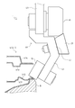
- the lower part of the pre-bending roller 10 is inserted by the arm 70 into the gap between the outer panel W11 and the outer reinforcement W12 and the inner reinforcement W13 and the inner panel W14 in the belt line of the workpiece W.
- the pre-bending roller 10 presses the flange of the outer panel W 11 in the work W and bends the flange to the angle of the processed surface of the pre-bending roller 10.
- the preliminary bending roller 10 rolls along the belt line of the workpiece W while pressing the flange, so that the flange is preliminarily bent as a whole.
- the mounting member 40 is bent, and when the flange is pre-bent, the first bent portion 41 of the mounting member 40 extends to the lower left toward the flange, and the pre-bending roller 10 is inclined. Is holding in. Accordingly, the preliminary bending roller 10 and the first bent portion 41 can enter the relatively narrow gap formed in the belt line of the workpiece W without interfering with the workpiece W, and the flange can be favorably formed. Can be pre-bent. Further, the length of the preliminary bending roller 10 in the axial direction can be shortened, and a large moment is not applied to the mounting portion of the mounting member 40 at the time of hemming, so that deformation of the mounting member 40 is prevented.
- the maintenance frequency of the roller hemming device 1 can be reduced. Further, at the time of preliminary bending of the flange, the second bent portion 42 of the mounting member 40 extends to the lower right so as to be separated from the flange, and the main bending roller 20 is disposed on the opposite side of the preliminary bending roller 10 in the left-right direction. keeping. Accordingly, the preliminary bending of the flange can be performed satisfactorily without causing the main bending roller 20 and the second bent portion 42 to interfere with the workpiece W.
- the preliminary bending of the workpiece W by the preliminary bending roller 10 is performed a plurality of times.
- the workpiece W is preliminarily bent twice.
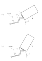
- the angle of the pre-bending roller 10 is set by the arm 70 so that the angle formed between the processed surface of the pre-bending roller 10 and the horizontal plane is ⁇ 1. .
- the angle between the flange and the other portion of the outer panel W11 at the time of preliminary bending (hereinafter simply referred to as “preliminary bending angle”) is ⁇ 1. W is produced.
- the pre-bending roller 10 is moved by the arm 70 so that the angle formed between the processed surface of the pre-bending roller 10 and the horizontal plane is ⁇ 2 ( ⁇ 2 ⁇ 1). Set the angle.
- the main bending roller 20 and the pre-bending roller 10 are arranged above and below, and the processing points of the main bending roller 20 and the pre-bending roller 10 are arranged near the axis of the arm 70.
- the width (length in the left-right direction) of the roller hemming device 1 can be suppressed, and when the workpiece W is pre-bent with the roller hemming device 1 tilted, interference with the door frame W20 (see FIG. 5) is avoided.
- the inclination angle of the roller hemming device 1 can be set in a wider range.
- the pre-bending roller 10 is inclined, the pre-bending angle can be set in a wider range (for example, 20 degrees to 90 degrees).
- the workpiece W can be subjected to preliminary bending a plurality of times, and compared with a case where the preliminary bending is performed once or only when the main bending is performed without performing the preliminary bending. It is possible to reduce the processing amount of the flange and suppress quality defects such as local elongation of the flange.
- the preliminary bending roller 10 is formed in a columnar shape, but the invention is not limited to this, and if it can be set to a desired preliminary angle, like the main bending roller 20, it has a truncated cone shape. It is also possible to form.
- the preliminary bending angle can be calculated as follows. First, based on the diameter of the pre-bending roller 10 and the flange elongation rate calculated from the processing amount of the flange in the pre-bending, the elongation amount of the flange at the time of pre-bending is calculated, and the elongation amount is a limit based on an empirical rule. Calculate the processing amount of the flange that does not exceed the value. Then, the number of times of preliminary bending is calculated from the calculated processing amount of the flange and the angle of the flange before hemming processing (90 degrees in the present embodiment), and the preliminary bending angle is obtained accordingly.
- the main bending of the workpiece W is performed.
- the roller hemming device 1 is reversed left and right from the time of preliminary bending.
- the lower portion of the main bending roller 20 is inserted by the arm 70 into the gap between the outer panel W11 and the outer reinforcement W12 and the inner reinforcement W13 and the inner panel W14 in the belt line of the workpiece W.
- the main bending roller 20 presses the flange of the outer panel W11 in the workpiece W in a state where the processing surface is horizontal, and bends the flange until it becomes horizontal (contacts the upper surface of the outer reinforcement W12).
- the main bending roller 20 rolls along the belt line of the workpiece W in a state where the flange is pressed, so that the flange is entirely bent.
- the pressing force of the main bending roller 20 against the workpiece W during the main bending is set to be larger than the pressing force of the preliminary bending roller 10 against the workpiece W during the preliminary bending. Therefore, the bending of the main bending roller 20 is prevented by arranging the backup roller 30 on the upper side of the main bending roller 20.
- the main bending roller 20 is formed in a truncated cone shape, and the surface on the large diameter side is positioned on the workpiece W side during the main bending. Therefore, the angle formed between the processed surface of the main bending roller 20 and the surface on the large diameter side is an acute angle. As a result, the main bending roller 20 can enter the relatively narrow gap formed in the belt line of the work W without the main bending roller 20 interfering with the work W, and the main bending roller can be properly bent. Can do. Further, since the outer diameter of the main bending roller 20 can be made relatively large, quality defects such as local elongation of the flange can be suppressed, and the durability of the main bending roller 20 can be improved.
- the length of the main bending roller 20 in the axial direction can be shortened, and a large moment is not applied to the mounting portion of the mounting member 40 in the mounting member 40 at the time of hemming, thereby preventing deformation of the mounting member 40.
- the maintenance frequency of the roller hemming device 1 can be reduced.
- the mounting member 40 is bent, and when the flange is bent, the second bent portion 42 of the mounting member 40 extends to the lower left toward the flange, and the bending roller 20 is held in an inclined state. ing. Accordingly, the processing surface of the frustoconical main bending roller 20 can be held in a horizontal state, and the main bending roller 20 and the second bent portion 42 can be well formed without interfering with the workpiece W.
- This bending can be performed. Further, during the final bending of the flange, the first bent portion 41 of the mounting member 40 extends to the lower right so as to be separated from the flange, and the preliminary bending roller 10 is disposed on the opposite side of the main bending roller 20 in the left-right direction. keeping. Thereby, the main bending of the flange can be performed satisfactorily without the preliminary bending roller 10 and the first bent portion 41 interfering with the workpiece W.
- the present invention can be used for a roller hemming device that performs hemming processing on a narrow portion such as a belt line of a door panel.
Landscapes
- Engineering & Computer Science (AREA)
- Mechanical Engineering (AREA)
- Bending Of Plates, Rods, And Pipes (AREA)
Abstract
Description
なお、図6は、図5におけるAA線端面図である。
また、ローラ101の外径が小さいため、ローラ101によるアウタパネルW11のフランジの逐次曲げによって、当該フランジの伸び量が部分的に大きくなり、フランジが波打つ等の問題が生じる。
ローラヘミング装置1は、ワークWのベルトラインに対してヘミング加工を施す装置である。
ワークWは、自動車の製造過程におけるドアサブアッシーであり、直立した状態のフランジ(図6における右端部分)を有して下型B上に設置されるアウタパネルW11と、アウタパネルW11上であってフランジよりも左側に設置されるアウタリインフォースW12と、アウタリインフォースW12と所定の間隔を空けて上方に設けられるインナリインフォースW13と、インナリインフォースW13上に設置されるインナパネルW14とを具備する(図6参照)。
下型Bは、ワークWを載置するための部材であり、アウタパネルW11と接触するようにワークWが載置される。
なお、図1における上下方向、及び左右方向をローラヘミング装置1の上下方向、及び左右方向と規定する。また、図1における上下方向は、鉛直方向と一致するものとする。
ローラヘミング装置1は、アーム70によって予備曲げローラ10をワークWのベルトラインに沿って転動させてワークWの予備曲げを複数回行った後、アーム70によってワークWのベルトラインに沿って本曲げローラ20を転動させてワークWの本曲げを行うことで、ワークWに対してヘミング加工を施す。
このように、本曲げローラ20及び予備曲げローラ10は、それぞれ上下に配置されると共に、それぞれ取付部材40の右側及び左側に配置されている。
これにより、アウタパネルW11のフランジが本曲げローラ20によって本曲げされる際に、加工反力によってフランジから離間するように撓む本曲げローラ20に対して、フランジに向けての力を付与することが可能となる。したがって、ヘミング加工時の本曲げローラ20の撓みを防止し、適正なヘム板厚を達成することができる。なお、バックアップローラ30は、ヘミング加工時に、本曲げローラ20の回転に伴って従動回転するため、本曲げローラ20の回転を阻害することはない。
また、本実施形態においては、軸心が水平となるようにバックアップローラ30を配置したが、バックアップローラ30が本曲げローラ20の回転に伴って従動回転すればよく、例えば、軸心が鉛直となるようにバックアップローラ30を配置することも可能である。
ここで、「アーム70の軸心」とは、支持部材60とアーム70との接触面の中心部、つまり、ヘミング加工時におけるアーム70による支持部材60の押圧面の中心部、から鉛直方向に延長する直線である。
第二屈曲部42の右側には、本曲げローラ20が取り付けられており、本曲げローラ20は、その加工点がアーム70の軸心近傍に位置するように配置されている。
直線部43の下部には、バックアップローラ30が取り付けられており、バックアップローラ30は、本曲げローラ20と接触するように直線部43の右側に配置されている。
これにより、予備曲げローラ10及び本曲げローラ20を傾斜した状態で保持しつつ、予備曲げローラ10及び本曲げローラ20の加工点をアーム70の軸心近傍に配置することが可能となる。したがって、ヘミング加工時に、加工反力とアーム70の軸心から水平方向へのズレ量とに基づくモーメントが発生することによる取付部材40の撓みを防止することができ、適正なヘム板厚を実現することができる。
なお、ここでいう「アーム70の軸心近傍」とは、アーム70の軸心上のみならず、アーム70の軸心の周囲を含む範囲であり、ヘミング加工時に加工反力とアーム70の軸心から水平方向へのズレ量とに基づくモーメントの発生を抑制し、取付部材40が撓むことなく、ローラヘミング装置1が適正なヘム板厚を実現可能となる範囲である。
可動部52は、ピストン等から構成され、固定部51に上下方向へ移動可能に支持されている。可動部52は、取付部材40における直線部43の右側に配置されて、直線部43の上部に固定されている。
これにより、予備曲げローラ10によるワークWの予備曲げ、及び本曲げローラ20によるワークWの本曲げを一定の圧力で行うことが可能となる。
ここで、アーム70による予備曲げローラ10及び本曲げローラ20の移動は、予め設定された複数の点へ直線的に到達するように制御されている。そのため、ローラヘミング装置1によるヘミング加工の対象が、本実施形態におけるワークWのベルトラインのような直線部分ではなく、曲線部分である場合には、予備曲げローラ10及び本曲げローラ20の加工対象に対する接触面積にバラツキが生じる。
しかしながら、ヘミング加工時に、エアシリンダ50によって加工反力が吸収されつつ、予備曲げローラ10及び本曲げローラ20が一定の圧力で下方に付勢されるため、加工圧の均圧化を図ることができ、加工対象が曲線部分であっても加工圧のバラツキが生じることなく均等にヘミング加工を行うことができる。
なお、本実施形態においては、均圧化手段としてエアシリンダを適用したが、これに限定するものではなく、油圧シリンダ、又はバネ等を適用可能である。
また、水平部62の上端部は、アーム70の先端部(下端部)と固定されている。
これにより、エアシリンダ50の可動部52の動きに応じて、可動部52に固定された取付部材40が左右に移動することなく、上下にのみ移動することが可能となる。
図2に示すように、ワークWのベルトラインにおける、アウタパネルW11及びアウタリインフォースW12と、インナリインフォースW13及びインナパネルW14との隙間に、アーム70によって予備曲げローラ10の下部が挿入される。予備曲げローラ10は、ワークWにおけるアウタパネルW11のフランジを押圧し、予備曲げローラ10の加工面の角度までフランジを折り曲げる。そして、予備曲げローラ10は、フランジを押圧した状態で、ワークWのベルトラインに沿って転動することで、フランジが全体的に予備曲げされることとなる。
これにより、予備曲げローラ10及び第一屈曲部41がワークWに干渉することなく、ワークWのベルトラインに形成された比較的狭い隙間に予備曲げローラ10を進入させることができ、良好にフランジの予備曲げを行うことができる。更に、予備曲げローラ10の軸心方向における長さを短くすることができ、ヘミング加工時に、取付部材40における予備曲げローラ10の取り付け部分に大きなモーメントがかからないため、取付部材40の変形を防止し、ローラヘミング装置1のメンテナンス頻度を低減することができる。
また、フランジの予備曲げ時に、取付部材40の第二屈曲部42がフランジから離間するように右下へ延出する形となり、予備曲げローラ10とは左右方向における反対側で本曲げローラ20を保持している。
これにより、本曲げローラ20及び第二屈曲部42がワークWに干渉することなく、良好にフランジの予備曲げを行うことができる。
図3(b)に示すように、二回目の予備曲げにおいては、予備曲げローラ10の加工面と水平面との成す角度がθ2(θ2<θ1)となるように、アーム70によって予備曲げローラ10の角度を設定する。そして、上記の通りにワークWの予備曲げを行うことで、予備曲げ角度がθ2であるワークWが作製される。
なお、図3においては、説明の便宜上、ワークWのアウタパネルW11、及びローラヘミング装置1の予備曲げローラ10のみを図示している。
これにより、ローラヘミング装置1の幅(左右方向の長さ)を抑制でき、ローラヘミング装置1を傾斜させてワークWの予備曲げを行う際に、ドアフレームW20(図5参照)の干渉を避け、ローラヘミング装置1の傾斜角度をより広い範囲で設定可能となる。加えて、予備曲げローラ10は、傾斜しているため、予備曲げ角度をより広い範囲(例えば、20度~90度)で設定することができる。したがって、上記のように、ワークWの予備曲げを複数回行うことができ、予備曲げを一回行う場合、又は予備曲げを行わずに本曲げのみを行う場合と比較して、一回あたりのフランジの加工量を小さくして、フランジの局部伸び等の品質不良を抑制することができる。
なお、本実施形態においては、予備曲げローラ10を円柱状に形成したが、これに限定するものではなく、所望の予備角度に設定することができれば、本曲げローラ20と同様に円錐台状に形成することも可能である。
まず、予備曲げローラ10の径、及び予備曲げにおけるフランジの加工量から算出されるフランジの伸び率に基づいて、予備曲げ時のフランジの伸び量を算出し、当該伸び量が経験則に基づく限界値を超えないようなフランジの加工量を算出する。
そして、算出されたフランジの加工量、及びヘミング加工前のフランジの角度(本実施形態においては、90度)から予備曲げの回数が算出され、それに伴って予備曲げ角度が求められる。
図4に示すように、アーム70が水平に約180度回転することにより、ローラヘミング装置1が予備曲げ時から左右に反転した状態となる。そして、ワークWのベルトラインにおける、アウタパネルW11及びアウタリインフォースW12と、インナリインフォースW13及びインナパネルW14との隙間に、アーム70によって本曲げローラ20の下部が挿入される。本曲げローラ20は、その加工面が水平となった状態で、ワークWにおけるアウタパネルW11のフランジを押圧し、フランジを水平になる(アウタリインフォースW12の上面に接触する)まで折り曲げる。そして、本曲げローラ20は、フランジを押圧した状態で、ワークWのベルトラインに沿って転動することで、フランジが全体的に本曲げされることとなる。
なお、本曲げ時における本曲げローラ20のワークWに対する押圧力は、予備曲げ時における予備曲げローラ10のワークWに対する押圧力よりも大きく設定される。そのため、本曲げローラ20の上側にバックアップローラ30を配置することによって、本曲げローラ20の撓みを防止している。
これにより、本曲げローラ20がワークWに干渉することなく、ワークWのベルトラインに形成された比較的狭い隙間に本曲げローラ20を進入させることができ、良好にフランジの本曲げを行うことができる。更に、本曲げローラ20の外径を比較的大きくすることができるため、フランジの局部伸び等の品質不良を抑制することができると共に、本曲げローラ20の耐久性を向上させることができる。更に、本曲げローラ20の軸心方向における長さを短くすることができ、ヘミング加工時に、取付部材40における本曲げローラ20の取り付け部分に大きなモーメントがかからないため、取付部材40の変形を防止し、ローラヘミング装置1のメンテナンス頻度を低減することができる。
また、取付部材40が屈曲しており、フランジの本曲げ時に、取付部材40の第二屈曲部42がフランジに向けて左下へ延出する形となり、本曲げローラ20を傾斜した状態で保持している。
これにより、円錐台状の本曲げローラ20の加工面を水平にした状態で保持することができると共に、本曲げローラ20及び第二屈曲部42がワークWに干渉することなく、良好にフランジの本曲げを行うことができる。
また、フランジの本曲げ時に、取付部材40の第一屈曲部41がフランジから離間するように右下へ延出する形となり、本曲げローラ20とは左右方向における反対側で予備曲げローラ10を保持している。
これにより、予備曲げローラ10及び第一屈曲部41がワークWに干渉することなく、良好にフランジの本曲げを行うことができる。
10 予備曲げローラ
20 本曲げローラ
30 バックアップローラ
40 取付部材
41 第一屈曲部
42 第二屈曲部
43 直線部
50 エアシリンダ
51 固定部
52 可動部
60 支持部材
61 垂直部
62 水平部
70 アーム
Claims (3)
- ワークの予備曲げを行う予備曲げローラと、
ワークの本曲げを行う本曲げローラと、
前記予備曲げローラ及び前記本曲げローラの姿勢を所望の位置及び角度に設定するアームと、を具備するローラヘミング装置であって、
前記予備曲げローラは、その軸心が水平方向に対して傾斜すると共に、本曲げ時に前記ワークと接触しない位置に配置され、
前記本曲げローラは、円錐台状に形成され、本曲げ時に大径側の表面が前記ワーク側に位置して加工面が水平となるように、軸心が水平方向に対して傾斜すると共に、予備曲げ時に前記ワークと接触しない位置に配置され、
前記予備曲げローラ及び前記本曲げローラは、上下方向に沿って配置されると共に、それらの加工点が前記アームの軸心近傍に位置するように配置されるローラヘミング装置。 - 前記本曲げローラの回転に伴って従動回転するバックアップローラを更に具備し、
前記バックアップローラは、前記本曲げローラの直径方向において、前記本曲げローラにおける加工面とは反対側の面に接触するように配置される請求項1に記載のローラヘミング装置。 - 前記ワークの予備曲げ又は本曲げの際に、前記予備曲げローラ及び前記本曲げローラを一定の圧力で前記ワークに向けて付勢すると共に、加工反力を吸収することによって、加工圧を均圧化する手段を更に具備する請求項1又は請求項2に記載のローラヘミング装置。
Priority Applications (5)
| Application Number | Priority Date | Filing Date | Title |
|---|---|---|---|
| EP10859903.6A EP2644295B1 (en) | 2010-11-22 | 2010-11-22 | Roller hemming device |
| JP2012545552A JP5556899B2 (ja) | 2010-11-22 | 2010-11-22 | ローラヘミング装置 |
| CN201080070255.5A CN103221161B (zh) | 2010-11-22 | 2010-11-22 | 滚子卷边装置 |
| US13/988,666 US9132466B2 (en) | 2010-11-22 | 2010-11-22 | Roller hemming device |
| PCT/JP2010/070834 WO2012070108A1 (ja) | 2010-11-22 | 2010-11-22 | ローラヘミング装置 |
Applications Claiming Priority (1)
| Application Number | Priority Date | Filing Date | Title |
|---|---|---|---|
| PCT/JP2010/070834 WO2012070108A1 (ja) | 2010-11-22 | 2010-11-22 | ローラヘミング装置 |
Publications (1)
| Publication Number | Publication Date |
|---|---|
| WO2012070108A1 true WO2012070108A1 (ja) | 2012-05-31 |
Family
ID=46145485
Family Applications (1)
| Application Number | Title | Priority Date | Filing Date |
|---|---|---|---|
| PCT/JP2010/070834 Ceased WO2012070108A1 (ja) | 2010-11-22 | 2010-11-22 | ローラヘミング装置 |
Country Status (5)
| Country | Link |
|---|---|
| US (1) | US9132466B2 (ja) |
| EP (1) | EP2644295B1 (ja) |
| JP (1) | JP5556899B2 (ja) |
| CN (1) | CN103221161B (ja) |
| WO (1) | WO2012070108A1 (ja) |
Cited By (1)
| Publication number | Priority date | Publication date | Assignee | Title |
|---|---|---|---|---|
| CN119566166A (zh) * | 2024-11-19 | 2025-03-07 | 一汽-大众汽车有限公司 | 一种用于汽车门盖的三步压合模块和方法 |
Families Citing this family (9)
| Publication number | Priority date | Publication date | Assignee | Title |
|---|---|---|---|---|
| FR3012057B1 (fr) * | 2013-10-21 | 2016-02-19 | Peugeot Citroen Automobiles Sa | Assemblage par sertissage de deux pieces en tole ou aluminium et son procede d'obtention |
| KR101545855B1 (ko) * | 2013-11-28 | 2015-08-20 | 주식회사 성우하이텍 | 롤러 헤밍 장치 |
| CN107175276A (zh) * | 2017-06-21 | 2017-09-19 | 新乡市振英机械设备有限公司 | 一种筛框翻边机上的旋压定位机构 |
| JP6904876B2 (ja) * | 2017-10-16 | 2021-07-21 | トヨタ自動車株式会社 | ローラヘミング加工方法およびローラヘミング加工装置 |
| CN112792187A (zh) * | 2020-12-15 | 2021-05-14 | 柳州广菱汽车技术有限公司 | 车门包边模及其压料装置 |
| CN114833269A (zh) * | 2022-03-31 | 2022-08-02 | 环球传动泰州有限公司 | 一种高速滚针轴承外圈成型工艺 |
| CN116618534A (zh) * | 2023-05-30 | 2023-08-22 | 常州中车汽车零部件有限公司 | 一种安装金属波纹管用的机床主轴 |
| CN117225994B (zh) * | 2023-09-21 | 2026-01-27 | 贵州红阳机械有限责任公司 | 一种复合皮碗的翻边成型方法 |
| CN120055155B (zh) * | 2025-04-29 | 2025-07-18 | 山西鼎隆智装科技股份有限公司 | 一种异形蜂窝铝板封边加工装置 |
Citations (4)
| Publication number | Priority date | Publication date | Assignee | Title |
|---|---|---|---|---|
| JPS62212025A (ja) * | 1986-03-12 | 1987-09-18 | Hitachi Ltd | 冷間ロ−ル成形方法及び装置 |
| WO2000013816A1 (en) * | 1998-09-08 | 2000-03-16 | Tri Engineering Company Limited | Roller rolling type working device and roller rolling type working method |
| JP2010515584A (ja) * | 2007-01-15 | 2010-05-13 | エダック ゲーエムベーハー ウント コー. カーゲーアーアー | 金属板複合材、金属板を接合する方法および接合装置 |
| JP2010194568A (ja) * | 2009-02-25 | 2010-09-09 | Hirotec Corp | ヘミング装置およびヘミング加工方法 |
Family Cites Families (9)
| Publication number | Priority date | Publication date | Assignee | Title |
|---|---|---|---|---|
| JP2675347B2 (ja) | 1988-09-06 | 1997-11-12 | マツダ株式会社 | ヘミング成形装置 |
| JPH07314054A (ja) | 1994-05-23 | 1995-12-05 | Toyota Motor Corp | 多目的ローラーヘミング方法および装置 |
| JP3664085B2 (ja) | 2000-05-18 | 2005-06-22 | トヨタ車体株式会社 | ロールヘミング加工方法及びロールヘミング装置 |
| US6983633B2 (en) * | 2003-10-24 | 2006-01-10 | Ford Global Technologies, Llc | Apparatus for roll hemming with zero angle deflection |
| US7124611B2 (en) * | 2004-10-08 | 2006-10-24 | Valiant Corporation | Roller hemming machine |
| GB2439693B (en) * | 2005-04-27 | 2010-07-07 | Honda Motor Co Ltd | Roll hemming method and roll hemming apparatus |
| JP4908862B2 (ja) * | 2006-02-02 | 2012-04-04 | 本田技研工業株式会社 | 自動車用パネル材 |
| JP4996907B2 (ja) | 2006-10-20 | 2012-08-08 | 本田技研工業株式会社 | ローラヘミング加工方法 |
| CN101422795B (zh) * | 2008-12-19 | 2010-08-11 | 重庆长安汽车股份有限公司 | 一种汽车侧围包边机 |
-
2010
- 2010-11-22 EP EP10859903.6A patent/EP2644295B1/en not_active Not-in-force
- 2010-11-22 JP JP2012545552A patent/JP5556899B2/ja not_active Expired - Fee Related
- 2010-11-22 WO PCT/JP2010/070834 patent/WO2012070108A1/ja not_active Ceased
- 2010-11-22 CN CN201080070255.5A patent/CN103221161B/zh not_active Expired - Fee Related
- 2010-11-22 US US13/988,666 patent/US9132466B2/en not_active Expired - Fee Related
Patent Citations (4)
| Publication number | Priority date | Publication date | Assignee | Title |
|---|---|---|---|---|
| JPS62212025A (ja) * | 1986-03-12 | 1987-09-18 | Hitachi Ltd | 冷間ロ−ル成形方法及び装置 |
| WO2000013816A1 (en) * | 1998-09-08 | 2000-03-16 | Tri Engineering Company Limited | Roller rolling type working device and roller rolling type working method |
| JP2010515584A (ja) * | 2007-01-15 | 2010-05-13 | エダック ゲーエムベーハー ウント コー. カーゲーアーアー | 金属板複合材、金属板を接合する方法および接合装置 |
| JP2010194568A (ja) * | 2009-02-25 | 2010-09-09 | Hirotec Corp | ヘミング装置およびヘミング加工方法 |
Cited By (1)
| Publication number | Priority date | Publication date | Assignee | Title |
|---|---|---|---|---|
| CN119566166A (zh) * | 2024-11-19 | 2025-03-07 | 一汽-大众汽车有限公司 | 一种用于汽车门盖的三步压合模块和方法 |
Also Published As
| Publication number | Publication date |
|---|---|
| US20130247639A1 (en) | 2013-09-26 |
| EP2644295B1 (en) | 2017-09-20 |
| EP2644295A4 (en) | 2015-08-05 |
| CN103221161A (zh) | 2013-07-24 |
| CN103221161B (zh) | 2015-04-29 |
| EP2644295A1 (en) | 2013-10-02 |
| US9132466B2 (en) | 2015-09-15 |
| JPWO2012070108A1 (ja) | 2014-05-19 |
| JP5556899B2 (ja) | 2014-07-23 |
Similar Documents
| Publication | Publication Date | Title |
|---|---|---|
| JP5556899B2 (ja) | ローラヘミング装置 | |
| JP3598489B2 (ja) | ヘミング加工装置およびヘミング加工方法 | |
| US20110131778A1 (en) | Hemming device for wheel housing of vehicle | |
| JP5915816B2 (ja) | ローラヘミング加工装置およびローラヘミング加工方法 | |
| KR20200082996A (ko) | 지그형 헤밍 장치 | |
| US11253902B2 (en) | Hemming apparatus | |
| JP5975061B2 (ja) | カシメ装置及びカシメ方法 | |
| JP6512665B2 (ja) | ローラヘミング装置、及びローラヘミング方法 | |
| EP1447155B1 (en) | Roller-type hemming tool and method for performing a hemming operation | |
| KR101461794B1 (ko) | 소재형상 교정장치 | |
| JP4943666B2 (ja) | ロールヘミング加工方法及び加工装置 | |
| KR200461590Y1 (ko) | 관부재 단부 성형장치 | |
| JP2013154385A (ja) | ローラヘミング加工方法およびその装置 | |
| CN108246831A (zh) | 双排辊轧成型用开卷装置 | |
| JP2013544655A (ja) | 円形状カム装置を有する成形型 | |
| JP6111153B2 (ja) | 湾曲長尺材の製造方法、及び湾曲長尺材製造装置 | |
| JP2006088217A (ja) | ロールヘム加工装置 | |
| JP6057321B2 (ja) | ローラヘム加工装置 | |
| JP7392594B2 (ja) | ロールへミング加工方法及びロールへミング装置 | |
| JP5874389B2 (ja) | ローラーヘミング装置 | |
| JP2018099714A (ja) | パネルベンダー | |
| JP2015167959A (ja) | ロールヘミング加工装置 | |
| CN120644526A (zh) | 一种钣金件高精度折弯工艺 | |
| JP5118435B2 (ja) | ヘミング加工装置 | |
| RU2308340C1 (ru) | Валковая гибочная машина |
Legal Events
| Date | Code | Title | Description |
|---|---|---|---|
| 121 | Ep: the epo has been informed by wipo that ep was designated in this application |
Ref document number: 10859903 Country of ref document: EP Kind code of ref document: A1 |
|
| ENP | Entry into the national phase |
Ref document number: 2012545552 Country of ref document: JP Kind code of ref document: A |
|
| WWE | Wipo information: entry into national phase |
Ref document number: 13988666 Country of ref document: US |
|
| NENP | Non-entry into the national phase |
Ref country code: DE |
|
| REEP | Request for entry into the european phase |
Ref document number: 2010859903 Country of ref document: EP |
|
| WWE | Wipo information: entry into national phase |
Ref document number: 2010859903 Country of ref document: EP |