WO2012073348A1 - 非接触給電設備 - Google Patents
非接触給電設備 Download PDFInfo
- Publication number
- WO2012073348A1 WO2012073348A1 PCT/JP2010/071438 JP2010071438W WO2012073348A1 WO 2012073348 A1 WO2012073348 A1 WO 2012073348A1 JP 2010071438 W JP2010071438 W JP 2010071438W WO 2012073348 A1 WO2012073348 A1 WO 2012073348A1
- Authority
- WO
- WIPO (PCT)
- Prior art keywords
- power
- coil
- power supply
- supply device
- self
- Prior art date
- Legal status (The legal status is an assumption and is not a legal conclusion. Google has not performed a legal analysis and makes no representation as to the accuracy of the status listed.)
- Ceased
Links
Images


Classifications
-
- H—ELECTRICITY
- H04—ELECTRIC COMMUNICATION TECHNIQUE
- H04B—TRANSMISSION
- H04B5/00—Near-field transmission systems, e.g. inductive or capacitive transmission systems
- H04B5/20—Near-field transmission systems, e.g. inductive or capacitive transmission systems characterised by the transmission technique; characterised by the transmission medium
- H04B5/24—Inductive coupling
- H04B5/26—Inductive coupling using coils
- H04B5/266—One coil at each side, e.g. with primary and secondary coils
-
- B—PERFORMING OPERATIONS; TRANSPORTING
- B60—VEHICLES IN GENERAL
- B60L—PROPULSION OF ELECTRICALLY-PROPELLED VEHICLES; SUPPLYING ELECTRIC POWER FOR AUXILIARY EQUIPMENT OF ELECTRICALLY-PROPELLED VEHICLES; ELECTRODYNAMIC BRAKE SYSTEMS FOR VEHICLES IN GENERAL; MAGNETIC SUSPENSION OR LEVITATION FOR VEHICLES; MONITORING OPERATING VARIABLES OF ELECTRICALLY-PROPELLED VEHICLES; ELECTRIC SAFETY DEVICES FOR ELECTRICALLY-PROPELLED VEHICLES
- B60L3/00—Electric devices on electrically-propelled vehicles for safety purposes; Monitoring operating variables, e.g. speed, deceleration or energy consumption
- B60L3/0023—Detecting, eliminating, remedying or compensating for drive train abnormalities, e.g. failures within the drive train
- B60L3/003—Detecting, eliminating, remedying or compensating for drive train abnormalities, e.g. failures within the drive train relating to inverters
-
- B—PERFORMING OPERATIONS; TRANSPORTING
- B60—VEHICLES IN GENERAL
- B60L—PROPULSION OF ELECTRICALLY-PROPELLED VEHICLES; SUPPLYING ELECTRIC POWER FOR AUXILIARY EQUIPMENT OF ELECTRICALLY-PROPELLED VEHICLES; ELECTRODYNAMIC BRAKE SYSTEMS FOR VEHICLES IN GENERAL; MAGNETIC SUSPENSION OR LEVITATION FOR VEHICLES; MONITORING OPERATING VARIABLES OF ELECTRICALLY-PROPELLED VEHICLES; ELECTRIC SAFETY DEVICES FOR ELECTRICALLY-PROPELLED VEHICLES
- B60L53/00—Methods of charging batteries, specially adapted for electric vehicles; Charging stations or on-board charging equipment therefor; Exchange of energy storage elements in electric vehicles
- B60L53/10—Methods of charging batteries, specially adapted for electric vehicles; Charging stations or on-board charging equipment therefor; Exchange of energy storage elements in electric vehicles characterised by the energy transfer between the charging station and the vehicle
- B60L53/12—Inductive energy transfer
- B60L53/122—Circuits or methods for driving the primary coil, e.g. supplying electric power to the coil
-
- B—PERFORMING OPERATIONS; TRANSPORTING
- B60—VEHICLES IN GENERAL
- B60L—PROPULSION OF ELECTRICALLY-PROPELLED VEHICLES; SUPPLYING ELECTRIC POWER FOR AUXILIARY EQUIPMENT OF ELECTRICALLY-PROPELLED VEHICLES; ELECTRODYNAMIC BRAKE SYSTEMS FOR VEHICLES IN GENERAL; MAGNETIC SUSPENSION OR LEVITATION FOR VEHICLES; MONITORING OPERATING VARIABLES OF ELECTRICALLY-PROPELLED VEHICLES; ELECTRIC SAFETY DEVICES FOR ELECTRICALLY-PROPELLED VEHICLES
- B60L53/00—Methods of charging batteries, specially adapted for electric vehicles; Charging stations or on-board charging equipment therefor; Exchange of energy storage elements in electric vehicles
- B60L53/30—Constructional details of charging stations
- B60L53/35—Means for automatic or assisted adjustment of the relative position of charging devices and vehicles
- B60L53/36—Means for automatic or assisted adjustment of the relative position of charging devices and vehicles by positioning the vehicle
-
- B—PERFORMING OPERATIONS; TRANSPORTING
- B60—VEHICLES IN GENERAL
- B60R—VEHICLES, VEHICLE FITTINGS, OR VEHICLE PARTS, NOT OTHERWISE PROVIDED FOR
- B60R16/00—Electric or fluid circuits specially adapted for vehicles and not otherwise provided for; Arrangement of elements of electric or fluid circuits specially adapted for vehicles and not otherwise provided for
-
- H—ELECTRICITY
- H02—GENERATION; CONVERSION OR DISTRIBUTION OF ELECTRIC POWER
- H02J—ELECTRIC POWER NETWORKS; CIRCUIT ARRANGEMENTS OR SYSTEMS FOR SUPPLYING OR DISTRIBUTING ELECTRIC POWER; SYSTEMS FOR STORING ELECTRIC ENERGY
- H02J50/00—Circuit arrangements or systems for wireless supply or distribution of electric power
- H02J50/10—Circuit arrangements or systems for wireless supply or distribution of electric power using inductive coupling
- H02J50/12—Circuit arrangements or systems for wireless supply or distribution of electric power using inductive coupling of the resonant type
-
- H—ELECTRICITY
- H02—GENERATION; CONVERSION OR DISTRIBUTION OF ELECTRIC POWER
- H02J—ELECTRIC POWER NETWORKS; CIRCUIT ARRANGEMENTS OR SYSTEMS FOR SUPPLYING OR DISTRIBUTING ELECTRIC POWER; SYSTEMS FOR STORING ELECTRIC ENERGY
- H02J50/00—Circuit arrangements or systems for wireless supply or distribution of electric power
- H02J50/70—Circuit arrangements or systems for wireless supply or distribution of electric power involving the reduction of electric, magnetic or electromagnetic leakage fields
-
- H—ELECTRICITY
- H02—GENERATION; CONVERSION OR DISTRIBUTION OF ELECTRIC POWER
- H02J—ELECTRIC POWER NETWORKS; CIRCUIT ARRANGEMENTS OR SYSTEMS FOR SUPPLYING OR DISTRIBUTING ELECTRIC POWER; SYSTEMS FOR STORING ELECTRIC ENERGY
- H02J50/00—Circuit arrangements or systems for wireless supply or distribution of electric power
- H02J50/80—Circuit arrangements or systems for wireless supply or distribution of electric power involving the exchange of data, concerning supply or distribution of electric power, between transmitting devices and receiving devices
-
- H—ELECTRICITY
- H02—GENERATION; CONVERSION OR DISTRIBUTION OF ELECTRIC POWER
- H02J—ELECTRIC POWER NETWORKS; CIRCUIT ARRANGEMENTS OR SYSTEMS FOR SUPPLYING OR DISTRIBUTING ELECTRIC POWER; SYSTEMS FOR STORING ELECTRIC ENERGY
- H02J50/00—Circuit arrangements or systems for wireless supply or distribution of electric power
- H02J50/90—Circuit arrangements or systems for wireless supply or distribution of electric power involving detection or optimisation of position, e.g. alignment
-
- H—ELECTRICITY
- H02—GENERATION; CONVERSION OR DISTRIBUTION OF ELECTRIC POWER
- H02J—ELECTRIC POWER NETWORKS; CIRCUIT ARRANGEMENTS OR SYSTEMS FOR SUPPLYING OR DISTRIBUTING ELECTRIC POWER; SYSTEMS FOR STORING ELECTRIC ENERGY
- H02J7/00—Circuit arrangements for charging or discharging batteries or for supplying loads from batteries
- H02J7/90—Regulation of charging or discharging current or voltage
- H02J7/933—Regulation of charging or discharging current or voltage the cycle being controlled or terminated in response to electric parameters
-
- B—PERFORMING OPERATIONS; TRANSPORTING
- B60—VEHICLES IN GENERAL
- B60L—PROPULSION OF ELECTRICALLY-PROPELLED VEHICLES; SUPPLYING ELECTRIC POWER FOR AUXILIARY EQUIPMENT OF ELECTRICALLY-PROPELLED VEHICLES; ELECTRODYNAMIC BRAKE SYSTEMS FOR VEHICLES IN GENERAL; MAGNETIC SUSPENSION OR LEVITATION FOR VEHICLES; MONITORING OPERATING VARIABLES OF ELECTRICALLY-PROPELLED VEHICLES; ELECTRIC SAFETY DEVICES FOR ELECTRICALLY-PROPELLED VEHICLES
- B60L2270/00—Problem solutions or means not otherwise provided for
- B60L2270/10—Emission reduction
- B60L2270/14—Emission reduction of noise
- B60L2270/147—Emission reduction of noise electro magnetic [EMI]
-
- Y—GENERAL TAGGING OF NEW TECHNOLOGICAL DEVELOPMENTS; GENERAL TAGGING OF CROSS-SECTIONAL TECHNOLOGIES SPANNING OVER SEVERAL SECTIONS OF THE IPC; TECHNICAL SUBJECTS COVERED BY FORMER USPC CROSS-REFERENCE ART COLLECTIONS [XRACs] AND DIGESTS
- Y02—TECHNOLOGIES OR APPLICATIONS FOR MITIGATION OR ADAPTATION AGAINST CLIMATE CHANGE
- Y02T—CLIMATE CHANGE MITIGATION TECHNOLOGIES RELATED TO TRANSPORTATION
- Y02T10/00—Road transport of goods or passengers
- Y02T10/60—Other road transportation technologies with climate change mitigation effect
- Y02T10/70—Energy storage systems for electromobility, e.g. batteries
-
- Y—GENERAL TAGGING OF NEW TECHNOLOGICAL DEVELOPMENTS; GENERAL TAGGING OF CROSS-SECTIONAL TECHNOLOGIES SPANNING OVER SEVERAL SECTIONS OF THE IPC; TECHNICAL SUBJECTS COVERED BY FORMER USPC CROSS-REFERENCE ART COLLECTIONS [XRACs] AND DIGESTS
- Y02—TECHNOLOGIES OR APPLICATIONS FOR MITIGATION OR ADAPTATION AGAINST CLIMATE CHANGE
- Y02T—CLIMATE CHANGE MITIGATION TECHNOLOGIES RELATED TO TRANSPORTATION
- Y02T10/00—Road transport of goods or passengers
- Y02T10/60—Other road transportation technologies with climate change mitigation effect
- Y02T10/7072—Electromobility specific charging systems or methods for batteries, ultracapacitors, supercapacitors or double-layer capacitors
-
- Y—GENERAL TAGGING OF NEW TECHNOLOGICAL DEVELOPMENTS; GENERAL TAGGING OF CROSS-SECTIONAL TECHNOLOGIES SPANNING OVER SEVERAL SECTIONS OF THE IPC; TECHNICAL SUBJECTS COVERED BY FORMER USPC CROSS-REFERENCE ART COLLECTIONS [XRACs] AND DIGESTS
- Y02—TECHNOLOGIES OR APPLICATIONS FOR MITIGATION OR ADAPTATION AGAINST CLIMATE CHANGE
- Y02T—CLIMATE CHANGE MITIGATION TECHNOLOGIES RELATED TO TRANSPORTATION
- Y02T90/00—Enabling technologies or technologies with a potential or indirect contribution to GHG emissions mitigation
- Y02T90/10—Technologies relating to charging of electric vehicles
- Y02T90/12—Electric charging stations
-
- Y—GENERAL TAGGING OF NEW TECHNOLOGICAL DEVELOPMENTS; GENERAL TAGGING OF CROSS-SECTIONAL TECHNOLOGIES SPANNING OVER SEVERAL SECTIONS OF THE IPC; TECHNICAL SUBJECTS COVERED BY FORMER USPC CROSS-REFERENCE ART COLLECTIONS [XRACs] AND DIGESTS
- Y02—TECHNOLOGIES OR APPLICATIONS FOR MITIGATION OR ADAPTATION AGAINST CLIMATE CHANGE
- Y02T—CLIMATE CHANGE MITIGATION TECHNOLOGIES RELATED TO TRANSPORTATION
- Y02T90/00—Enabling technologies or technologies with a potential or indirect contribution to GHG emissions mitigation
- Y02T90/10—Technologies relating to charging of electric vehicles
- Y02T90/14—Plug-in electric vehicles
Definitions
- the present invention relates to a non-contact power supply facility, and more particularly to a non-contact power supply facility in which a power transmission unit and a power reception unit resonate via an electromagnetic field and perform power supply in a contactless manner.
- Electric vehicles such as electric cars and hybrid cars are attracting a great deal of attention as environmentally friendly vehicles. These vehicles are equipped with an electric motor that generates driving force and a rechargeable power storage device that stores electric power supplied to the electric motor.
- the hybrid vehicle is a vehicle in which an internal combustion engine is further mounted as a power source together with an electric motor, a vehicle in which a fuel cell is further mounted together with a power storage device as a DC power source for driving the vehicle.
- hybrid vehicles as in the case of electric vehicles, vehicles that can charge an in-vehicle power storage device from a power source outside the vehicle are known.
- a so-called “plug-in hybrid vehicle” is known in which a power storage device can be charged from a general household power source by connecting a power outlet provided in a house and a charging port provided in a vehicle with a charging cable.
- a power transmission method wireless power transmission that does not use a power cord or a power transmission cable has recently attracted attention.
- this wireless power transmission technology three technologies known as power transmission using electromagnetic induction, power transmission using microwaves, and power transmission using a resonance method are known.
- the resonance method is a non-contact power transmission technique in which a pair of resonators (for example, a pair of coils) are resonated in an electromagnetic field (near field) and transmitted via the electromagnetic field, and a large power of several kW is relatively long. It is also possible to transmit power over a distance (for example, several meters) (for example, see International Publication No. 2007/008646 pamphlet (Patent Document 1)).
- the resonance system Impedance changes. If a mismatch occurs between the impedance of the resonance system and the output impedance of the power supply device, the power transmission efficiency decreases and the reflected power to the power supply device increases. When the reflected power increases rapidly, the power supply device may be damaged by the reflected power.
- an object of the present invention is to provide a non-contact power supply that supplies power to a power receiving device in a non-contact manner when the power transmitting unit and the power receiving unit resonate via an electromagnetic field. In facilities, it is to prevent damage to the power supply device due to a sudden increase in reflected power.
- the non-contact power supply facility is a non-contact power supply facility that supplies power to a power receiving device including a power receiving unit in a non-contact manner, and includes a power supply device, a power transmission unit, a detection device, a discharge coil, and a connection Device.
- the power supply device generates power having a predetermined frequency.
- the power transmission unit receives power from the power supply device and resonates with the power reception unit via an electromagnetic field to transmit power to the power reception unit in a contactless manner.
- the detection device detects reflected power to the power supply device.
- the discharging coil discharges the electric power output from the power supply device to the outside. When the detected value of the reflected power exceeds a predetermined value, the connecting device electrically connects the discharge coil between the power supply device and the power transmission unit.
- the non-contact power supply facility further includes an electromagnetic shielding material.
- the electromagnetic shielding material is disposed around the discharge coil, and is opened in only one direction so that electric power can be discharged from the discharge coil to the outside.
- the emission coil and the electromagnetic shielding material are provided in the ground.
- the electromagnetic shielding material is disposed so that the opening portion faces the ground.
- the non-contact power supply facility further includes an impedance variable device.
- the impedance variable device is provided between the power supply device and the power transmission unit, and adjusts the input impedance of the resonance system configured by the power transmission unit and the power reception unit.
- the connection device electrically connects the emission coil between the impedance variable device and the power transmission unit when the detected value of the reflected power exceeds a predetermined value.
- the non-contact power supply facility further includes a control device.
- the control device activates the connecting device and changes the impedance of the variable impedance device to a predetermined value.
- the predetermined value is a value set in advance so that impedances of the discharge coil and the surrounding space are matched.
- the power transmission unit includes a primary coil and a primary self-resonant coil.
- the primary coil receives power from the power supply device.
- the primary self-resonant coil is fed by electromagnetic induction from the primary coil and generates an electromagnetic field.
- the power receiving unit includes a secondary self-resonant coil and a secondary coil.
- the secondary self-resonant coil receives power from the primary self-resonant coil by resonating with the primary self-resonant coil via the electromagnetic field.
- the secondary coil extracts and outputs the electric power received by the secondary self-resonant coil by electromagnetic induction.
- the power receiving device is mounted on a vehicle.
- the discharge coil when the detected value of the reflected power exceeds a predetermined value, the discharge coil is electrically connected between the power supply device and the power transmission unit, and the power output from the power supply device is the discharge coil. Is released to the outside. Therefore, according to the present invention, it is possible to prevent the power supply device from being damaged due to a sudden increase in reflected power.
- FIG. 1 is an overall configuration diagram of a non-contact power feeding system according to an embodiment of the present invention. It is the circuit diagram which showed an example of the circuit structure of the impedance matching device shown in FIG. It is a figure for demonstrating the principle of the power transmission by the resonance method. It is a figure for demonstrating arrangement
- 2 is a flowchart illustrating processing of an ECU when reflected power exceeding a threshold is detected in the power supply facility illustrated in FIG. 1. It is a flowchart which shows the process of ECU when the reflected electric power exceeding a threshold value is detected in the electric power feeding installation in the modification of embodiment. It is a whole block diagram of the non-contact electric power feeding system provided with the discharge resistance instead of the coil unit for discharge.
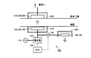
- FIG. 1 is an overall configuration diagram of a non-contact power feeding system according to an embodiment of the present invention.
- the non-contact power feeding system includes a power feeding facility 100 and a vehicle 200.
- the power supply facility 100 includes a power supply device 110, a power sensor 115, an impedance matching device 120, a primary coil 130, a primary self-resonant coil 140, a capacitor 150, and an electronic control unit (hereinafter referred to as “ECU”) 160. And a communication device 170. Power supply facility 100 further includes a coil 180, a discharge self-resonant coil 185, and a relay 190.
- the power supply device 110 generates power having a predetermined frequency.
- the power supply device 110 receives power from a system power supply (not shown) and generates power having a predetermined frequency of 1 MHz to several tens of MHz.
- Power supply device 110 controls generation and stop of power and output power in accordance with a command received from ECU 160.
- the power sensor 115 detects the reflected power in the power supply device 110 and outputs the detected value to the ECU 160.
- the reflected power is the power that is reflected from the power output from the power supply device 110 and returned to the power supply device 110.
- the power sensor 115 various known sensors capable of detecting reflected power in the power supply device can be used.
- the impedance matching unit 120 is provided between the power supply device 110 and the primary coil 130, and is configured to be able to change the internal impedance. Impedance matching unit 120 changes the impedance according to a command received from ECU 160, thereby changing primary coil 130, primary self-resonant coil 140 and capacitor 150, and secondary self-resonant coil 210, capacitor 220 and secondary coil 230 (of vehicle 200). The input impedance of the resonance system including that described later is matched with the output impedance of the power supply device 110.
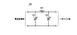
- FIG. 2 is a circuit diagram showing an example of the circuit configuration of the impedance matching unit 120 shown in FIG.
- impedance matching unit 120 includes variable capacitors 122 and 124 and a coil 126.
- Variable capacitor 122 is connected in parallel to power supply device 110 (FIG. 1).
- Variable capacitor 124 is connected in parallel to primary coil 130 (FIG. 1).
- Coil 126 is connected between connection nodes of variable capacitors 122 and 124 in one of a pair of power lines arranged between power supply device 110 and primary coil 130.
- impedance matching unit 120 the impedance is changed by changing the capacity of at least one of the variable capacitors 122 and 124 in accordance with a command received from the ECU 160 (FIG. 1). Thereby, impedance matching unit 120 matches the input impedance of the resonance system with the output impedance of power supply device 110 in accordance with a command received from ECU 160.
- the coil 126 may be a variable coil, and the impedance may be changed by changing the inductance of the variable coil.
- primary coil 130 is disposed substantially coaxially with primary self-resonant coil 140 at a predetermined interval from primary self-resonant coil 140.
- Primary coil 130 is magnetically coupled to primary self-resonant coil 140 by electromagnetic induction, and supplies high-frequency power supplied from power supply device 110 to primary self-resonant coil 140 by electromagnetic induction.
- the primary self-resonant coil 140 receives electric power from the primary coil 130 by electromagnetic induction, and transmits power to the secondary self-resonant coil 210 by resonating with a secondary self-resonant coil 210 (described later) mounted on the vehicle 200 via an electromagnetic field. To do.
- the primary self-resonant coil 140 is provided with a capacitor 150. Capacitor 150 is connected between both ends of primary self-resonant coil 140, for example. Then, the coil diameter and the number of turns of primary self-resonant coil 140 and the capacitance of capacitor 150 are appropriately designed so that the Q value (for example, Q> 100), the degree of coupling ⁇ , and the like are increased.
- the primary coil 130 is provided to facilitate power supply from the power supply device 110 to the primary self-resonant coil 140, and the power supply device 110 is directly connected to the primary self-resonant coil 140 without providing the primary coil 130. May be. Further, the stray capacitance of the primary self-resonant coil 140 may be used so that the capacitor 150 is not provided.
- the coil 180 is configured to be electrically connectable to the electric circuit between the impedance matching device 120 and the primary coil 130 by the relay 190.
- the coil 180 is disposed substantially coaxially with the discharge self-resonant coil 185 at a predetermined interval from the discharge self-resonant coil 185.
- the relay 190 When the relay 190 is turned on, the coil 180 receives electric power from the electric circuit between the impedance matching device 120 and the primary coil 130, and is magnetically coupled to the self-resonant coil 185 for emission by electromagnetic induction.
- the supplied electric power is supplied to the emission self-resonant coil 185 by electromagnetic induction.
- the emission self-resonant coil 185 is a coil for emitting the increased reflected power to the outside.
- the discharge self-resonant coil 185 has a coil diameter, the number of turns, and a capacitor capacity appropriately designed so that impedance is matched with the surrounding space.
- the coil 180 is also provided for facilitating power feeding to the discharge self-resonant coil 185, and the relay 190 is not provided in the electric path between the impedance matching unit 120 and the primary coil 130 without providing the coil 180.
- the discharge self-resonant coil 185 may be connectable via the. Further, a configuration may be adopted in which a capacitor is not provided in the emission self-resonant coil 185 using the stray capacitance of the emission self-resonant coil 185.
- the relay 190 is provided on the electric circuit for electrically connecting the coil 180 to the electric circuit between the impedance matching device 120 and the primary coil 130, and is turned on / off by the ECU 160.
- ECU 160 receives the detected value of reflected power from power sensor 115 when power is supplied from power supply facility 100 to vehicle 200, and the power reception status (power reception voltage, power reception current, etc.) on vehicle 200 received by communication device 170 is a communication device. Receive from 170. ECU 160 also receives information about the state of charge (hereinafter referred to as “SOC (State Of Charge)”) of power storage device 280 (described later) mounted on vehicle 200, power supply start / end command, and the like from communication device 170.
- SOC State Of Charge
- ECU160 performs a predetermined process by the software process by executing the program memorize
- CPU Central Processing Unit
- ECU 160 controls the operation of power supply device 110.
- ECU 160 adjusts the impedance of impedance matching unit 120 so that the input impedance of the resonance system matches the output impedance of power supply device 110.
- ECU 160 turns on relay 190 when the detected value of the reflected power exceeds a predetermined value during power feeding from power feeding facility 100 to vehicle 200.
- the coil 180 is electrically connected to the electric circuit between the impedance matching device 120 and the primary coil 130.
- a part of the reflected power is supplied to the coil 180, and the electric power is discharged from the emission self-resonant coil 185 to the outside.
- the power release process by the emission self-resonant coil 185 will be described in detail later.
- the communication device 170 is a communication interface for communicating with the vehicle 200.
- Communication device 170 receives information such as the power reception status of vehicle 200 and the SOC of power storage device 280 from vehicle 200 and outputs the information to ECU 160.
- vehicle 200 includes secondary self-resonant coil 210, capacitor 220, secondary coil 230, rectifier 260, charger 270, power storage device 280, power output device 285, ECU 290, and communication device 300. Including.
- the secondary self-resonant coil 210 receives power from the primary self-resonant coil 140 by resonating with the primary self-resonant coil 140 of the power supply facility 100 via an electromagnetic field.
- the secondary self-resonant coil 210 is provided with a capacitor 220.
- Capacitor 220 is connected between both ends of secondary self-resonant coil 210, for example. Then, the coil diameter and the number of turns of secondary self-resonant coil 210 and the capacitance of capacitor 220 are appropriately designed so that the Q value (for example, Q> 100), the degree of coupling ⁇ , and the like are increased.
- the secondary coil 230 is disposed substantially coaxially with the secondary self-resonant coil 210 at a predetermined interval from the secondary self-resonant coil 210.
- the secondary coil 230 can be magnetically coupled to the secondary self-resonant coil 210 by electromagnetic induction, takes out the electric power received by the secondary self-resonant coil 210 by electromagnetic induction, and outputs it to the rectifier 260.
- the secondary coil 230 is provided to facilitate the extraction of electric power from the secondary self-resonant coil 210, and the rectifier 260 is directly connected to the secondary self-resonant coil 210 without providing the secondary coil 230. You may connect. Further, the configuration may be such that the capacitor 220 is not provided by using the stray capacitance of the secondary self-resonant coil 210.
- the rectifier 260 rectifies the electric power (alternating current) extracted by the secondary coil 230.
- Charger 270 converts the DC power output from rectifier 260 into a charging voltage for power storage device 280 and outputs the voltage to power storage device 280.
- Power storage device 280 is a rechargeable DC power source, and is composed of, for example, a secondary battery such as lithium ion or nickel metal hydride.
- Power storage device 280 stores power received from charger 270 and also stores regenerative power generated by power output device 285. Then, power storage device 280 supplies the stored power to power output device 285. Note that a large-capacity capacitor can also be used as the power storage device 280.
- the power output device 285 generates the driving force for driving the vehicle 200 using the electric power stored in the power storage device 280.
- power output device 285 includes, for example, an inverter that receives electric power from power storage device 280, a motor driven by the inverter, a drive wheel driven by the motor, and the like.
- Power output device 285 may include a generator for charging power storage device 280 and an engine capable of driving the generator.
- the ECU 290 controls the operation of the charger 270 by software processing by executing a program stored in advance by the CPU and / or hardware processing by a dedicated electronic circuit.
- the communication device 300 is a communication interface for communicating with the power supply facility 100. Communication device 300 receives information such as the power reception status of vehicle 200 and the SOC of power storage device 280 from ECU 290 and transmits the information to power supply facility 100.
- this non-contact power feeding system in addition to primary self-resonant coil 140 and primary coil 130 for transmitting power to vehicle 200, discharge self-resonant coil 185 for discharging power output from power supply device 110 to the outside, and A coil 180 is provided.
- the relay 190 is turned on, and the coil 180 is electrically connected to the electric path between the impedance matching device 120 and the primary coil 130.
- the threshold value of the reflected power is appropriately set based on the specifications of the power supply device 110.
- FIG. 3 is a diagram for explaining the principle of power transmission by the resonance method.
- this resonance method in the same way as two tuning forks resonate, two LC resonance coils having the same natural frequency resonate in an electromagnetic field (near field), and thereby, from one coil. Electric power is transmitted to the other coil via an electromagnetic field.
- the primary coil 130 is connected to the power supply device 110, and high frequency power of 1 M to several tens MHz is supplied to the primary self-resonant coil 140 that is magnetically coupled to the primary coil 130 by electromagnetic induction.
- Primary self-resonant coil 140 forms an LC resonator with capacitor 150 and resonates with secondary self-resonant coil 210 having the same resonance frequency as primary self-resonant coil 140 via an electromagnetic field (near field). Then, energy (electric power) moves from the primary self-resonant coil 140 to the secondary self-resonant coil 210 via the electromagnetic field.
- the energy (power) transferred to the secondary self-resonant coil 210 is taken out by the secondary coil 230 that is magnetically coupled to the secondary self-resonant coil 210 by electromagnetic induction, and is supplied to the load 350 after the rectifier 260 (FIG. 1). Supplied.
- power transmission by the resonance method is realized when the Q value indicating the resonance intensity between the primary self-resonant coil 140 and the secondary self-resonant coil 210 is greater than 100, for example.
- FIG. 4 is a diagram for explaining the arrangement configuration of the power transmission unit and the discharge coil unit in the power supply facility 100.
- a unit composed of primary coil 130, primary self-resonant coil 140 and capacitor 150 (hereinafter referred to as “power transmission unit”) is described in a simplified column shape.
- a unit composed of secondary self-resonant coil 210, capacitor 220 and secondary coil 230 of vehicle 200 (hereinafter referred to as “power receiving unit”) is also described in a simplified column shape.
- a unit composed of the coil 180 and the discharge self-resonant coil 185 (hereinafter referred to as “discharge coil unit”) is also described in a simplified column shape.
- the power transmission unit and the discharge coil unit of power supply facility 100 are provided in the ground.
- a shield box 410 is disposed around the power transmission unit, and a shield box 420 is also disposed around the discharge coil unit.
- the shield box 410 is open on the ground side so that power can be transmitted to the power receiving unit of the vehicle 200.
- the shield box 420 is open on the opposite side to the ground so as to release electric power toward the ground. Thereby, it is possible to prevent unintended power from being discharged toward the ground when the power is discharged by the discharge coil unit.
- a shield box 430 is also provided around the power receiving unit on the vehicle 200 side.
- the shield box 430 is open on the ground side so that power can be received from the power transmission unit of the power supply facility 100.
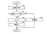
- FIG. 5 is a flowchart showing processing of ECU 160 when reflected power exceeding a threshold is detected in power supply facility 100 shown in FIG.
- ECU 160 receives, from power sensor 115, reflected power to power supply device 110 detected by power sensor 115 (FIG. 1) (step S10). Then, ECU 160 determines whether or not the detected value of reflected power is larger than a predetermined threshold value (step S20). This threshold value is appropriately set based on the specifications of the power supply device 110.
- ECU 160 turns on relay 190 (FIG. 1) (step S30). Thereby, the coil 180 (FIG. 1) is electrically connected to the electric path between the impedance matching device 120 and the primary coil 130, and the increased reflected power is emitted to the surrounding space by the emission self-resonant coil 185. ECU 160 then outputs an alarm to notify the surroundings that power is being discharged from the discharge coil unit (step S40).
- step S20 when it is determined in step S20 that the reflected power is equal to or less than the threshold value (NO in step S20), ECU 160 continues power transmission to vehicle 200 without turning on relay 190 (step S50).
- the discharge coil unit when the detected value of the reflected power exceeds a predetermined threshold value, the discharge coil unit is electrically connected between the power supply device 110 and the power transmission unit, The power output from the power supply device 110 is discharged to the outside by the discharge coil unit. Therefore, according to this embodiment, it is possible to prevent damage to power supply device 110 due to a sudden increase in reflected power.
- FIG. 6 is a flowchart showing the processing of the ECU 160 when the reflected power exceeding the threshold is detected in the power supply facility 100 according to this modification.
- this flowchart further includes step S35 in the flowchart shown in FIG. That is, when relay 190 is turned on in step S30, ECU 160 sets impedance matching unit 120 to a predetermined value for discharging (step S35).
- This predetermined value is a value obtained in advance so that the input impedance of the resonance system formed by the emission self-resonant coil 185 and the surrounding space matches the output impedance of the power supply device 110. Then, when the impedance of impedance matching unit 120 is changed to a predetermined value, ECU 160 proceeds to step S40 and an alarm is output.
- an excessive reflected power is emitted to the outside by providing the emission coil unit.
- a discharge resistor may be provided instead of the emission coil unit.
- FIG. 7 is an overall configuration diagram of a non-contact power feeding system in which a discharge resistor is provided instead of the discharge coil unit.
- this non-contact power feeding system includes power feeding facility 100 ⁇ / b> A and vehicle 200.
- Power supply facility 100 ⁇ / b> A includes a discharge resistor 195 instead of the discharge coil unit including coil 180 and discharge self-resonant coil 185 in the configuration of power supply facility 100 shown in FIG. 1.
- the relay 190 is turned on.
- the discharge resistor 195 is electrically connected to the electrical path between the impedance matching device 120 and the primary coil 130, and power is consumed in the discharge resistor 195, thereby suppressing a rapid increase in reflected power.
- the power transmission unit is composed of a pair of high dielectric disks. And a power receiving unit.
- the high dielectric disk is made of a high dielectric constant material, and for example, TiO 2 , BaTi 4 O 9 , LiTaO 3 or the like is used.
- secondary self-resonant coil 210, capacitor 220, and secondary coil 230 form one embodiment of the “power receiving unit” in the present invention
- primary coil 130, primary self-resonant coil 140, and capacitor 150 are An embodiment of a “power transmission unit” in the present invention is formed.
- the power sensor 115 corresponds to an embodiment of the “detection device” in the present invention
- the emission self-resonant coil 185 and the coil 180 form an embodiment of the “emission coil” in the present invention.
- relay 190 corresponds to an embodiment of “connection device” in the present invention
- shield box 420 corresponds to an embodiment of “electromagnetic shielding material” in the present invention
- impedance matching unit 120 corresponds to an embodiment of “impedance variable device” in the present invention
- ECU 160 corresponds to an embodiment of “control device” in the present invention.
Landscapes
- Engineering & Computer Science (AREA)
- Power Engineering (AREA)
- Computer Networks & Wireless Communication (AREA)
- Mechanical Engineering (AREA)
- Transportation (AREA)
- Sustainable Energy (AREA)
- Life Sciences & Earth Sciences (AREA)
- Sustainable Development (AREA)
- Signal Processing (AREA)
- Electromagnetism (AREA)
- Physics & Mathematics (AREA)
- Electric Propulsion And Braking For Vehicles (AREA)
- Charge And Discharge Circuits For Batteries Or The Like (AREA)
Abstract
Description
電源装置110への反射電力がしきい値よりも大きいと判定されたとき、リレー190をオンするとともに、放出用自己共振コイル185と周囲の空間とのインピーダンスが整合するようにインピーダンス整合器120のインピーダンスを変更してもよい。これにより、放出用コイルユニットの設計の自由度が向上する。
Claims (7)
- 受電ユニット(210,220,230)を含む受電装置(200)へ非接触で給電する非接触給電設備であって、
所定の周波数を有する電力を発生する電源装置(110)と、
前記電源装置から電力を受け、前記受電ユニットと電磁場を介して共鳴することにより前記受電ユニットへ非接触で送電するための送電ユニット(130,140,150)と、
前記電源装置への反射電力を検出するための検出装置(115)と、
前記電源装置から出力された電力を外部へ放出するための放出用コイル(180,185)と、
前記反射電力の検出値が予め定められた値を超えたとき、前記電源装置と前記送電ユニットとの間に前記放出用コイルを電気的に接続する接続装置(190)とを備える非接触給電設備。 - 前記放出用コイルの周囲に配設され、前記放出用コイルから外部へ電力を放出可能なように一方向のみが開口された電磁気遮蔽材(420)をさらに備え、
前記放出用コイルおよび前記電磁気遮蔽材は、地中に設けられ、
前記電磁気遮蔽材は、開口部が地中を向くように配設される、請求の範囲第1項に記載の非接触給電設備。 - 前記電源装置と前記送電ユニットとの間に設けられ、前記送電ユニットおよび前記受電ユニットによって構成される共鳴系の入力インピーダンスを調整するためのインピーダンス可変装置(120)をさらに備え、
前記接続装置は、前記反射電力の検出値が前記予め定められた値を超えたとき、前記インピーダンス可変装置と前記送電ユニットとの間に前記放出用コイルを電気的に接続する、請求の範囲第1項に記載の非接触給電設備。 - 前記反射電力の検出値が前記予め定められた値を超えたとき、前記接続装置を作動させるとともに、前記インピーダンス可変装置のインピーダンスを所定値に変更するための制御装置(160)をさらに備える、請求の範囲第3項に記載の非接触給電設備。
- 前記所定値は、前記放出用コイルとその周囲空間とのインピーダンスが整合するように予め設定された値である、請求の範囲第4項に記載の非接触給電設備。
- 前記送電ユニットは、
前記電源装置から電力を受ける一次コイル(130)と、
前記一次コイルから電磁誘導により給電され、前記電磁場を発生する一次自己共振コイル(140)とを含み、
前記受電ユニットは、
前記電磁場を介して前記一次自己共振コイルと共鳴することにより前記一次自己共振コイルから受電する二次自己共振コイル(210)と、
前記二次自己共振コイルによって受電された電力を電磁誘導により取出して出力する二次コイル(230)とを含む、請求の範囲第1項から第5項のいずれかに記載の非接触給電設備。 - 前記受電装置は、車両に搭載される、請求の範囲第1項から第5項のいずれかに記載の非接触給電設備。
Priority Applications (5)
| Application Number | Priority Date | Filing Date | Title |
|---|---|---|---|
| US13/580,518 US8581445B2 (en) | 2010-12-01 | 2010-12-01 | Wireless electric power feeding equipment |
| CN201080067100.6A CN103250325B (zh) | 2010-12-01 | 2010-12-01 | 非接触供电设备 |
| EP10860256.6A EP2530811B1 (en) | 2010-12-01 | 2010-12-01 | Wireless electric power feeding equipment |
| JP2012542280A JP5152446B2 (ja) | 2010-12-01 | 2010-12-01 | 非接触給電設備 |
| PCT/JP2010/071438 WO2012073348A1 (ja) | 2010-12-01 | 2010-12-01 | 非接触給電設備 |
Applications Claiming Priority (1)
| Application Number | Priority Date | Filing Date | Title |
|---|---|---|---|
| PCT/JP2010/071438 WO2012073348A1 (ja) | 2010-12-01 | 2010-12-01 | 非接触給電設備 |
Publications (1)
| Publication Number | Publication Date |
|---|---|
| WO2012073348A1 true WO2012073348A1 (ja) | 2012-06-07 |
Family
ID=46171333
Family Applications (1)
| Application Number | Title | Priority Date | Filing Date |
|---|---|---|---|
| PCT/JP2010/071438 Ceased WO2012073348A1 (ja) | 2010-12-01 | 2010-12-01 | 非接触給電設備 |
Country Status (5)
| Country | Link |
|---|---|
| US (1) | US8581445B2 (ja) |
| EP (1) | EP2530811B1 (ja) |
| JP (1) | JP5152446B2 (ja) |
| CN (1) | CN103250325B (ja) |
| WO (1) | WO2012073348A1 (ja) |
Cited By (6)
| Publication number | Priority date | Publication date | Assignee | Title |
|---|---|---|---|---|
| JP2013005615A (ja) * | 2011-06-17 | 2013-01-07 | Toyota Motor Corp | 受電装置、送電装置、車両、および非接触給電システム |
| CN102916500A (zh) * | 2012-10-24 | 2013-02-06 | 天津工业大学 | 一种多传感器的无线电能传输装置 |
| WO2014007352A1 (ja) * | 2012-07-05 | 2014-01-09 | 株式会社 豊田自動織機 | 送電機器及び非接触電力伝送装置 |
| JP2015520064A (ja) * | 2012-04-23 | 2015-07-16 | ボンバルディアー トランスポーテーション ゲゼルシャフト ミット ベシュレンクテル ハフツング | 陸上車両、特に鉄道車両または路面走行用自動車、への誘導による電気エネルギーの供給 |
| JP2018011481A (ja) * | 2016-07-15 | 2018-01-18 | 日本電業工作株式会社 | 無線充電装置および無線充電システム |
| JP2019004589A (ja) * | 2017-06-14 | 2019-01-10 | 矢崎総業株式会社 | シールド部材及び電力伝送ユニット |
Families Citing this family (14)
| Publication number | Priority date | Publication date | Assignee | Title |
|---|---|---|---|---|
| US8841881B2 (en) | 2010-06-02 | 2014-09-23 | Bryan Marc Failing | Energy transfer with vehicles |
| KR101222749B1 (ko) * | 2010-12-14 | 2013-01-16 | 삼성전기주식회사 | 무선 전력 전송 장치 및 그 전송 방법 |
| JP5802424B2 (ja) * | 2011-04-22 | 2015-10-28 | 矢崎総業株式会社 | 共鳴式非接触給電システム |
| JP5732307B2 (ja) * | 2011-04-22 | 2015-06-10 | 矢崎総業株式会社 | 共鳴式非接触給電システム |
| US8933589B2 (en) | 2012-02-07 | 2015-01-13 | The Gillette Company | Wireless power transfer using separately tunable resonators |
| US10038342B2 (en) * | 2013-05-15 | 2018-07-31 | Nec Corporation | Power transfer system with shielding body, power transmitting device with shielding body, and power transfer method for power transmitting system |
| JP6144176B2 (ja) * | 2013-10-15 | 2017-06-07 | 日東電工株式会社 | 磁界空間を形成可能な無線電力伝送装置及びその形成方法 |
| US9672976B2 (en) * | 2013-10-28 | 2017-06-06 | Nokia Corporation | Multi-mode wireless charging |
| US20150130290A1 (en) * | 2013-11-11 | 2015-05-14 | Samsung Electro-Mechanics Co., Ltd. | Wireless power transmitting apparatus and wireless power transmitting-receiving apparatus |
| US20160268846A1 (en) * | 2013-12-26 | 2016-09-15 | Mitsubishi Electric Engineering Company, Limited | Automatic matching circuit for high frequency power supply |
| EP3123486B1 (en) | 2014-03-26 | 2022-03-30 | Apple Inc. | Temperature management for inductive charging systems |
| US9780571B2 (en) | 2014-08-28 | 2017-10-03 | Motorola Solutions, Inc. | Methods and systems for providing a ballast load for a magnetic resonant power supply |
| JP2017131020A (ja) * | 2016-01-19 | 2017-07-27 | 株式会社ダイヘン | 非接触給電システムおよび受電装置 |
| KR102037876B1 (ko) * | 2017-10-27 | 2019-10-30 | 한국철도기술연구원 | 냉동컨테이너용 무선전력전송 구조 |
Citations (6)
| Publication number | Priority date | Publication date | Assignee | Title |
|---|---|---|---|---|
| WO2007008646A2 (en) | 2005-07-12 | 2007-01-18 | Massachusetts Institute Of Technology | Wireless non-radiative energy transfer |
| JP2010068634A (ja) | 2008-09-11 | 2010-03-25 | Yazaki Corp | 車両用ワイヤレス充電システム |
| WO2010035321A1 (ja) * | 2008-09-25 | 2010-04-01 | トヨタ自動車株式会社 | 給電システムおよび電動車両 |
| JP2010070048A (ja) | 2008-09-18 | 2010-04-02 | Toyota Motor Corp | 非接触受電装置、非接触送電装置、非接触給電システムおよび電動車両 |
| JP2010141976A (ja) * | 2008-12-09 | 2010-06-24 | Toyota Industries Corp | 非接触電力伝送装置 |
| JP2010154625A (ja) | 2008-12-24 | 2010-07-08 | Toyota Industries Corp | 共鳴型非接触充電装置 |
Family Cites Families (11)
| Publication number | Priority date | Publication date | Assignee | Title |
|---|---|---|---|---|
| GB2414120B (en) * | 2004-05-11 | 2008-04-02 | Splashpower Ltd | Controlling inductive power transfer systems |
| US7825543B2 (en) | 2005-07-12 | 2010-11-02 | Massachusetts Institute Of Technology | Wireless energy transfer |
| JP2007325388A (ja) * | 2006-05-31 | 2007-12-13 | Hitachi Ltd | 電動機の制御装置及び車載用電動機駆動システム |
| EP2130287A1 (en) | 2007-03-27 | 2009-12-09 | Massachusetts Institute of Technology | Wireless energy transfer |
| JPWO2009031639A1 (ja) * | 2007-09-06 | 2010-12-16 | 昭和電工株式会社 | 非接触充電式蓄電源装置 |
| JP4911148B2 (ja) * | 2008-09-02 | 2012-04-04 | ソニー株式会社 | 非接触給電装置 |
| MY160103A (en) * | 2008-10-03 | 2017-02-28 | Access Business Group Int Llc | Power system |
| CN102239622A (zh) | 2008-12-09 | 2011-11-09 | 株式会社丰田自动织机 | 非接触电力传输装置及非接触电力传输装置中的电力传输方法 |
| JP5238472B2 (ja) * | 2008-12-16 | 2013-07-17 | 株式会社日立製作所 | 電力伝送装置、および電力受信装置 |
| JP2010183812A (ja) * | 2009-02-09 | 2010-08-19 | Toyota Industries Corp | 共鳴型非接触充電システム |
| CN101572444B (zh) * | 2009-03-17 | 2011-06-15 | 苏州达方电子有限公司 | 无线能量传输系统、无线供电模块及能量供应方法 |
-
2010
- 2010-12-01 EP EP10860256.6A patent/EP2530811B1/en not_active Not-in-force
- 2010-12-01 US US13/580,518 patent/US8581445B2/en active Active
- 2010-12-01 JP JP2012542280A patent/JP5152446B2/ja not_active Expired - Fee Related
- 2010-12-01 WO PCT/JP2010/071438 patent/WO2012073348A1/ja not_active Ceased
- 2010-12-01 CN CN201080067100.6A patent/CN103250325B/zh not_active Expired - Fee Related
Patent Citations (6)
| Publication number | Priority date | Publication date | Assignee | Title |
|---|---|---|---|---|
| WO2007008646A2 (en) | 2005-07-12 | 2007-01-18 | Massachusetts Institute Of Technology | Wireless non-radiative energy transfer |
| JP2010068634A (ja) | 2008-09-11 | 2010-03-25 | Yazaki Corp | 車両用ワイヤレス充電システム |
| JP2010070048A (ja) | 2008-09-18 | 2010-04-02 | Toyota Motor Corp | 非接触受電装置、非接触送電装置、非接触給電システムおよび電動車両 |
| WO2010035321A1 (ja) * | 2008-09-25 | 2010-04-01 | トヨタ自動車株式会社 | 給電システムおよび電動車両 |
| JP2010141976A (ja) * | 2008-12-09 | 2010-06-24 | Toyota Industries Corp | 非接触電力伝送装置 |
| JP2010154625A (ja) | 2008-12-24 | 2010-07-08 | Toyota Industries Corp | 共鳴型非接触充電装置 |
Non-Patent Citations (1)
| Title |
|---|
| See also references of EP2530811A4 |
Cited By (7)
| Publication number | Priority date | Publication date | Assignee | Title |
|---|---|---|---|---|
| JP2013005615A (ja) * | 2011-06-17 | 2013-01-07 | Toyota Motor Corp | 受電装置、送電装置、車両、および非接触給電システム |
| JP2015520064A (ja) * | 2012-04-23 | 2015-07-16 | ボンバルディアー トランスポーテーション ゲゼルシャフト ミット ベシュレンクテル ハフツング | 陸上車両、特に鉄道車両または路面走行用自動車、への誘導による電気エネルギーの供給 |
| WO2014007352A1 (ja) * | 2012-07-05 | 2014-01-09 | 株式会社 豊田自動織機 | 送電機器及び非接触電力伝送装置 |
| CN102916500A (zh) * | 2012-10-24 | 2013-02-06 | 天津工业大学 | 一种多传感器的无线电能传输装置 |
| JP2018011481A (ja) * | 2016-07-15 | 2018-01-18 | 日本電業工作株式会社 | 無線充電装置および無線充電システム |
| JP2019004589A (ja) * | 2017-06-14 | 2019-01-10 | 矢崎総業株式会社 | シールド部材及び電力伝送ユニット |
| JP7043187B2 (ja) | 2017-06-14 | 2022-03-29 | 矢崎総業株式会社 | シールド部材及び電力伝送ユニット |
Also Published As
| Publication number | Publication date |
|---|---|
| EP2530811A4 (en) | 2014-05-07 |
| JPWO2012073348A1 (ja) | 2014-05-19 |
| US20130127242A1 (en) | 2013-05-23 |
| JP5152446B2 (ja) | 2013-02-27 |
| CN103250325B (zh) | 2015-04-08 |
| EP2530811A1 (en) | 2012-12-05 |
| EP2530811B1 (en) | 2016-07-13 |
| US8581445B2 (en) | 2013-11-12 |
| CN103250325A (zh) | 2013-08-14 |
Similar Documents
| Publication | Publication Date | Title |
|---|---|---|
| JP5152446B2 (ja) | 非接触給電設備 | |
| JP5287863B2 (ja) | 非接触受電装置およびそれを備える車両 | |
| JP4947241B2 (ja) | コイルユニット、非接触受電装置、非接触送電装置、非接触給電システムおよび車両 | |
| JP5703988B2 (ja) | 受電装置、送電装置、車両、および非接触給電システム | |
| EP2345553B1 (en) | Non-contact power transmission device and vehicle having non-contact power transmission device | |
| CN103270669B (zh) | 非接触供电系统、车辆、供电设备及非接触供电系统的控制方法 | |
| EP2576273B1 (en) | Power feeding system and vehicle | |
| US9536655B2 (en) | Wireless power feeding apparatus, vehicle, and method of controlling wireless power feeding system | |
| KR101634889B1 (ko) | 차량용 수전 장치 및 그것을 구비하는 차량, 급전 설비 및 전력 전송 시스템 | |
| US20110148351A1 (en) | Noncontact electric power receiving device, noncontact electric power transmitting device, noncontact electric power feeding system, and electrically powered vehicle | |
| WO2011099106A1 (en) | Electric power feed device for vehicle and electric power reception device | |
| JP2011166994A (ja) | 給電装置および車両給電システム | |
| JP2010074937A (ja) | 非接触受電装置およびそれを備える車両 | |
| JP2011066985A (ja) | 非接触受電装置およびそれを備える電動車両 | |
| JP5474470B2 (ja) | 非接触受電装置およびそれを備える電動車両 | |
| JP2010073885A (ja) | 共鳴コイルおよび非接触給電システム | |
| RU2461946C1 (ru) | Устройство бесконтактного получения энергии и транспортное средство, содержащее такое устройство | |
| JP2011166931A (ja) | 受電装置およびそれを備える車両 | |
| CN103522902A (zh) | 非接触受电装置及具有该非接触受电装置的车辆 |
Legal Events
| Date | Code | Title | Description |
|---|---|---|---|
| 121 | Ep: the epo has been informed by wipo that ep was designated in this application |
Ref document number: 10860256 Country of ref document: EP Kind code of ref document: A1 |
|
| WWE | Wipo information: entry into national phase |
Ref document number: 13580518 Country of ref document: US |
|
| REEP | Request for entry into the european phase |
Ref document number: 2010860256 Country of ref document: EP |
|
| WWE | Wipo information: entry into national phase |
Ref document number: 2010860256 Country of ref document: EP |
|
| WWE | Wipo information: entry into national phase |
Ref document number: 2012542280 Country of ref document: JP |
|
| NENP | Non-entry into the national phase |
Ref country code: DE |