WO2012073359A1 - 車両の操舵制御装置 - Google Patents
車両の操舵制御装置 Download PDFInfo
- Publication number
- WO2012073359A1 WO2012073359A1 PCT/JP2010/071512 JP2010071512W WO2012073359A1 WO 2012073359 A1 WO2012073359 A1 WO 2012073359A1 JP 2010071512 W JP2010071512 W JP 2010071512W WO 2012073359 A1 WO2012073359 A1 WO 2012073359A1
- Authority
- WO
- WIPO (PCT)
- Prior art keywords
- steering
- angle
- steering angle
- vehicle
- neutral point
- Prior art date
- Legal status (The legal status is an assumption and is not a legal conclusion. Google has not performed a legal analysis and makes no representation as to the accuracy of the status listed.)
- Ceased
Links
Images



Classifications
-
- B—PERFORMING OPERATIONS; TRANSPORTING
- B62—LAND VEHICLES FOR TRAVELLING OTHERWISE THAN ON RAILS
- B62D—MOTOR VEHICLES; TRAILERS
- B62D5/00—Power-assisted or power-driven steering
- B62D5/04—Power-assisted or power-driven steering electrical, e.g. using an electric servo-motor connected to, or forming part of, the steering gear
- B62D5/0457—Power-assisted or power-driven steering electrical, e.g. using an electric servo-motor connected to, or forming part of, the steering gear characterised by control features of the drive means as such
- B62D5/046—Controlling the motor
- B62D5/0466—Controlling the motor for returning the steering wheel to neutral position
-
- B—PERFORMING OPERATIONS; TRANSPORTING
- B62—LAND VEHICLES FOR TRAVELLING OTHERWISE THAN ON RAILS
- B62D—MOTOR VEHICLES; TRAILERS
- B62D15/00—Steering not otherwise provided for
- B62D15/02—Steering position indicators ; Steering position determination; Steering aids
- B62D15/021—Determination of steering angle
- B62D15/0245—Means or methods for determination of the central position of the steering system, e.g. straight ahead position
-
- B—PERFORMING OPERATIONS; TRANSPORTING
- B62—LAND VEHICLES FOR TRAVELLING OTHERWISE THAN ON RAILS
- B62D—MOTOR VEHICLES; TRAILERS
- B62D5/00—Power-assisted or power-driven steering
- B62D5/04—Power-assisted or power-driven steering electrical, e.g. using an electric servo-motor connected to, or forming part of, the steering gear
- B62D5/0457—Power-assisted or power-driven steering electrical, e.g. using an electric servo-motor connected to, or forming part of, the steering gear characterised by control features of the drive means as such
- B62D5/046—Controlling the motor
-
- B—PERFORMING OPERATIONS; TRANSPORTING
- B62—LAND VEHICLES FOR TRAVELLING OTHERWISE THAN ON RAILS
- B62D—MOTOR VEHICLES; TRAILERS
- B62D5/00—Power-assisted or power-driven steering
- B62D5/04—Power-assisted or power-driven steering electrical, e.g. using an electric servo-motor connected to, or forming part of, the steering gear
- B62D5/0457—Power-assisted or power-driven steering electrical, e.g. using an electric servo-motor connected to, or forming part of, the steering gear characterised by control features of the drive means as such
- B62D5/0481—Power-assisted or power-driven steering electrical, e.g. using an electric servo-motor connected to, or forming part of, the steering gear characterised by control features of the drive means as such monitoring the steering system, e.g. failures
-
- B—PERFORMING OPERATIONS; TRANSPORTING
- B62—LAND VEHICLES FOR TRAVELLING OTHERWISE THAN ON RAILS
- B62D—MOTOR VEHICLES; TRAILERS
- B62D5/00—Power-assisted or power-driven steering
- B62D5/04—Power-assisted or power-driven steering electrical, e.g. using an electric servo-motor connected to, or forming part of, the steering gear
- B62D5/0457—Power-assisted or power-driven steering electrical, e.g. using an electric servo-motor connected to, or forming part of, the steering gear characterised by control features of the drive means as such
- B62D5/0481—Power-assisted or power-driven steering electrical, e.g. using an electric servo-motor connected to, or forming part of, the steering gear characterised by control features of the drive means as such monitoring the steering system, e.g. failures
- B62D5/049—Power-assisted or power-driven steering electrical, e.g. using an electric servo-motor connected to, or forming part of, the steering gear characterised by control features of the drive means as such monitoring the steering system, e.g. failures detecting sensor failures
Definitions
- the present invention is, for example, VGRS (Variable Gear Ratio Steering), ARS (Active Rear Steering), AWS (All Wheel Steering) or SBW (Steer By Wire:
- the present invention relates to a technical field of a vehicle steering control device that controls a steering state of a vehicle equipped with various steering angle variable devices such as an electronically controlled steering angle variable device) that can change a steering angle independently of steering operation.
- Patent Document 1 a device that calculates the rudder angle midpoint has been proposed (for example, see Patent Document 1).
- the electric power steering device disclosed in Patent Document 1 since the straight traveling state of the vehicle can be accurately determined based on the steering wheel angle, the vehicle speed, and the axial force of the rack bar, the steering angle midpoint is deviated. Therefore, the control steering angle midpoint is accurately determined as a reference point for detecting the rotation angle of the steering shaft even in a state where the steering torque is applied so that the driver returns the steering wheel to the neutral position. It is supposed to be possible.
- Patent Document 2 discloses a technology for automatically driving a vehicle along a target locus, as an apparatus of this type is applicable.
- the rudder angle neutral point (based on the “steering angle midpoint” described above) calculated based on the detected value of the sensor. Corresponding) is significantly reduced in reliability.
- Steering angle neutral point is a reference point for steering angle and is a reference value for a wide range of vehicle motion control regardless of whether or not a steering angle variable device is used. In such a case, it is necessary to quickly relearn the steering wheel neutral point.
- Patent Document 1 As a condition and timing for re-learning the steering wheel angle neutral point, the control steering angle midpoint (that is, the steering wheel angle) stored when the power supply state from the battery is bad at the time of parking is described. There is a description to delete (neutral point).
- the present invention has been made in view of such problems, and an object of the present invention is to provide a vehicle steering control device capable of learning a steering angle neutral point with high accuracy.
- a vehicle steering control device is capable of changing a steering angle of a steering wheel including at least one of a front wheel and a rear wheel independently of a steering operation.
- a steering control device for a vehicle comprising: a steering angle equivalent value detecting means for detecting a steering angle equivalent value that gives an operation reference to the steering angle variable device corresponding to the steering angle.
- Learning means for learning, an abnormality determining means for determining whether or not the steering angle equivalent value detecting means is in an abnormal state, and when it is determined that the steering angle equivalent value detecting means is in the abnormal state,
- the rudder means for discarding the learned steering wheel angle neutral point and the rudder angle equivalent value detecting means when the rudder angle returns to the rudder angle neutral point when it is determined that the rudder angle equivalent value detecting means is in the abnormal state.
- Control hand to control the variable angle device And an initialization means for initializing the steering angle equivalent value detection means after the steering angle returns to the steering angle neutral point, and the learning means initializes the steering angle equivalent value detection means. After that, the learning of the handle angle is resumed.
- the steering angle varying device may suitably include, for example, VGRS if the front wheels are steering wheels, ARS if the rear wheels are steering wheels, and AWS if the four wheels are steering wheels.
- VGRS VGRS if the front wheels are steering wheels
- ARS ARS if the rear wheels are steering wheels
- AWS if the four wheels are steering wheels.
- the rudder angle can be changed independently of the steering wheel operation means that the rudder angle control in conjunction with the steering wheel operation (a unique rudder angle change by a mechanically connected steering mechanism is also considered as a steering wheel operation). Including appropriate steering angle assists) is not excluded.
- the rudder angle equivalent value according to the present invention corresponds to a rudder angle of a steered wheel on a one-to-one, one-to-many, many-to-one or many-to-many basis, or corresponds to a steered angle of a steered wheel uniquely or ambiguously. It means a physical quantity, control amount, or index value that gives an operation reference to the angle varying device, and preferably means a VGRS relative angle, an ARS relative angle, or the like that is paired with the steering angle varying device. Or you may mean the steering angle itself, for example. Note that “giving an operation reference” means providing a reference for the physical operation amount and physical operation state of the steering angle varying device.
- the vehicle steering control apparatus includes, for example, one or a plurality of CPUs (Central Processing Unit), MPU (Micro Processing Unit), various processors or various controllers, or ROM (Read Only Memory), RAM (Random Access). Memory), various storage units such as buffer memory or flash memory, etc., and various processing units such as a single or a plurality of ECUs (Electronic Controlled Units), various controllers or various computer systems such as microcomputer devices, etc. It can be taken.
- CPUs Central Processing Unit
- MPU Micro Processing Unit
- processors or various controllers or ROM (Read Only Memory), RAM (Random Access). Memory
- RAM Random Access
- Memory various storage units such as buffer memory or flash memory, etc.
- processing units such as a single or a plurality of ECUs (Electronic Controlled Units), various controllers or various computer systems such as microcomputer devices, etc. It can be taken.
- the steering angle neutral point is learned by the learning means.
- the steering wheel angle neutral point is a zero point of the steering wheel angle and means a steering wheel angle when the vehicle is maintained in a straight traveling state. That is, preferably, it is handled that the driver's aggressive steering operation (except for those similar to the steering holding operation) does not occur at the steering wheel neutral point.
- the learning means acquires a steering wheel angle when the vehicle is in a straight traveling state or is estimated to be in a straight traveling state as a sample value of a steering wheel neutral point (that is, a zero point), and is constant or indefinite. Learning by holding a predetermined number of the sample values obtained for each cycle, applying various arithmetic processing (including averaging and weighting) to the held sample values, and updating the handle angle neutral point May be performed. Even in a straight traveling state, as long as the driver holds the steering wheel, a considerable amount of steering wheel fluctuation can occur.
- the handle angle learning means may learn the handle angle neutral point as a certain range according to the occurrence of this kind of fluctuation.
- the rudder angle variable device is normally used as a standard for determining the rudder angle neutral point based on the rudder angle equivalent value detected by the rudder angle equivalent value detecting means and actually operating the rudder angle control.
- the steering angle neutral point means a value corresponding to the steering angle in a straight traveling state.
- the steering angle variable device is equivalent to, for example, a steering angle.
- the rudder angle equivalent value detection means can detect various abnormal states (detection values that exceed the normal range). Divergence, detection value is invalid value, value is not detected, output is not stable, or output may be hunted.
- detection value is invalid value, value is not detected, output is not stable, or output may be hunted.
- the rudder angle equivalent value detecting means is in an abnormal state, the reliability of the rudder angle neutral point is lowered to a level that is difficult to ignore in practice.
- the steering angle neutral point is lowered, the steering angle of the steered wheels is deflected to the left or right at the steering angle neutral point that should originally correspond to the straight traveling state, so that the vehicle deviates from the straight traveling state.
- the driver is likely to try to correct the vehicle to a straight traveling state by appropriately applying steering torque to the steering shaft by operating the steering wheel.
- the handle angle neutral point learned by the handle angle neutral point learning means described above deviates from the handle angle neutral point that should be originally.
- the learning value of the steering wheel neutral point is also less reliable.
- the presence or absence of such an abnormal state can be determined under various practical aspects according to the definition of the abnormal state, but simply because the steering angle equivalent value detection means is in the abnormal state, If the learning value is discarded and a new steering angle learning process is started, the abnormal state of the steering angle equivalent value detection means may affect the newly started steering angle neutral point learning process. Is difficult to eliminate. As a result, the learning accuracy of the steering angle neutral point that is re-learned decreases, and at least the time loss until a reliable steering angle neutral point is obtained and the deterioration of the quality of the steering control of the vehicle during that time cannot be ignored. May manifest to a degree.
- the control means when it is determined that the steering angle equivalent value detection means is in an abnormal state, the control means returns the steering angle of the steered wheels to the steering angle neutral point.
- the rudder angle varying device is controlled.
- the steering angle neutral point that is the control target of the control means is a steering angle neutral point that is not affected by the abnormal state related to the steering angle equivalent value detection means, for example, the initial position of the steering angle equivalent value detection means Means the rudder angle etc.
- the steering angle neutral point that is the control target of the control means is determined that the vehicle is in a straight traveling state by a determination process based on the yaw rate, the yaw deviation, the vehicle body slip angle, or the lateral acceleration of the vehicle.
- a practical steering angle position may be used. In any case, the vehicle is temporarily kept straight by the action of the control means.
- the steering angle equivalent value detection means is initialized by the initialization means.
- Initialization means that detection of the steering angle equivalent value is newly started with the detected value at that time as the zero point, that is, the steering angle neutral point.
- the learning means described above is configured to resume learning of the steering wheel angle neutral point after discarding the learning value of the steering wheel angle neutral point on condition that the initialization of the steering angle equivalent value detection means is completed. Has been.
- the steering angle neutral point learning process after the previous learning value is discarded can obtain a provisional straight-ahead state by the action of the control means. And the normal detection process of the steering angle equivalent value is resumed by the action of the initialization means. Therefore, the steering angle neutral point learning process is started under ideal conditions, and the steering angle neutral point can be learned quickly and with high accuracy.
- the vehicle further includes a neutral position detection unit that detects a neutral position of the steering angle equivalent value detection unit corresponding to the steering angle neutral point, The control means returns the rudder angle to the rudder angle neutral point based on the detected neutral position (claim 2).
- the neutral position of the steering angle equivalent value detection means detected by the neutral position detection means can be used.
- the processing relating to steering angle neutral point learning can be resumed.
- control means controls the steering angle varying device so that the steering angle returns to the steering angle neutral point within a predetermined time.
- the steering angle can be returned to the steering angle neutral point within a predetermined time when the abnormality determination of the steering angle equivalent value detecting means is performed. Therefore, as compared with the case where the steering angle is established and returned to the steering angle neutral point, the time variation of a series of return processing at the time of abnormality determination of the steering angle equivalent value detection means is suppressed, and the quality is improved. .
- the “predetermined time” means that the learning value of the handle angle neutral position is derived from the predetermined time as a legal restriction by the handle angle neutral point learning process. It may be a grace time that is obtained by reducing the time required to complete the process.
- a change speed of the steering angle when the steering angle is returned to the steering angle neutral point is determined based on at least one of a steering operation speed and a vehicle speed.
- the control means further includes a determining means, and the control means controls the steering angle varying device so that the steering angle changes at the determined change speed.
- the rudder angle control toward the rudder angle neutral point related to the control means is a kind of compulsory control and is essentially irrelevant to the driver's intention and sensitivity. Therefore, depending on the situation, there may be a situation in which the driver feels uncomfortable or uncomfortable.
- control means sets the steering angle to the steering angle neutral point based on at least one of the steering wheel operation speed (for example, the time differential value of the steering wheel angle detected by the steering wheel angle sensor) and the vehicle speed.
- the speed of change of the rudder angle when controlling toward is limited.
- the change speed of the steering angle is set relatively large. Can do. Further, in a situation where the vehicle speed is relatively high, the influence of the change in the steering angle on the vehicle behavior becomes relatively large. Therefore, it is preferable that the change speed of the steering angle is relatively small. Note that the change speed of the rudder angle can be returned to the rudder angle neutral point as quickly as possible within a range that does not cause the driver to feel uncomfortable or uncomfortable experimentally, empirically, or theoretically in advance. It may be set as follows.
- an automatic steering control means for controlling the steering angle varying device so that the vehicle is in an automatic steering state based on a preset driving condition, and the vehicle And a rectilinear determining means for determining whether or not the vehicle is in a straight traveling state, wherein the discarding means is configured so that the steering angle equivalent value detecting means is in the abnormal state during an automatic steering period in which the vehicle is in the automatic steering state. If it is determined that the vehicle is in the straight traveling state, the learned steering wheel angle neutral point is discarded when the vehicle is determined to be in the straight traveling state, and the control means is configured so that the vehicle is in the automatic steering state. When the steering angle equivalent value detecting means is determined to be in the abnormal state during the automatic steering period, the steering angle is converted to the steering angle when it is determined that the vehicle is in the straight traveling state. Neutral point Causes attributed (claim 5).
- the vehicle shifts to the automatic steering state based on the driving condition set in advance by the automatic steering control means.
- the automatic steering state means a traveling state that does not require the driver's aggressive steering operation.
- the control of the rudder angle varying device for this kind of automatic steering state by the automatic steering control means may be control that causes the vehicle to trace the target travel path, such as LKA (Lane Keeping Assist).
- the automatic steering control means includes a white line that defines a target travel path, Invite the vehicle to the automatic steering state by changing the control amount of the steering angle varying device according to the position state deviation (for example, lateral position deviation, yaw angle deviation, etc.) that defines the positional relationship between the lane mark and the vehicle body Also good.
- the position state deviation for example, lateral position deviation, yaw angle deviation, etc.
- the driver does not have a positive intention to steer, and the vehicle state is not limited to the straight traveling state but may be in a turning state. Therefore, when the abnormality determination of the steering angle equivalent value detection means is established during the automatic steering period in which the vehicle is in the automatic steering state, the steering angle is returned to the steering angle neutral point by the action of the control means. The vehicle behavior is greatly affected. Of course, at the same time, an increase in the psychological burden on the driver, an uncomfortable feeling, anxiety, or discomfort may occur.
- the straight traveling determination means determines that the vehicle is in a straight traveling state
- the learning value of the steering wheel neutral point is discarded and the control of the steering angle by the control means is permitted. Is done. Therefore, destabilization of the vehicle behavior and discomfort, anxiety or discomfort to the driver are prevented, and high-quality steering control is provided.
- the straight-ahead determination relating to the straight-ahead determination means can be made relatively simple, for example, by comparing the yaw rate and the threshold value, but the vehicle state that can be determined as the straight-ahead state by the straight-ahead determination is the steering angle related to the control means. It does not necessarily coincide with the straight traveling state obtained by the steering angle control to the neutral point. More specifically, as long as the above-mentioned various problems do not become apparent when the rudder angle is returned to the rudder angle neutral point by the control unit, the straight-running state determined as the straight-running state by the straight-running determination unit is relatively It may include a turning state on a small scale.
- FIG. 1 is a schematic configuration diagram conceptually showing a configuration of a steering system in a vehicle according to a first embodiment of the present invention.
- FIG. 2 is a block diagram related to steering control in the vehicle of FIG. 1.
- 2 is a flowchart of steering angle neutral position control executed by an ECU in the vehicle of FIG. 1. It is a flowchart of the ACT sensor abnormal state value update process relevant to the control of FIG. It is a flowchart of steering wheel angle neutral position control in 2nd Embodiment of this invention.
- FIG. 1 is a schematic configuration diagram conceptually showing the configuration of the steering system in the vehicle 10.
- a vehicle 10 includes a pair of left and right front wheels FL and FR and a pair of left and right rear wheels RL and RR as steering wheels, and these steered wheels are steered in the left and right directions so that they can travel in a desired direction. It is configured.
- the vehicle 10 includes an ECU 100, a VGRS actuator 200, a VGRS driving device 300, an EPS actuator 400, an EPS driving device 500, an ARS actuator 600, and an ARS driving device 700.
- the ECU 100 is an electronic control unit that includes a CPU (Central Processing Unit), a ROM (Read Only Memory), and a RAM (Random Access Memory) (not shown), and is configured to be able to control the entire operation of the vehicle 10. 1 is an example of a “vehicle steering control device”.
- the ECU 100 is configured to execute steering wheel angle neutral point control, which will be described later, according to a control program stored in the ROM.
- the ECU 100 is an integrated electronic control unit configured to function as an example of each of “learning means”, “abnormality determination means”, “discard means”, “control means”, and “initialization means” according to the present invention. Thus, all the operations related to these means are configured to be executed by the ECU 100.
- the physical, mechanical, and electrical configurations of each of the units according to the present invention are not limited to this.
- each of these units includes a plurality of ECUs, various processing units, various controllers, a microcomputer device, and the like. It may be configured as various computer systems.
- a steering input given from a driver via a handle 11 as a steering input means is connected to the handle 11 so as to be coaxially rotatable, and is connected to an upper steering shaft 12 that is a shaft body that can rotate in the same direction as the handle 11. Communicated.
- the upper steering shaft 12 is connected to the VGRS actuator 200 at its downstream end.
- the VGRS actuator 200 is an example of a “steering angle varying device” according to the present invention, which includes a housing 201, a VGRS motor 202, and a speed reduction mechanism 203.
- the housing 201 is a housing of the VGRS actuator 200 that houses the VGRS motor 202 and the speed reduction mechanism 203.
- the downstream end of the above-described upper steering shaft 12 is fixed to the housing 201, and the housing 201 can rotate integrally with the upper steering shaft 12.
- the VGRS motor 202 is a DC brushless motor having a rotor 202a serving as a rotor, a stator 202b serving as a stator, and a rotating shaft 202c serving as an output shaft for driving force.
- the stator 202b is fixed inside the housing 201, and the rotor 202a is rotatably held inside the housing 201.
- the rotating shaft 202c is fixed so as to be coaxially rotatable with the rotor 202a, and its downstream end is connected to the speed reduction mechanism 203.
- the speed reduction mechanism 203 is a planetary gear mechanism having a plurality of rotating elements (sun gear, carrier and ring gear) capable of differential rotation.
- the sun gear that is the first rotating element is connected to the rotating shaft 202 c of the VGRS motor 202, and the carrier that is the second rotating element is connected to the housing 201.
- a ring gear as a third rotating element is connected to the lower steering shaft 13.
- the rotational speed of the upper steering shaft 12 (that is, the rotational speed of the housing 201 connected to the carrier) corresponding to the operation amount of the handle 11 and the rotational speed of the VGRS motor 202 (That is, the rotational speed of the rotary shaft 202c connected to the sun gear) uniquely determines the rotational speed of the lower steering shaft 13 connected to the ring gear that is the remaining one rotational element.
- the rotational speed of the lower steering shaft 13 can be controlled to increase / decrease by controlling the rotational speed of the VGRS motor 202 to increase / decrease by the differential action between the rotating elements.
- the upper steering shaft 12 and the lower steering shaft 13 can be rotated relative to each other by the action of the VGRS motor 202 and the speed reduction mechanism 203. Further, due to the configuration of each rotary element in the speed reduction mechanism 203, the rotation speed of the VGRS motor 202 is transmitted to the lower steering shaft 13 in a state where the speed is reduced according to a predetermined reduction ratio determined according to the gear ratio between the respective rotary elements.
- the upper steering shaft 12 and the lower steering shaft 13 can rotate relative to each other, so that the steering angle ⁇ h that is the rotation amount of the upper steering shaft 12 and the rotation amount of the lower steering shaft 13 are determined.
- the steering transmission ratio K which is uniquely determined (which also relates to the gear ratio of the rack and pinion mechanism described later) and the steering angle ⁇ f of the front wheel which is a steered wheel, is continuously variable within a predetermined range. .
- the VGRS actuator 200 can change the relationship between the steering wheel angle ⁇ h and the steering angle ⁇ f, and can change the steering angle ⁇ f of the front wheels regardless of the steering input of the driver.
- the speed reduction mechanism 203 is not limited to the planetary gear mechanism exemplified here, but is connected to other modes (for example, the upper steering shaft 12 and the lower steering shaft 13 are connected to gears having different numbers of teeth and partially contact each gear.
- the planetary gear mechanism may have a physical, mechanical, or mechanical aspect different from the above.
- the VGRS drive device 300 is an electric drive circuit including a PWM circuit, a transistor circuit, an inverter, and the like that are configured to be energized with respect to the stator 202b of the VGRS motor 202.
- the VGRS driving device 300 is electrically connected to a battery (not shown), and is configured to be able to supply a driving voltage to the VGRS motor 202 with electric power supplied from the battery. Further, the VGRS driving device 300 is electrically connected to the ECU 100, and its operation is controlled by the ECU 100.
- the VGRS driving device 300 and the VGRS actuator 200 constitute an example of the “steering angle varying device” according to the present invention.
- the steering mechanism 14 is a so-called rack and pinion mechanism, and includes a pinion gear 14A connected to the downstream end of the lower steering shaft 13 and a rack bar 14B formed with gear teeth that mesh with gear teeth of the pinion gear. Mechanism.
- the steering mechanism 14 converts the rotation of the pinion gear 14A into a horizontal movement of the rack bar 14B in the figure, whereby a steering force is transmitted via tie rods and knuckles (not shown) connected to both ends of the rack bar 14B. Is transmitted to each front wheel.
- the EPS actuator 400 is a steering torque assisting device including an EPS motor as a DC brushless motor including a rotor (not shown) as a rotor to which a permanent magnet is attached and a stator that is a stator surrounding the rotor.
- This EPS motor is configured to be capable of generating an assist torque TA in the rotation direction when the rotor is rotated by the action of a rotating magnetic field formed in the EPS motor by energizing the stator via the EPS driving device 500. ing.
- a reduction gear (not shown) is fixed to the motor shaft which is the rotation shaft of the EPS motor, and this reduction gear is also meshed with the pinion gear 14A.
- the assist torque TA generated from the EPS motor functions as an assist torque that assists the rotation of the pinion gear 14A.
- the pinion gear 14 ⁇ / b> A is connected to the lower steering shaft 13 as described above, and the lower steering shaft 13 is connected to the upper steering shaft 12 via the VGRS actuator 200. Therefore, the steering torque MT applied to the upper steering shaft 12 is transmitted to the rack bar 14B in a form that is appropriately assisted by the assist torque TA, thereby reducing the driver's steering burden.
- the EPS drive device 500 is an electric drive circuit including a PWM circuit, a transistor circuit, an inverter, and the like that are configured to be energized to the stator of the EPS motor.
- the EPS driving device 500 is electrically connected to a battery (not shown), and is configured to be able to supply a driving voltage to the EPS motor with electric power supplied from the battery. Further, the EPS driving device 500 is electrically connected to the ECU 100, and its operation is controlled by the ECU 100.
- the vehicle 10 is provided with various sensors including a steering torque sensor 15, a handle angle sensor 16, and a VGRS rotation angle sensor 17.
- the steering torque sensor 15 is a sensor configured to be able to detect the steering torque MT given from the driver via the handle 11. More specifically, the upper steering shaft 12 is divided into an upstream portion and a downstream portion, and has a configuration in which they are connected to each other by a torsion bar (not shown). Rings for detecting a rotational phase difference are fixed to both upstream and downstream ends of the torsion bar. The torsion bar is twisted in the rotational direction in accordance with a steering torque (that is, steering torque MT) transmitted through the upstream portion of the upper steering shaft 12 when the driver of the vehicle 10 operates the handle 11. Thus, the steering torque can be transmitted to the downstream portion while causing such a twist.
- a steering torque that is, steering torque MT
- the steering torque sensor 15 is configured to detect such a rotational phase difference and to convert the rotational phase difference into a steering torque and output it as an electrical signal corresponding to the steering torque MT. Further, the steering torque sensor 15 is electrically connected to the ECU 100, and the detected steering torque MT is referred to by the ECU 100 at a constant or indefinite period.
- the handle angle sensor 16 is an angle sensor configured to be able to detect a handle angle ⁇ h representing the amount of rotation of the upper steering shaft 12.
- the handle angle sensor 16 is electrically connected to the ECU 100, and the detected handle angle ⁇ h is referred to by the ECU 100 at a constant or indefinite period.
- the VGRS rotation angle sensor 17 can detect a VGRS rotation angle ⁇ vgrs that is a relative rotation angle between the housing 201 (that is, equivalent to the upper steering shaft 12 in terms of rotation angle) and the lower steering shaft 13 in the VGRS actuator 200. It is a configured rotary encoder.
- the VGRS rotation angle sensor 17 is electrically connected to the ECU 100, and the detected VGRS rotation angle ⁇ vgrs is referenced by the ECU 100 at a constant or indefinite period.
- the VGRS rotation angle ⁇ vgrs detected by the VGRS rotation angle sensor 17 has a one-to-one correspondence with the front wheel steering angle ⁇ f by adding the steering wheel angle ⁇ h.
- the VGRS rotation angle ⁇ vgrs is an example of the “steering angle equivalent value” according to the present invention
- the VGRS rotation angle sensor 17 is an example of the “steering angle equivalent value detecting unit” according to the present invention.
- the vehicle 10 further includes a vehicle speed sensor 18 and a yaw rate sensor 19.
- the vehicle speed sensor 18 is a sensor configured to be able to detect the vehicle speed V that is the speed of the vehicle 10.
- the vehicle speed sensor 18 is electrically connected to the ECU 100, and the detected vehicle speed V is referred to by the ECU 100 at a constant or indefinite period.
- the yaw rate sensor 19 is a sensor configured to be able to detect the yaw rate ⁇ as the turning speed of the vehicle 10.
- the yaw rate sensor 19 is electrically connected to the ECU 100, and the detected yaw rate ⁇ is referred to by the ECU 100 at a constant or indefinite period.
- the ARS actuator 600 is a rear wheel steering angle varying device including a steering angle control rod (not shown), an ARS motor, and a linear motion mechanism that converts the rotation of the ARS motor into a reciprocating motion of the steering angle control rod. It is an example of the “steering angle varying device” according to the present invention.
- the rear wheels RL and RR are connected to both ends of the rudder angle control rod via a support such as a knuckle, and the rudder angle control rod is either left or right by the driving force applied from the ARS motor.
- the rear wheel steering angle ⁇ r changes according to the stroke amount.
- the ARS drive device 700 is an electric drive circuit including a PWM circuit, a transistor circuit, an inverter, and the like configured to be able to energize the ARS motor.
- the ARS driving device 700 is electrically connected to a battery (not shown), and is configured to be able to supply a driving voltage to the ARS motor with electric power supplied from the battery.
- the ARS driving device 700 is electrically connected to the ECU 100, and its operation is controlled by the ECU 100.
- the vehicle 10 is provided with an ARS rotation angle sensor 20.
- This is a rotary encoder configured to be able to detect an ARS rotation angle ⁇ ars which is a rotation angle of an ARS motor housed in the ARS actuator 600.
- the ARS rotation angle sensor 20 is electrically connected to the ECU 100, and the detected ARS rotation angle ⁇ ars is referred to by the ECU 100 at a constant or indefinite period.
- the ARS rotation angle ⁇ ars detected by the ARS rotation angle sensor 20 has a one-to-one correspondence with the rear wheel steering angle ⁇ r. That is, the ARS rotation angle ⁇ ars is an example of the “steering angle equivalent value” according to the present invention, and the ARS rotation angle sensor 20 is another example of the “steering angle equivalent value detecting unit” according to the present invention.
- FIG. 2 is a block diagram relating to the steering control of the vehicle 10.
- the same reference numerals are given to the same portions as those in FIG. 1, and the description will be omitted as appropriate.
- the ECU 100 includes a steering wheel control unit 100A, a steering wheel angle neutral point learning unit 100B, and a correction unit 100C.
- Steering wheel control unit 100A is a device that calculates control amounts of front wheels and rear wheels that are steering wheels.
- the VGRS rotation angle ⁇ vgrs, the vehicle speed V, the ARS rotation angle ⁇ ars, and a correction handle angle ⁇ h_cr described later are input to the steering wheel control unit 100A as input values.
- the steered wheel control unit 100A selects a target VGRS rotation angle ⁇ vgrstg and a target ARS rotation angle ⁇ arstg corresponding to these input values from the VGRS rotation angle map and the ARS rotation angle map stored in advance in the ROM, and outputs them as output values. It is the composition to output.
- the target VGRS rotation angle ⁇ vgrstg is calculated as a deviation with respect to the current VGRS rotation angle ⁇ vgrs and input to the VGRS driving device 300.
- a deviation from the target ARS rotation angle ⁇ ars and the current ARS rotation angle ⁇ ars is calculated and input to the ARS drive device 700.
- the handle angle neutral point learning unit 100B is a device that learns the handle angle neutral point ⁇ h_zero which is the neutral position of the handle angle ⁇ h.
- VGRS rotation angle ⁇ vgrs, ARS rotation angle ⁇ ars, vehicle speed V, handle angle ⁇ h, yaw rate ⁇ , and handle angle neutral point ⁇ h_zero are input to the handle angle neutral point learning unit 100B.
- the steering wheel angle neutral point learning unit 100B is configured to always calculate the latest steering wheel neutral point ⁇ h_zero from these input values according to a preset learning algorithm when the vehicle 10 is in a straight traveling state. It should be noted that various known modes can be applied to the steering angle neutral point learning process, and therefore detailed description thereof will be omitted here.
- the correction unit 100C is a device that calculates a corrected handle angle ⁇ h_cr, which is a net handle operation amount based on the driver's steering intention, by subtracting the handle angle neutral point ⁇ h_zero from the handle angle ⁇ h.
- the steered wheel control unit 100A is configured to control the steering angles of the front and rear wheels based on the corrected handle angle ⁇ h_cr.
- the handle angle neutral point control is a control for maintaining the handle angle neutral point ⁇ h_zero with high accuracy.
- the steering wheel neutral point ⁇ h_zero is a reference value for calculating a corrected steering wheel angle ⁇ h_cr, which is one of the input values of the steering wheel controller 100A that controls the steering angle of the actual front and rear wheels. Become. Therefore, when the accuracy of the steering wheel angle neutral point ⁇ h_zero is insufficient, the steering wheel control unit 100A cannot accurately control the front and rear wheels. This is especially true when the steering wheel neutral point ⁇ h_zero is an abnormal value.
- the steering wheel neutral point ⁇ h_zero is affected by the accuracy of the steering angle control of the front and rear wheels toward the steering angle neutral point.
- the steering angle neutral point is the steering angle when the vehicle is traveling straight.
- the handle 11 is supposed to be maintained in a steered state.
- the detection accuracy of the VGRS rotation angle ⁇ vgrs and the ARS rotation angle ⁇ ars is lowered. If this is the case, the steered wheels will not stop at the original steering angle neutral point. For this reason, the driver who desires the straight traveling extends to the act of correcting the steering angle by giving the steering torque via the handle 11.
- the steering wheel angle neutral point ⁇ h_zero is a steering wheel angle when the vehicle is traveling straight, so even if the vehicle 10 is traveling straight as a result of correcting the steering angle by applying steering torque in this way, May be learned as a handle angle neutral point ⁇ h_zero.
- the vehicle 10 in a state where the driver holds the steering wheel 11, the vehicle 10 is deflected in either the left or right direction, which is very undesirable in controlling the behavior of the vehicle. That is, in order to maintain the accuracy of the handle angle neutral point ⁇ h_zero, it is necessary to appropriately deal with the abnormal state of the VGRS rotation angle sensor 17 and the ARS rotation angle sensor 20.
- the handle angle neutral point ⁇ h_zero is maintained with high accuracy by the handle angle neutral point control.
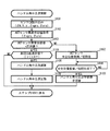
- FIG. 3 is a flowchart of the handle angle neutral point control.
- the ECU 100 is configured by each device illustrated in FIG. 2, but here, unless otherwise specified, the operation of the ECU 100 is described without regard to each device.
- the vehicle 10 includes the VGRS rotation angle sensor 17 and the ARS rotation angle sensor 20 as “steering angle equivalent value detection means” according to the present invention, but here, from the meaning of a sensor attached to each actuator, as appropriate.
- the term “ACT sensor” is used to express it comprehensively.
- the ECU 100 reads sensor values detected by various sensors (step S101). More specifically, the ECU 100 reads the steering wheel angle ⁇ h, the vehicle speed V, the yaw rate ⁇ , the VGRS rotation angle ⁇ vgrs and the ARS rotation angle ⁇ ars.
- the ECU 100 acquires an ACT sensor abnormal state value that defines whether the ACT sensor is in an abnormal state or a normal state (step S102).
- the ACT sensor abnormal state value is either “normal value” meaning that the ACT sensor is in a normal state or “abnormal value” meaning that the ACT sensor is in an abnormal state. It is set by an ACT sensor abnormal state value update process executed in parallel with the point control.
- FIG. 4 is a flowchart of the ACT sensor abnormal state value determination process.
- the ECU 100 determines whether or not the ACT sensor is in a normal state (step S201).
- the “normal state” means a state in which the detection value of the ACT sensor is ensured with a certain level of reliability. Whether or not the ACT sensor is in a normal state is determined by comprehensively considering the operating state of the ACT sensor. More specifically, when the detected value of the ACT sensor exceeds the appropriate range, is diverging, is an invalid value, is not detected, the output is not stable, or hunting is taken, It is determined that the ACT sensor is in an abnormal state. In addition, it is not restricted to what is illustrated here, The criterion which can make the determination that the reliability of an ACT sensor is not ensured experimentally, empirically, or theoretically may be given beforehand.
- step S202 When the ACT sensor is in an abnormal state (step S202: NO), the ECU 100 sets the ACT sensor abnormal state value to “abnormal value” (step S206). When step S206 is executed, the process returns to step S201.
- step S201 when the ACT sensor is in a normal state (step S201: YES), the ECU 100 determines whether or not the current ACT sensor abnormal state value is a “normal value” (step S202). If the current ACT sensor abnormal state value is “normal value” (step S202: YES), the ECU 100 sets the ACT sensor abnormal state to a normal value (step S203). When step S203 is executed, the process returns to step S201.
- step S202 when the ACT sensor abnormal state value at the present time (the ACT sensor is in a normal state) is “abnormal value” (step S202: NO), the ECU 100 returns the ACT sensor to the neutral position described later and the initial state. It is determined whether or not conversion is completed (step S204). When the return to the neutral position and the initialization have not been completed yet (step S204: NO), the ECU 100 shifts the process to step S206. That is, the ACT sensor abnormal state value is maintained as “abnormal value”.
- step S204 when the return to the neutral position of the ACT sensor and initialization have been completed (step S204: YES), the ECU 100 proceeds to step S203 and sets the ACT sensor abnormal state value to “normal value”. Switch.
- the ACT sensor abnormal state value update process is executed as described above.
- the ECU 100 determines whether or not the ACT sensor abnormal state value is “normal value” (step S103).
- the ECU 100 determines whether or not the vehicle 10 is in a straight traveling state (step S104). Whether or not the vehicle is in the straight traveling state is determined by whether or not the absolute value of the yaw rate ⁇ (the yaw rate ⁇ takes a positive or negative value depending on the turning direction) is less than the reference value A. When the yaw rate ⁇ is less than the reference value A, it is determined that the vehicle 10 is in a straight traveling state.
- step S104 When it is determined that the vehicle 10 is in the straight traveling state (step S104: YES), the ECU 100 calculates the steering wheel angle neutral point ⁇ h_zero according to a preset learning algorithm (step S105). The steering wheel angle neutral point ⁇ h_zero obtained as a result of the calculation is updated as the latest learning value (step S106). When the latest learning value of the handle angle neutral point ⁇ h_zero is obtained, the process returns to step S101. In Step S104, when it is determined that the vehicle 10 is not in the straight traveling state (Step S104: NO), the process is returned to Step S101. That is, in this case, the steering wheel angle neutral point ⁇ h_zero is maintained at the previous value without being learned.
- step S103 when the ACT sensor abnormal state value is “abnormal value” in step S103 (step S103: NO), the ECU 100 returns the ACT sensor to the neutral position and initializes it (step S107).
- the “neutral position” relating to the ACT sensor is a reference neutral position set in advance in the ACT sensor and is not necessarily a position corresponding to the steering angle neutral point of the vehicle 10, but at the time of initial setting. Since the entire steering apparatus is constructed so that the vehicle 10 is in the straight traveling state at the neutral position, by driving the actuator corresponding to the ACT sensor in the abnormal state so that the ACT sensor is in the neutral position, The corresponding rudder angle is also returned to the reference neutral position.
- “initialization” related to the ACT sensor is a reset process for canceling the abnormal state. Note that when the ACT sensor is physically damaged, mechanically or electrically damaged to such an extent that its performance cannot be fully exhibited, such initialization is hardly meaningful. In this case, the warning light provided to the vehicle 10 is quickly turned on.
- the abnormality targeted in this embodiment is mainly an abnormality that temporarily occurs for some reason.
- the ECU 100 determines whether or not the steering angle corresponding to the ACT sensor in the abnormal state has returned to the neutral position (that is, the ACT sensor is uniquely at the neutral position) and the initialization of the ACT sensor has been completed. (Step S108).
- the process according to step S108 is equivalent to the process according to step S204 of the ACT sensor abnormal state value update process of FIG.
- step S108: NO the process is temporarily maintained in a standby state.
- step S108 When the return to the neutral position of the steering angle and the initialization of the ACT sensor are completed (step S108: YES), that is, when the vehicle 10 temporarily goes straight and the ACT sensor starts to function normally, the ECU 100 Then, the learning value of the handle angle neutral point ⁇ h_zero held at that time is discarded (step S109). When the learning value is discarded, the process returns to step S101.
- the steering wheel angle neutral point control proceeds as described above.
- step S108 branches to the “YES” side
- the ACT sensor abnormal state value is switched to “normal value”. Therefore, the determination relating to step S103 that comes after the steering wheel neutral point ⁇ h_zero is discarded is “YES”. Branch to the side. Further, since the return to the neutral position of the rudder angle has already been completed, the vehicle 10 is temporarily maintained in the straight traveling state, and the determination relating to step S104 also branches to the “YES” side.
- the steering angle neutral point ⁇ h_zero consisting of steps S105 and S106 is quickly executed.
- the initialization of the ACT sensor has already been completed, and the abnormal detected value output from the ACT sensor in the abnormal state does not affect the steering wheel neutral point learning process.
- a transient error during returning from an abnormal state does not affect the handle angle neutral point learning process.
- the steering angle neutral point ⁇ h_zero can be learned quickly and accurately in terms of term when determining the abnormality of the ACT sensor.
- step S107 when the steering angle is returned to the neutral position based on the neutral position of the ACT sensor, the change speed of the steering angle is set to the steering wheel angular speed ⁇ h ′ which is the changing speed of the steering wheel angle ⁇ h at that time or the vehicle speed V. It may be changed in multiple stages according to the above. For example, the change speed of the steering angle may be changed to a large or small value with respect to the change in the steering wheel angular speed ⁇ h ′. Alternatively, the change speed of the rudder angle may be changed to small or large with respect to the vehicle speed V. Thus, by changing the change speed of the rudder angle according to the traveling state or steering state of the vehicle 10 at that time, it is possible to prevent the driver from feeling uncomfortable, uneasy or uncomfortable.
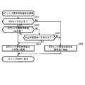
- FIG. 5 is a flowchart of the handle angle neutral point control.
- the same reference numerals are given to the same portions as those in FIG. 3, and the description thereof will be omitted as appropriate.
- the steering wheel neutral point control according to the second embodiment is control for the vehicle 10 that can take an automatic running state.
- various known aspects can be applied to practical aspects of automatic driving, and details thereof will be omitted here.
- locus tracking control such as LKA is executed. Good.
- the target of the lateral acceleration generated in the vehicle body based on the yaw angle deviation between the white line or lane mark captured by the vehicle-mounted camera or the like, the radius (or curvature) of the travel path, the yaw rate, etc.
- the operation of various actuators such as the VGRS actuator 300 and the ARS actuator 700 may be controlled so that a value is determined and a lateral acceleration corresponding to the determined target value is obtained. Further, in realizing such an automatic running state, steering torque assistance by a steering torque assisting device such as an EPS actuator may be appropriately accompanied.
- step S103 when the abnormal state value of the ACT sensor is “abnormal value” (step S103: NO), the ECU 100 determines whether or not the vehicle 10 is running automatically (step S301). When the vehicle 10 is not automatically traveling (step S301: NO), the process proceeds to step S107, and the process proceeds as in the first embodiment.
- step S301 when the vehicle 10 is traveling automatically (step S301: YES), the ECU 100 determines whether or not the vehicle 10 is traveling straight ahead (step S302). If the vehicle 10 is not turning straight, such as when the vehicle 10 is turning in the course of automatic traveling control (step S302: NO), the process returns to step S301. That is, in this case, the return to the neutral position of the ACT sensor and the initialization are temporarily in a standby state.
- step S302 If the vehicle 10 is traveling straight ahead in step S302 (step S302: YES), the ECU 100 forcibly terminates automatic traveling (step S303), and the process proceeds to step S107.
- the handle angle neutral point control according to the second embodiment, when the vehicle 10 is under various automatic travel controls such as LKA, the steering is waited for the vehicle 10 to go straight. The corner is returned to the neutral position. Therefore, in the automatic steering period in which the driver does not intend to steer, the vehicle 10 that is turning is suddenly returned to the straight traveling state, thereby destabilizing the vehicle behavior and causing the driver to feel uncomfortable, uneasy and uncomfortable. The generation
- the “straight running” according to step S302 may be a straight running state that is less rigorous than a straight running state obtained when the rudder angle is in the neutral position. In other words, if the driver does not feel uncomfortable, uneasy or uncomfortable when returning the rudder angle to the neutral position, it is determined that the vehicle is in a straight traveling state during a small turning operation. May be.
- the deviation of the steering wheel neutral point can be caused by an event that is difficult or impossible to predict, such as drift in sensor temperature or contact with road surface obstacles. Therefore, learning of the steering wheel neutral point requires constant execution, and the effect brought about by the vehicle control apparatus according to the present invention is clear. The technical significance of the present invention is also clear.
- the present invention can be used for a vehicle capable of changing the rudder angle of a steered wheel independently of a driver's operation.
Landscapes
- Engineering & Computer Science (AREA)
- Chemical & Material Sciences (AREA)
- Combustion & Propulsion (AREA)
- Transportation (AREA)
- Mechanical Engineering (AREA)
- Steering Control In Accordance With Driving Conditions (AREA)
- Steering-Linkage Mechanisms And Four-Wheel Steering (AREA)
- Power Steering Mechanism (AREA)
Abstract
Description
<第1実施形態>
<実施形態の構成>
始めに、図1を参照して、本発明の第1実施形態に係る車両10の構成について説明する。ここに、図1は、車両10における操舵系の構成を概念的に表してなる概略構成図である。
以下、適宜図面を参照し、本実施形態の動作として、ECU100により実行されるハンドル角中立点制御について説明する。
ハンドル角中立点制御は、ハンドル角中立点δh_zeroを高精度に維持するための制御である。ハンドル角中立点δh_zeroは、図2から明らかなように、実際の前後輪の舵角制御を司る操舵輪制御部100Aの入力値の一つである補正ハンドル角δh_crを算出するための基準値となる。従って、ハンドル角中立点δh_zeroの精度が不十分である場合、操舵輪制御部100Aによる前後輪の舵角制御が正確に遂行できない。特に、ハンドル角中立点δh_zeroが異常値であれば尚更である。
ここで、図3を参照して、ハンドル角中立点制御の詳細について説明する。ここに、図3は、ハンドル角中立点制御のフローチャートである。尚、ECU100は、図2に例示した各装置から構成されるが、ここでは、特別の断りがない限り、ECU100の動作として各装置の別なく表記することとする。また、車両10は、本発明に係る「舵角相当値検出手段」として、VGRS回転角センサ17及びARS回転角センサ20を備えるが、ここでは、各アクチュエータに付設されたセンサという意味から、適宜「ACTセンサ」なる用語をもって包括的に表現することとする。
<第2実施形態>
次に、図5を参照し、本発明の第2実施形態に係るハンドル角中立点制御について説明する。ここに、図5は、ハンドル角中立点制御のフローチャートである。尚、同図において、図3と重複する箇所には同一の符号を付してその説明を適宜省略することとする。
Claims (5)
- 前輪及び後輪のうち少なくとも一方を含む操舵輪の舵角をハンドル操作から独立して変化させることが可能な舵角可変装置と、
前記舵角に相当する、前記舵角可変装置に動作基準を与える舵角相当値を検出する舵角相当値検出手段と
を備えた車両における操舵制御装置であって、
ハンドル角中立点を学習する学習手段と、
前記舵角相当値検出手段が異常状態にあるか否かを判定する異常判定手段と、
前記舵角相当値検出手段が前記異常状態にあると判定された場合に、前記学習されたハンドル角中立点を破棄する破棄手段と、
前記舵角相当値検出手段が前記異常状態にあると判定された場合に、前記舵角が舵角中立点に復帰するように前記舵角可変装置を制御する制御手段と、
前記舵角が前記舵角中立点に復帰した後に前記舵角相当値検出手段を初期化する初期化手段と
を具備し、
前記学習手段は、前記舵角相当値検出手段が初期化された後に前記ハンドル角の学習を再開する
ことを特徴とする車両の操舵制御装置。 - 前記車両は、前記舵角中立点に相当する前記舵角相当値検出手段の中立位置を検出する中立位置検出手段を更に具備し、
前記制御手段は、前記検出された中立位置に基づいて前記舵角を前記舵角中立点に復帰させる
ことを特徴とする請求の範囲第1項に記載の車両の操舵制御装置。 - 前記制御手段は、所定時間以内に前記舵角が前記舵角中立点に復帰するように前記舵角可変装置を制御する
ことを特徴とする請求の範囲第1項に記載の車両の操舵制御装置。 - ハンドル操作速度及び車速のうち少なくとも一方に基づいて前記舵角を前記舵角中立点に復帰させる際の前記舵角の変化速度を決定する決定手段を更に具備し、
前記制御手段は、前記決定された変化速度で前記舵角が変化するように前記舵角可変装置を制御する
ことを特徴とする請求の範囲第1項に記載の車両の操舵制御装置。 - 予め設定される走行条件に基づいて前記車両が自動操舵状態となるように前記舵角可変装置を制御する自動操舵制御手段と、
前記車両が直進走行状態にあるか否かを判定する直進判定手段と
を更に具備し、
前記破棄手段は、前記車両が前記自動操舵状態にある自動操舵期間において前記舵角相当値検出手段が前記異常状態にあると判定された場合には、前記車両が前記直進走行状態にあると判定された場合に、前記学習されたハンドル角中立点を破棄し、
前記制御手段は、前記車両が前記自動操舵状態にある自動操舵期間において前記舵角相当値検出手段が前記異常状態にあると判定された場合には、前記車両が前記直進走行状態にあると判定された場合に、前記舵角を前記舵角中立点に復帰させる
ことを特徴とする請求の範囲第1項に記載の車両の操舵制御装置。
Priority Applications (5)
| Application Number | Priority Date | Filing Date | Title |
|---|---|---|---|
| JP2012546630A JP5516754B2 (ja) | 2010-12-01 | 2010-12-01 | 車両の操舵制御装置 |
| PCT/JP2010/071512 WO2012073359A1 (ja) | 2010-12-01 | 2010-12-01 | 車両の操舵制御装置 |
| US13/990,958 US9079607B2 (en) | 2010-12-01 | 2010-12-01 | Vehicle steering control apparatus |
| EP10860129.5A EP2647546B1 (en) | 2010-12-01 | 2010-12-01 | Vehicle steering control apparatus |
| CN201080070408.6A CN103249632B (zh) | 2010-12-01 | 2010-12-01 | 车辆的转向控制装置 |
Applications Claiming Priority (1)
| Application Number | Priority Date | Filing Date | Title |
|---|---|---|---|
| PCT/JP2010/071512 WO2012073359A1 (ja) | 2010-12-01 | 2010-12-01 | 車両の操舵制御装置 |
Publications (1)
| Publication Number | Publication Date |
|---|---|
| WO2012073359A1 true WO2012073359A1 (ja) | 2012-06-07 |
Family
ID=46171344
Family Applications (1)
| Application Number | Title | Priority Date | Filing Date |
|---|---|---|---|
| PCT/JP2010/071512 Ceased WO2012073359A1 (ja) | 2010-12-01 | 2010-12-01 | 車両の操舵制御装置 |
Country Status (5)
| Country | Link |
|---|---|
| US (1) | US9079607B2 (ja) |
| EP (1) | EP2647546B1 (ja) |
| JP (1) | JP5516754B2 (ja) |
| CN (1) | CN103249632B (ja) |
| WO (1) | WO2012073359A1 (ja) |
Cited By (3)
| Publication number | Priority date | Publication date | Assignee | Title |
|---|---|---|---|---|
| CN103646591A (zh) * | 2013-12-16 | 2014-03-19 | 北京经纬恒润科技有限公司 | 一种传感器零点学习方法和系统 |
| JP2018122731A (ja) * | 2017-02-01 | 2018-08-09 | トヨタ自動車株式会社 | 車両の操舵支援装置 |
| US10204516B2 (en) | 2014-07-23 | 2019-02-12 | Hatsumeiya Co, Ltd | Automobile and computing system |
Families Citing this family (32)
| Publication number | Priority date | Publication date | Assignee | Title |
|---|---|---|---|---|
| CN103987613A (zh) * | 2011-12-12 | 2014-08-13 | 丰田自动车株式会社 | 转向装置 |
| JP5843220B2 (ja) * | 2012-01-27 | 2016-01-13 | スズキ株式会社 | エンジン再始動制御装置 |
| JP6041184B2 (ja) * | 2012-01-31 | 2016-12-07 | スズキ株式会社 | エンジン再始動制御装置 |
| US10173718B2 (en) * | 2013-07-19 | 2019-01-08 | Steering Solutions Ip Holding Corporation | Motor position filter for estimation of velocity using moving linear regression |
| KR101770865B1 (ko) * | 2013-08-20 | 2017-08-23 | 주식회사 만도 | 능동형 후륜 조향장치 제어방법 |
| CN104828132B (zh) * | 2014-12-08 | 2018-11-20 | 北汽福田汽车股份有限公司 | 电动转向助力系统及控制方法 |
| KR102253167B1 (ko) * | 2015-01-29 | 2021-05-18 | 현대모비스 주식회사 | 자동차 및 센서 데이터의 동기화 방법 |
| DE102015001764B4 (de) | 2015-02-11 | 2016-09-15 | Audi Ag | Verfahren zum Anlernen zulässiger Lenkwinkel bei einer Lenkeinrichtung eines Kraftfahrzeugs |
| US9914475B2 (en) * | 2015-10-05 | 2018-03-13 | Delphi Technologies, Inc. | Humanized steering model for automated vehicles |
| KR20170085633A (ko) * | 2016-01-14 | 2017-07-25 | 주식회사 만도 | 전동식 파워 스티어링 제어 방법 및 그 장치 |
| JP6828314B2 (ja) * | 2016-08-30 | 2021-02-10 | 愛知製鋼株式会社 | 車両用の学習システム及び学習方法 |
| JP6658464B2 (ja) * | 2016-11-09 | 2020-03-04 | 株式会社デンソー | 中立点検出装置、及び操舵制御システム |
| US10011296B2 (en) * | 2016-11-22 | 2018-07-03 | Ford Global Technologies, Llc | Synchronizing vehicle steering |
| JP6521468B2 (ja) * | 2017-06-15 | 2019-05-29 | 株式会社Subaru | 自動操舵制御装置 |
| JP6559194B2 (ja) * | 2017-08-25 | 2019-08-14 | 本田技研工業株式会社 | 運転支援装置、運転支援方法、およびプログラム |
| JP6988579B2 (ja) * | 2018-03-05 | 2022-01-05 | いすゞ自動車株式会社 | 制御装置及び制御方法 |
| CN108945091B (zh) * | 2018-07-26 | 2020-03-24 | 北京新能源汽车股份有限公司 | 转向控制方法、装置、电动助力转向系统控制器及汽车 |
| CN110341787B (zh) * | 2019-07-16 | 2021-08-03 | 上海高爱特汽车电子股份有限公司 | 一种基于eps的汽车驾驶模式的切换方法 |
| JP7238723B2 (ja) * | 2019-10-11 | 2023-03-14 | トヨタ自動車株式会社 | 車両の制御装置 |
| CN112744293A (zh) * | 2019-10-31 | 2021-05-04 | 郑州宇通客车股份有限公司 | 方向盘零位偏差角度测量方法及车辆 |
| DE102019217922B4 (de) * | 2019-11-20 | 2023-08-03 | Robert Bosch Gmbh | Verfahren zum Betrieb eines Fahrzeugs |
| JP2022024324A (ja) * | 2020-07-16 | 2022-02-09 | 日本電産株式会社 | 電動パワーステアリング装置に用いられる制御装置、制御方法、およびモータモジュール |
| US11661101B2 (en) | 2020-08-17 | 2023-05-30 | Honda Motor Co., Ltd. | Setting vehicle center in electronic power steering system |
| US11975777B2 (en) * | 2021-04-02 | 2024-05-07 | Steering Solutions Ip Holding Corporation | Systems and methods for over learning protection for torque steer mitigation |
| CN113386858A (zh) * | 2021-06-30 | 2021-09-14 | 重庆长安汽车股份有限公司 | Eps转角传感器角度中位修正自学习方法、系统及车辆 |
| FR3125003B1 (fr) * | 2021-07-08 | 2024-08-30 | Jtekt Europe Sas | Procede de determination de couple de frottements |
| CN114013504B (zh) * | 2021-12-09 | 2023-03-24 | 江苏徐工工程机械研究院有限公司 | 车辆转向参数测量校准方法、系统、介质及自动驾驶车辆 |
| CN114802443A (zh) * | 2022-05-09 | 2022-07-29 | 一汽解放汽车有限公司 | 方向盘校正系统、控制方法、方向盘组件以及车辆 |
| JP2024014072A (ja) * | 2022-07-21 | 2024-02-01 | 株式会社ジェイテクト | 操舵制御装置及び操舵制御方法 |
| CN115593514B (zh) * | 2022-10-31 | 2024-06-21 | 东风商用车有限公司 | 转向角度传感器零位标定方法、装置、设备及存储介质 |
| JP2025030560A (ja) * | 2023-08-24 | 2025-03-07 | 日産自動車株式会社 | 舵角センサの0点異常判定方法および判定装置 |
| CN117784745B (zh) * | 2023-11-24 | 2025-09-26 | 清智汽车科技(苏州)有限公司 | 一种基于esc自学习标定测量汽车转向传动比的方法及装置 |
Citations (3)
| Publication number | Priority date | Publication date | Assignee | Title |
|---|---|---|---|---|
| JPH0424167A (ja) * | 1990-05-18 | 1992-01-28 | Mitsubishi Motors Corp | 車両の操舵角中立位置学習方法 |
| JP2006103390A (ja) | 2004-10-01 | 2006-04-20 | Toyota Motor Corp | 電動パワーステアリング装置 |
| JP2009262837A (ja) | 2008-04-25 | 2009-11-12 | Toyota Motor Corp | 車両の走行制御装置 |
Family Cites Families (14)
| Publication number | Priority date | Publication date | Assignee | Title |
|---|---|---|---|---|
| JPH024167A (ja) * | 1988-06-21 | 1990-01-09 | Hideteru Sawa | 液体の早期気化方法とその装置 |
| US5754966A (en) * | 1995-08-10 | 1998-05-19 | Unisia Jecs Corporation | Method and apparatus for steering rear wheel for four wheel steering vehicle |
| KR0168817B1 (ko) * | 1996-03-29 | 1999-01-15 | 김영귀 | 자동차 후륜조향시스템의 페일세이프 제어장치 |
| JPH10329728A (ja) * | 1997-05-28 | 1998-12-15 | Toyota Motor Corp | 車両用操舵装置 |
| JP3518590B2 (ja) * | 1998-11-04 | 2004-04-12 | トヨタ自動車株式会社 | 車両用操舵制御装置 |
| JP5028795B2 (ja) * | 2005-12-09 | 2012-09-19 | 日産自動車株式会社 | 車両用操舵制御装置 |
| JP2007269219A (ja) * | 2006-03-31 | 2007-10-18 | Jtekt Corp | 車両用操舵装置 |
| JP4490401B2 (ja) * | 2006-08-10 | 2010-06-23 | 三菱電機株式会社 | 車両用操舵装置 |
| KR100804484B1 (ko) * | 2006-08-14 | 2008-02-20 | 주식회사 만도 | 전동식 조향 장치에서 조향각 센서의 페일 감지 방법 및시스템 |
| JP4414441B2 (ja) * | 2007-01-31 | 2010-02-10 | 三菱電機株式会社 | 車両用操舵制御装置 |
| JP4443585B2 (ja) * | 2007-04-17 | 2010-03-31 | 三菱電機株式会社 | 伝達比可変機構用センサシステム及びこれを用いた操舵装置 |
| EP2216234B1 (en) * | 2007-11-19 | 2016-04-13 | Toyota Jidosha Kabushiki Kaisha | Vehicle steering control device |
| JP2009143427A (ja) * | 2007-12-14 | 2009-07-02 | Toyota Motor Corp | 操舵装置 |
| JP5262871B2 (ja) | 2009-03-13 | 2013-08-14 | 日産自動車株式会社 | 車両用舵角制御装置及び車両用舵角制御方法 |
-
2010
- 2010-12-01 JP JP2012546630A patent/JP5516754B2/ja not_active Expired - Fee Related
- 2010-12-01 WO PCT/JP2010/071512 patent/WO2012073359A1/ja not_active Ceased
- 2010-12-01 EP EP10860129.5A patent/EP2647546B1/en not_active Not-in-force
- 2010-12-01 CN CN201080070408.6A patent/CN103249632B/zh not_active Expired - Fee Related
- 2010-12-01 US US13/990,958 patent/US9079607B2/en not_active Expired - Fee Related
Patent Citations (3)
| Publication number | Priority date | Publication date | Assignee | Title |
|---|---|---|---|---|
| JPH0424167A (ja) * | 1990-05-18 | 1992-01-28 | Mitsubishi Motors Corp | 車両の操舵角中立位置学習方法 |
| JP2006103390A (ja) | 2004-10-01 | 2006-04-20 | Toyota Motor Corp | 電動パワーステアリング装置 |
| JP2009262837A (ja) | 2008-04-25 | 2009-11-12 | Toyota Motor Corp | 車両の走行制御装置 |
Non-Patent Citations (1)
| Title |
|---|
| See also references of EP2647546A4 |
Cited By (3)
| Publication number | Priority date | Publication date | Assignee | Title |
|---|---|---|---|---|
| CN103646591A (zh) * | 2013-12-16 | 2014-03-19 | 北京经纬恒润科技有限公司 | 一种传感器零点学习方法和系统 |
| US10204516B2 (en) | 2014-07-23 | 2019-02-12 | Hatsumeiya Co, Ltd | Automobile and computing system |
| JP2018122731A (ja) * | 2017-02-01 | 2018-08-09 | トヨタ自動車株式会社 | 車両の操舵支援装置 |
Also Published As
| Publication number | Publication date |
|---|---|
| EP2647546A1 (en) | 2013-10-09 |
| US20130311045A1 (en) | 2013-11-21 |
| US9079607B2 (en) | 2015-07-14 |
| EP2647546B1 (en) | 2018-01-24 |
| EP2647546A4 (en) | 2016-05-25 |
| CN103249632B (zh) | 2016-05-04 |
| JPWO2012073359A1 (ja) | 2014-05-19 |
| JP5516754B2 (ja) | 2014-06-11 |
| CN103249632A (zh) | 2013-08-14 |
Similar Documents
| Publication | Publication Date | Title |
|---|---|---|
| JP5516754B2 (ja) | 車両の操舵制御装置 | |
| JP5430505B2 (ja) | 車両の制御装置 | |
| JP5036780B2 (ja) | 車両の制御装置 | |
| JP5287871B2 (ja) | 車両の走行支援装置 | |
| EP2586678B1 (en) | Vehicle travel control device | |
| JP5421019B2 (ja) | 車両の走行支援装置 | |
| CN102448798B (zh) | 车辆的控制装置 | |
| US8626392B2 (en) | Vehicle running control apparatus | |
| WO2012085997A1 (ja) | 車両の操舵制御装置 | |
| JP5421020B2 (ja) | 車両の走行支援装置 | |
| JP5445485B2 (ja) | 車両の走行制御装置 | |
| US9415801B2 (en) | Power steering system | |
| JP5967208B2 (ja) | 転舵制御装置 | |
| JP5445489B2 (ja) | 車両の走行制御装置 | |
| JP2014125038A (ja) | 車両用操舵装置 |
Legal Events
| Date | Code | Title | Description |
|---|---|---|---|
| WWE | Wipo information: entry into national phase |
Ref document number: 201080070408.6 Country of ref document: CN |
|
| 121 | Ep: the epo has been informed by wipo that ep was designated in this application |
Ref document number: 10860129 Country of ref document: EP Kind code of ref document: A1 |
|
| ENP | Entry into the national phase |
Ref document number: 2012546630 Country of ref document: JP Kind code of ref document: A |
|
| NENP | Non-entry into the national phase |
Ref country code: DE |
|
| WWE | Wipo information: entry into national phase |
Ref document number: 13990958 Country of ref document: US |