WO2012073553A1 - Co2回収システム - Google Patents
Co2回収システム Download PDFInfo
- Publication number
- WO2012073553A1 WO2012073553A1 PCT/JP2011/067158 JP2011067158W WO2012073553A1 WO 2012073553 A1 WO2012073553 A1 WO 2012073553A1 JP 2011067158 W JP2011067158 W JP 2011067158W WO 2012073553 A1 WO2012073553 A1 WO 2012073553A1
- Authority
- WO
- WIPO (PCT)
- Prior art keywords
- lean solution
- solution
- lean
- absorption liquid
- regeneration tower
- Prior art date
- Legal status (The legal status is an assumption and is not a legal conclusion. Google has not performed a legal analysis and makes no representation as to the accuracy of the status listed.)
- Ceased
Links
Images


Classifications
-
- B—PERFORMING OPERATIONS; TRANSPORTING
- B01—PHYSICAL OR CHEMICAL PROCESSES OR APPARATUS IN GENERAL
- B01D—SEPARATION
- B01D53/00—Separation of gases or vapours; Recovering vapours of volatile solvents from gases; Chemical or biological purification of waste gases, e.g. engine exhaust gases, smoke, fumes, flue gases, aerosols
- B01D53/14—Separation of gases or vapours; Recovering vapours of volatile solvents from gases; Chemical or biological purification of waste gases, e.g. engine exhaust gases, smoke, fumes, flue gases, aerosols by absorption
- B01D53/1425—Regeneration of liquid absorbents
-
- B—PERFORMING OPERATIONS; TRANSPORTING
- B01—PHYSICAL OR CHEMICAL PROCESSES OR APPARATUS IN GENERAL
- B01D—SEPARATION
- B01D53/00—Separation of gases or vapours; Recovering vapours of volatile solvents from gases; Chemical or biological purification of waste gases, e.g. engine exhaust gases, smoke, fumes, flue gases, aerosols
- B01D53/14—Separation of gases or vapours; Recovering vapours of volatile solvents from gases; Chemical or biological purification of waste gases, e.g. engine exhaust gases, smoke, fumes, flue gases, aerosols by absorption
- B01D53/1456—Removing acid components
- B01D53/1475—Removing carbon dioxide
-
- B—PERFORMING OPERATIONS; TRANSPORTING
- B01—PHYSICAL OR CHEMICAL PROCESSES OR APPARATUS IN GENERAL
- B01D—SEPARATION
- B01D2252/00—Absorbents, i.e. solvents and liquid materials for gas absorption
- B01D2252/20—Organic absorbents
- B01D2252/204—Amines
-
- B—PERFORMING OPERATIONS; TRANSPORTING
- B01—PHYSICAL OR CHEMICAL PROCESSES OR APPARATUS IN GENERAL
- B01D—SEPARATION
- B01D2258/00—Sources of waste gases
- B01D2258/02—Other waste gases
- B01D2258/0283—Flue gases
-
- B—PERFORMING OPERATIONS; TRANSPORTING
- B01—PHYSICAL OR CHEMICAL PROCESSES OR APPARATUS IN GENERAL
- B01D—SEPARATION
- B01D2259/00—Type of treatment
- B01D2259/65—Employing advanced heat integration, e.g. Pinch technology
-
- Y—GENERAL TAGGING OF NEW TECHNOLOGICAL DEVELOPMENTS; GENERAL TAGGING OF CROSS-SECTIONAL TECHNOLOGIES SPANNING OVER SEVERAL SECTIONS OF THE IPC; TECHNICAL SUBJECTS COVERED BY FORMER USPC CROSS-REFERENCE ART COLLECTIONS [XRACs] AND DIGESTS
- Y02—TECHNOLOGIES OR APPLICATIONS FOR MITIGATION OR ADAPTATION AGAINST CLIMATE CHANGE
- Y02C—CAPTURE, STORAGE, SEQUESTRATION OR DISPOSAL OF GREENHOUSE GASES [GHG]
- Y02C20/00—Capture or disposal of greenhouse gases
- Y02C20/40—Capture or disposal of greenhouse gases of CO2
-
- Y—GENERAL TAGGING OF NEW TECHNOLOGICAL DEVELOPMENTS; GENERAL TAGGING OF CROSS-SECTIONAL TECHNOLOGIES SPANNING OVER SEVERAL SECTIONS OF THE IPC; TECHNICAL SUBJECTS COVERED BY FORMER USPC CROSS-REFERENCE ART COLLECTIONS [XRACs] AND DIGESTS
- Y02—TECHNOLOGIES OR APPLICATIONS FOR MITIGATION OR ADAPTATION AGAINST CLIMATE CHANGE
- Y02E—REDUCTION OF GREENHOUSE GAS [GHG] EMISSIONS, RELATED TO ENERGY GENERATION, TRANSMISSION OR DISTRIBUTION
- Y02E20/00—Combustion technologies with mitigation potential
- Y02E20/32—Direct CO2 mitigation
Definitions
- the present invention relates to a CO 2 recovery system using an absorption liquid that removes CO 2 contained in exhaust gas.
- the step of removing and recovering CO 2 from the combustion exhaust gas using the CO 2 absorption liquid as described above includes a step of bringing the combustion exhaust gas and the CO 2 absorption liquid into contact with each other in a CO 2 absorption tower, and an absorption liquid that has absorbed CO 2. Is used in the absorption liquid regeneration tower to liberate CO 2 and regenerate the absorption liquid, and circulate again to the CO 2 absorption tower for reuse (Patent Document 1).
- the reboiler's thermal energy required in the regeneration process will be consumed in large quantities. It is necessary to further reduce and save energy.
- an object of the present invention is to provide a CO 2 recovery system that further reduces the thermal energy of the reboiler and saves energy.
- the first aspect of the present invention to solve the problems described above is brought into contact with CO 2 absorbing liquid to absorb the exhaust gas and CO 2 containing the cooled CO 2 removing CO 2 from the exhaust gas CO and 2 absorber, the first absorbent regenerator to regenerate the absorbing solution to release CO 2 from the CO 2 absorbent having absorbed CO 2, a first lean discharged from the first absorbent regenerator
- a second absorption liquid regeneration tower for regenerating the absorption liquid by releasing CO 2 remaining from the solution and a flash drum for flushing the second lean solution discharged from the second absorption liquid regeneration tower.
- the steam generated in the flash drum is introduced into the first absorbing liquid regeneration tower.
- a second invention includes a lean-lean solution heat exchanger for exchanging heat between the first lean solution and the third lean solution flashed by the flash drum in the first invention. 2 in the collection system.
- a semi-lean solution is extracted at a middle portion of the first absorption liquid regeneration tower in the vertical axis direction, and the semi-lean solution is extracted from the bottom of the extraction port.
- a semi-lean / lean solution heat exchanger that is interposed in the circulation line and exchanges heat between the third lean solution flushed with the flash drum and the semi-lean solution. It is in the characteristic CO 2 capture system.
- a lean / lean solution heat exchanger in which heat exchange is performed between the first lean solution and the third lean solution flushed by the flash drum, and the first absorbent regeneration In the middle part of the tower in the vertical axis direction, a port for extracting the semi-lean solution, a circulation line from which the semi-lean solution is extracted and returned to the return port on the bottom side from the extraction port, and a circulation line,
- a CO 2 recovery system comprising: a semi-lean / lean solution heat exchanger that exchanges heat between the third lean solution and the semi-lean solution.
- a fifth invention is the CO 2 recovery system according to any one of the first to fourth inventions, further comprising a cooling tower that cools the exhaust gas containing CO 2 with cooling water.
- a first absorption liquid regenerator and second absorption liquid regenerator CO 2 absorbent that has absorbed CO 2 by releasing CO 2 from (rich solution) to play absorbing liquid
- the second lean solution at the outlet of the second absorption liquid regeneration tower is flushed under reduced pressure, and the flash vapor is introduced into the first absorption liquid regeneration tower, thereby reducing the reboiler thermal energy and saving energy. be able to.
- FIG. 1 is a schematic diagram of a CO 2 recovery system according to the first embodiment.
- FIG. 2 is a diagram illustrating a main part of the first absorption liquid regeneration tower and the second absorption liquid regeneration tower according to the first embodiment.
- FIG. 3 is a diagram illustrating a main part of the first absorption liquid regeneration tower and the second absorption liquid regeneration tower according to the second embodiment.
- FIG. 4 is a diagram illustrating a main part of the first absorption liquid regeneration tower and the second absorption liquid regeneration tower according to the third embodiment.
- FIG. 5 is a diagram illustrating a main part of the first absorption liquid regeneration tower and the second absorption liquid regeneration tower according to the fourth embodiment.
- FIG. 6 is a schematic diagram of a CO 2 recovery system according to the prior art.
- FIG. 1 is a schematic view of a CO 2 recovery system.
- the CO 2 recovery system 10 is cooled by a cooling tower 14 that cools an exhaust gas 12 containing CO 2 discharged from industrial equipment such as a boiler 11 and a gas turbine with cooling water 13.
- the flue gas 12 and CO 2 containing CO 2 by contacting the CO 2 absorbing liquid 15 to absorb from the flue gas 12 and the CO 2 absorber 16 for removing CO 2, CO 2 absorbent having absorbed CO 2 (rich Solution) 17 from which CO 2 is released to regenerate first lean absorbent (first lean solution) 15A and second absorbent absorbent 18-2 and second lean absorbent (second lean solution) And a second absorption liquid regeneration tower 18-2 for regenerating 15B.
- the first lean solution 15A from which CO 2 has been removed by the first absorption liquid regeneration tower 18-1 is sent to the second absorption liquid regeneration tower 18-2, where CO 2 is again removed.
- the second lean solution 15B is obtained, and then the flash drum 50 is used to reduce the pressure by flashing, so that the gas-side water vapor 52 is used as a heat source for the first absorbent regenerator 18-1, and is flashed by the flash drum 50.
- liquid side, a third lean absorbent solution and (third lean solution) 15C, then is cooled, CO 2 absorbent 15 that absorbs CO 2 of which the flue gas 12 re-sent to the CO 2 absorber 16 side Use as
- the exhaust gas 12 containing CO 2 is first pressurized by the exhaust gas blower 20 and then sent to the cooling tower 14 where it is cooled by the cooling water 13, It is sent to the CO 2 absorption tower 16.
- the CO 2 absorption tower 16 is provided with packing sections 16A and 16B inside the tower, and the counter contact efficiency between the exhaust gas 12 and the CO 2 absorbing liquid 15 is improved by the packing section 16A disposed at the bottom of the tower.
- the opposing contact efficiency between the exhaust gas 12 and the cooling water 19 is improved.
- the flue gas 12 is contacted ⁇ stream and the CO 2 absorbing liquid 15, for example an amine, CO 2 in the flue gas 12, a chemical reaction (R-NH 2 + H 2 O + CO 2 ⁇ R-NH
- the purified exhaust gas 21 that has been absorbed into the CO 2 absorbent 15 by 3 HCO 3 ) and from which CO 2 has been removed is discharged out of the system.
- the CO 2 absorbent 17 that has absorbed CO 2 is also referred to as a “rich solution”.
- the rich solution 17 is pressurized by the rich solvent pump 22 and heated in the rich / lean solution heat exchanger 23 by heat exchange with the regenerated third lean absorbing liquid 15C, and then the first absorbing liquid regeneration. It is supplied to the tower 18-1.
- the rich solution 17 is supplied from the CO 2 absorption tower 16 to the first absorption liquid regeneration tower 18-1 through the rich solution supply line L 1 .
- the third lean solution 15C is supplied to the CO 2 absorption tower 16 via the lean solution pump 53 by the lean solution supply line L 2 after being flushed by the flash drum 50 from the second absorption liquid regeneration tower 18-2. Have been supplied.
- a rich / lean solution heat exchanger 23 is provided at the intersection of the two.
- the third lean solution 15C which was flushed with flash drum 50 is cooled by a lean solvent cooler 31, and is introduced into the CO 2 absorber 16 as the CO 2 absorbent 15.
- FIG. 2 is a diagram showing a main part of the first absorption liquid regeneration tower 18-1 and the second absorption liquid regeneration tower 18-2.
- the rich solution 17 heat-exchanged by the rich / lean solution heat exchanger 23 is introduced into the tower from the upper part of the first absorption liquid regeneration tower 18-1, and flows down in the first absorption liquid regeneration tower 18-1. In doing so, an endothermic reaction is caused by the water vapor 52, and most of the CO 2 is released and regenerated.
- the absorbing solution that has released a part or most of CO 2 in the first absorbing solution regeneration tower 18-1 is referred to as a “semi-lean solution”. This semi-lean solution becomes the first lean solution 15A from which most of the CO 2 has been removed by the time it reaches the lower part of the first absorption liquid regeneration tower 18-1.
- the first lean absorbing liquid 15A is introduced into the second absorbing liquid regeneration tower 18-2 and generates an endothermic reaction due to water vapor when flowing down the second absorbing liquid regeneration tower 18-2. Most of the remaining CO 2 is released and regenerated.
- the second lean solution 15B regenerated by removing the CO 2 is indirectly heated by the saturated steam 25 in the regeneration superheater 24, and the steam is supplied into the tower.
- the CO 2 gas 26 accompanied by water vapor released from the rich solution 17 and the semi-lean solution in the tower from the top of each tower.
- the water vapor is condensed by the condenser 27, the water 26b is separated by the separation drum 28, and the CO 2 gas 26a is discharged out of the system and collected.
- the water 26 b separated by the separation drum 28 is supplied to the upper part of the absorption liquid regeneration tower 18 by the condensed water circulation pump 29.
- the second lean solution 15B regenerated in the second absorbing liquid regeneration tower 18-2 is introduced into the flash drum 50 and flashed, so that the lean solution 15 becomes 100 ° C., and the rich lean solution heat exchange is performed.
- the temperature of the third lean solution 15C introduced into the vessel 23 is 100 ° C. or less, and the temperature of the rich solution 17 after being introduced into the rich lean solution heat exchanger 23 at 50 ° C. and subjected to heat exchange is 95 ° C. Become.
- reference numeral 51 denotes a pressure reducing valve.
- the third lean solution 15C flushed by the flash drum 50 is cooled by the rich solution 17 in the rich / lean solution heat exchanger 23, and subsequently pressurized by the lean solvent pump 30, and further the lean solvent cooler 31. After being cooled at, the CO 2 absorption tower 16 is supplied again and reused as the CO 2 absorption liquid 15.
- reference numeral 11a is a flue of an industrial facility such as a boiler 11 or a gas turbine
- 11b is a chimney
- 18A and 18B are filling sections
- 18C is a mist eliminator.
- the CO 2 recovery system may be retrofitted for recovering CO 2 from an existing exhaust gas 12 source or may be simultaneously attached to a new exhaust gas 12 source.
- the chimney 11b is provided with a door that can be opened and closed, and is closed when the CO 2 recovery system is operating. Further, although the exhaust gas 12 source is operating, it is set to be opened when the operation of the CO 2 recovery system is stopped.
- the first and second absorption liquid regeneration towers 18-1 and 18-2 are provided, and the heat of the second lean solution 15B discharged from the second absorption liquid regeneration tower 18-2 is recovered.
- a flash drum 50 is provided as a lean solution temperature lowering means to effectively use the heat of the second lean solution 15B.
- First lean solution 15A is supplied by the first lean-solution supply line L 3 from the first absorbent regenerator 18-1 to the second absorbent regenerator 18-2.
- the second lean solution 15B is supplied to a flash drum 50 from the second absorption liquid regenerator 18-2 by the second lean-solution supply line L 4.
- the water vapor 52 flashed from the flash drum 50 is supplied to the first absorbing liquid regeneration tower 18-1 through the water vapor supply line L 5 extending from the flash drum 50.
- One decompressed third lean solution 15 ⁇ / b > C is supplied to the CO 2 absorption tower 16 through a lean solution supply line L 2 extending from the flash drum 50.
- the second lean solution 15B is superheated by the steam indirectly heated by the saturated steam 25 in the second absorption liquid regeneration tower 18-2, it is discharged out of the system at about 120 ° C., and the flash drum 50. At this time, the heat is recovered by the flash drum 50, and the temperature of the second lean solution 15B is lowered to form the third lean solution 15C, thereby reducing the heat exchange capacity of the rich / lean solution heat exchanger 23. can do.
- the temperature T 1 of the second lean solution 15B discharged from the second absorption liquid regeneration tower 18-2 is 120 ° C., for example, the second lean solution 15B is flushed with the flash drum 50,
- the temperature T 2 of the third lean solution 15C after the flash is about 100 ° C.
- the temperature T 3 of the rich solution 17 is 50 ° C.
- heat exchange is performed when the temperature T 2 of the third lean solution 15C introduced into the rich / lean solution heat exchanger 23 is 100 ° C. or less.
- the temperature T 4 of the rich solution 17 becomes 95 ° C.
- the temperature T 5 after the heat exchange of the third lean solution 15C is reduced to 55 ° C.
- the temperature T 6 discharged to the outside from the first absorption liquid regeneration tower 18-1 as water vapor is 82.5 ° C.
- the temperature T 7 discharged to the outside from the second absorption liquid regeneration tower 18-2 is 85. ° C.
- the temperature T 8 of the first lean solution 15A supplied from the first absorption liquid regeneration tower 18-1 to the second absorption liquid regeneration tower 18-2 is 95 ° C.
- the inside of the absorption liquid regeneration tower 18 is 0.9 kg / cm 2 G.
- the breakdown of the reboiler heat quantity of the first and second absorption liquid regeneration towers 18-1 and 18-2 is as follows: (a) Reaction heat quantity Q1 (404 kcal / kg CO 2 ), (b ) Loss heat Q2 (55 kcal / kg CO 2 ) taken out as a solution from the absorption liquid regeneration tower 18, (c) Water vapor discharged together with CO 2 from the first and second absorption liquid regeneration towers 18-1 and 18-2. become total sum of the heat loss quantity Q3 which brought out (162kcal / kgCO 2) Q R (621kcal / kgCO 2).
- the rich / lean solution heat exchange is performed. Since the temperature T 1 of the lean solution 15 introduced into the vessel 23 is heat-exchanged at 120 ° C., the temperature T 4 of the rich solution 17 after heat exchange is 110 ° C. The temperature T 5 after the heat exchange of the lean solution 15 is lowered to 60 ° C.. The temperature T 6 for discharging to the outside as the steam is 92.5 ° C..
- the breakdown of the reboiler heat amount is (a) reaction heat amount Q 1 (404 kcal / kg CO 2 ) for regenerating the absorption liquid, (b) loss heat amount Q 2 (110 kcal / kg CO 2 ) taken out as a solution from the absorption liquid regeneration tower 18. 2), the (c) the sum Q R of the absorbing solution regeneration tower 18 heat loss quantity brought out as water vapor discharged with the CO 2 from Q 3 (151kcal / kgCO 2) (665kcal / kgCO 2).
- the reboiler heat amount of the first and second absorption liquid regeneration towers 18-1 and 18-2 of the CO 2 recovery system 10A according to the present invention shown in FIG. 2 is 621 kcal / kg CO 2
- the reboiler heat amount of the absorption liquid regeneration tower 18 of the CO 2 recovery system 100 according to the prior art shown in FIG. 6 is 665 kcal / kg CO 2 , and it has been found that the reboiler heat amount can be significantly reduced.
- the present invention by effectively recovering the heat of the lean solution, the total amount of heat at the absorption liquid regeneration tower side can be greatly reduced, and the running cost can be greatly reduced. It becomes.
- the main purpose of the study was to raise the temperature of the rich solution 17 supplied into the absorption liquid regeneration tower 18 and to reduce the amount of reboiler heat in the tower.
- FIG. 3 is a diagram illustrating a main part of the first absorption liquid regeneration tower and the second absorption liquid regeneration tower according to the second embodiment.
- the same members as those in the first embodiment are denoted by the same reference numerals and the description thereof is omitted.
- the CO 2 recovery system 10B includes a first absorption liquid regeneration tower 18-1 to a second absorption liquid regeneration tower 18-2 in the CO 2 recovery system 10A shown in FIG.
- the first lean solution 15A is provided at the intersection of the first lean solution supply line L 3 for supplying the lean solution 15A and the supply line L 6 for supplying the third lean solution 15C from the flash drum 50.
- a lean lean solution heat exchanger 61 for exchanging heat with the third lean solution 15C.
- the second lean solution 15B regenerated in the second absorption liquid regeneration tower 18-2 is introduced into the flash drum 50 and flashed, so that the third lean solution 15C is 100 ° C.
- the heat is exchanged by the lean / lean solution heat exchanger 61, so that the temperature is further lowered and introduced into the rich / lean solution heat exchanger 23 to exchange heat with the rich solution 17.
- the temperature T 8 of the first lean solution 15A is 95 ° C.
- the temperature T 2 of the third lean solution 15C is 100 ° C.
- the temperature T 9 of the first lean solution 15A is 97.5 ° C.
- the temperature T 10 of the third lean solution 15C is lowered to 97.5 ° C..
- the temperature T 3 of the rich solution 17 is 50 ° C.
- the temperature T 10 introduced into the rich / lean solution heat exchanger 23 is heat-exchanged by the third lean solution 15C having 97.5 ° C.
- the temperature T 4 of the rich solution 17 after replacement is 92.5 ° C.
- the temperature T 5 after the heat exchange of the third lean solution 15C is reduced to 55 ° C.
- the temperature T 6 discharged to the outside from the first absorption liquid regeneration tower 18-1 as water vapor is 80 ° C.
- the temperature T 7 discharged to the outside from the second absorption liquid regeneration tower 18-2 is 85 ° C. is there.
- the inside of the absorption liquid regeneration tower 18 is 0.9 kg / cm 2 G.
- the breakdown of the reboiler heat quantity of the first and second absorption liquid regeneration towers 18-1 and 18-2 is as follows: (a) Reaction heat quantity Q1 (404 kcal / kg CO 2 ), (b ) Loss heat Q2 (55 kcal / kg CO 2 ) taken out as a solution from the absorption liquid regeneration tower 18, (c) Water vapor discharged together with CO 2 from the first and second absorption liquid regeneration towers 18-1 and 18-2. The sum Q R (601 kcal / kg CO 2 ) of the amount of heat loss Q 3 (142 kcal / kg CO 2 ) to be taken out.
- FIG. 4 is a diagram illustrating a main part of the first absorption liquid regeneration tower and the second absorption liquid regeneration tower according to the third embodiment.
- the same members as those in the first embodiment are denoted by the same reference numerals and the description thereof is omitted.
- the CO 2 recovery system 10C includes a semi-lean solution 55 in the middle portion of the first absorbent regenerator 18-1 in the vertical axis direction in the CO 2 recovery system 10A shown in FIG.
- FIG. 4 A semi-lean / lean solution heat exchanger 62 that exchanges heat with the semi-lean solution 55 is included.
- reference numerals 18A-1 and 18A-2 are filling sections, and 18D is a chimney tray.
- the second lean solution 15B regenerated in the second absorbent regenerator 18-2 is introduced into the flash drum 50 and flushed, so that the lean solution 15 is at 100 ° C.
- the semi-lean solution 55 is extracted from the extraction port A of the circulation line L 7.
- the third lean solution 15 C and the semi-lean solution 55 exchange heat, and the semi-lean solution 55 has a temperature of After that, it is introduced from the port B into the first absorbing liquid regeneration tower 18-1. Thereby, the amount of water vapor in the first absorbent regenerator 18-1 can be reduced.
- the temperature of the third lean solution 15C is lower than that of the first embodiment by the semi-lean / lean solution heat exchanger 62, and the temperature is lowered so that the third lean solution 15C is the rich / lean solution heat exchanger. 23 and exchanges heat with the rich solution 17.
- the temperature T 1 of the second lean solution 18B discharged from the second absorption liquid regeneration tower 18-2 is 120 ° C.
- the second lean solution 15B is flushed with the flash drum 50
- the temperature T 2 of the third lean solution 15C after the flash is about 100 ° C.
- the semi-lean solution 55 is extracted from the extraction port A of the circulation line L 7.
- the third lean solution 15 C and the semi-lean solution 55 exchange heat, and the temperature T 11 is 85 ° C.
- the temperature T 12 of the semi-lean solution 55 rises to 97.5 ° C., and is then introduced from the port B into the first absorbent regenerator 18-1. Thereby, the amount of water vapor in the first absorbent regenerator 18-1 can be reduced.
- the third lean solution 15C is semi-lean-lean solution heat exchanger 62, the temperature is lowered than that of Example 1, the temperature T 13 is reduced to 87.5 ° C..
- the temperature T 3 of the rich solution 17 is 50 ° C.
- the temperature T 13 introduced into the rich / lean solution heat exchanger 23 is heat-exchanged by the third lean solution 15C having 87.5 ° C.
- the temperature T 4 of the later rich solution 17 is 82.5 ° C.
- the temperature T 5 after the heat exchange of the third lean solution 15C is reduced to 55 ° C.
- the temperature T 6 discharged to the outside from the first absorption liquid regeneration tower 18-1 as water vapor is 77.5 ° C.
- the temperature T 7 discharged to the outside from the second absorption liquid regeneration tower 18-2 is 87. .5 ° C.
- the inside of the absorption liquid regeneration tower 18 is 0.9 kg / cm 2 G.
- the breakdown of the reboiler heat quantity of the first and second absorption liquid regeneration towers 18-1 and 18-2 is as follows: (a) Reaction heat quantity Q1 (404 kcal / kg CO 2 ), (b ) Loss heat Q2 (55 kcal / kg CO 2 ) taken out as a solution from the absorption liquid regeneration tower 18, (c) Water vapor discharged together with CO 2 from the first and second absorption liquid regeneration towers 18-1 and 18-2. become total sum of the heat loss quantity Q3 which brought out (134kcal / kgCO 2) Q R (593kcal / kgCO 2).
- the reboiler heat amount of the first and second absorption liquid regeneration towers 18-1 and 18-2 of the CO 2 recovery system 10C according to the present invention shown in FIG. 4 is 593 kcal / kg CO 2
- the reboiler heat amount of the absorption liquid regeneration tower 18 of the CO 2 recovery system 100 according to the prior art shown in FIG. 6 is 665 kcal / kg CO 2 , and it has been found that the reboiler heat amount can be significantly reduced.
- FIG. 5 is a diagram illustrating a main part of the first absorption liquid regeneration tower and the second absorption liquid regeneration tower according to the fourth embodiment.
- the same members as those in the first to third embodiments are denoted by the same reference numerals and description thereof is omitted.
- the CO 2 recovery system 10D is an integration of the CO 2 recovery system 10B shown in FIG. 3 and the CO 2 recovery system 10C shown in FIG.
- the temperature T 1 of the second lean solution 15B discharged from the second absorption liquid regeneration tower 18-2 is 120 ° C., for example, the second lean solution 15B is flushed with the flash drum 50
- the temperature T 2 of the third lean solution 15C after the flash is about 100 ° C.
- the semi-lean solution 55 is extracted from the extraction port A of the circulation line L 7.
- the third lean solution 15 C and the semi-lean solution 55 exchange heat, and the temperature T 11 is 85 ° C.
- the temperature T 12 of the semi-lean solution 55 rises to 97.5 ° C., and is then introduced from the port B into the first absorbent regenerator 18-1. Thereby, the amount of water vapor in the first absorbent regenerator 18-1 can be reduced.
- the third lean solution 15C is semi-lean-lean solution heat exchanger 62, the temperature is lowered than that of Example 1, the temperature T 13 is reduced to 87.5 ° C..
- the temperature T 8 of the first lean solution 15A is 95 ° C.
- the temperature T 13 of the third lean solution 15C is 87.5 ° C.
- the temperature T 9 of the first lean solution 15A decreases to 90 ° C.
- the temperature T 10 of the third lean solution 15C rises to 92.5 ° C..
- the temperature T 3 of the rich solution 17 is 50 ° C.
- the temperature T 10 introduced into the rich / lean solution heat exchanger 23 is heat-exchanged by the third lean solution 15C at 92.5 ° C.
- the temperature T 4 of the rich solution 17 after replacement is 87.5 ° C.
- the temperature T 5 after the heat exchange of the third lean solution 15C is reduced to 55 ° C.
- the temperature T 6 discharged to the outside from the first absorption liquid regeneration tower 18-1 as water vapor is 80 ° C.
- the temperature T 7 discharged to the outside from the second absorption liquid regeneration tower 18-2 is 85 ° C. is there.
- the inside of the absorption liquid regeneration tower 18 is 0.9 kg / cm 2 G.
- the breakdown of the reboiler heat quantity of the first and second absorption liquid regeneration towers 18-1 and 18-2 is as follows: (a) Reaction heat quantity Q1 (404 kcal / kg CO 2 ), (b ) Loss heat Q2 (55 kcal / kg CO 2 ) taken out as a solution from the absorption liquid regeneration tower 18, (c) Water vapor discharged together with CO 2 from the first and second absorption liquid regeneration towers 18-1 and 18-2. The sum Q R (601 kcal / kg CO 2 ) of the amount of heat loss Q 3 (142 kcal / kg CO 2 ) to be taken out.
- the reboiler heat amount of the first and second absorption liquid regeneration towers 18-1 and 18-2 of the CO 2 recovery system 10D according to the present invention shown in FIG. 5 is 601 kcal / kg CO 2 .
- the reboiler heat amount of the absorption liquid regeneration tower 18 of the CO 2 recovery system 100 according to the prior art shown in FIG. 6 is 665 kcal / kg CO 2 , and it has been found that the reboiler heat amount can be significantly reduced.
- Table 1 shows the relationship between the above reboiler calorific values.
- the thermal energy of the reboiler required for the regeneration of the absorbent is greatly reduced when the CO 2 recovery amount is increased to a processing amount of, for example, 1000 t or more per day. And energy saving of the entire system can be achieved.
Landscapes
- Chemical & Material Sciences (AREA)
- Engineering & Computer Science (AREA)
- Analytical Chemistry (AREA)
- General Chemical & Material Sciences (AREA)
- Oil, Petroleum & Natural Gas (AREA)
- Chemical Kinetics & Catalysis (AREA)
- Gas Separation By Absorption (AREA)
- Treating Waste Gases (AREA)
- Physical Or Chemical Processes And Apparatus (AREA)
Abstract
Description
図1に示すように、CO2回収システム10は、例えばボイラ11やガスタービン等の産業設備から排出されたCO2を含有する排ガス12を冷却水13によって冷却する冷却塔14と、冷却されたCO2を含有する排ガス12とCO2を吸収するCO2吸収液15とを接触させて前記排ガス12からCO2を除去するCO2吸収塔16と、CO2を吸収したCO2吸収液(リッチ溶液)17からCO2を放出させて第1のリーン吸収液(第1のリーン溶液)15Aを再生する第1の吸収液再生塔18-1及び第2のリーン吸収液(第2のリーン溶液)15Bを再生する第2の吸収液再生塔18-2とを有する。
このシステムでは、第1の吸収液再生塔18-1でCO2を除去した第1のリーン溶液15Aは、第2の吸収液再生塔18-2に送られ、ここで、再度CO2を除去して第2のリーン溶液15Bとし、その後、フラッシュドラム50で減圧フラッシュさせることで、気体側の水蒸気52を第1の吸収液再生塔18-1の熱源として利用し、フラッシュドラム50でフラッシュさせた液体側は、第3のリーン吸収液(第3のリーン溶液)15Cとし、その後冷却されて、CO2吸収塔16側に送られ再度排ガス12中のCO2を吸収するCO2吸収液15として利用する。
CO2吸収塔16は、塔内部に充填部16A、16Bが設けられ、塔下部に配設される充填部16Aで排ガス12とCO2吸収液15との対向接触効率を向上させている。塔上部に配設される充填部16Bでは、排ガス12と冷却水19との対向接触効率を向上させている。
リッチ溶液17は、CO2吸収塔16からリッチ溶液供給ラインL1により第1の吸収液再生塔18-1に供給されている。また、第3のリーン溶液15Cは、第2の吸収液再生塔18-2からフラッシュドラム50でフラッシュさせた後のリーン溶液供給ラインL2によりリーン溶液ポンプ53を介してCO2吸収塔16に供給されている。リッチ・リーン溶液熱交換器23は両者の交差点に設けられている。
なお、フラッシュドラム50でフラッシュさせた第3のリーン溶液15Cは、リーンソルベントクーラ31により冷却され、CO2吸収液15としてCO2吸収塔16内に導入されている。
リッチ・リーン溶液熱交換器23により熱交換されたリッチ溶液17は、第1の吸収液再生塔18-1の上部から塔内部に導入され、第1の吸収液再生塔18-1内を流下する際に、水蒸気52による吸熱反応を生じて、大部分のCO2を放出し、再生される。第1の吸収液再生塔18-1内で一部または大部分のCO2を放出した吸収液は「セミリーン溶液」と呼称される。このセミリーン溶液は、第1の吸収液再生塔18-1の下部に至る頃には、大部分のCO2が除去された第1のリーン溶液15Aとなる。
一方の減圧された第3のリーン溶液15Cは、フラッシュドラム50から伸びるリーン溶液供給ラインL2によりCO2吸収塔16に供給されている。
この際、フラッシュドラム50によりその熱を回収し、第2のリーン溶液15Bの温度を降下させ、第3のリーン溶液15Cとすることで、リッチ・リーン溶液熱交換器23の熱交換容量を小さくすることができる。
ここで、吸収液再生塔18の塔内は0.9kg/cm2Gである。
ここで、第1及び第2の吸収液再生塔18-1、18-2のリボイラ熱量の内訳は、(a)リッチ溶液17を再生するための反応熱量Q1(404kcal/kgCO2)、(b)吸収液再生塔18から溶液として持ち出される損失熱量Q2(55kcal/kgCO2)、(c)第1及び第2の吸収液再生塔18-1、18-2からCO2と共に排出される水蒸気として持ち出される損失熱量Q3(162kcal/kgCO2)の総和QR(621kcal/kgCO2)となる。
図3に示すように、CO2回収システム10Bは、図2に示すCO2回収システム10Aにおいて、第1の吸収液再生塔18-1から第2の吸収液再生塔18-2に第1のリーン溶液15Aを供給する第1のリーン溶液供給ラインL3と、フラッシュドラム50からの第3のリーン溶液15Cを供給する供給ラインL6との交差部に介装され、第1のリーン溶液15Aと第3のリーン溶液15Cとを熱交換するリーン・リーン溶液熱交換器61を有する。
そして、リッチ溶液17の温度T3が50℃の場合、リッチ・リーン溶液熱交換器23に導入される温度T10が97.5℃の第3のリーン溶液15Cにより熱交換されるので、熱交換後のリッチ溶液17の温度T4は92.5℃となる。また、第3のリーン溶液15Cの熱交換後の温度T5は55℃に低下する。なお、水蒸気として第1の吸収液再生塔18-1から外部に排出する温度T6は80℃であり、第2の吸収液再生塔18-2から外部に排出する温度T7は85℃である。
ここで、吸収液再生塔18の塔内は0.9kg/cm2Gである。
ここで、第1及び第2の吸収液再生塔18-1、18-2のリボイラ熱量の内訳は、(a)リッチ溶液17を再生するための反応熱量Q1(404kcal/kgCO2)、(b)吸収液再生塔18から溶液として持ち出される損失熱量Q2(55kcal/kgCO2)、(c)第1及び第2の吸収液再生塔18-1、18-2からCO2と共に排出される水蒸気として持ち出される損失熱量Q3(142kcal/kgCO2)の総和QR(601kcal/kgCO2)となる。
図4に示すように、CO2回収システム10Cは、図2に示すCO2回収システム10Aにおいて、第1の吸収液再生塔18-1の塔内部の鉛直軸方向の中間部分で、セミリーン溶液55を抜き出すポートAと、セミリーン溶液55が抜き出され、抜き出しポートAより底部側の戻し入れポートBに戻し入れる循環ラインL7と、循環ラインL7に介装され、第3のリーン溶液15Cとセミリーン溶液55とが熱交換するセミリーン・リーン溶液熱交換器62とを有する。図4中、符号18A-1、18A-2は充填部、18Dはチムニートレイである。
セミリーン溶液55は、循環ラインL7の抜き出しポートAより抜き出され、セミリーン・リーン溶液熱交換器62において、第3のリーン溶液15Cとセミリーン溶液55とが熱交換し、セミリーン溶液55は温度が上昇し、その後、ポートBより第1の吸収液再生塔18-1内に導入される。これにより、第1の吸収液再生塔18-1内の水蒸気量を低減することができる。
セミリーン溶液55は、循環ラインL7の抜き出しポートAより抜き出され、セミリーン・リーン溶液熱交換器62において、第3のリーン溶液15Cとセミリーン溶液55とが熱交換し、温度T11が85℃のセミリーン溶液55の温度T12が97.5℃まで上昇し、その後、ポートBより第1の吸収液再生塔18-1内に導入される。これにより、第1の吸収液再生塔18-1内の水蒸気量を低減することができる。
ここで、吸収液再生塔18の塔内は0.9kg/cm2Gである。
ここで、第1及び第2の吸収液再生塔18-1、18-2のリボイラ熱量の内訳は、(a)リッチ溶液17を再生するための反応熱量Q1(404kcal/kgCO2)、(b)吸収液再生塔18から溶液として持ち出される損失熱量Q2(55kcal/kgCO2)、(c)第1及び第2の吸収液再生塔18-1、18-2からCO2と共に排出される水蒸気として持ち出される損失熱量Q3(134kcal/kgCO2)の総和QR(593kcal/kgCO2)となる。
図5に示すように、CO2回収システム10Dは、図3に示すCO2回収システム10Bと図4に示すCO2回収システム10Cとを統合したものであり、第1のリーン溶液15Aと第3のリーン溶液15Cとが熱交換するリーン・リーン溶液熱交換器61と、第3のリーン溶液15Cとセミリーン溶液55とが熱交換するセミリーン・リーン溶液熱交換器62と、を有する。
セミリーン溶液55は、循環ラインL7の抜き出しポートAより抜き出され、セミリーン・リーン溶液熱交換器62において、第3のリーン溶液15Cとセミリーン溶液55とが熱交換し、温度T11が85℃のセミリーン溶液55の温度T12が97.5℃まで上昇し、その後、ポートBより第1の吸収液再生塔18-1内に導入される。これにより、第1の吸収液再生塔18-1内の水蒸気量を低減することができる。
そして、リッチ溶液17の温度T3が50℃の場合、リッチ・リーン溶液熱交換器23に導入される温度T10が92.5℃の第3のリーン溶液15Cにより熱交換されるので、熱交換後のリッチ溶液17の温度T4は87.5℃となる。また、第3のリーン溶液15Cの熱交換後の温度T5は55℃に低下する。なお、水蒸気として第1の吸収液再生塔18-1から外部に排出する温度T6は80℃であり、第2の吸収液再生塔18-2から外部に排出する温度T7は85℃である。
ここで、吸収液再生塔18の塔内は0.9kg/cm2Gである。
ここで、第1及び第2の吸収液再生塔18-1、18-2のリボイラ熱量の内訳は、(a)リッチ溶液17を再生するための反応熱量Q1(404kcal/kgCO2)、(b)吸収液再生塔18から溶液として持ち出される損失熱量Q2(55kcal/kgCO2)、(c)第1及び第2の吸収液再生塔18-1、18-2からCO2と共に排出される水蒸気として持ち出される損失熱量Q3(142kcal/kgCO2)の総和QR(601kcal/kgCO2)となる。
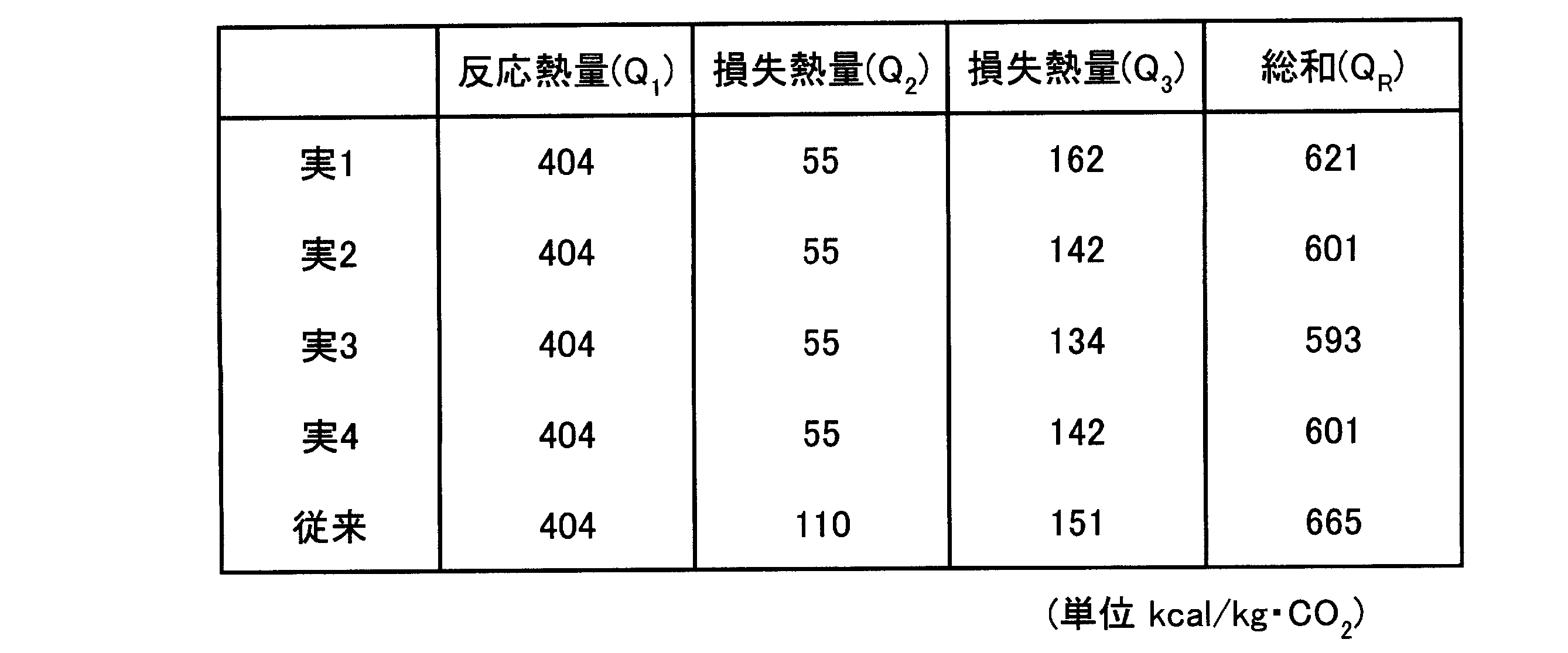
表1に示すように、実施例3のシステムが一番エネルギー効率が良好であることが判明した。
11 ボイラ
12 排ガス
15 CO2吸収液(リーン溶液)
15A 第1のリーン吸収液(第1のリーン溶液)
15B 第2のリーン吸収液(第2のリーン溶液)
15C 第3のリーン吸収液(第3のリーン溶液)
16 CO2吸収塔
17 リッチ溶液
18-1 第1の吸収液再生塔
18-2 第2の吸収液再生塔
Claims (5)
- 冷却されたCO2を含有する排ガスとCO2を吸収するCO2吸収液とを接触させて前記排ガスからCO2を除去するCO2吸収塔と、
CO2を吸収したCO2吸収液からCO2を放出させて吸収液を再生する第1の吸収液再生塔と、
第1の吸収液再生塔から排出された第1のリーン溶液から残存するCO2を放出させて吸収液を再生する第2の吸収液再生塔と、
第2の吸収液再生塔から排出された第2のリーン溶液をフラッシュさせるフラッシュドラムとを有してなり、
該フラッシュドラムで発生した蒸気を第1の吸収液再生塔に投入することを特徴とするCO2回収システム。 - 請求項1において、
第1のリーン溶液と前記フラッシュドラムでフラッシュさせた第3のリーン溶液とを熱交換するリーン・リーン溶液熱交換器を有することを特徴とするCO2回収システム。 - 請求項1において、
第1の吸収液再生塔の塔内部の鉛直軸方向の中間部分で、セミリーン溶液を抜き出すポートと、
セミリーン溶液が抜き出され、抜き出しポートより底部側の戻し入れポートに戻しいれる循環ラインと、
循環ラインに介装され、フラッシュドラムでフラッシュさせた第3のリーン溶液とセミリーン溶液とが熱交換するセミリーン・リーン溶液熱交換器と、を有することを特徴とするCO2回収システム。 - 請求項1において、
第1のリーン溶液と、フラッシュドラムでフラッシュさせた第3のリーン溶液とを熱交換するリーン・リーン溶液熱交換器と、
第1の吸収液再生塔の塔内部の鉛直軸方向の中間部分で、セミリーン溶液を抜き出すポートと、
セミリーン溶液が抜き出され、抜き出しポートより底部側の戻し入れポートに戻しいれる循環ラインと、
循環ラインに介装され、前記第3のリーン溶液とセミリーン溶液とを熱交換するセミリーン・リーン溶液熱交換器と、を有することを特徴とするCO2回収システム。 - 請求項1乃至4のいずれか一つにおいて、
CO2を含有する排ガスを冷却水によって冷却する冷却塔を有することを特徴とするCO2回収システム。
Priority Applications (5)
| Application Number | Priority Date | Filing Date | Title |
|---|---|---|---|
| CA2814354A CA2814354C (en) | 2010-12-01 | 2011-07-27 | Co2 recovery system |
| EP20171430.0A EP3708241B1 (en) | 2010-12-01 | 2011-07-27 | C02 recovery system |
| US13/879,298 US8728220B2 (en) | 2010-12-01 | 2011-07-27 | CO2 recovery system |
| EP11845355.4A EP2659949B1 (en) | 2010-12-01 | 2011-07-27 | C02 recovery system |
| AU2011338127A AU2011338127B2 (en) | 2010-12-01 | 2011-07-27 | CO2 recovery system |
Applications Claiming Priority (2)
| Application Number | Priority Date | Filing Date | Title |
|---|---|---|---|
| JP2010-268865 | 2010-12-01 | ||
| JP2010268865A JP5591083B2 (ja) | 2010-12-01 | 2010-12-01 | Co2回収システム |
Publications (1)
| Publication Number | Publication Date |
|---|---|
| WO2012073553A1 true WO2012073553A1 (ja) | 2012-06-07 |
Family
ID=46171509
Family Applications (1)
| Application Number | Title | Priority Date | Filing Date |
|---|---|---|---|
| PCT/JP2011/067158 Ceased WO2012073553A1 (ja) | 2010-12-01 | 2011-07-27 | Co2回収システム |
Country Status (6)
| Country | Link |
|---|---|
| US (1) | US8728220B2 (ja) |
| EP (2) | EP3708241B1 (ja) |
| JP (1) | JP5591083B2 (ja) |
| AU (1) | AU2011338127B2 (ja) |
| CA (2) | CA2814354C (ja) |
| WO (1) | WO2012073553A1 (ja) |
Cited By (1)
| Publication number | Priority date | Publication date | Assignee | Title |
|---|---|---|---|---|
| WO2024201895A1 (ja) | 2023-03-30 | 2024-10-03 | 三菱重工業株式会社 | 二酸化炭素回収システム |
Families Citing this family (8)
| Publication number | Priority date | Publication date | Assignee | Title |
|---|---|---|---|---|
| EP2481466A1 (de) * | 2011-01-31 | 2012-08-01 | Siemens Aktiengesellschaft | Vorrichtung und Verfahren zum Aufreinigen eines mit Nitrosamin verunreinigten Produktes einer Prozessanlage |
| JP5398755B2 (ja) * | 2011-02-08 | 2014-01-29 | 株式会社日立製作所 | Co2回収方法およびco2回収装置 |
| JP6071622B2 (ja) * | 2013-02-21 | 2017-02-01 | 三菱重工業株式会社 | Co2及びh2sを含むガスの回収システム及び方法 |
| JP5995746B2 (ja) * | 2013-02-21 | 2016-09-21 | 三菱重工業株式会社 | Co2及びh2sを含むガスの回収システム及び方法 |
| FR3008898B1 (fr) * | 2013-07-23 | 2023-01-13 | Electricite De France | Dispositif de captage de gaz acide contenu dans des fumees de combustion |
| CN116059786A (zh) * | 2021-10-29 | 2023-05-05 | 中石化南京化工研究院有限公司 | 一种脱碳液的再生方法 |
| CN115634566A (zh) * | 2022-10-28 | 2023-01-24 | 大连理工大学 | 一种利用低温热的mdea半贫循环脱硫装置及方法 |
| FR3162643A1 (fr) * | 2024-05-28 | 2025-12-05 | Commissariat A L'energie Atomique Et Aux Energies Alternatives | Procédé de capture de dioxyde de carbone |
Citations (4)
| Publication number | Priority date | Publication date | Assignee | Title |
|---|---|---|---|---|
| JPS4810712B1 (ja) * | 1968-03-22 | 1973-04-06 | ||
| JPS5040472A (ja) * | 1973-02-16 | 1975-04-14 | ||
| JPS54150372A (en) * | 1978-05-19 | 1979-11-26 | Hitachi Ltd | Separating method for h2s and co2 from gas mixture selectively |
| WO2005097299A1 (ja) * | 2004-03-15 | 2005-10-20 | Mitsubishi Heavy Industries, Ltd. | Co2回収装置及び方法 |
Family Cites Families (12)
| Publication number | Priority date | Publication date | Assignee | Title |
|---|---|---|---|---|
| IT1156991B (it) * | 1978-04-27 | 1987-02-04 | Giuseppe Giammarco | Procedimento migliorato per la purificazione di liquidi e o per la rigenerazione di soluzioni assorbenti |
| JP2792777B2 (ja) * | 1992-01-17 | 1998-09-03 | 関西電力株式会社 | 燃焼排ガス中の炭酸ガスの除去方法 |
| JPH0751537A (ja) | 1993-06-30 | 1995-02-28 | Mitsubishi Heavy Ind Ltd | Co2 含有ガス中のco2 を除去する方法 |
| US6800120B1 (en) | 1998-11-23 | 2004-10-05 | Fluor Corporation | Split-flow process and apparatus |
| US6165433A (en) | 1999-06-10 | 2000-12-26 | Praxair Technology, Inc. | Carbon dioxide recovery with composite amine blends |
| JP4523691B2 (ja) * | 2000-03-10 | 2010-08-11 | 三菱重工業株式会社 | 脱炭酸設備の吸収液の制御方法及び装置 |
| EP1551532B1 (en) * | 2002-07-03 | 2008-11-19 | Fluor Corporation | Improved split flow apparatus |
| JP4745682B2 (ja) * | 2005-02-23 | 2011-08-10 | 関西電力株式会社 | Co2回収装置および方法 |
| EP1962983A4 (en) | 2005-12-19 | 2010-01-06 | Fluor Tech Corp | INTEGRATED COMPRESSOR / UNIT COMPRESSOR METHODS AND CONFIGURATIONS |
| JP4773865B2 (ja) * | 2006-04-13 | 2011-09-14 | 三菱重工業株式会社 | Co2回収装置及びco2回収方法 |
| US8080089B1 (en) * | 2008-04-14 | 2011-12-20 | Bechtel Power Corporation | Method and apparatus for efficient gas treating system |
| US8123842B2 (en) * | 2009-01-16 | 2012-02-28 | Uop Llc | Direct contact cooling in an acid gas removal process |
-
2010
- 2010-12-01 JP JP2010268865A patent/JP5591083B2/ja active Active
-
2011
- 2011-07-27 EP EP20171430.0A patent/EP3708241B1/en active Active
- 2011-07-27 US US13/879,298 patent/US8728220B2/en active Active
- 2011-07-27 CA CA2814354A patent/CA2814354C/en active Active
- 2011-07-27 CA CA2894307A patent/CA2894307C/en active Active
- 2011-07-27 EP EP11845355.4A patent/EP2659949B1/en active Active
- 2011-07-27 AU AU2011338127A patent/AU2011338127B2/en active Active
- 2011-07-27 WO PCT/JP2011/067158 patent/WO2012073553A1/ja not_active Ceased
Patent Citations (4)
| Publication number | Priority date | Publication date | Assignee | Title |
|---|---|---|---|---|
| JPS4810712B1 (ja) * | 1968-03-22 | 1973-04-06 | ||
| JPS5040472A (ja) * | 1973-02-16 | 1975-04-14 | ||
| JPS54150372A (en) * | 1978-05-19 | 1979-11-26 | Hitachi Ltd | Separating method for h2s and co2 from gas mixture selectively |
| WO2005097299A1 (ja) * | 2004-03-15 | 2005-10-20 | Mitsubishi Heavy Industries, Ltd. | Co2回収装置及び方法 |
Cited By (2)
| Publication number | Priority date | Publication date | Assignee | Title |
|---|---|---|---|---|
| WO2024201895A1 (ja) | 2023-03-30 | 2024-10-03 | 三菱重工業株式会社 | 二酸化炭素回収システム |
| EP4670823A1 (en) | 2023-03-30 | 2025-12-31 | Mitsubishi Heavy Industries, Ltd. | CARBON DIOXIDE RECOVERY SYSTEM |
Also Published As
| Publication number | Publication date |
|---|---|
| US20130192470A1 (en) | 2013-08-01 |
| EP2659949A1 (en) | 2013-11-06 |
| CA2814354A1 (en) | 2012-06-07 |
| CA2894307C (en) | 2017-01-17 |
| EP3708241A1 (en) | 2020-09-16 |
| EP2659949A4 (en) | 2017-05-03 |
| CA2814354C (en) | 2016-03-15 |
| EP2659949B1 (en) | 2020-06-03 |
| JP5591083B2 (ja) | 2014-09-17 |
| AU2011338127B2 (en) | 2015-08-20 |
| CA2894307A1 (en) | 2012-06-07 |
| EP3708241B1 (en) | 2021-12-08 |
| AU2011338127A1 (en) | 2013-05-02 |
| JP2012115780A (ja) | 2012-06-21 |
| US8728220B2 (en) | 2014-05-20 |
Similar Documents
| Publication | Publication Date | Title |
|---|---|---|
| JP5591083B2 (ja) | Co2回収システム | |
| EP2722097B1 (en) | Combustion exhaust gas treatment system and combustion exhaust gas treatment method | |
| JP4745682B2 (ja) | Co2回収装置および方法 | |
| JP5383338B2 (ja) | Co2回収装置及びco2回収方法 | |
| JP5922451B2 (ja) | Co2回収装置 | |
| JP5875245B2 (ja) | Co2回収システム及びco2ガス含有水分の回収方法 | |
| JP5737916B2 (ja) | Co2回収システム | |
| JP2012000538A (ja) | 二酸化炭素の回収方法及び回収装置 | |
| JP2013059727A (ja) | Co2回収装置およびco2回収方法 | |
| JP2008307520A (ja) | Co2又はh2s除去システム、co2又はh2s除去方法 | |
| JP5591075B2 (ja) | Co2及びh2sを含むガスの回収システム及び方法 | |
| JP5237204B2 (ja) | Co2回収装置及び方法 | |
| KR20170114802A (ko) | 탈거탑 탑상증기의 열에너지를 재활용한 이산화탄소 포집방법과 그 장치 | |
| CN104936678B (zh) | 含co2及h2s的气体的回收系统及回收方法 | |
| JP2011000528A (ja) | Co2回収装置及び方法 | |
| JP2025100030A (ja) | 二酸化炭素の回収装置及び回収方法 |
Legal Events
| Date | Code | Title | Description |
|---|---|---|---|
| 121 | Ep: the epo has been informed by wipo that ep was designated in this application |
Ref document number: 11845355 Country of ref document: EP Kind code of ref document: A1 |
|
| ENP | Entry into the national phase |
Ref document number: 2814354 Country of ref document: CA |
|
| WWE | Wipo information: entry into national phase |
Ref document number: 13879298 Country of ref document: US Ref document number: 2011845355 Country of ref document: EP |
|
| ENP | Entry into the national phase |
Ref document number: 2011338127 Country of ref document: AU Date of ref document: 20110727 Kind code of ref document: A |
|
| NENP | Non-entry into the national phase |
Ref country code: DE |