WO2012073557A1 - パネル接合構造 - Google Patents
パネル接合構造 Download PDFInfo
- Publication number
- WO2012073557A1 WO2012073557A1 PCT/JP2011/068646 JP2011068646W WO2012073557A1 WO 2012073557 A1 WO2012073557 A1 WO 2012073557A1 JP 2011068646 W JP2011068646 W JP 2011068646W WO 2012073557 A1 WO2012073557 A1 WO 2012073557A1
- Authority
- WO
- WIPO (PCT)
- Prior art keywords
- panel
- glass
- van
- outer panel
- inner panel
- Prior art date
- Legal status (The legal status is an assumption and is not a legal conclusion. Google has not performed a legal analysis and makes no representation as to the accuracy of the status listed.)
- Ceased
Links
Images


Classifications
-
- B—PERFORMING OPERATIONS; TRANSPORTING
- B62—LAND VEHICLES FOR TRAVELLING OTHERWISE THAN ON RAILS
- B62D—MOTOR VEHICLES; TRAILERS
- B62D25/00—Superstructure or monocoque structure sub-units; Parts or details thereof not otherwise provided for
- B62D25/02—Side panels
Definitions
- the present invention relates to a panel joint structure for a body in a rear compartment of a van type vehicle of both glass van specifications and panel van specifications.
- a van type vehicle having a wide rear vehicle compartment so that it can be effectively used as a luggage compartment is known.
- van type vehicles There are two types of van type vehicles, one with a glass van that can be used as a passenger compartment in the back of the vehicle and one with a panel van that specializes in the rear of the vehicle as a luggage compartment. It has been known.
- a glass window is provided on the side of the vehicle for securing visibility and for escape in an emergency.
- the panel van specification a glass window is not provided and the side surface of the vehicle is covered with a metal panel.
- the vehicle side described above is different depending on the presence or absence of the glass window, the vehicle side is configured by joining the inner panel disposed on the vehicle compartment side and the outer panel disposed on the vehicle exterior side. Are consistent.
- the inner panel that constitutes the side of the vehicle should be used in common for both the glass van specification and the panel van specification for the purpose of reducing manufacturing costs.
- Patent Document 1 an inner panel that can be used in common for both the glass van specification and the panel van specification is disclosed. Since the disclosed inner panel can be used in common for both the glass van specification and the panel van specification, the manufacturing cost for constructing the vehicle side surface of the vehicle rear compartment can be reduced. .
- spot welding was used for joining the inner panel and the outer panel. Even in the above-described panel van specification, if spot welding is used for joining the inner panel and the outer panel as in the glass van specification, this spot welded portion can be seen from the outside, resulting in poor appearance. Therefore, in such a panel van specification, it is desirable to join each other by interposing an adhesive between the inner panel and the outer panel, instead of joining using spot welding.
- the present invention has been made in view of such circumstances, and the problem to be solved by the present invention is in the panel joint structure of the body in the vehicle rear compartment of both the van type and the van type vehicle. While it is possible to set the welded portion where the outer panel is brought into contact with each other and welded to each other into the inner panel, a gap for interposing an adhesive can be provided between the inner panel and the outer panel, and thus joining by interposing the adhesive is also possible. In order to reduce the manufacturing cost, the inner panel can be used in common for both the glass van specification and the panel van specification.
- the panel joining structure according to the present invention employs the following means. That is, the panel joint structure according to the first aspect of the present invention is provided on the vehicle compartment side of a vehicle having a glass van specification in which glass is attached to a side opening and a panel van specification in which the side opening is covered with a panel.
- a gap for interposing an adhesive is formed between the plate-like substrate and the outer panel by contacting the outer panel. Characterized in that it is set to bedding planes.
- the seat surface portion of the inner panel can be set as a welded portion for the outer panel for a glass van specification vehicle.
- an inner panel can be joined to an outer panel of a glass van specification by welding.
- the seat surface part of an inner panel can be set as a management surface for adhesion
- the seat surface portion of the inner panel serving as the adhesion management surface can be brought into contact with the outer panel, and a gap for interposing the adhesive between the plate-like substrate of the inner panel and the outer panel can be formed.
- the inner panel can be bonded to the outer panel of the panel van specification with the adhesive interposed. Therefore, the inner panel can be joined to the outer panel of the glass van specification by welding, but can be joined to the outer panel of the panel van specification by interposing an adhesive, so that the manufacturing cost can be reduced. It can be used in common for both specifications and panel van specifications.
- the panel joint structure according to a second aspect of the present invention is the panel joint structure according to the first aspect of the invention, wherein the outer panel of the glass van specification is provided with an edge that is cut out in accordance with the arrangement shape of the glass to be attached.
- the inner panel has an edge portion formed in a bent shape to cover the edge of the outer panel of the glass van specification in the joined state, and the outer panel of the panel van specification is joined.
- a stepped shape corresponding to the edge portion of the inner panel is provided.
- the edge portion of the inner panel is formed to have a bent shape covering the edge of the glass van specification outer panel in the joined state.
- the edge of the inner panel is covered with the edge of the inner panel so as not to be exposed to the outside.
- the edge part of an inner panel and an outer panel can be set with the bending shape of an inner panel.
- the outer panel of the panel van specification is provided with a step shape that allows the end edge portion of the inner panel in the joined state to escape, the inner panel can be joined without interfering with the outer panel. Therefore, the inner panel can be used in common for both the glass van specification and the panel van specification.
- the edge portion of the outer panel and the inner panel is located on the inner panel. It can be set at the edge of the bent shape.
- the panel joint structure according to a third invention is the panel joint structure according to the first or second invention, wherein the seat surface portion of the inner panel is spaced apart from the plate-like base. And a plurality of them are provided.
- the seat surface portions of the inner panel that are set as the welding site or set as the adhesion management surface are spaced apart from each other with respect to the plate-like substrate. Since a plurality of parts are provided, a plurality of joints to the outer panel in the glass van specification and the panel van specification can be provided. As a result, the inner panel can be more reliably joined to the outer panel.
- the inner panel can be joined to the outer panel of the glass van specification by welding, and can be joined by interposing an adhesive to the outer panel of the panel van specification.
- both the glass van specification and the panel van specification can be used in common.
- the inner panel can be used in common for both the glass van specification and the panel van specification, but the edge portion of the outer panel and the inner panel is provided in the glass van specification. It can be set to the edge that forms the bent shape of the inner panel.
- the joining of the inner panel to the outer panel can be made more reliable.
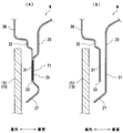
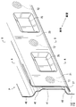
- FIG. 3 is a cross-sectional view showing an AA cross-section arrow and a BB cross-section arrow of FIG. 2. It is a perspective view which shows the van type panel junction structure of a panel van specification.
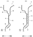
- FIG. 5 is a cross-sectional view showing an AA cross-section arrow and a BB cross-section arrow of FIG. 4.
- FIG. 1 shows the overall appearance of a van-type vehicle 10.
- the vehicle 10 is a so-called van type vehicle in which a vehicle rear chamber (shown by reference numeral 11) is set wide so that it can be effectively used as a luggage compartment.
- This van type vehicle 10 is a vehicle in which the vehicle rear chamber 11 can be opened and closed as a sliding door.
- the van type vehicle 10 has a glass van specification vehicle type that can use the vehicle rear compartment 11 as a passenger compartment as well as a luggage compartment, and a panel van specification that specializes in the vehicle rear compartment 11 as a luggage compartment.
- vehicle type There are two types of vehicle types: vehicle type.
- the window glass 151 is attached so that the window portion 15 is configured by the window glass 151.
- the window portion 15 is configured by the panel window portion 152 of the outer panel 40.
- the window portion 15 corresponds to a side opening according to the present invention.
- the panel joint structure W described in detail with reference to FIGS. 2 and 3 is a structure for forming a frame edge of the window part 15 of the glass van specification, and the window part 15 is configured by the window glass 151.
- FIG. 4 and 5 is a structure for forming a frame edge of the window portion 15 of the panel van specification, and the window portion 15 is formed on the panel window portion 152 of the outer panel 40.
- These panel joint structures W and P constitute a part of the vehicle body which is the vehicle side surface of the van type vehicle rear chamber 11, and the reference numeral 12 in the vehicle rear chamber 11 of the vehicle 10 shown in FIG. This is a structure that forms the frame edge (periphery of the side opening) of the window portion 15 in the elliptical portion.
- two types of specifications that is, a panel connection structure W with a glass van specification and a panel connection structure P with a panel van specification will be described separately.
- FIG. 2 is an enlarged perspective view showing a portion that is cut out by an ellipse in FIG. 3A is a cross-sectional view taken along the line AA in FIG. 3B is a cross-sectional view taken along the line BB in FIG.
- FIG. 2 shows only two seat surface portions 25 in an enlarged manner for easy understanding. As shown in FIG. 2 and FIG.
- the window portion 15 is configured by the window glass 151.
- the panel joint structure W has a frame edge structure of the window portion 15 of the window glass 151.
- the window glass 151 extends along the vehicle side surface direction.
- the panel joint structure W joins the inner panel 20 disposed on the vehicle compartment side and the outer panel 30 disposed on the vehicle exterior side.
- the outer panel 30 joined to the inner panel 20 in this way supports the window glass 151 via a glass window fixing means (not shown) such as a fixed molding member.
- the inner panel 20 is a panel disposed on the vehicle compartment side when constituting the body of the vehicle 10.
- the inner panel 20 is a common component that can be used in common for both the glass van specification and the panel van specification described later.
- the inner panel 20 includes a plate-like base 21 that extends along the vehicle side surface direction.
- the plate-like substrate 21 is formed in a substantially flat plate shape along the frame edge of the above-described window glass 151 in the inner panel 20.
- a plurality of seating surface portions 25 are arranged on the plate-like base body 21 along the frame edge direction of the window portion 15 at equal intervals spaced from each other.
- Each of the seating surface portions 25 has a shelf shape that rises so as to be pushed out from the plate-like base 21 to the vehicle exterior side.
- the seat surface portion 25 is formed to have a substantially planar shape facing the plate-like substrate 21 as a seat surface shape.
- the plurality of seating surface portions 25 are formed so as to be spaced apart from each other.
- These seat surface portions 25 are portions that are in surface contact with the outer panel 30. That is, the seat surface portion 25 is set as a welding part T1 that is welded in a surface contact state to the opposing flat plate portion 31 of the outer panel 30 when the inner panel 20 is joined to the outer panel 30.
- the seat surface portion 25 is brought into surface contact with the opposed flat plate portion 31 of the outer panel 30, there is a gap between the plate-like base 21 and the opposed flat plate portion 31 of the outer panel 30 in a non-contact state. It is formed.
- the seat surface portion 25 of the inner panel 20 is set as a portion that is in surface contact with the opposing flat plate portion 31 of the outer panel 40.
- the inner side of the frame edge of the plate-like substrate 21 is formed as an edge 27 of the inner panel 20.
- the peripheral portion (edge portion) of the edge 27 is formed to have a bent shape capable of covering the edge 33 of the outer panel 30 in the joined state.
- the edge 27 of the inner panel 20 is formed in a shape that bends toward the outside of the vehicle so as to cover an edge 33 of the outer panel 30 described below without interfering with the window glass 151.
- the opposing flat plate portion 31 extending along the vehicle side surface direction is formed as in the plate-like base 21 of the inner panel 20 described above.
- the opposing flat plate portion 31 is configured in a substantially flat plate shape along the frame edge of the above-described window glass 151 in the outer panel 30, similarly to the plate-like substrate 21.
- An edge 33 of the outer panel 30 is formed inside the frame edge of the opposing flat plate portion 31.
- the edge 33 of the outer panel 30 is formed so as to be cut out corresponding to the arrangement shape of the window glass 151.
- the part (illustration number 32) on the opposite side to the edge 33 of the outer panel 30 with respect to the opposing flat plate part 31 is formed in the appropriate bending shape so that it may become advantageous to arrangement
- the opposed flat plate portion 31 of the outer panel 30 is in surface contact with the seat surface portion 25 of the inner panel 20 as shown in FIG.
- the seat surface portion 25 of the inner panel 20 that is in surface contact with the opposed flat plate portion 31 of the outer panel 30 is set as a welding portion T1.
- the outer panel 30 and the inner panel 20 are joined by welding the welded portion T1 to the opposing flat plate portion 31 of the outer panel 30.
- the seat surface portion 25 of the inner panel 20 is brought into surface contact with the opposed flat plate portion 31 of the outer panel 30, there is a gap between the plate-like base 21 of the inner panel 20 and the opposed flat plate portion 31 of the outer panel 30. It is formed.
- FIGS. 4 and 5 a panel-type van type panel joint structure P will be described with reference to FIGS. 4 and 5.
- This panel joint structure P is an example in which the window portion 15 of the vehicle 10 shown in FIG. That is, the window portion 15 described above is configured by the window glass 151 in the glass van specification, but is configured by the panel window portion 152 of the outer panel 30 in the panel van specification. Therefore, in the description of the panel joint specification panel joint structure P, the outer panel 40 having a shape different from that of the glass van specification panel joint structure W will be mainly described.
- the inner panel 20 of the panel joining structure P of the panel van specification is an inner panel 20 of a common part that can be commonly used in the panel joining structure W of the glass van specification.
- FIG. 4 is an enlarged perspective view showing a portion that is cut out by an ellipse in FIG.
- FIG. 5A is a cross-sectional view taken along the line AA in FIG.
- FIG. 5B is a cross-sectional view taken along the line BB in FIG.
- FIG. 4 is an enlarged view of only the two seating surface portions 25, as in FIG.
- the panel joint structure P has a frame edge structure of the window portion 15 of the panel window portion 152.
- Panel window portion 152 extends along the vehicle side surface direction.
- the panel joint structure P joins the inner panel 20 disposed on the passenger compartment side and the outer panel 40 disposed on the vehicle exterior side.
- the outer panel 30 of the glass van specification described above is provided with the edge 33 that is cut out in accordance with the arrangement shape of the window glass 151.
- the outer panel 40 of the panel van specification is not cut out and extends. That is, the outer panel 40 of the panel van specification is formed with the opposing flat plate portion 41 extending along the vehicle side surface direction, like the outer panel 30 of the glass van specification.
- the opposing flat plate portion 41 is configured in a substantially flat plate shape along the frame edge of the above-described window glass 151 in the outer panel 30, similarly to the plate-like substrate 21.
- a panel window portion 152 of the outer panel 40 is formed inside the frame edge of the opposing flat plate portion 41.
- the panel window portion 152 of the outer panel 30 forms the window portion 15.
- symbol 42) on the opposite side to the panel window part 152 of the outer panel 30 with respect to the opposing flat plate part 31 is formed in the appropriate bending shape so that it may become advantageous to arrangement
- a step shape (denoted by reference numeral 43) is formed between the opposed flat plate portion 41 and the panel window portion 152 so as to release the end edge 27 of the inner panel 20 in the joined state.
- the opposed flat plate portion 41 of the outer panel 40 is in surface contact with the seat surface portion 25 of the inner panel 20. That is, the seat surface portion 25 of the inner panel 20 is set as an adhesion management surface that is in surface contact with the opposed flat plate portion 41 with respect to the outer panel 40 of the panel van specification.
- the seat surface portion 25 of the inner panel 20 can be set as the welding portion T1 for the opposed flat plate portion 31 of the outer panel 30 for a glass van specification vehicle. Thereby, the inner panel 20 can be joined to the outer panel 30 of the glass van specification by welding. Further, according to the panel joint structures W and P, the seat surface portion 25 of the inner panel 20 can be set as an adhesion management surface that is brought into contact with the outer panel 40 for a panel van specification vehicle.
- the seat surface portion 25 of the inner panel 20 serving as the bonding management surface is brought into contact with the opposing flat plate portion 41 of the outer panel 40, and between the plate-like base 21 of the inner panel 20 and the opposing flat plate portion 41 of the outer panel 40.
- a gap (an area corresponding to the adhesive T2 interposed) in which the adhesive T2 is interposed can be formed. Therefore, the inner panel 20 can be joined to the outer panel 40 of the panel van specification with the adhesive T2 interposed. Therefore, while the structure of the inner panel 20 can be joined to the outer panel 30 of the glass van specification by welding (indicated by reference numeral T1), it can be joined to the outer panel 40 of the panel van specification by interposing an adhesive T2.
- the end edge 27 portion of the inner panel 20 is formed to have a bent shape that covers the edge 33 of the outer panel 30 of the glass van specification in the joined state.
- the edge 33 of the outer panel 30 of the glass van specification can be covered with the edge 27 of the inner panel 20 so as not to be exposed to the outside. Accordingly, in the glass van specification, the end edges 27 and 33 of the inner panel 20 and the outer panel 30 can be set by the bent shape of the inner panel 20.
- the panel van specification outer panel 40 is provided with a step shape (denoted by reference numeral 43) that allows the end edge 27 of the inner panel 20 in the joined state to escape, so that the inner panel 20 is joined without interfering with the outer panel 40. Can do. Therefore, the inner panel 20 can be used in common for both the glass van specification and the panel van specification. However, in the glass van specification, the edge 27 of the outer panel 30 and the inner panel 20, Thirty-three positions can be set by the edge 27 that forms the bent shape of the inner panel 20. Further, according to the above-described panel joint structures W and P, the seat surface portion 25 of the inner panel 20 that is set as the welding site T1 or set as the adhesion management surface is spaced from the plate-like base 21. Therefore, a plurality of joints to the outer panels 30 and 40 in the glass van specification and the panel van specification can be provided. Thereby, the joining of the inner panel 20 with respect to both outer panels 30 and 40 can be made more reliable.
- a step shape denoted by reference numeral 43
- the panel joint structure according to the present invention is not limited to the above-described embodiment, and may be configured by appropriately changing locations as follows.
- the plurality of seating surface portions 25 are provided at equal intervals with respect to the plate-like base 21.
- the seat portion according to the present invention is not limited to this uniform interval, but may be a plurality of the seat surface portions provided to be spaced apart from each other with respect to the plate-like substrate.
- the end edge 33 of the outer panel 30 is hidden by the end edge 27 portion of the inner panel 20 and is not exposed to the outside.
- the panel joining structure according to the present invention is not limited to this, and for example, a shape that aligns the end edge 33 of the outer panel 30 and the end edge 27 of the inner panel 20 may be selected.
Landscapes
- Engineering & Computer Science (AREA)
- Chemical & Material Sciences (AREA)
- Combustion & Propulsion (AREA)
- Transportation (AREA)
- Mechanical Engineering (AREA)
- Body Structure For Vehicles (AREA)
Abstract
Description
すなわち、本発明の第1の発明に係るパネル接合構造は、側面開口部にガラスが取付けられたガラスバン仕様と、側面開口部がパネルで覆われたパネルバン仕様とを有する車両の、車室側に配設されるインナパネルの開口部周縁と車外側に配設されるアウタパネルとのパネル接合構造であって、前記インナパネルは、車両側面方向に沿って延在する板状基体と、該板状基体から車外側に棚状に盛り上がる座面部とを備え、前記座面部は、前記ガラスバン仕様では、前記アウタパネルに溶接されることにより前記インナパネルを前記アウタパネルに接合する溶接部位に設定されており、前記パネルバン仕様では、前記アウタパネルに接触させることにより、前記板状基体と前記アウタパネルとの間に、接着剤を介在させる隙間を形成する接着用管理面に設定されることを特徴とする。
もって、インナパネルの構成を、ガラスバン仕様のアウタパネルに対して溶接により接合できつつ、パネルバン仕様のアウタパネルに対しては接着剤を介在させることにより接合できるものとし、製造コストの削減を図るようにガラスバン仕様とパネルバン仕様との両者に対して共通して利用できるものとなる。
この第2の発明に係るパネル接合構造によれば、インナパネルの端縁部分は、接合状態におけるガラスバン仕様のアウタパネルの端縁を覆う曲げ形状を有して形成されているので、ガラスバン仕様のアウタパネルの端縁をインナパネルの端縁部分によって覆い隠して外部に露出させないようにできる。これによって、ガラスバン仕様では、インナパネルとアウタパネルとの端縁個所をインナパネルの曲げ形状にて設定できる。また、パネルバン仕様のアウタパネルは、接合状態におけるインナパネルの端縁部分を逃がす段差形状が設けられているので、インナパネルをアウタパネルに干渉させることなく接合させることができる。したがって、ガラスバン仕様であっても、パネルバン仕様であっても、インナパネルを両者に対して共通して利用することができつつ、ガラスバン仕様では、アウタパネルとインナパネルとの端縁個所をインナパネルの曲げ形状となる端縁にて設定できる。
この第3の発明に係るパネル接合構造によれば、溶接部位として設定されたり接着用管理面として設定されたりするインナパネルの座面部は、板状基体に対して互いに離間する間隔を有して複数設けられているので、ガラスバン仕様およびパネルバン仕様におけるアウタパネルに対しての接合個所を複数に亘ったものとすることができる。これによって、アウタパネルに対するインナパネルの接合を、より確かなものとすることができる。
第2の発明に係るパネル接合構造によれば、ガラスバン仕様とパネルバン仕様との両者に対してインナパネルを共通して利用することができつつ、ガラスバン仕様ではアウタパネルとインナパネルとの端縁個所をインナパネルの曲げ形状となる端縁に設定できる。
第3の発明に係るパネル接合構造によれば、アウタパネルに対するインナパネルの接合を、より確かなものとすることができる。
図2および図3を用いて詳述するパネル接合構造Wは、ガラスバン仕様のウインドウ部位15の枠縁をなすための構造であり、ウインドウ部位15が窓ガラス151にて構成されている。これに対し、図4および図5を用いて詳述するパネル接合構造Pは、パネルバン仕様のウインドウ部位15の枠縁をなすための構造であり、ウインドウ部位15はアウタパネル40のパネル窓部152にて構成されている。なお、これらパネル接合構造W,Pは、バンタイプの車両後室11の車両側面となるボデーの一部を構成するものであり、図1に示す車両10の車両後室11における図示符号12の楕円部分のウインドウ部位15の枠縁(側面開口部周縁)をなす構造である。
以下では、ガラスバン仕様のパネル接合構造Wと、パネルバン仕様のパネル接合構造Pとの二種類の仕様について区分けして説明する。
まず、ガラスバン仕様のバンタイプのパネル接合構造Wについて、図2および図3を参照しながら説明する。このパネル接合構造Wは、図1に示す車両10のウインドウ部位15を窓ガラス151として構成する例である。図2および図3では、このガラスバン仕様のバンタイプのパネル接合構造Wを示している。すなわち、図2は、図1において楕円で刳り抜かれる部分を拡大して示す斜視図である。また、図3(A)は、図2におけるA-A断面矢視を示す断面図である。図3(B)は、図2におけるB-B断面矢視を示す断面図である。なお、図2は、分かり易くするために、多数形成される座面部25のうち、2つの座面部25だけを拡大して図示している。
図2および図3に示すように、ガラスバン仕様の車両タイプではウインドウ部位15を窓ガラス151で構成している。パネル接合構造Wは、この窓ガラス151のウインドウ部位15の枠縁の構造となっている。なお、この窓ガラス151は、車両側面方向に沿って延在する。ここでパネル接合構造Wは、車室側に配設されるインナパネル20と車外側に配設されるアウタパネル30とを接合している。なお、このようにインナパネル20と接合したアウタパネル30は、固定モール部材等の不図示のガラス窓固定手段を介して窓ガラス151を支持している。
板状基体21には、複数の座面部25がウインドウ部位15の枠縁方向に沿って、互いに離間した均等間隔にて並べられて設けられている。この座面部25は、それぞれ板状基体21から車外側に押し出されるように盛り上がった棚状をなしている。つまり、座面部25は、座面形状として板状基体21に対して面する略平面形状を有して形成される。これら複数の座面部25は、互いに離間する間隔を有して形成されている。これらの座面部25は、アウタパネル30に対して面接触する部分である。つまり、座面部25は、インナパネル20をアウタパネル30に接合するにあたって、アウタパネル30の対向平板部31に面接触状態にて溶接する溶接部位T1として設定される。なお、この座面部25をアウタパネル30の対向平板部31に面接触させた場合には、上記した板状基体21とアウタパネル30の対向平板部31との間には互いに非接触状態となる隙間が形成される。なお、後にも説明するが、インナパネル20の座面部25は、アウタパネル40の対向平板部31に対しても面接触する部位として設定される。
また、アウタパネル30にあっても、上記したインナパネル20の板状基体21と同様、車両側面方向に沿って延在する対向平板部31が形成されている。この対向平板部31は、板状基体21と同様、アウタパネル30のうち上記した窓ガラス151の枠縁に沿って略平板状に構成される。この対向平板部31の枠縁内側にはアウタパネル30の端縁33が形成されている。このアウタパネル30の端縁33は、窓ガラス151の配設形状に対応して切り欠かれるようにして形成されている。なお、対向平板部31に対してアウタパネル30の端縁33とは反対側の部分(図示符号32)は、窓ガラス151の配設に有利となるように適宜の屈曲形状にて形成されている。
なお、上記したようにアウタパネル30の対向平板部31は、図3(A)に示すように、インナパネル20の座面部25が面接触するようになっている。このアウタパネル30の対向平板部31に面接触したインナパネル20の座面部25は、溶接部位T1として設定される。アウタパネル30とインナパネル20とは、この溶接部位T1をアウタパネル30の対向平板部31に溶接することによって接合するようになっている。また、このインナパネル20の座面部25をアウタパネル30の対向平板部31に面接触させた場合には、インナパネル20の板状基体21とアウタパネル30の対向平板部31との間には隙間が形成される。
次に、パネルバン仕様のバンタイプのパネル接合構造Pについて、図4および図5を参照しながら説明する。このパネル接合構造Pは、図1に示す車両10のウインドウ部位15をアウタパネル30により構成する例である。つまり、上記したウインドウ部位15は、ガラスバン仕様では窓ガラス151で構成していたが、このパネルバン仕様ではアウタパネル30のパネル窓部152で構成する。このため、このパネルバン仕様のパネル接合構造Pの説明では、上記したガラスバン仕様のパネル接合構造Wと形状が相違するアウタパネル40について重点的に説明する。なお、このパネルバン仕様のパネル接合構造Pのインナパネル20は、上記したガラスバン仕様のパネル接合構造Wにおいて共通して利用できる共通部品のインナパネル20である。つまり、パネル接合構造Pのインナパネル20は上記したパネル接合構造Wのインナパネル20と同一の構成となっている。
図4および図5では、このパネルバン仕様のバンタイプのパネル接合構造Pを示している。すなわち、図4は、図1において楕円で刳り抜かれる部分を拡大して示す斜視図である。また、図5(A)は、図4におけるA-A断面矢視を示す断面図である。図5(B)は、図4におけるB-B断面矢視を示す断面図である。なお、図4は、上記した図2と同様、2つの座面部25だけを拡大して図示している。
ところで、上記したガラスバン仕様のアウタパネル30は、窓ガラス151の配設形状に対応して切り欠かれる端縁33が設けられていた。これに対してパネルバン仕様のアウタパネル40は、切り欠かれず延在したものとなっている。
すなわち、このパネルバン仕様のアウタパネル40は、ガラスバン仕様のアウタパネル30と同様、車両側面方向に沿って延在する対向平板部41が形成されている。この対向平板部41は、板状基体21と同様、アウタパネル30のうち上記した窓ガラス151の枠縁に沿って略平板状に構成される。この対向平板部41の枠縁内側にはアウタパネル40のパネル窓部152として形成されている。このアウタパネル30のパネル窓部152は、ウインドウ部位15をなす。なお、対向平板部31に対してアウタパネル30のパネル窓部152とは反対側の部分(図示符号42)は、窓ガラス151の配設に有利となるように適宜の屈曲形状にて形成されている。また、このアウタパネル40のうち、対向平板部41とパネル窓部152との間には、接合状態におけるインナパネル20の端縁27を逃がす段差形状(図示符号43)が形成されている。なお、上記したようにアウタパネル40の対向平板部41は、インナパネル20の座面部25が面接触するようになっている。つまり、このインナパネル20の座面部25は、パネルバン仕様のアウタパネル40に対しては、対向平板部41と面接触する接着用管理面として設定される。このため、このインナパネル20の座面部25をアウタパネル40の対向平板部41に面接触させた場合には、図5(B)に示すように、インナパネル20の板状基体21とアウタパネル40の対向平板部41との間には、接着剤T2を介在させるための隙間(接着剤T2介装相当部位)が形成される。なお、この接着剤T2を、インナパネル20の板状基体21とアウタパネル40の対向平板部41との間に介在させると、アウタパネル40とインナパネル20とを接合できることとなる。
すなわち、上記したパネル接合構造W,Pによれば、ガラスバン仕様の車両に対しては、インナパネル20の座面部25を、アウタパネル30の対向平板部31に対する溶接部位T1として設定することができる。これによって、ガラスバン仕様のアウタパネル30に対してインナパネル20を溶接により接合することができる。また、このパネル接合構造W,Pによれば、パネルバン仕様の車両に対しては、インナパネル20の座面部25を、アウタパネル40に接触させる接着用管理面として設定することができる。これによって、接着用管理面となるインナパネル20の座面部25をアウタパネル40の対向平板部41に接触させて、インナパネル20の板状基体21とアウタパネル40の対向平板部41にとの間に接着剤T2を介在させる隙間(接着剤T2介装相当部位)を形成することができる。したがって、パネルバン仕様のアウタパネル40に対してインナパネル20を接着剤T2を介在させて接合することができる。
もって、インナパネル20の構成を、ガラスバン仕様のアウタパネル30に対して溶接(図示符号T1)により接合できつつ、パネルバン仕様のアウタパネル40に対しては接着剤T2を介在させることにより接合できるものとし、製造コストの削減を図るようにガラスバン仕様とパネルバン仕様との両者に対して共通して利用できるものとなる。
また、上記したパネル接合構造W,Pによれば、インナパネル20の端縁27部分は、接合状態におけるガラスバン仕様のアウタパネル30の端縁33を覆う曲げ形状を有して形成されているので、ガラスバン仕様のアウタパネル30の端縁33をインナパネル20の端縁27部分によって覆い隠して外部に露出させないようにできる。これによって、ガラスバン仕様では、インナパネル20とアウタパネル30との端縁27,33個所をインナパネル20の曲げ形状にて設定できる。また、パネルバン仕様のアウタパネル40は、接合状態におけるインナパネル20の端縁27部分を逃がす段差形状(図示符号43)が設けられているので、インナパネル20をアウタパネル40に干渉させることなく接合させることができる。したがって、ガラスバン仕様であっても、パネルバン仕様であっても、インナパネル20を両者に対して共通して利用することができつつ、ガラスバン仕様では、アウタパネル30とインナパネル20との端縁27,33個所をインナパネル20の曲げ形状となる端縁27にて設定できる。
また、上記したパネル接合構造W,Pによれば、溶接部位T1として設定されたり接着用管理面として設定されたりするインナパネル20の座面部25は、板状基体21に対して互いに離間する間隔を有して複数設けられているので、ガラスバン仕様およびパネルバン仕様におけるアウタパネル30,40に対しての接合個所を複数に亘ったものとすることができる。これによって、両者のアウタパネル30,40に対するインナパネル20の接合を、より確かなものとすることができる。
例えば、上記した実施の形態のパネル接合構造W,Pにあっては、複数の座面部25が板状基体21に対して均等間隔で設けられるものとなっていた。しかしながら、本発明に係る座面部は、この均等間隔に限定されることなく、板状基体に対して互いに離間する間隔を有して複数設けられるものであればよい。
また、上記した実施の形態のパネル接合構造Wにあっては、アウタパネル30の端縁33はインナパネル20の端縁27部分によって隠されて外部に露出されないようにされていた。しかしながら、本発明に係るパネル接合構造は、これに限定されることなく、たとえばアウタパネル30の端縁33とインナパネル20の端縁27とを揃えるようにする形状が選択されてもよい。
11 車両後室
15 ウインドウ部位
151 窓ガラス
152 パネル窓部
20 インナパネル
21 板状基体
25 座面部
27 端縁
30,40 アウタパネル
31,41 対向平板部
32,42 屈曲形状
33 端縁
43 段差形状
W,P パネル接合構造
T1 溶接部位
T2 接着剤介装部位
Claims (3)
- 側面開口部にガラスが取付けられたガラスバン仕様と、側面開口部がパネルで覆われたパネルバン仕様とを有する車両の、車室側に配設されるインナパネルの開口部周縁と車外側に配設されるアウタパネルとのパネル接合構造であって、
前記インナパネルは、車両側面方向に沿って延在する板状基体と、該板状基体から車外側に棚状に盛り上がる座面部とを備え、
前記座面部は、
前記ガラスバン仕様では、前記アウタパネルに溶接されることにより前記インナパネルを前記アウタパネルに接合する溶接部位に設定されており、
前記パネルバン仕様では、前記アウタパネルに接触させることにより、前記板状基体と前記アウタパネルとの間に、接着剤を介在させる隙間を形成する接着用管理面に設定されることを特徴とするパネル接合構造。 - 請求項1に記載のパネル接合構造において、
前記ガラスバン仕様の前記アウタパネルは、取付けられる前記ガラスの配設形状に対応して切り欠かれる端縁が設けられており、
前記インナパネルの端縁部分は、接合状態における前記ガラスバン仕様の前記アウタパネルの前記端縁を覆う曲げ形状を有して形成されており、
前記パネルバン仕様の前記アウタパネルは、接合された前記インナパネルの前記端縁部分に対応した段差形状が設けられていることを特徴とするパネル接合構造。 - 請求項1または請求項2に記載のパネル接合構造において、
前記インナパネルの前記座面部は、前記板状基体に対して、互いに離間する間隔を有して複数設けられていることを特徴とするパネル接合構造。
Priority Applications (3)
| Application Number | Priority Date | Filing Date | Title |
|---|---|---|---|
| AU2011338131A AU2011338131B2 (en) | 2010-12-03 | 2011-08-18 | Panel-joining structure |
| EP11844419.9A EP2591985A4 (en) | 2010-12-03 | 2011-08-18 | PANEL ASSEMBLY STRUCTURE |
| CN2011800391809A CN103108797A (zh) | 2010-12-03 | 2011-08-18 | 面板接合结构 |
Applications Claiming Priority (2)
| Application Number | Priority Date | Filing Date | Title |
|---|---|---|---|
| JP2010270062A JP2012116419A (ja) | 2010-12-03 | 2010-12-03 | パネル接合構造 |
| JP2010-270062 | 2010-12-03 |
Publications (1)
| Publication Number | Publication Date |
|---|---|
| WO2012073557A1 true WO2012073557A1 (ja) | 2012-06-07 |
Family
ID=46171513
Family Applications (1)
| Application Number | Title | Priority Date | Filing Date |
|---|---|---|---|
| PCT/JP2011/068646 Ceased WO2012073557A1 (ja) | 2010-12-03 | 2011-08-18 | パネル接合構造 |
Country Status (5)
| Country | Link |
|---|---|
| EP (1) | EP2591985A4 (ja) |
| JP (1) | JP2012116419A (ja) |
| CN (1) | CN103108797A (ja) |
| AU (1) | AU2011338131B2 (ja) |
| WO (1) | WO2012073557A1 (ja) |
Cited By (2)
| Publication number | Priority date | Publication date | Assignee | Title |
|---|---|---|---|---|
| CN104842753A (zh) * | 2014-12-19 | 2015-08-19 | 北汽福田汽车股份有限公司 | 车身盲窗结构和载货车辆 |
| CN110254517A (zh) * | 2019-07-01 | 2019-09-20 | 安徽安凯汽车股份有限公司 | 一种客车车身侧围蒙皮结构及蒙皮工艺 |
Families Citing this family (2)
| Publication number | Priority date | Publication date | Assignee | Title |
|---|---|---|---|---|
| CN103625556A (zh) * | 2013-12-06 | 2014-03-12 | 上汽通用五菱汽车股份有限公司 | 一种汽车前门外板窗台加强板及汽车前门 |
| JP6570672B2 (ja) * | 2018-02-02 | 2019-09-04 | 本田技研工業株式会社 | ポップアップガラス構造 |
Citations (3)
| Publication number | Priority date | Publication date | Assignee | Title |
|---|---|---|---|---|
| JPH0259880U (ja) * | 1988-10-17 | 1990-05-01 | ||
| JP2004082136A (ja) * | 2002-08-23 | 2004-03-18 | Toyota Auto Body Co Ltd | 鋼板接合構造 |
| JP2010162986A (ja) | 2009-01-14 | 2010-07-29 | Nissan Motor Co Ltd | 車体開口部構造 |
Family Cites Families (2)
| Publication number | Priority date | Publication date | Assignee | Title |
|---|---|---|---|---|
| DE4406615B4 (de) * | 1994-03-01 | 2007-11-08 | Daimlerchrysler Ag | Verfahren zum Herstellen einer Rohbaustruktur für ein Kraftfahrzeug |
| JP4265647B2 (ja) * | 2006-11-29 | 2009-05-20 | トヨタ自動車株式会社 | 車体側部構造 |
-
2010
- 2010-12-03 JP JP2010270062A patent/JP2012116419A/ja active Pending
-
2011
- 2011-08-18 CN CN2011800391809A patent/CN103108797A/zh active Pending
- 2011-08-18 AU AU2011338131A patent/AU2011338131B2/en not_active Ceased
- 2011-08-18 EP EP11844419.9A patent/EP2591985A4/en not_active Withdrawn
- 2011-08-18 WO PCT/JP2011/068646 patent/WO2012073557A1/ja not_active Ceased
Patent Citations (3)
| Publication number | Priority date | Publication date | Assignee | Title |
|---|---|---|---|---|
| JPH0259880U (ja) * | 1988-10-17 | 1990-05-01 | ||
| JP2004082136A (ja) * | 2002-08-23 | 2004-03-18 | Toyota Auto Body Co Ltd | 鋼板接合構造 |
| JP2010162986A (ja) | 2009-01-14 | 2010-07-29 | Nissan Motor Co Ltd | 車体開口部構造 |
Non-Patent Citations (1)
| Title |
|---|
| See also references of EP2591985A4 * |
Cited By (2)
| Publication number | Priority date | Publication date | Assignee | Title |
|---|---|---|---|---|
| CN104842753A (zh) * | 2014-12-19 | 2015-08-19 | 北汽福田汽车股份有限公司 | 车身盲窗结构和载货车辆 |
| CN110254517A (zh) * | 2019-07-01 | 2019-09-20 | 安徽安凯汽车股份有限公司 | 一种客车车身侧围蒙皮结构及蒙皮工艺 |
Also Published As
| Publication number | Publication date |
|---|---|
| EP2591985A4 (en) | 2014-04-23 |
| EP2591985A1 (en) | 2013-05-15 |
| AU2011338131B2 (en) | 2014-05-01 |
| AU2011338131A1 (en) | 2013-02-28 |
| JP2012116419A (ja) | 2012-06-21 |
| CN103108797A (zh) | 2013-05-15 |
Similar Documents
| Publication | Publication Date | Title |
|---|---|---|
| EP3034341B1 (en) | Vehicular resin back door structure | |
| WO2009051174A1 (ja) | 車両のドアミラー取付構造 | |
| JP6179162B2 (ja) | 車両用ドアのフレームモール | |
| CN108146208B (zh) | 车身结构 | |
| JP6416843B2 (ja) | ドアシール構造 | |
| JP2012116419A (ja) | パネル接合構造 | |
| CN105691324A (zh) | 一种柔性塑料卡扣座 | |
| CN106608166B (zh) | 汽车用车门构造 | |
| JP6756046B2 (ja) | 車両のルーフ構造体 | |
| JP4867829B2 (ja) | 車両用サイドステップ | |
| JP4322200B2 (ja) | バックドア | |
| JP2017154718A (ja) | 車両のドア構造 | |
| JP2016203892A (ja) | ガラスランの固定構造 | |
| JP2012011804A (ja) | ドアトリム | |
| JP4605595B2 (ja) | 車体の板金接合構造 | |
| JP2012101725A (ja) | 自動車のフード構造 | |
| CN109950342A (zh) | 太阳能电池模块 | |
| JP5134919B2 (ja) | 車両用ドアサッシュ構造 | |
| CN103648892A (zh) | 汽车的绝缘子安装构造 | |
| JP5217487B2 (ja) | フェンダ端部の遮音構造 | |
| JP4962242B2 (ja) | パネル材の合わせ部構造 | |
| CN104108300B (zh) | 车辆的开闭体 | |
| JP4219214B2 (ja) | 自動車のドア構造 | |
| JP4318955B2 (ja) | 車両のリヤゲート構造 | |
| JP5659528B2 (ja) | 車両のウインドシールド構造 |
Legal Events
| Date | Code | Title | Description |
|---|---|---|---|
| WWE | Wipo information: entry into national phase |
Ref document number: 201180039180.9 Country of ref document: CN |
|
| 121 | Ep: the epo has been informed by wipo that ep was designated in this application |
Ref document number: 11844419 Country of ref document: EP Kind code of ref document: A1 |
|
| WWE | Wipo information: entry into national phase |
Ref document number: 2011844419 Country of ref document: EP |
|
| ENP | Entry into the national phase |
Ref document number: 2011338131 Country of ref document: AU Date of ref document: 20110818 Kind code of ref document: A |
|
| NENP | Non-entry into the national phase |
Ref country code: DE |