WO2012073697A1 - 移動通信網および無線基地局 - Google Patents
移動通信網および無線基地局 Download PDFInfo
- Publication number
- WO2012073697A1 WO2012073697A1 PCT/JP2011/076424 JP2011076424W WO2012073697A1 WO 2012073697 A1 WO2012073697 A1 WO 2012073697A1 JP 2011076424 W JP2011076424 W JP 2011076424W WO 2012073697 A1 WO2012073697 A1 WO 2012073697A1
- Authority
- WO
- WIPO (PCT)
- Prior art keywords
- base station
- radio base
- correction value
- radio
- received
- Prior art date
- Legal status (The legal status is an assumption and is not a legal conclusion. Google has not performed a legal analysis and makes no representation as to the accuracy of the status listed.)
- Ceased
Links
Images




Classifications
-
- H—ELECTRICITY
- H04—ELECTRIC COMMUNICATION TECHNIQUE
- H04W—WIRELESS COMMUNICATION NETWORKS
- H04W52/00—Power management, e.g. Transmission Power Control [TPC] or power classes
- H04W52/04—Transmission power control [TPC]
- H04W52/18—TPC being performed according to specific parameters
- H04W52/24—TPC being performed according to specific parameters using SIR [Signal to Interference Ratio] or other wireless path parameters
- H04W52/243—TPC being performed according to specific parameters using SIR [Signal to Interference Ratio] or other wireless path parameters taking into account interferences
- H04W52/244—Interferences in heterogeneous networks, e.g. among macro and femto or pico cells or other sector / system interference [OSI]
-
- H—ELECTRICITY
- H04—ELECTRIC COMMUNICATION TECHNIQUE
- H04W—WIRELESS COMMUNICATION NETWORKS
- H04W28/00—Network traffic management; Network resource management
- H04W28/02—Traffic management, e.g. flow control or congestion control
-
- H—ELECTRICITY
- H04—ELECTRIC COMMUNICATION TECHNIQUE
- H04W—WIRELESS COMMUNICATION NETWORKS
- H04W16/00—Network planning, e.g. coverage or traffic planning tools; Network deployment, e.g. resource partitioning or cells structures
- H04W16/24—Cell structures
- H04W16/32—Hierarchical cell structures
-
- H—ELECTRICITY
- H04—ELECTRIC COMMUNICATION TECHNIQUE
- H04W—WIRELESS COMMUNICATION NETWORKS
- H04W48/00—Access restriction; Network selection; Access point selection
- H04W48/02—Access restriction performed under specific conditions
- H04W48/06—Access restriction performed under specific conditions based on traffic conditions
Definitions
- the present invention relates to a technique for controlling each radio base station in a mobile communication network including a plurality of types of radio base stations having different communication powers.
- Non-Patent Document 1 discloses a technique (range extension) for extending a cell (pico cell) formed by a pico base station. range extension is also called cell range expansion.
- the opportunity for selecting a pico base station as a connection destination of a mobile terminal certainly increases.
- the pico cell is expanded equally for a plurality of pico base stations, the number of mobile terminal connections increases in a pico base station at a position where a large number of mobile terminals are concentrated.
- the communication speed (throughput) decreases in the pico base station where the connection of mobile terminals is concentrated.
- the present invention improves communication efficiency by reducing the concentration of terminal connections to a specific radio base station in a mobile communication network including a plurality of types of radio base stations having different communication powers. Objective.
- the mobile communication network is a mobile communication network that measures or calculates a received radio wave characteristic value indicating a characteristic of a radio wave received from each radio base station and selects a radio base station according to each received radio wave characteristic value.
- a mobile communication network comprising a plurality of radio base stations each capable of radio communication with a terminal, the plurality of radio base stations comprising a first radio base station forming a first cell, and a first cell
- a plurality of second radio base stations each forming a second cell having a small area in the first cell, and each of the plurality of second radio base stations determines a communication load index of the second radio base station.
- a load measuring unit to measure or calculate, and a correction value for changing the received radio wave characteristic value of the radio wave received by the mobile terminal from the second radio base station at the mobile terminal are variably set according to the communication load index If the communication load index is below the first threshold
- a correction value setting unit that increases the positive value and decreases the correction value when the communication load index exceeds the second threshold value that is larger than the first threshold value, and notifies the mobile terminal of the correction value set by the correction value setting unit.
- a correction value notification unit is provided.
- the substantial area of the second cell formed by each second radio base station (that is, the substantial communication power of the second radio base station) is the communication load of the second radio base station. Therefore, there is an advantage that the concentration of terminal connections with respect to a specific second radio base station is alleviated.
- a specific example of the first aspect will be described later as the first embodiment, for example.
- the present invention can also be specified as a radio base station (for example, the pico base station 24) employed as the second radio base station in the mobile communication network of the first aspect.
- the mobile communication network is a mobile communication network that measures or calculates a received radio wave characteristic value indicating a characteristic of a radio wave received from each radio base station and selects a radio base station according to each received radio wave characteristic value.
- a mobile communication network comprising a plurality of radio base stations each capable of radio communication with a terminal, the plurality of radio base stations comprising a first radio base station forming a first cell, and a first cell
- a plurality of second radio base stations each forming a second cell having a small area in the first cell, and each of the plurality of second radio base stations performs radio communication with the first radio base station.
- Correction value can be set according to the received power measured by the power measurement unit.
- each second radio base station since the substantial area of the second cell formed by each second radio base station is adjusted according to the distance between the second radio base station and the first radio base station, there is an advantage that concentration of terminal connection to the first radio base station and concentration of terminal connection to a specific second radio base station are alleviated.
- a specific example of the second mode will be described later as a second embodiment, for example.
- the present invention can also be specified as a radio base station employed as the second radio base station in the mobile communication network of the second aspect.
- the mobile communication network is a mobile communication device that measures or calculates a received radio wave characteristic value indicating a characteristic of a radio wave received from each radio base station and selects a radio base station corresponding to each received radio wave characteristic value.
- a mobile communication network comprising a plurality of radio base stations each capable of radio communication with a terminal, the plurality of radio base stations comprising a first radio base station forming a first cell, and a first cell
- a plurality of second radio base stations each forming a second cell with a small area in the first cell, the first radio base station comprising the first radio base station, the plurality of second radio base stations, And a correction value for changing the received radio wave characteristic value of the radio wave received by each mobile terminal from each second radio base station at the mobile terminal.
- a correction value setting unit that is variably set for each second radio base station so as to increase from the second radio base station, and each correction value set by the correction value setting unit for each second radio base station via the second radio base station
- a correction value notification unit for notifying the mobile terminal.
- the correction value is individually set for each second radio base station so that the total communication speed increases, the first radio base station and the plurality of second radio base stations are There is an advantage that concentration of terminal connection with respect to the first radio base station and concentration of terminal connection with respect to the specific second radio base station are alleviated while improving overall communication efficiency.
- a specific example of the third aspect will be described later as a third embodiment, for example.
- the present invention can also be specified as a radio base station employed as the first radio base station in the mobile communication network of the third aspect.
- FIG. 1 is a block diagram of a wireless communication system according to a first embodiment of the present invention. It is a block diagram of the mobile terminal in a radio
- FIG. 1 is a block diagram of a wireless communication system 100 according to the first embodiment of this invention.
- the wireless communication system 100 includes a mobile communication network 12 and a plurality of mobile terminals 14.
- the mobile communication network 12 is a communication network that provides each mobile terminal 14 with wireless communication services such as voice call and data communication, and includes a plurality of wireless base stations 20 connected to each other.
- Each radio base station 20 performs radio communication with the mobile terminal 14 located in the cell C (Cm, Cp) formed by itself.
- Each radio base station 20 may be an NB (Node B) in UMTS or an e-Node B in UMTS (Universal Mobile Telecommunications System) LTE (Long Term Evolution).
- the mobile terminal 14 is, for example, a mobile phone (UE (User Equipment) in UMTS LTE) and communicates with other communication devices (other mobile terminals 14 and server devices) via each radio base station 20 of the mobile communication network 12. connect.
- the radio communication method between the radio base station 20 and the mobile terminal 14 is arbitrary. For example, OFDMA (Orthogonal Frequency Division Multiple Acceess) is adopted in the downlink direction, and SC-FDMA (Single -Carrier Frequency Division Multiple Access).
- OFDMA Orthogonal Frequency Division Multiple Acceess
- SC-FDMA Single -Carrier Frequency Division Multiple Access
- the plurality of radio base stations 20 of the mobile communication network 12 are classified into a macro base station 22 and a pico base station 24 having different communication powers.
- a plurality of pico base stations 24 are connected to each macro base station 22.
- FIG. 1 only one macro base station 22 is shown for convenience, but actually, a large number of macro base stations 22 connected to each other are arranged, and a plurality of pico base stations 24 are connected to each.
- the radio communication system 100 conforms to LTE, for example, an X2 interface is adopted for connection between the macro base stations 22 and connection between the macro base station 22 and the pico base station 24.
- each radio base station 20 may communicate via RNC (Radio Network Controller).
- RNC Radio Network Controller
- the macro base station (first radio base station) 22 has higher communication power (maximum transmission power) than the pico base station (second radio base station) 24. Therefore, the area of the cell C formed by the macro base station 22 (hereinafter referred to as “macro cell Cm”) exceeds the area of the cell C formed by the pico base station 24 (hereinafter referred to as “pico cell Cp”).
- the macro cell (first cell) Cm has a radius ranging from several hundred meters to several tens of kilometers
- the pico cell (second cell) Cp has a radius ranging from several meters to several tens of meters.
- a plurality of pico base stations 24 are installed inside the macro cell Cm of each macro base station 22.
- the mobile communication network 12 is a communication network (heterogeneousgenenetwork) in which a plurality of types of radio base stations 20 having different communication powers are arranged in a hierarchy.
- FIG. 2 is a block diagram of each mobile terminal 14.
- the mobile terminal 14 includes a wireless communication device 142 and an arithmetic processing device 144. Note that an output device that outputs audio and images, an input device that receives instructions from a user, and the like are not shown for convenience.
- the radio communication device 142 is a communication device that performs radio communication with the radio base station 20 (the macro base station 22 or the pico base station 24) that forms the cell C in which the mobile terminal 14 is located. It includes a receiving circuit that receives and converts it into an electrical signal, and a transmitting circuit that converts an electrical signal such as an audio signal into a radio wave and transmits it.
- the wireless communication apparatus 142 receives the correction value A (details will be described later) from the pico base station 24 that forms the pico cell Cp in which the mobile terminal 14 itself is located.
- the arithmetic processing unit 144 implements a plurality of functions (a characteristic value measuring unit 32, a characteristic value correcting unit 34, and a base station selecting unit 36) by executing a program stored in a storage circuit (not shown).
- a configuration in which each function of the arithmetic processing unit 144 is distributed over a plurality of integrated circuits, or a configuration in which a dedicated electronic circuit (DSP (Digital Signal Processor) implements each function) may be employed.
- DSP Digital Signal Processor
- the characteristic value measuring unit 32 measures or calculates a characteristic value (hereinafter referred to as “received radio wave characteristic value”) R 0 of radio waves received from each radio base station 20 by the radio communication device 142.
- a characteristic value hereinafter referred to as “received radio wave characteristic value”
- R 0 receives a characteristic value (hereinafter referred to as “received radio wave characteristic value”)
- SIR signal-to-interference ratio
- SNR signal-to-noise ratio
- the characteristic value correcting unit 34 corrects the received radio wave characteristic value R 0 specified by the characteristic value measuring unit 32 for each pico base station 24 according to the correction value A received by the wireless communication device 142 from the pico base station 24.
- the received radio wave characteristic value R is calculated.
- the characteristic value correcting unit 34 determines the received radio wave characteristic value R 0 measured by the characteristic value measuring unit 32 for the macro base station 22 as the received radio wave characteristic value R without correcting it.
- the base station selection unit 36 selects a radio base station 20 (macro base station 22 or pico base station 24) to be actually connected to the mobile terminal 14 from among a plurality of radio base stations 20 that can communicate with the mobile terminal 14. Selection is made according to the received radio wave characteristic value R of the base station 20. The selection of the radio base station 20 by the base station selection unit 36 is executed, for example, at the stage of cell search or handover.
- the correction of the received radio wave characteristic value R (addition of the correction value A) by the characteristic value correction unit 34 substantially extends the pico cell Cp formed by the pico base station 24 (that is, pico).
- the communication power of the base station 24 is substantially increased). That is, as shown in FIG. 3, the substantial area increases as the pico cell Cp of the pico base station 24 having a large correction value A is obtained.
- the pico base station 24 is selected as the connection destination of the mobile terminal 14.
- the pico base station 24 having the maximum correction value A is set as the connection destination of the mobile terminal 14. Selected. That is, as shown in FIG. 3, the pico base station 24 with the larger correction value A is more easily selected as the connection destination of the mobile terminal 14.
- FIG. 4 is a block diagram of the macro base station 22.
- Each macro base station 22 includes an inter-base station communication device 222, an arithmetic processing device 224, and a wireless communication device 226.
- the inter-base station communication device 222 communicates with other radio base stations 20 (the macro base station 22 or the pico base station 24) in the mobile communication network 12.
- the wireless communication device 226 is a communication device that wirelessly communicates with the mobile terminal 14 located in the macro cell Cm formed by the macro base station 22 itself, and a receiving circuit that receives radio waves from the mobile terminal 14 and converts them into electric signals. And a transmission circuit that converts information to be provided to the mobile terminal 14 into radio waves and transmits the information.
- the arithmetic processing unit 224 controls the overall operation of the radio base station 20.
- FIG. 5 is a block diagram of the pico base station 24.
- Each pico base station 24 includes an inter-base station communication device 242, an arithmetic processing device 244, and a wireless communication device (wireless communication unit) 246.
- the inter-base station communication device 242 communicates with the macro base station 22 to which the pico base station 24 itself is connected.
- the wireless communication device 246 is a communication device that wirelessly communicates with the mobile terminal 14 located in the pico cell Cp formed by the pico base station 24 itself. Similarly to the wireless communication device 226, the wireless communication device 246 receives radio waves from the mobile terminal 14. It includes a receiving circuit for converting into an electric signal and a transmitting circuit for converting information to be provided to the mobile terminal 14 into a radio wave and transmitting it.
- the arithmetic processing unit 244 controls the overall operation of the pico base station 24.
- the arithmetic processing unit 244 of the first embodiment implements a plurality of functions (a load measurement unit 42, a correction value setting unit 44, and a correction value notification unit 46) by executing a program stored in a storage circuit (not shown). To do.
- a configuration in which each function of the arithmetic processing unit 244 is distributed over a plurality of integrated circuits, or a configuration in which a dedicated electronic circuit (DSP) realizes each function may be employed.
- DSP dedicated electronic circuit
- the load measuring unit 42 measures or calculates an index value (hereinafter referred to as “communication load index”) L indicating the communication load of the pico base station 24 itself.
- the communication load index L of the first embodiment indicates communication traffic. For example, the sum of the number of calls made from the mobile terminal 14 in the pico cell Cp and the number of calls made to the mobile terminal 14 in the pico cell Cp formed by the pico base station 24, or the pico base station 24 is in unit time. The total number of packets relayed within the network is represented by a communication load index L as communication traffic.
- the correction value setting unit 44 variably sets the correction value A of the pico base station 24 itself according to the communication load index L measured by the load measurement unit 42. Specifically, the correction value setting unit 44 sets the correction value A to a smaller numerical value as the communication load indicated by the communication load index L increases. For example, the correction value A corresponding to the current communication load index L may be determined by referring to a table in which the value of the correction value A is registered for each value of the communication load index L, or the communication load index L may be a variable. The correction value A may be calculated by a predetermined mathematical expression. Since the communication load index L differs for each pico base station 24, the correction value A can be set to a different value for each pico base station 24.
- the correction value notification unit 46 notifies the wireless communication device 246 of the correction value A set by the correction value setting unit 44 to each mobile terminal 14 located in the pico cell Cp formed by the pico base station 24 itself. As described above, the correction value A is used for selection of the radio base station 20 by each mobile terminal 14.
- FIG. 6 is a flowchart of an operation in which the arithmetic processing unit 244 of each pico base station 24 sets and notifies the correction value A.
- the process of FIG. 6 is executed in response to an interrupt that occurs at a predetermined cycle, and the correction value A is updated for each process.
- the load measuring unit 42 measures or calculates the current communication load index L of the pico base station 24 itself (S10).
- the correction value setting unit 44 updates the correction value A so that the communication load index L of the pico base station 24 is close to a numerical value within a predetermined range (L th1 ⁇ L ⁇ L th2 ). (S11 to S14).
- the correction value notification unit 46 notifies the updated correction value A from the wireless communication device 246 to each mobile terminal 14 in the pico cell Cp, and ends the process of FIG. 6 (S15). As a result of the above operation, the pico base station 24 having a small communication load (the communication load index L is lower than the threshold value L th1 ) is easily selected as the connection destination of the mobile terminal 14 as the correction value A increases.
- the correction value setting unit 44 determines whether or not the communication load index L exceeds the predetermined second threshold value L th2. (S13).
- the threshold value L th2 is a predetermined value that exceeds the threshold value L th1 .
- the correction value notification unit 46 notifies the updated correction value A to each mobile terminal 14 in the picocell Cp, and ends the process of FIG. 6 (S15). Therefore, the pico base station 24 having a large communication load (the communication load index L exceeds the threshold value L th2 ) is less likely to be selected as the connection destination of the mobile terminal 14 due to the decrease in the correction value A.
- the correction value notification unit 46 determines the current correction value A (ie, the previous correction value A). The same correction value A) at the time of processing is notified to each mobile terminal 14, and the processing of FIG. 6 is terminated (S15).
- the correction value A notified from each pico base station 24 to the mobile terminal 14 changes every moment according to the communication status (communication load index L) for each pico base station 24. That is, the pico base station 24 having a smaller communication load substantially expands the pico cell Cp and is easily selected by the mobile terminal 14.
- the concentration of terminal connections with respect to the macro base station 22 compared to a system that does not expand the pico cell Cp. (Ie, the number of terminal connections is equalized between the macro base station 22 and the pico base station 24). Further, by setting the correction value A for each pico base station 24, the substantial area of each pico cell Cp is individually adjusted according to the communication load for each pico base station 24. There is an advantage that concentration of terminal connections is eased (that is, the number of terminal connections is equalized between the pico base stations 24).
- the correction value A changes excessively frequently (that is, the substantial area of the picocell Cp changes frequently) in accordance with a change in communication load, so the frequency at which the connection destination of the mobile terminal 14 is changed. There is a problem that increases.
- the correction value A does not change when the communication load index L is within the range from the threshold value L th1 to the threshold value L th2 , the substantial area variation of each pico cell Cp is suppressed. Therefore, according to the first embodiment, communication between the mobile terminal 14 and the pico base station 24 as compared to the variation that utilizes only a single threshold L th is the advantage of being stabilized.
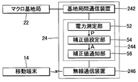
- FIG. 7 is a block diagram of the pico base station 24 in the second embodiment.
- the arithmetic processing unit 244 of each pico base station 24 functions as a power measurement unit 52, a correction value setting unit 54, and a correction value notification unit 56 by executing a program in the storage circuit.
- a configuration in which each function of the arithmetic processing unit 244 is distributed over a plurality of integrated circuits, or a configuration in which a dedicated electronic circuit (DSP) realizes each function may be employed.
- DSP dedicated electronic circuit
- the radio communication device 246 of the pico base station 24 has a function of receiving radio waves from the macro base station 22 forming the macro cell Cm including its own pico cell Cp, in addition to the function of performing radio communication with the mobile terminal 14.
- the power measurement unit 52 measures the power (reception power) P of the radio wave received from the macro base station 22 by the wireless communication device 246.
- the received power P decreases as the distance between the pico base station 24 and the macro base station 22 increases. That is, the received power P functions as an index of the distance between the pico base station 24 and the macro base station 22.
- the correction value setting unit 54 variably sets the correction value A of the pico base station 24 itself according to the received power P measured by the power measurement unit 52. Specifically, the correction value setting unit 54 sets the correction value A to a larger numerical value as the received power P increases (that is, as the distance between the pico base station 24 and the macro base station 22 decreases). For example, the correction value A corresponding to the received power P may be determined with reference to a table in which the value of the correction value A is registered for each value of the received power P, or a predetermined formula using the received power P as a variable. The correction value A may be calculated by the following calculation.
- the correction value A is set to a different value for each pico base station 24. .
- the correction value notification unit 56 sets the correction value setting unit 54 for each mobile terminal 14 located in the pico cell Cp formed by the pico base station 24 itself. The correction value A is notified from the wireless communication device 246.
- the base station selection unit 36 has the radio base station 20 (macro base station) having the maximum received radio wave characteristic value R after processing by the characteristic value correction unit 34 among the plurality of radio base stations 20 that can communicate with the mobile terminal 14.
- Station 22 or pico base station 24 is selected.
- the correction value A is set to a larger value as the pico base station 24 having a larger received power P from the macro base station 22 (that is, the pico base station 24 having a smaller distance from the macro base station 22).
- the picocell Cp is substantially expanded.
- the terminal for the macro base station 22 It is possible to reduce the concentration of connections (that is, equalize the number of terminal connections between the macro base station 22 and the pico base station 24).
- the correction value A is set to a small value for the pico base station 24 at a position where the received power P from the macro base station 22 is small, but the pico base station 24 at a position sufficiently away from the macro base station 22 is Even if the substantial area of the picocell Cp is not expanded so much, the possibility of being selected by the mobile terminal 14 is high.
- each pico base station 24 sets its own correction value A and notifies each mobile terminal 14 thereof.
- the macro base station 22 sets the correction value A for each of the plurality of pico base stations 24 that form the pico cell Cp in its own macro cell Cm.
- FIG. 8 is a block diagram of the macro base station 22 in the third embodiment.
- the arithmetic processing unit 224 of the macro base station 22 executes a program stored in a storage circuit (not shown) to thereby execute a plurality of functions (a speed estimation unit 62, a correction value setting unit 64, a correction).
- a value notification unit 66) is realized.
- a configuration in which each function of the arithmetic processing unit 224 illustrated in FIG. 8 is distributed to a plurality of integrated circuits, or a configuration in which a dedicated electronic circuit (DSP) realizes each function may be employed.
- DSP dedicated electronic circuit
- the speed estimation unit 62 measures the total communication speed T.
- the total communication speed T is an index of the overall communication efficiency between the macro base station 22 and the plurality of pico base stations 24 in the macro cell Cm, and the communication speed of each of the plurality of pico base stations 24 in the macro cell Cm ( Throughput) and the communication speed of the macro base station 22 itself. For example, the information transfer amount per unit time in each pico base station 24 is notified to the macro base station 22 as a communication speed, and the speed estimation unit 62 notifies the communication speed of the macro base station 22 itself and each pico base station 24. The total value with the communication speed to be calculated is calculated as the total communication speed T.
- the correction value setting unit 64 variably sets the correction value A of each pico base station 24 in the macro cell Cm formed by the macro base station 22 according to the total communication speed T. Specifically, the correction value setting unit 64 individually calculates the correction value A for each pico base station 24 so that the total communication speed T increases.
- the correction value notification unit 66 notifies the correction value A set by the correction value setting unit 64 for each pico base station 24 to the pico base station 24 via the inter-base station communication device 222.
- Each pico base station 24 notifies the correction value A notified from the macro base station 22 to each mobile terminal 14 in its pico cell Cp.
- FIG. 9 is a flowchart of an operation in which the macro base station 22 sets and notifies the correction value A of each pico base station 24.
- the process of FIG. 9 is executed in response to an interrupt generated at a predetermined cycle.
- the correction values A (1) to A (N) of a plurality (N) of pico base stations 24 corresponding to the macro base station 22 are updated as appropriate for each processing in FIG.
- the speed estimation unit 62 acquires the communication speed from each of the N pico base stations 24 in the macro cell Cm and measures the current total communication speed T (0) (S20). .
- the correction value setting unit 64 increases the correction value A (n) at the current stage of the target base station 24 (n) by the change amount ⁇ 1 (S22). Then, the speed estimation unit 62 estimates the total communication speed T (n) when the correction value A (n) of the target base station 24 (n) is increased by the change amount ⁇ 1 (S23).
- the method of estimating the total communication speed T (n) is arbitrary. For example, the amount of change in the total communication speed T (n) that is assumed when the correction value A is changed by the change amount ⁇ 1 is used as the pico base station. Every 24 may be obtained in advance statistically or experimentally.
- the speed estimation unit 62 calculates the total communication speed T (n ⁇ 1) calculated in step S23 of the previous correction value setting process (the total communication speed T (0) in step S20 in the first correction value setting process). Is changed by the amount of change prepared for the target base station 24 (n) to calculate the current total communication speed T (n).
- the correction value setting unit 64 uses the total communication speed T (n) calculated in step S23 as the total communication speed T (n-1) calculated in step S23 of the previous correction value setting process (that is, the target base station 24 ( It is determined whether or not the correction value A (n) of n) exceeds the total communication speed when not increasing (S24).
- the first correction value setting process it is determined in step S24 whether or not the total communication speed T (1) calculated in the immediately preceding step S23 exceeds the total communication speed T (0) in step S20.
- the correction value notification unit 66 uses the correction value A (n) changed in step S22 as the base station-to-base station communication device.
- the target base station 24 (n) is notified from 222 (S26). That is, when an increase in the total communication speed T is expected as a result of the increase in the correction value A (n), the increased value is determined as the correction value A (n) of the target base station 24 (n). .
- the correction value setting unit 64 uses the correction value A (n) increased in step S22 as the change amount ⁇ . Decrease by 2 (S25). For example, the change amount ⁇ 2 is set to a value equal to the change amount ⁇ 1 . That is, when the total communication speed T is expected to decrease as a result of increasing the correction value A (n) (S24: NO), the increase in the correction value A (n) in step S22 is cancelled.
- the correction value notification unit 66 notifies the target base station 24 (n) of the correction value A (n) after the process of step S25 from the inter-base station communication device 222 (S26).
- each of the correction values A (1) to A (N) of each pico base station 24 is sequentially updated for each processing of FIG. 9 so that the total communication speed T increases. .
- the operation of the mobile terminal 14 that has received the correction value A (n) from each pico base station 24 is the same as in the first embodiment.
- the macro base station is compared with a configuration in which the pico cell Cp is not expanded, as in the first embodiment. It is possible to alleviate the concentration of terminal connections to the terminal 22. Further, since the correction value A (n) is individually adjusted for each pico base station 24, the concentration of terminal connections with respect to a specific pico base station 24 is alleviated (that is, the number of terminal connections is between each pico base station 24). Is equalized). Particularly in the third embodiment, since the correction value A (n) of each pico base station 24 is set so that the total communication speed T increases, one macro base station 22 and N pico corresponding to the macro base station 22 are set. It is possible to improve the overall communication efficiency with the base station 24.
- the content of the communication load index L in the first embodiment is not limited to the communication traffic of the pico base station 24.
- the total number (number of connected terminals) of the mobile terminals 14 connected to the pico base station 24 may be used as the communication load index L, or communication with the mobile terminal 14 among resources available in the pico base station 24 is actually performed.
- the communication load index L may be a ratio (resource utilization rate) used in
- the resource is, for example, a frequency resource block in OFDMA or a downlink channelization code in CDMA.
- the correction value A is variable according to both the communication load index L exemplified in the first embodiment and the received power P exemplified in the second embodiment (for example, the weighted sum of the communication load index L and the received power P).
- Modification 3 The method of correcting the received radio wave characteristic value R 0 to which the correction value A is applied is changed as appropriate. For example, the received radio wave characteristic value R 0 is multiplied by the correction value A to calculate the corrected received radio wave characteristic value R, or a predetermined mathematical expression using the received radio wave characteristic value R 0 and the correction value A as variables. A configuration in which the received radio wave characteristic value R corrected by calculation is calculated may be employed. The correction value A is calculated by an appropriate method according to the correction method of the received radio wave characteristic value R 0 .
- the pico base station 24 is exemplified as the radio base station 20 that forms the cell C having a small area.
- the type of the radio base station 20 that forms the cell C in the macro cell Cm is arbitrary.
- a micro base station that forms a cell (micro cell) C having a radius of several tens to several hundreds of meters, or a femto base station that forms a cell (femto cell) having a radius of several meters is used as a pico in each of the above forms.
- FIG. A configuration including three or more types of radio base stations 20 having different communication powers may also be employed.
- the mobile communication network 12 includes the radio base station 20 (for example, the macro base station 22 of the embodiment) that forms the first cell, and the second cell having a smaller area than the first cell.
- a communication network including the radio base station 20 to be formed (for example, the pico base station 24 of the embodiment) (in other words, a communication network including a plurality of types of radio base stations 20 having different communication powers) is included.
- DESCRIPTION OF SYMBOLS 100 ... Wireless communication system, 12 ... Mobile communication network, 14 ... Mobile terminal, 142, 226 ... Wireless communication apparatus, 144, 224, 244 ... Arithmetic processing unit, 20 ... Radio base station, 22 ... Macro base station (first radio base station), 222, 242 ... inter-base station communication device, 24 ... pico base station (second radio base station), 246 ... radio communication device (radio communication unit), 32 ... ... characteristic value measuring unit, 34 ... characteristic value correcting unit, 36 ... base station selecting unit, 42 ... load measuring unit, 44, 54, 64 ... correction value setting unit, 46, 56, 66 ... correction value Notification unit, 52... Power measurement unit, 62... Speed estimation unit.
Landscapes
- Engineering & Computer Science (AREA)
- Computer Networks & Wireless Communication (AREA)
- Signal Processing (AREA)
- Mobile Radio Communication Systems (AREA)
Abstract
移動端末は、各無線基地局からの受信電波特性値に応じて接続先の無線基地局を選択する。複数の無線基地局は、マクロ基地局と複数のピコ基地局とを含む。各ピコ基地局は、自身の通信負荷指標を測定または算定する負荷測定部と、自身の受信電波特性値を移動端末にて増加させる補正値を通信負荷指標に応じて可変に設定する補正値設定部と、補正値設定部により設定された補正値を移動端末に通知する補正値通知部とを含む。
Description
本発明は、通信電力が相違する複数種の無線基地局を含む移動通信網において各無線基地局を制御する技術に関する。
通信電力が相違する複数種の無線基地局(例えばマクロ基地局とピコ基地局)を階層的に設置した移動通信網(heterogeneous network)では、通信電力の大きいマクロ基地局が通信電力の小さいピコ基地局と比較してセルサーチやハンドオーバの段階で移動端末の接続先として選択され易い。したがって、通信負荷がマクロ基地局に集中する傾向がある。以上のような通信負荷の集中を緩和するために、例えば非特許文献1には、ピコ基地局が形成するセル(ピコセル)を拡張する技術(range extension)が開示されている。range extensionは、cell range expansionとも呼ばれる。
Aamod Khandekar et al.,"LTE-Advanced:Heterogeneous Networks", Proc. 2010 European Wireless Conference, p.978-p.982, April 2010
非特許文献1のように各ピコセルを拡張する技術によれば、移動端末の接続先としてピコ基地局が選択される機会は確かに増加する。しかし、複数のピコ基地局についてピコセルが同等に拡張されるから、多数の移動端末が集中する位置のピコ基地局ほど移動端末の接続数が増加する。そして、ピコ基地局同士の接続端末数に不均衡が発生すると、移動端末の接続が集中したピコ基地局にて通信速度(スループット)が低下するという問題がある。以上の事情を考慮して、本発明は、通信電力が相違する複数種の無線基地局を含む移動通信網において特定の無線基地局に対する端末接続の集中を緩和して通信効率を向上させることを目的とする。
本発明の第1態様に係る移動通信網は、各無線基地局から受信する電波の特性を示す受信電波特性値を測定または算定して各受信電波特性値に応じた無線基地局を選択する移動端末との間で各々が無線通信可能な複数の無線基地局を具備する移動通信網であって、複数の無線基地局は、第1セルを形成する第1無線基地局と、第1セルよりも面積が小さい第2セルを各々が第1セル内に形成する複数の第2無線基地局とを含み、複数の第2無線基地局の各々は、当該第2無線基地局の通信負荷指標を測定または算定する負荷測定部と、移動端末が当該第2無線基地局から受信する電波の受信電波特性値を当該移動端末にて変更するための補正値を通信負荷指標に応じて可変に設定する要素であって、通信負荷指標が第1閾値を下回る場合に補正値を増加させ、第1閾値よりも大きい第2閾値を通信負荷指標が上回る場合に補正値を減少させる補正値設定部と、補正値設定部により設定された補正値を移動端末に通知する補正値通知部とを含む。
第1態様の移動通信網では、各第2無線基地局が形成する第2セルの実質的な面積(すなわち第2無線基地局の実質的な通信電力)がその第2無線基地局の通信負荷に応じて調整されるから、特定の第2無線基地局に対する端末接続の集中が緩和されるという利点がある。第1態様の具体例は例えば第1実施形態として後述される。なお、本発明は、第1態様の移動通信網において第2無線基地局として採用される無線基地局(例えばピコ基地局24)としても特定され得る。
本発明の第2態様に係る移動通信網は、各無線基地局から受信する電波の特性を示す受信電波特性値を測定または算定して各受信電波特性値に応じた無線基地局を選択する移動端末との間で各々が無線通信可能な複数の無線基地局を具備する移動通信網であって、複数の無線基地局は、第1セルを形成する第1無線基地局と、第1セルよりも面積が小さい第2セルを各々が第1セル内に形成する複数の第2無線基地局とを含み、複数の第2無線基地局の各々は、第1無線基地局と無線通信する無線通信部と、無線通信部による第1無線基地局からの受信電力を測定する電力測定部と、移動端末が当該第2無線基地局から受信する電波の受信電波特性値を当該移動端末にて変更するための補正値を、電力測定部が測定した受信電力に応じて可変に設定する補正値設定部と、補正値設定部が設定した補正値を移動端末に通知する補正値通知部とを含む。
第2態様の移動通信網では、各第2無線基地局が形成する第2セルの実質的な面積がその第2無線基地局と第1無線基地局との距離に応じて調整されるから、第1無線基地局に対する端末接続の集中や特定の第2無線基地局に対する端末接続の集中が緩和されるという利点がある。第2態様の具体例は例えば第2実施形態として後述される。なお、本発明は、第2態様の移動通信網において第2無線基地局として採用される無線基地局としても特定され得る。
本発明の第3態様に係る移動通信網は、各無線基地局から受信する電波の特性を示す受信電波特性値を測定または算定して各受信電波特性値に応じた無線基地局を選択する移動端末との間で各々が無線通信可能な複数の無線基地局を具備する移動通信網であって、複数の無線基地局は、第1セルを形成する第1無線基地局と、第1セルよりも面積が小さい第2セルを各々が第1セル内に形成する複数の第2無線基地局とを含み、第1無線基地局は、当該第1無線基地局と複数の第2無線基地局との通信速度の総計を推定する速度推定部と、移動端末が各第2無線基地局から受信する電波の受信電波特性値を当該移動端末にて変更するための補正値を、当該第1無線基地局と複数の第2無線基地局との通信速度の総計が速度推定部による推定値から上昇するように第2無線基地局毎に可変に設定する補正値設定部と、補正値設定部が各第2無線基地局について設定した各補正値を、当該第2無線基地局を介して移動端末に通知する補正値通知部とを含む。
第3態様の移動通信網では、通信速度の総計が上昇するように補正値が第2無線基地局毎に個別に設定されるから、第1無線基地局と複数の第2無線基地局とを含む全体的な通信効率を向上させながら、第1無線基地局に対する端末接続の集中や特定の第2無線基地局に対する端末接続の集中が緩和されるという利点がある。第3態様の具体例は例えば第3実施形態として後述される。なお、本発明は、第3態様の移動通信網において第1無線基地局として採用される無線基地局としても特定され得る。
<A:第1実施形態>
図1は、本発明の第1実施形態の無線通信システム100のブロック図である。無線通信システム100は、移動通信網12と複数の移動端末14とを具備する。移動通信網12は、音声通話やデータ通信等の無線通信サービスを各移動端末14に提供する通信網であり、相互に接続された複数の無線基地局20を含む。各無線基地局20は、自身が形成するセルC(Cm,Cp)内に在圏する移動端末14と無線通信する。なお、各無線基地局20は、UMTSでのNB(Node B)やUMTS(Universal Mobile Telecommunications System) LTE(Long Term Evolution)でのe-Node Bであり得る。
図1は、本発明の第1実施形態の無線通信システム100のブロック図である。無線通信システム100は、移動通信網12と複数の移動端末14とを具備する。移動通信網12は、音声通話やデータ通信等の無線通信サービスを各移動端末14に提供する通信網であり、相互に接続された複数の無線基地局20を含む。各無線基地局20は、自身が形成するセルC(Cm,Cp)内に在圏する移動端末14と無線通信する。なお、各無線基地局20は、UMTSでのNB(Node B)やUMTS(Universal Mobile Telecommunications System) LTE(Long Term Evolution)でのe-Node Bであり得る。
移動端末14は、例えば携帯電話機(UMTS LTEでのUE(User Equipment))であり、移動通信網12の各無線基地局20を介して他の通信装置(他の移動端末14やサーバ装置)と通信する。なお、無線基地局20と移動端末14との間の無線通信の方式は任意であるが、例えば下り方向にはOFDMA(Orthogonal Frequency Division Multiple Acceess)が採用され、上り方向にはSC-FDMA(Single-Carrier Frequency Division Multiple Access)が採用される。
移動通信網12の複数の無線基地局20は、通信電力が相違するマクロ基地局22とピコ基地局24とに区別される。各マクロ基地局22には複数のピコ基地局24が接続される。なお、図1では便宜的に1個のマクロ基地局22のみを図示したが、実際には相互に接続された多数のマクロ基地局22が配置されて各々に複数のピコ基地局24が接続される。無線通信システム100がLTEに準拠する場合、マクロ基地局22同士の接続およびマクロ基地局22とピコ基地局24との接続には例えばX2インターフェイスが採用される。ただし、RNC(Radio Network Controller)を介して各無線基地局20が通信してもよい。
マクロ基地局(第1無線基地局)22はピコ基地局(第2無線基地局)24と比較して通信電力(最大送信電力)が大きい。したがって、マクロ基地局22が形成するセルC(以下「マクロセルCm」という)の面積はピコ基地局24が形成するセルC(以下「ピコセルCp」という)の面積を上回る。例えば、マクロセル(第1セル)Cmは半径数百メートルから数十キロメートル程度の範囲であり、ピコセル(第2セル)Cpは半径数メートルから数十メートル程度の範囲である。図1に示すように、各マクロ基地局22のマクロセルCmの内側には複数のピコ基地局24が設置される。したがって、マクロセルCm内には複数のピコセルCpが形成される。以上の説明から理解されるように、移動通信網12は、通信電力が相違する複数種の無線基地局20が階層的に配置された通信網(heterogeneous network)である。
図2は、各移動端末14のブロック図である。移動端末14は、無線通信装置142と演算処理装置144とを具備する。なお、音声や画像を出力する出力装置や利用者からの指示を受付ける入力装置等の図示は便宜的に省略されている。
無線通信装置142は、移動端末14自身が在圏するセルCを形成する無線基地局20(マクロ基地局22またはピコ基地局24)と無線通信する通信機器であり、無線基地局20から電波を受信して電気信号に変換する受信回路と、音声信号等の電気信号を電波に変換して送信する送信回路とを含む。また、第1実施形態の無線通信装置142は、移動端末14自身が在圏するピコセルCpを形成するピコ基地局24から補正値A(詳細は後述)を受信する。
演算処理装置144は、記憶回路(図示略)に格納されたプログラムを実行することで複数の機能(特性値測定部32,特性値補正部34,基地局選択部36)を実現する。なお、演算処理装置144の各機能を複数の集積回路に分散した構成や、専用の電子回路(DSP(Digital Signal Processor)が各機能を実現する構成も採用され得る。
特性値測定部32は、無線通信装置142が各無線基地局20から受信した電波の特性値(以下「受信電波特性値」という)R0を測定または算定する。受信電波特性値R0の典型例は受信電力であるが、例えば信号対干渉比(SIR(Signal-to-Interference Ratio)や信号対雑音比(SNR(Signal-to-Noise Ratio))も受信電波特性値R0として利用され得る。
特性値補正部34は、特性値測定部32が各ピコ基地局24について特定した受信電波特性値R0を、無線通信装置142がそのピコ基地局24から受信した補正値Aに応じて補正することで受信電波特性値Rを算定する。具体的には、ピコ基地局24の受信電波特性値R0と補正値Aとの加算値が補正後の受信電波特性値R(R=R0+A)として算定される。すなわち、第1実施形態の補正値Aは、受信電波特性値Rに対するオフセット値を意味する。他方、特性値補正部34は、特性値測定部32がマクロ基地局22について測定した受信電波特性値R0を補正せずに受信電波特性値Rとして確定する。
基地局選択部36は、移動端末14と通信可能な複数の無線基地局20のうち実際に移動端末14が接続すべき無線基地局20(マクロ基地局22またはピコ基地局24)を、各無線基地局20の受信電波特性値Rに応じて選択する。基地局選択部36による無線基地局20の選択は、例えばセルサーチやハンドオーバの段階で実行される。
具体的には、基地局選択部36は、移動端末14と通信可能な複数の無線基地局20のうち、特性値補正部34による処理後の受信電波特性値Rが最大となる無線基地局20を選択する。すなわち、補正値Aによる補正後のピコ基地局24の受信電波特性値R(=R0+A)が最大となる場合にはそのピコ基地局24が移動端末14の接続先として選択され、マクロ基地局22の受信電波特性値R(=R0)が最大となる場合にはそのマクロ基地局22が移動端末14の接続先として選択される。以上の説明から理解されるように、特性値補正部34による受信電波特性値Rの補正(補正値Aの加算)は、ピコ基地局24が形成するピコセルCpを実質的に拡張する(すなわちピコ基地局24の通信電力を実質的に上昇させる)ように作用する。すなわち、図3に示すように、補正値Aが大きいピコ基地局24のピコセルCpほど実質的な面積は拡大する。
例えば、ピコ基地局24の補正前の受信電波特性値R0がマクロ基地局22の受信電波特性値R0を下回る場合でも、補正値Aによる補正後のピコ基地局24の受信電波特性値Rがマクロ基地局22の受信電波特性値Rを上回る場合にはピコ基地局24が移動端末14の接続先として選択される。また、補正前の受信電波特性値R0が相等しい複数のピコ基地局24が移動端末14と通信可能な場合には、補正値Aが最大のピコ基地局24が移動端末14の接続先として選択される。すなわち、図3に示すように、補正値Aが大きいピコ基地局24ほど移動端末14の接続先として選択され易い。
図4は、マクロ基地局22のブロック図である。各マクロ基地局22は、基地局間通信装置222と演算処理装置224と無線通信装置226とを具備する。基地局間通信装置222は、移動通信網12内の他の無線基地局20(マクロ基地局22またはピコ基地局24)と通信する。無線通信装置226は、マクロ基地局22自身が形成するマクロセルCm内に在圏する移動端末14と無線通信する通信機器であり、移動端末14から電波を受信して電気信号に変換する受信回路と、移動端末14に提供すべき情報を電波に変換して送信する送信回路とを含む。演算処理装置224は、無線基地局20の全体的な動作を制御する。
図5は、ピコ基地局24のブロック図である。各ピコ基地局24は、基地局間通信装置242と演算処理装置244と無線通信装置(無線通信部)246とを具備する。基地局間通信装置242は、ピコ基地局24自身が接続されたマクロ基地局22と通信する。無線通信装置246は、ピコ基地局24自身が形成するピコセルCp内に在圏する移動端末14と無線通信する通信機器であり、無線通信装置226と同様に、移動端末14から電波を受信して電気信号に変換する受信回路と、移動端末14に提供すべき情報を電波に変換して送信する送信回路とを含む。
演算処理装置244は、ピコ基地局24の全体的な動作を制御する。第1実施形態の演算処理装置244は、記憶回路(図示略)に格納されたプログラムを実行することで複数の機能(負荷測定部42,補正値設定部44,補正値通知部46)を実現する。なお、演算処理装置244の各機能を複数の集積回路に分散した構成や、専用の電子回路(DSP)が各機能を実現する構成も採用され得る。
負荷測定部42は、ピコ基地局24自身の通信負荷を示す指標値(以下「通信負荷指標」という)Lを測定または算定する。第1実施形態の通信負荷指標Lは通信トラフィックを示す。例えば、ピコ基地局24が形成するピコセルCp内の移動端末14からの発呼数とピコセルCp内の移動端末14に対する着呼数との単位時間内の合計値、あるいはピコ基地局24が単位時間内で中継するパケットの総数が、通信トラヒックとして通信負荷指標Lで表現される。
補正値設定部44は、負荷測定部42が測定した通信負荷指標Lに応じてピコ基地局24自身の補正値Aを可変に設定する。具体的には、補正値設定部44は、通信負荷指標Lが示す通信負荷が大きいほど補正値Aを小さい数値に設定する。例えば、通信負荷指標Lの数値毎に補正値Aの数値が登録されたテーブルを参照して現在の通信負荷指標Lに対応する補正値Aを決定してもよいし、通信負荷指標Lを変数とする所定の数式の演算で補正値Aを算定してもよい。通信負荷指標Lはピコ基地局24毎に相違するから、補正値Aはピコ基地局24毎に相異なる数値に設定され得る。補正値通知部46は、ピコ基地局24自身が形成するピコセルCp内に在圏する各移動端末14に対し、補正値設定部44が設定した補正値Aを無線通信装置246から通知する。前述の通り、補正値Aは各移動端末14にて無線基地局20の選択に利用される。
図6は、各ピコ基地局24の演算処理装置244が補正値Aを設定および通知する動作のフローチャートである。例えば所定の周期で発生する割込を契機として図6の処理が実行され、処理毎に補正値Aが更新される。図6の処理が開始すると、負荷測定部42は、ピコ基地局24自身の現在の通信負荷指標Lを測定または算定する(S10)。補正値設定部44は、以下に詳述するように、ピコ基地局24自身の通信負荷指標Lが所定の範囲内(Lth1≦L≦Lth2)の数値に近付くように補正値Aを更新する(S11~S14)。
補正値設定部44は、負荷測定部42が測定した通信負荷指標Lが所定の閾値Lth1を下回るか否かを判定する(S11)。通信負荷指標Lが第1閾値Lth1を下回る場合(S11:YES)、補正値設定部44は、現段階の補正値Aに所定値Δ1を加算した数値を更新後の補正値A(A=A+Δ1)として算定する(S12)。補正値通知部46は、更新後の補正値Aを無線通信装置246からピコセルCp内の各移動端末14に通知して図6の処理を終了する(S15)。以上の動作の結果、通信負荷が小さい(通信負荷指標Lが閾値Lth1を下回る)ピコ基地局24は、補正値Aが増加することで移動端末14の接続先として選択され易くなる。
他方、通信負荷指標Lが所定の第1閾値Lth1を上回る場合(S11:NO)、補正値設定部44は、通信負荷指標Lが所定の第2閾値Lth2を上回るか否かを判定する(S13)。閾値Lth2は、閾値Lth1を上回る所定値である。通信負荷指標Lが閾値Lth2を上回る場合(S13:YES)、補正値設定部44は、現段階の補正値Aから所定値Δ2を減算した数値を更新後の補正値A(A=A-Δ2)として算定する(S14)。所定値Δ2は、例えば所定値Δ1と等しい数値に設定される。補正値通知部46は、更新後の補正値AをピコセルCp内の各移動端末14に通知して図6の処理を終了する(S15)。したがって、通信負荷が大きい(通信負荷指標Lが閾値Lth2を上回る)ピコ基地局24は、補正値Aが減少することで移動端末14の接続先として選択され難くなる。
他方、通信負荷指標Lが第1閾値Lth1と第2閾値Lth2との間の範囲内にある場合(S13:NO)、補正値通知部46は、現段階の補正値A(すなわち前回の処理時と同じ補正値A)を各移動端末14に通知して図6の処理を終了する(S15)。以上の説明から理解されるように、各ピコ基地局24から移動端末14に通知される補正値Aはピコ基地局24毎の通信状況(通信負荷指標L)に応じて刻々と変化する。すなわち、通信負荷が小さいピコ基地局24ほど、ピコセルCpが実質的に拡張して移動端末14に選択され易くなる。
以上に説明したように、第1実施形態では、各ピコ基地局24のピコセルCpが実質的に拡張されるから、ピコセルCpを拡張しないシステムと比較して、マクロ基地局22に対する端末接続の集中を緩和する(すなわち、端末接続数をマクロ基地局22とピコ基地局24とで均等化する)ことが可能である。また、補正値Aをピコ基地局24毎に設定することで各ピコセルCpの実質的な面積がピコ基地局24毎の通信負荷に応じて個別に調整されるから、特定のピコ基地局24に対する端末接続の集中が緩和される(すなわち、端末接続数が各ピコ基地局24間で均等化される)という利点がある。
第1実施形態のバリエーションとして、例えば通信負荷指標Lを1種類の閾値Lthのみと比較し、通信負荷指標Lが閾値Lthを下回る場合には補正値Aを増加させるとともに閾値Lthを上回る場合には補正値Aを減少させることも想定され得る。しかし、このバリエーションでは、通信負荷の変動に応じて補正値Aが過度に頻繁に変化する(すなわちピコセルCpの実質的な面積が頻繁に変化する)から、移動端末14の接続先を変更する頻度が増加するという問題がある。第1実施形態では、通信負荷指標Lが閾値Lth1から閾値Lth2までの範囲内にある場合には補正値Aが変化しないから、各ピコセルCpの実質的な面積の変動は抑制される。したがって、第1実施形態によれば、単一の閾値Lthのみを利用するバリエーションと比較して移動端末14とピコ基地局24との通信が安定化されるという利点がある。
<B:第2実施形態>
本発明の第2実施形態を以下に説明する。なお、以下に例示する各態様において作用や機能が第1実施形態と同等である要素については、以上の説明で参照した符号を流用して各々の詳細な説明を適宜に省略する。
本発明の第2実施形態を以下に説明する。なお、以下に例示する各態様において作用や機能が第1実施形態と同等である要素については、以上の説明で参照した符号を流用して各々の詳細な説明を適宜に省略する。
図7は、第2実施形態におけるピコ基地局24のブロック図である。図7に示すように、各ピコ基地局24の演算処理装置244は、記憶回路内のプログラムを実行することで電力測定部52と補正値設定部54と補正値通知部56として機能する。なお、演算処理装置244の各機能を複数の集積回路に分散した構成や、専用の電子回路(DSP)が各機能を実現する構成も採用され得る。
ピコ基地局24の無線通信装置246は、移動端末14と無線通信する機能に加えて、自身のピコセルCpを含むマクロセルCmを形成するマクロ基地局22から電波を受信する機能を備える。電力測定部52は、無線通信装置246がマクロ基地局22から受信した電波の電力(受信電力)Pを測定する。ピコ基地局24とマクロ基地局22との距離が大きいほど受信電力Pは減少する。すなわち、受信電力Pは、ピコ基地局24とマクロ基地局22との距離の指標として機能する。
補正値設定部54は、電力測定部52が測定した受信電力Pに応じてピコ基地局24自身の補正値Aを可変に設定する。具体的には、補正値設定部54は、受信電力Pが大きいほど(すなわちピコ基地局24とマクロ基地局22との距離が小さいほど)補正値Aを大きい数値に設定する。例えば、受信電力Pの数値毎に補正値Aの数値が登録されたテーブルを参照して受信電力Pに対応する補正値Aを決定してもよいし、受信電力Pを変数とする所定の数式の演算で補正値Aを算定してもよい。受信電力Pはマクロ基地局22との距離(ピコ基地局24の設置位置)に応じてピコ基地局24毎に相違するから、補正値Aはピコ基地局24毎に相異なる数値に設定される。補正値通知部56は、第1実施形態の補正値通知部46と同様に、ピコ基地局24自身が形成するピコセルCp内に在圏する各移動端末14に対し、補正値設定部54が設定した補正値Aを無線通信装置246から通知する。
移動端末14の動作は第1実施形態と同様である。すなわち、基地局選択部36は、移動端末14と通信可能な複数の無線基地局20のうち、特性値補正部34による処理後の受信電波特性値Rが最大となる無線基地局20(マクロ基地局22またはピコ基地局24)を選択する。以上の説明から理解されるように、マクロ基地局22からの受信電力Pが大きいピコ基地局24(すなわちマクロ基地局22との距離が小さいピコ基地局24)ほど、補正値Aが大きい数値に設定されてピコセルCpが実質的に拡張される。
マクロ基地局22に近いピコ基地局24のピコセルCp内には受信電力Pの高い電波がマクロ基地局22から到達するから、ピコ基地局24の受信電波特性値R0を補正しないシステムでは、移動端末14がピコセルCp内に位置する場合でもマクロ基地局22が接続先として選択される可能性が高い。第2実施形態によれば、マクロ基地局22との距離が小さいピコ基地局24ほど、補正値Aが大きい数値に設定されてピコセルCpが実質的に拡張されるから、マクロ基地局22に対する端末接続の集中を緩和する(すなわち、端末接続数をマクロ基地局22とピコ基地局24とで均等化する)ことが可能である。なお、マクロ基地局22からの受信電力Pが小さい位置のピコ基地局24については補正値Aが小さい数値に設定されるが、マクロ基地局22から充分に離れた位置のピコ基地局24は、ピコセルCpの実質的な面積をそれほど拡張しなくても移動端末14により選択される可能性は高い。
<C:第3実施形態>
第1実施形態および第2実施形態では、各ピコ基地局24が自身の補正値Aを設定して各移動端末14に通知した。第3実施形態では、マクロ基地局22が、自身のマクロセルCm内にピコセルCpを形成する複数のピコ基地局24の各々について補正値Aを設定する。
第1実施形態および第2実施形態では、各ピコ基地局24が自身の補正値Aを設定して各移動端末14に通知した。第3実施形態では、マクロ基地局22が、自身のマクロセルCm内にピコセルCpを形成する複数のピコ基地局24の各々について補正値Aを設定する。
図8は、第3実施形態におけるマクロ基地局22のブロック図である。図8に示すように、マクロ基地局22の演算処理装置224は、記憶回路(図示略)に格納されたプログラムを実行することで複数の機能(速度推定部62,補正値設定部64,補正値通知部66)を実現する。なお、図8に図示された演算処理装置224の各機能を複数の集積回路に分散した構成や、専用の電子回路(DSP)が各機能を実現する構成も採用され得る。
速度推定部62は、総通信速度Tを測定する。総通信速度Tは、マクロ基地局22とそのマクロセルCm内の複数のピコ基地局24との全体的な通信効率の指標であり、マクロセルCm内の複数のピコ基地局24の各々の通信速度(スループット)とマクロ基地局22自身の通信速度との総計に相当する。例えば、各ピコ基地局24での単位時間毎の情報転送量が通信速度としてマクロ基地局22に通知され、速度推定部62は、マクロ基地局22自身の通信速度と各ピコ基地局24から通知される通信速度との合計値を総通信速度Tとして算定する。
補正値設定部64は、マクロ基地局22が形成するマクロセルCm内の各ピコ基地局24の補正値Aを総通信速度Tに応じて可変に設定する。具体的には、補正値設定部64は、総通信速度Tが上昇するようにピコ基地局24毎に補正値Aを個別に算定する。補正値通知部66は、各ピコ基地局24について補正値設定部64が設定した補正値Aを、基地局間通信装置222を介してそのピコ基地局24に通知する。各ピコ基地局24は、マクロ基地局22から通知された補正値Aを自身のピコセルCp内の各移動端末14に通知する。
図9は、マクロ基地局22が各ピコ基地局24の補正値Aを設定および通知する動作のフローチャートである。例えば所定の周期で発生する割込を契機として図9の処理が実行される。マクロ基地局22に対応する複数(N個)のピコ基地局24の補正値A(1)~A(N)が図9の処理毎に適宜に更新される。図9の処理が開始すると、速度推定部62は、マクロセルCm内のN個のピコ基地局24の各々から通信速度を取得して現段階の総通信速度T(0)を測定する(S20)。
補正値設定部64は、N個のピコ基地局24のうち第n番目(n=1~N)の1個のピコ基地局24(以下「対象基地局24(n)」という)を選択する(S21)。マクロセルCm内のN個のピコ基地局24の各々を対象基地局24(n)として、以下のステップS22からステップS26の処理(以下「補正値設定処理」という)が順次に実行される(S27:NO)。
補正値設定処理が開始すると、補正値設定部64は、対象基地局24(n)の現段階の補正値A(n)を変化量Δ1だけ増加させる(S22)。そして、速度推定部62は、対象基地局24(n)の補正値A(n)を変化量Δ1だけ増加させた場合の総通信速度T(n)を推定する(S23)。総通信速度T(n)の推定の方法は任意であるが、例えば、補正値Aを変化量Δ1だけ変化させた場合に想定される総通信速度T(n)の変化量をピコ基地局24毎に統計的または実験的に事前に得ておけばよい。すなわち、速度推定部62は、前回の補正値設定処理のステップS23で算定した総通信速度T(n-1)(第1回目の補正値設定処理ではステップS20の総通信速度T(0))を、対象基地局24(n)について用意された変化量だけ変化させることで、現段階の総通信速度T(n)を算定する。
補正値設定部64は、ステップS23で算定した総通信速度T(n)が、前回の補正値設定処理のステップS23で算定した総通信速度T(n-1)(すなわち、対象基地局24(n)の補正値A(n)を増加させない場合の総通信速度)を上回るか否かを判定する(S24)。なお、第1回目の補正値設定処理では、直前のステップS23で算定した総通信速度T(1)がステップS20の総通信速度T(0)を上回るか否かがステップS24で判定される。ステップS24の判定の結果が肯定である場合(T(n)>T(n-1))、補正値通知部66は、ステップS22で変化させた補正値A(n)を基地局間通信装置222から対象基地局24(n)に通知する(S26)。すなわち、補正値A(n)の増加の結果として総通信速度Tの上昇が見込まれる場合には、その増加後の数値が対象基地局24(n)の補正値A(n)として確定される。
他方、ステップS24の判定の結果が否定である場合(T(n)≦T(n-1))、補正値設定部64は、ステップS22で増加させた補正値A(n)を変化量Δ2だけ減少させる(S25)。変化量Δ2は、例えば変化量Δ1と等しい数値に設定される。すなわち、補正値A(n)を増加させた結果として総通信速度Tの低下が見込まれる場合(S24:NO)、ステップS22での補正値A(n)の増加が取り消される。補正値通知部66は、ステップS25の処理後の補正値A(n)を基地局間通信装置222から対象基地局24(n)に通知する(S26)。
マクロ基地局22のマクロセルCm内に配置されたN個のピコ基地局24の各々について以上の補正値設定処理を実行した時点で図9の処理が終了する(S27:YES)。以上の説明から理解されるように、総通信速度Tが上昇するように各ピコ基地局24の補正値A(1)~A(N)の各々が図9の処理毎に順次に更新される。補正値A(n)を各ピコ基地局24から受信した移動端末14の動作は第1実施形態と同様である。
第3実施形態では、各ピコ基地局24のピコセルCpが補正値Aに応じて実質的に拡張されるから、第1実施形態と同様に、ピコセルCpを拡張しない構成と比較してマクロ基地局22に対する端末接続の集中を緩和することが可能である。また、補正値A(n)がピコ基地局24毎に個別に調整されるから、特定のピコ基地局24に対する端末接続の集中が緩和される(すなわち、端末接続数が各ピコ基地局24間で均等化される)という利点がある。特に第3実施形態では、総通信速度Tが上昇するように各ピコ基地局24の補正値A(n)が設定されるから、1個のマクロ基地局22とこれに対応するN個のピコ基地局24との全体にわたる通信効率を向上させることが可能である。
<D:変形例>
以上の形態には様々な変形が加えられる。具体的な変形の態様を以下に例示する。以下の例示から任意に選択された2以上の態様は適宜に併合され得る。
以上の形態には様々な変形が加えられる。具体的な変形の態様を以下に例示する。以下の例示から任意に選択された2以上の態様は適宜に併合され得る。
(1)変形例1
第1実施形態における通信負荷指標Lの内容はピコ基地局24の通信トラフィックに限定されない。例えば、ピコ基地局24に接続している移動端末14の総数(接続端末数)を通信負荷指標Lとしてもよいし、ピコ基地局24で利用可能なリソースのうち実際に移動端末14との通信で使用されている割合(リソース利用率)を通信負荷指標Lとしてもよい。リソースは、例えばOFDMAにおける周波数リソースブロックやCDMAにおける下りリンクのチャネライゼーションコードである。
第1実施形態における通信負荷指標Lの内容はピコ基地局24の通信トラフィックに限定されない。例えば、ピコ基地局24に接続している移動端末14の総数(接続端末数)を通信負荷指標Lとしてもよいし、ピコ基地局24で利用可能なリソースのうち実際に移動端末14との通信で使用されている割合(リソース利用率)を通信負荷指標Lとしてもよい。リソースは、例えばOFDMAにおける周波数リソースブロックやCDMAにおける下りリンクのチャネライゼーションコードである。
(2)変形例2
以上に例示した各形態は適宜に併合され得る。例えば、第1実施形態で例示した通信負荷指標Lと第2実施形態で例示した受信電力Pとの双方(例えば通信負荷指標Lと受信電力Pとの加重和)に応じて補正値Aが可変に設定される。
以上に例示した各形態は適宜に併合され得る。例えば、第1実施形態で例示した通信負荷指標Lと第2実施形態で例示した受信電力Pとの双方(例えば通信負荷指標Lと受信電力Pとの加重和)に応じて補正値Aが可変に設定される。
(3)変形例3
補正値Aを適用した受信電波特性値R0の補正の方法は適宜に変更される。例えば、受信電波特性値R0に補正値Aを乗算することで補正後の受信電波特性値Rを算定する構成や、受信電波特性値R0と補正値Aとを変数とする所定の数式の演算で補正後の受信電波特性値Rを算定する構成が採用され得る。受信電波特性値R0の補正の方法に応じた適切な方法で補正値Aが算定される。
補正値Aを適用した受信電波特性値R0の補正の方法は適宜に変更される。例えば、受信電波特性値R0に補正値Aを乗算することで補正後の受信電波特性値Rを算定する構成や、受信電波特性値R0と補正値Aとを変数とする所定の数式の演算で補正後の受信電波特性値Rを算定する構成が採用され得る。受信電波特性値R0の補正の方法に応じた適切な方法で補正値Aが算定される。
(4)変形例4
前述の各形態では、面積が小さいセルCを形成する無線基地局20としてピコ基地局24を例示したが、マクロセルCm内にセルCを形成する無線基地局20の種類は任意である。例えば、半径数十メートルから数百メートル程度のセル(マイクロセル)Cを形成するマイクロ基地局や、半径数メートル程度のセル(フェムトセル)を形成するフェムト基地局を、以上の各形態におけるピコ基地局24の代わりに採用してもよい。また、通信電力が相違する3種類以上の無線基地局20を含む構成も採用され得る。以上の説明から理解されるように、移動通信網12は、第1セルを形成する無線基地局20(例えば実施形態のマクロ基地局22)と、第1セルよりも面積が小さい第2セルを形成する無線基地局20(例えば実施形態のピコ基地局24)とを含む通信網(換言すると、通信電力が相違する複数種の無線基地局20を含む通信網)として包括される。
前述の各形態では、面積が小さいセルCを形成する無線基地局20としてピコ基地局24を例示したが、マクロセルCm内にセルCを形成する無線基地局20の種類は任意である。例えば、半径数十メートルから数百メートル程度のセル(マイクロセル)Cを形成するマイクロ基地局や、半径数メートル程度のセル(フェムトセル)を形成するフェムト基地局を、以上の各形態におけるピコ基地局24の代わりに採用してもよい。また、通信電力が相違する3種類以上の無線基地局20を含む構成も採用され得る。以上の説明から理解されるように、移動通信網12は、第1セルを形成する無線基地局20(例えば実施形態のマクロ基地局22)と、第1セルよりも面積が小さい第2セルを形成する無線基地局20(例えば実施形態のピコ基地局24)とを含む通信網(換言すると、通信電力が相違する複数種の無線基地局20を含む通信網)として包括される。
100……無線通信システム、12……移動通信網、14……移動端末、142,226……無線通信装置、144,224,244……演算処理装置、20……無線基地局、22……マクロ基地局(第1無線基地局)、222,242……基地局間通信装置、24……ピコ基地局(第2無線基地局)、246……無線通信装置(無線通信部)、32……特性値測定部、34……特性値補正部、36……基地局選択部、42……負荷測定部、44,54,64……補正値設定部、46,56,66……補正値通知部、52……電力測定部、62……速度推定部。
Claims (7)
- 各無線基地局から受信する電波の特性を示す受信電波特性値を測定または算定して各受信電波特性値に応じた無線基地局を選択する移動端末との間で各々が無線通信可能な複数の無線基地局を具備する移動通信網であって、
前記複数の無線基地局は、第1セルを形成する第1無線基地局と、前記第1セルよりも面積が小さい第2セルを各々が前記第1セル内に形成する複数の第2無線基地局とを含み、
前記複数の第2無線基地局の各々は、
当該第2無線基地局の通信負荷指標を測定または算定する負荷測定部と、
前記移動端末が当該第2無線基地局から受信する電波の受信電波特性値を当該移動端末にて変更するための補正値を前記通信負荷指標に応じて可変に設定する要素であって、前記通信負荷指標が第1閾値を下回る場合に前記補正値を増加させ、前記第1閾値よりも大きい第2閾値を前記通信負荷指標が上回る場合に前記補正値を減少させる補正値設定部と、
前記補正値設定部により設定された補正値を前記移動端末に通知する補正値通知部とを含む
移動通信網。 - 前記複数の第2無線基地局の各々は、
前記第1無線基地局と無線通信する無線通信部と、
前記無線通信部による前記第1無線基地局からの受信電力を測定する電力測定部とを更に具備し、
前記補正値設定部は、当該第2無線基地局の受信電波特性値を前記移動端末にて増加させる補正値を、前記負荷測定部が測定した通信負荷指標と前記電力測定部が測定した前記受信電力とに応じて可変に設定する
請求項1の移動通信網。 - 各無線基地局から受信する電波の特性を示す受信電波特性値を測定または算定して各受信電波特性値に応じた無線基地局を選択する移動端末との間で各々が無線通信可能な複数の無線基地局を具備する移動通信網であって、
前記複数の無線基地局は、第1セルを形成する第1無線基地局と、前記第1セルよりも面積が小さい第2セルを各々が前記第1セル内に形成する複数の第2無線基地局とを含み、
前記複数の第2無線基地局の各々は、
前記第1無線基地局と無線通信する無線通信部と、
前記無線通信部による前記第1無線基地局からの受信電力を測定する電力測定部と、
前記移動端末が当該第2無線基地局から受信する電波の受信電波特性値を当該移動端末にて変更するための補正値を、前記電力測定部が測定した前記受信電力に応じて可変に設定する補正値設定部と、
前記補正値設定部が設定した補正値を前記移動端末に通知する補正値通知部とを含む
移動通信網。 - 各無線基地局から受信する電波の特性を示す受信電波特性値を測定または算定して各受信電波特性値に応じた無線基地局を選択する移動端末との間で各々が無線通信可能な複数の無線基地局を具備する移動通信網であって、
前記複数の無線基地局は、第1セルを形成する第1無線基地局と、前記第1セルよりも面積が小さい第2セルを各々が前記第1セル内に形成する複数の第2無線基地局とを含み、
前記第1無線基地局は、
当該第1無線基地局と前記複数の第2無線基地局との通信速度の総計を推定する速度推定部と、
前記移動端末が前記各第2無線基地局から受信する電波の受信電波特性値を当該移動端末にて変更するための補正値を、当該第1無線基地局と前記複数の第2無線基地局との通信速度の総計が前記速度推定部による推定値から上昇するように前記第2無線基地局毎に可変に設定する補正値設定部と、
前記補正値設定部が前記各第2無線基地局について設定した各補正値を、当該第2無線基地局を介して前記移動端末に通知する補正値通知部とを含む
移動通信網。 - 各無線基地局から受信する電波の特性を示す受信電波特性値を測定または算定して各受信電波特性値に応じた無線基地局を選択する移動端末との間で無線通信可能であり、第1セルを形成する第1無線基地局と通信するとともに前記第1セルよりも面積が小さい第2セルを前記第1セル内に形成する無線基地局であって、
当該第2無線基地局の通信負荷指標を測定または算定する負荷測定部と、
前記移動端末が当該第2無線基地局から受信する電波の受信電波特性値を当該移動端末にて変更するための補正値を前記通信負荷指標に応じて可変に設定する要素であって、前記通信負荷指標が第1閾値を下回る場合に前記補正値を増加させ、前記第1閾値よりも大きい第2閾値を前記通信負荷指標が上回る場合に前記補正値を減少させる補正値設定部と、
前記補正値設定部により設定された補正値を前記移動端末に通知する補正値通知部と
を具備する無線基地局。 - 各無線基地局から受信する電波の特性を示す受信電波特性値を測定または算定して各受信電波特性値に応じた無線基地局を選択する移動端末との間で無線通信可能であり、第1セルを形成する第1無線基地局と通信するとともに前記第1セルよりも面積が小さい第2セルを前記第1セル内に形成する無線基地局であって、
前記第1無線基地局と無線通信する無線通信部と、
前記無線通信部による前記第1無線基地局からの受信電力を測定する電力測定部と、
前記移動端末が当該第2無線基地局から受信する電波の受信電波特性値を当該移動端末にて変更するための補正値を、前記電力測定部が測定した前記受信電力に応じて可変に設定する補正値設定部と、
前記補正値設定部が設定した補正値を前記移動端末に通知する補正値通知部と
を具備する無線基地局。 - 各無線基地局から受信する電波の特性を示す受信電波特性値を測定または算定して各受信電波特性値に応じた無線基地局を選択する移動端末との間で各々が無線通信可能な第1セルを形成するとともに、第1セルよりも面積が小さい第2セルを各々が前記第1セル内に形成する複数の第2無線基地局の各々と通信する無線基地局であって、
当該第1無線基地局と前記複数の第2無線基地局との通信速度の総計を推定する速度推定部と、
前記移動端末が前記各第2無線基地局から受信する電波の受信電波特性値を当該移動端末にて変更するための補正値を、当該第1無線基地局と前記複数の第2無線基地局との通信速度の総計が前記速度推定部による推定値から上昇するように前記第2無線基地局毎に可変に設定する補正値設定部と、
前記補正値設定部が前記各第2無線基地局について設定した各補正値を、当該第2無線基地局を介して前記移動端末に通知する補正値通知部と
を具備する無線基地局。
Priority Applications (2)
| Application Number | Priority Date | Filing Date | Title |
|---|---|---|---|
| US13/990,983 US20130336151A1 (en) | 2010-12-01 | 2011-11-16 | Mobile communications network and radio base station |
| EP11844501.4A EP2648458A1 (en) | 2010-12-01 | 2011-11-16 | Mobile communications network and wireless base station |
Applications Claiming Priority (2)
| Application Number | Priority Date | Filing Date | Title |
|---|---|---|---|
| JP2010268166A JP5465162B2 (ja) | 2010-12-01 | 2010-12-01 | 移動通信網および無線基地局 |
| JP2010-268166 | 2010-12-01 |
Publications (1)
| Publication Number | Publication Date |
|---|---|
| WO2012073697A1 true WO2012073697A1 (ja) | 2012-06-07 |
Family
ID=46171644
Family Applications (1)
| Application Number | Title | Priority Date | Filing Date |
|---|---|---|---|
| PCT/JP2011/076424 Ceased WO2012073697A1 (ja) | 2010-12-01 | 2011-11-16 | 移動通信網および無線基地局 |
Country Status (4)
| Country | Link |
|---|---|
| US (1) | US20130336151A1 (ja) |
| EP (1) | EP2648458A1 (ja) |
| JP (1) | JP5465162B2 (ja) |
| WO (1) | WO2012073697A1 (ja) |
Cited By (4)
| Publication number | Priority date | Publication date | Assignee | Title |
|---|---|---|---|---|
| JP2020148536A (ja) * | 2019-03-12 | 2020-09-17 | パナソニックIpマネジメント株式会社 | 位置推定装置および位置推定システム |
| WO2020184674A1 (ja) * | 2019-03-12 | 2020-09-17 | パナソニックIpマネジメント株式会社 | 位置推定システム、位置推定装置、および位置推定方法 |
| JP2020161882A (ja) * | 2019-03-25 | 2020-10-01 | パナソニックIpマネジメント株式会社 | 位置推定システム、位置推定装置、および位置推定方法 |
| JP2020165900A (ja) * | 2019-03-29 | 2020-10-08 | パナソニックIpマネジメント株式会社 | 位置推定装置、位置推定システム、および位置推定方法 |
Families Citing this family (5)
| Publication number | Priority date | Publication date | Assignee | Title |
|---|---|---|---|---|
| JP5855377B2 (ja) * | 2011-07-21 | 2016-02-09 | 株式会社Nttドコモ | 無線通信システム、無線基地局および通信制御方法 |
| WO2014044310A1 (en) * | 2012-09-20 | 2014-03-27 | Telefonaktiebolaget L M Ericsson (Publ) | Method and network node for improving resource utilization of a radio cell |
| CN103037440B (zh) * | 2012-12-13 | 2016-03-02 | 北京北方烽火科技有限公司 | 一种移动负载均衡方法及装置 |
| JPWO2015022952A1 (ja) | 2013-08-13 | 2017-03-02 | 日本電気株式会社 | 無線パラメータ制御装置、無線基地局、無線通信システム、無線パラメータ制御方法、およびプログラム |
| WO2015051837A1 (en) * | 2013-10-09 | 2015-04-16 | Telefonaktiebolaget L M Ericsson (Publ) | Sounding reference signal based small cell activity control |
Citations (3)
| Publication number | Priority date | Publication date | Assignee | Title |
|---|---|---|---|---|
| JP2005136750A (ja) * | 2003-10-30 | 2005-05-26 | Kyocera Corp | 基地局装置及び制御局装置 |
| JP2007520170A (ja) * | 2004-01-27 | 2007-07-19 | テルコーディア テクノロジーズ インコーポレイテッド | Cdmaネットワークパラメータの動的自動最適化のための方法およびシステム |
| WO2010061628A1 (ja) * | 2008-11-28 | 2010-06-03 | パナソニック株式会社 | 無線通信基地局装置及び総送信電力制御方法 |
Family Cites Families (5)
| Publication number | Priority date | Publication date | Assignee | Title |
|---|---|---|---|---|
| JP2006179965A (ja) * | 2004-10-25 | 2006-07-06 | Nec Corp | 無線ネットワーク制御方法、無線通信システム、基地局制御装置 |
| CN101836487B (zh) * | 2007-10-22 | 2015-01-14 | 日本电气株式会社 | 无线通信系统、基站、无线电资源管理方法和基站控制程序 |
| US20090135754A1 (en) * | 2007-11-27 | 2009-05-28 | Qualcomm Incorporated | Interference management in a wireless communication system using overhead channel power control |
| JP5156498B2 (ja) * | 2008-06-18 | 2013-03-06 | 株式会社エヌ・ティ・ティ・ドコモ | 基地局及び移動通信方法 |
| US8295874B2 (en) * | 2009-06-10 | 2012-10-23 | Motorola Mobility Llc | Femto-cell power control using idle-mode user equipment in a cellular communication system |
-
2010
- 2010-12-01 JP JP2010268166A patent/JP5465162B2/ja not_active Expired - Fee Related
-
2011
- 2011-11-16 EP EP11844501.4A patent/EP2648458A1/en not_active Withdrawn
- 2011-11-16 WO PCT/JP2011/076424 patent/WO2012073697A1/ja not_active Ceased
- 2011-11-16 US US13/990,983 patent/US20130336151A1/en not_active Abandoned
Patent Citations (3)
| Publication number | Priority date | Publication date | Assignee | Title |
|---|---|---|---|---|
| JP2005136750A (ja) * | 2003-10-30 | 2005-05-26 | Kyocera Corp | 基地局装置及び制御局装置 |
| JP2007520170A (ja) * | 2004-01-27 | 2007-07-19 | テルコーディア テクノロジーズ インコーポレイテッド | Cdmaネットワークパラメータの動的自動最適化のための方法およびシステム |
| WO2010061628A1 (ja) * | 2008-11-28 | 2010-06-03 | パナソニック株式会社 | 無線通信基地局装置及び総送信電力制御方法 |
Non-Patent Citations (4)
| Title |
|---|
| AAMOD KHANDEKAR ET AL.: "LTE-Advanced: Heterogeneous Networks", PROC. 2010 EUROPEAN WIRELESS CONFERENCE, April 2010 (2010-04-01), pages 978 - 982 |
| FURUMASA KUSANO ET AL.: "Efficient Operation of Small and Low-Power Base Station in LTE/LTE- Advanced Heterogeneous Network", IEICE TECHNICAL REPORT, vol. 110, no. 251, 20 October 2010 (2010-10-20), pages 125 - 130, XP008170498 * |
| HIDENORI MATSUO. ET AL.: "LTE-Advanced Priority cell selection based on interference in LTE- Advanced heterogeneous network", IEICE TECHNICAL REPORT, vol. 111, no. 9, 14 April 2011 (2011-04-14), pages 1 - 6, XP008170499 * |
| PENG TIAN ET AL.: "An Adaptive Bias Configuration Strategy for Range Extension in LTE-Advanced Heterogeneous Networks", PROCEEDINGS OF ICCTA2011 (INTERNATIONAL CONFERENCE ON COMMUNICATION TECHNOLOGY AND APPLICATION 2011), 14 October 2011 (2011-10-14), pages 1 - 5, XP055081299 * |
Cited By (7)
| Publication number | Priority date | Publication date | Assignee | Title |
|---|---|---|---|---|
| JP2020148536A (ja) * | 2019-03-12 | 2020-09-17 | パナソニックIpマネジメント株式会社 | 位置推定装置および位置推定システム |
| WO2020184674A1 (ja) * | 2019-03-12 | 2020-09-17 | パナソニックIpマネジメント株式会社 | 位置推定システム、位置推定装置、および位置推定方法 |
| JP7253703B2 (ja) | 2019-03-12 | 2023-04-07 | パナソニックIpマネジメント株式会社 | 位置推定装置および位置推定システム |
| JP2020161882A (ja) * | 2019-03-25 | 2020-10-01 | パナソニックIpマネジメント株式会社 | 位置推定システム、位置推定装置、および位置推定方法 |
| JP7142275B2 (ja) | 2019-03-25 | 2022-09-27 | パナソニックIpマネジメント株式会社 | 位置推定システム、位置推定装置、および位置推定方法 |
| JP2020165900A (ja) * | 2019-03-29 | 2020-10-08 | パナソニックIpマネジメント株式会社 | 位置推定装置、位置推定システム、および位置推定方法 |
| JP7266240B2 (ja) | 2019-03-29 | 2023-04-28 | パナソニックIpマネジメント株式会社 | 位置推定装置、位置推定システム、および位置推定方法 |
Also Published As
| Publication number | Publication date |
|---|---|
| JP5465162B2 (ja) | 2014-04-09 |
| JP2012119958A (ja) | 2012-06-21 |
| US20130336151A1 (en) | 2013-12-19 |
| EP2648458A1 (en) | 2013-10-09 |
Similar Documents
| Publication | Publication Date | Title |
|---|---|---|
| JP5465162B2 (ja) | 移動通信網および無線基地局 | |
| JP7623068B2 (ja) | 通信デバイス及びそれにより実行される方法 | |
| CN103703835B (zh) | 用于公式化信号与干扰加噪声比的过程 | |
| EP2773143B1 (en) | Radio communication system, radio base station and communication control method for selecting a radio access point | |
| EP2608428B1 (en) | Adaptive filter used for radio resource management | |
| EP3516781A1 (en) | Communications device and method | |
| KR20140130144A (ko) | 협력 멀티포인트 무선 통신 시스템에서의 업링크 전력 제어 | |
| US20130324133A1 (en) | Method and device for selecting a cell in heterogeneous network | |
| WO2014017155A1 (ja) | 無線通信システムおよび無線基地局 | |
| CN102918894A (zh) | 无线网络中用于确定上行链路接收功率目标值的方法和装置 | |
| WO2015141187A1 (ja) | 基地局及び基地局の制御方法 | |
| WO2013128959A1 (ja) | 無線通信システム、基地局および通信制御方法 | |
| JP5855377B2 (ja) | 無線通信システム、無線基地局および通信制御方法 | |
| JP5357113B2 (ja) | 無線通信システム及び方法、無線通信基地局 | |
| JP2018514099A (ja) | 無線ユニット、および無線ユニットでワイヤレス通信ネットワークの空間的に分離した送受信機の電力レベルを制御する方法 | |
| WO2011124013A1 (zh) | 执行小区选择的方法和装置 | |
| WO2016177110A1 (zh) | 一种上行干扰控制方法、装置及计算机可读存储介质 | |
| CN109548043B (zh) | 小区信号质量确定、小区选择或重选方法、设备及介质 | |
| WO2013024656A1 (ja) | 無線通信システムおよび通信制御方法 | |
| KR100873834B1 (ko) | 다중 문턱값을 이용한 핸드오프 방법 및 그 장치 | |
| CN104837151B (zh) | 一种小区覆盖范围扩展的动态配置方法 | |
| JP5807561B2 (ja) | 無線通信制御装置、移動端末、無線通信システム、及び無線通信方法 | |
| JPWO2014041667A1 (ja) | 無線基地局装置、および、通信方法 | |
| JP2014096711A (ja) | 無線基地局装置及び送信電力制御方法 |
Legal Events
| Date | Code | Title | Description |
|---|---|---|---|
| 121 | Ep: the epo has been informed by wipo that ep was designated in this application |
Ref document number: 11844501 Country of ref document: EP Kind code of ref document: A1 |
|
| NENP | Non-entry into the national phase |
Ref country code: DE |
|
| WWE | Wipo information: entry into national phase |
Ref document number: 2011844501 Country of ref document: EP |
|
| WWE | Wipo information: entry into national phase |
Ref document number: 13990983 Country of ref document: US |