WO2012073779A1 - 携帯端末、画像処理方法およびプログラム - Google Patents
携帯端末、画像処理方法およびプログラム Download PDFInfo
- Publication number
- WO2012073779A1 WO2012073779A1 PCT/JP2011/077018 JP2011077018W WO2012073779A1 WO 2012073779 A1 WO2012073779 A1 WO 2012073779A1 JP 2011077018 W JP2011077018 W JP 2011077018W WO 2012073779 A1 WO2012073779 A1 WO 2012073779A1
- Authority
- WO
- WIPO (PCT)
- Prior art keywords
- image
- view
- images
- unit
- angle
- Prior art date
- Legal status (The legal status is an assumption and is not a legal conclusion. Google has not performed a legal analysis and makes no representation as to the accuracy of the status listed.)
- Ceased
Links
Images

Classifications
-
- G—PHYSICS
- G02—OPTICS
- G02B—OPTICAL ELEMENTS, SYSTEMS OR APPARATUS
- G02B13/00—Optical objectives specially designed for the purposes specified below
- G02B13/001—Miniaturised objectives for electronic devices, e.g. portable telephones, webcams, PDAs, small digital cameras
- G02B13/009—Miniaturised objectives for electronic devices, e.g. portable telephones, webcams, PDAs, small digital cameras having zoom function
-
- G—PHYSICS
- G03—PHOTOGRAPHY; CINEMATOGRAPHY; ANALOGOUS TECHNIQUES USING WAVES OTHER THAN OPTICAL WAVES; ELECTROGRAPHY; HOLOGRAPHY
- G03B—APPARATUS OR ARRANGEMENTS FOR TAKING PHOTOGRAPHS OR FOR PROJECTING OR VIEWING THEM; APPARATUS OR ARRANGEMENTS EMPLOYING ANALOGOUS TECHNIQUES USING WAVES OTHER THAN OPTICAL WAVES; ACCESSORIES THEREFOR
- G03B13/00—Viewfinders; Focusing aids for cameras; Means for focusing for cameras; Autofocus systems for cameras
- G03B13/32—Means for focusing
- G03B13/34—Power focusing
- G03B13/36—Autofocus systems
-
- H—ELECTRICITY
- H04—ELECTRIC COMMUNICATION TECHNIQUE
- H04N—PICTORIAL COMMUNICATION, e.g. TELEVISION
- H04N23/00—Cameras or camera modules comprising electronic image sensors; Control thereof
-
- H—ELECTRICITY
- H04—ELECTRIC COMMUNICATION TECHNIQUE
- H04N—PICTORIAL COMMUNICATION, e.g. TELEVISION
- H04N23/00—Cameras or camera modules comprising electronic image sensors; Control thereof
- H04N23/60—Control of cameras or camera modules
- H04N23/63—Control of cameras or camera modules by using electronic viewfinders
-
- H—ELECTRICITY
- H04—ELECTRIC COMMUNICATION TECHNIQUE
- H04N—PICTORIAL COMMUNICATION, e.g. TELEVISION
- H04N23/00—Cameras or camera modules comprising electronic image sensors; Control thereof
- H04N23/60—Control of cameras or camera modules
- H04N23/67—Focus control based on electronic image sensor signals
- H04N23/673—Focus control based on electronic image sensor signals based on contrast or high frequency components of image signals, e.g. hill climbing method
-
- H—ELECTRICITY
- H04—ELECTRIC COMMUNICATION TECHNIQUE
- H04N—PICTORIAL COMMUNICATION, e.g. TELEVISION
- H04N23/00—Cameras or camera modules comprising electronic image sensors; Control thereof
- H04N23/60—Control of cameras or camera modules
- H04N23/69—Control of means for changing angle of the field of view, e.g. optical zoom objectives or electronic zooming
-
- H—ELECTRICITY
- H04—ELECTRIC COMMUNICATION TECHNIQUE
- H04N—PICTORIAL COMMUNICATION, e.g. TELEVISION
- H04N5/00—Details of television systems
- H04N5/222—Studio circuitry; Studio devices; Studio equipment
- H04N5/262—Studio circuits, e.g. for mixing, switching-over, change of character of image, other special effects ; Cameras specially adapted for the electronic generation of special effects
- H04N5/2628—Alteration of picture size, shape, position or orientation, e.g. zooming, rotation, rolling, perspective, translation
Definitions
- the present invention relates to a mobile terminal having a camera, an image processing method, and a program for causing a mobile terminal to execute the method.
- a camera having a function called continuous autofocus (hereinafter referred to as AF-C) that keeps continuously focusing on a subject that is a singular point is known.
- AF-C continuous autofocus
- a digital camera is provided with a display unit such as a liquid crystal panel. If AF-C is executed by such a digital camera, the photographer can see that the subject is in focus when the subject is changed or the subject moves by looking at the image output on the display unit. I can confirm.
- AF-C can be broadly divided into two modes: micro motion and in-focus position search.
- minute motion mode the lens is photographed while being moved minutely back and forth in the optical axis direction with reference to the current position.
- the in-focus position search mode is to move the lens to the in-focus position when it is determined that the in-focus state is not obtained by analyzing a plurality of images taken by minute movement.
- Patent Document 1 includes a plurality of lenses and a position detector that detects the positions of these lenses, and a lens that can eliminate a change in the angle of view by individually controlling the plurality of lenses.
- a drive control device is disclosed.
- Patent Document 2 includes a plurality of lenses and a position detection unit that detects the positions of these lenses, and by controlling the plurality of lenses individually, it is possible to suppress a change in the angle of view of the output image.
- An imaging apparatus is disclosed.
- the lens drive control device disclosed in Patent Document 1 is intended for a TV broadcast camera and is applied to a camera whose main purpose is photographing.
- the techniques disclosed in Patent Document 1 and Patent Document 2 have a configuration that individually controls a plurality of lenses and a configuration that requires a position detection unit for detecting the position of each lens.
- One of the objects of the present invention is to solve the problems of the above-described technique, and suppresses a change in the angle of view of the displayed image even when AF-C is executed.
- a portable terminal, an image processing method, and a program for causing the portable terminal to execute the method is to solve the problems of the above-described technique, and suppresses a change in the angle of view of the displayed image even when AF-C is executed.
- a mobile terminal includes a camera unit that captures a subject by moving a lens back and forth with respect to the optical axis direction, and outputs a plurality of images having different angles of view, and a plurality of output from the camera unit
- a storage unit that stores an image
- a view angle correction unit that corrects another image so that the view angle matches any one of the plurality of images stored in the storage unit, and the one image and the view angle
- a display unit that outputs another image corrected by the correction unit.
- the image processing method of the present invention is an image processing method by a control unit of a portable terminal having a camera unit including a lens, a storage unit, a display unit, and a control unit, and the control unit illuminates the lens on the camera unit.
- the subject is moved back and forth with respect to the axial direction, and a plurality of images with different angles of view are output.
- the control unit stores a plurality of images output from the camera unit in the storage unit. Of the plurality of images stored in the storage unit, the other image is corrected so that the angle of view matches any one of the images, and the control unit corrects the one image and the other image corrected by the angle of view correction unit.
- the image is output to the display unit.
- the program of the present invention is a program for causing a control unit of a portable terminal having a camera unit including a lens, a storage unit, a display unit, and a control unit to execute the lens with respect to the optical axis direction.
- a control unit of a portable terminal having a camera unit including a lens, a storage unit, a display unit, and a control unit to execute the lens with respect to the optical axis direction.
- shoot the subject output a plurality of images with different angles of view
- the control unit executes the process of correcting another image so that the angle of view matches one image and outputting the one image and the other image corrected by the angle of view correction unit to the display unit. is there.
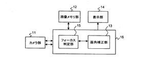
- FIG. 1 is a block diagram illustrating a configuration example of a mobile terminal according to the present embodiment.
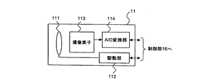
- FIG. 2 is a block diagram illustrating a configuration example of the camera unit illustrated in FIG.
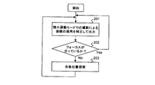
- FIG. 3 is a flowchart showing the operation of the mobile terminal of this embodiment.
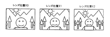
- FIG. 4A is a diagram for explaining a relationship between an image acquired in the minute motion mode and a lens position at the time of photographing.
- FIG. 4B is a diagram illustrating an example of an image acquired in the minute motion mode.
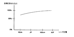
- FIG. 5 is a diagram showing an example of a graph showing the relationship between the angle of view and the lens position.
- FIG. 6 is a diagram for explaining an angle-of-view correction method for the three images shown in FIG. 4B.
- FIG. 7 is a flowchart showing the procedure of the angle of view correction method in the process of step 201 shown in FIG.
- the configuration of the mobile terminal of this embodiment will be described.
- the configuration of the portion related to the present invention will be described in detail, and the detailed description of the configuration related to the function of the mobile phone will be omitted.
- FIG. 1 is a block diagram showing a configuration example of a mobile terminal according to the present embodiment.
- FIG. 2 is a block diagram illustrating a configuration example of the camera unit illustrated in FIG.
- the portable terminal of the present embodiment includes a camera unit 11, an image memory unit 12 that stores an image output from the camera unit 11, and a display unit that outputs an image stored in the image memory unit 12. 14 and a control unit 16 that controls each unit.
- the control unit 16 includes an angle-of-view correction unit 13 that corrects an angle of view of an image captured by the camera unit 11 and a focus determination unit 15 that determines whether the image is captured from the image captured by the camera unit 11. .
- the control unit 16 is provided with a CPU (Central Processing Unit) (not shown) for executing processing according to a program and a memory (not shown) for storing the program.
- a threshold value for determining whether or not focus is achieved is described in advance.
- the camera unit 11 includes a lens 111, a driving unit 112 that moves the lens 111 in the optical axis direction, an image sensor 113 that converts an image projected through the lens 111 into an electrical signal, An A / D converter 114 that converts an electrical signal output from the image sensor 113 from an analog signal to a digital signal;
- a convex lens 111 is shown in FIG. 2, the number of lenses 111 is not limited to one, and a plurality of lenses may be provided, and the type of lens is limited to a convex type. Absent.
- the image sensor 113 is, for example, a CCD (Charge Coupled Device) or a CMOS (Complementary Metal Oxide Semiconductor) image sensor.
- the A / D conversion unit 114 converts image data received from the image sensor 113 into a digital signal and transmits the digital signal to the control unit 16.
- the image memory unit 12 may be a volatile memory such as a DRAM (Dynamic Random Access Memory) and an SRAM (Static RAM), or may be a non-volatile memory such as a flash memory.
- the image memory unit 12 stores image data captured by the camera unit 11 and image data corrected by the control unit 16.
- the display unit 14 outputs an image received from the control unit 16.
- the focus determination unit 15 of the control unit 16 causes the camera unit 11 to execute the micro motion mode at regular intervals. Specifically, the focus determination unit 15 transmits a control signal for moving the lens 111 back and forth with respect to the optical axis direction to the drive unit 112, and receives a plurality of image data received from the A / D conversion unit 114. Stored in the image memory unit 12.
- the focus determination unit 15 determines whether or not the contrast change amount exceeds the above threshold for a plurality of images based on the plurality of image data stored in the image memory unit 12. Then, the focus determination unit 15 determines that the lens 111 is not in the in-focus position when the contrast change amount exceeds the threshold value, and the lens 111 is in the in-focus position when the contrast change amount is equal to or less than the threshold value. Judge that there is.
- the focus determination unit 15 determines that the lens 111 is not in the in-focus position, the focus determination unit 15 determines, based on the contrast of the plurality of images, the position of the lens 111 where the image contrast is maximized as a new in-focus position,
- the focus position search mode is executed. Specifically, the focus determination unit 15 transmits a control signal to the drive unit 112 to move the lens 111 to the determined in-focus position.
- the part of the image where the contrast change is compared is described in advance in the program.
- a part to be compared with contrast for example, it may be a predetermined range near the center of the image, and a human face is detected by analyzing the image instantaneously, and an area including the detected face It may be.
- the “contrast” value to be compared is not the contrast value itself detected by all the pixels of the image sensor 113 shown in FIG. 2 but the adjacent pixels in the region specified as the comparison target.
- the difference between the contrast values may be obtained and the sum of the differences may be obtained. This is based on the characteristic that when the focus is on, the difference in contrast value between adjacent pixels tends to increase.
- a table indicating the relationship between the number of pulses serving as a signal for moving the lens 111 to the driving unit 112 by a predetermined distance and the moving distance of the lens 111 is stored in advance in a memory (not shown) in the control unit 16.
- the focus determination unit 15 specifies the current position of the lens 111 from the information on the number of pulses transmitted to the drive unit 112 when the drive unit 112 was last operated. Then, the focus determination unit 15 calculates a difference between the current position and the in-focus position, obtains the number of pulses corresponding to the difference from the above table, and transmits the number of pulses to the drive unit 112.
- the focus determination unit 15 receives a position signal that is a signal indicating the position of the lens 111 from the driving unit 112, and based on the position signal and the contrast of a plurality of captured images, A graph showing the change in contrast with respect to is created, and the graph is stored in a memory (not shown) in the control unit 16. Then, the focus determination unit 15 obtains a position signal when the contrast is maximized from the above graph, and transmits a control signal including the position signal and an instruction to move the lens 111 to the drive unit 112.
- the configuration of the view angle correction unit 13 shown in FIG. 1 will be described.
- the angle of view correction unit 13 has an angle of view on any one of the plurality of images based on the plurality of image data. Correct other images to match.
- the angle-of-view correction unit 13 transmits one reference image and another image after correction to the display unit 14.
- one image serving as a reference when the angle of view is corrected is referred to as a basic image.
- An example of an image correction method by the angle-of-view correction unit 13 will be described in detail later.
- the view angle correction unit 13 and the focus determination unit 15 are virtually configured in the mobile terminal by executing the program by the CPU.
- the view angle correction unit 13 and the focus determination are not described.
- Each of the units 15 or some of these functions may be configured by a dedicated integrated circuit such as a gate array.
- FIG. 3 is a flowchart showing the operation of the mobile terminal of this embodiment.
- the mobile terminal When the photographer points the camera unit 11 of the mobile terminal toward the subject and operates the mobile terminal to input a shooting preparation instruction to the mobile terminal, the mobile terminal activates the camera unit 11 and subsequently focuses on the subject. In order to determine whether or not the lens is moving, a minute motion mode is executed in which the lens 111 is photographed while moving back and forth in the optical axis direction. Then, the mobile terminal corrects the angle of view of the image obtained by shooting in the minute motion mode and outputs the corrected image to the display unit 14 (step 201).
- FIG. 4A and FIG. 4B are diagrams for explaining the relationship between the image acquired by the micro motion mode and the lens position at the time of shooting.
- 4A is a graph showing the position of the lens with respect to the optical axis direction
- FIG. 4B shows an image taken at each of the lens positions X1 to X3.
- JP in FIG. 4A indicates a focus position.
- the angle of view of the image taken at the lens position X1 is narrower than the angle of view of the image taken at the lens position X2 on the INF side relative to the in-focus position. Further, the angle of view of the image taken at the lens position X1 is wider than the angle of view of the image taken at the lens position X3 on the macro side from the in-focus position. Thus, in general, the angle of view becomes wider as the lens position is closer to the INF side or infinity ( ⁇ ) side than to the macro side.
- An example of a graph showing the relationship between the angle of view and the lens position is shown in FIG. The vertical axis of the graph shown in FIG. 5 indicates the width of the angle of view, and the horizontal axis indicates the lens position.
- FIG. 5 shows that the angle of view becomes wider as the lens position is closer to the INF side.
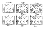
- FIG. 6 is a diagram for explaining an angle-of-view correction method for the three images shown in FIG. 4B.
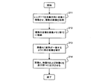
- FIG. 7 is a flowchart showing the procedure of the angle of view correction method in the process of step 201 shown in FIG.
- the mobile terminal shoots the subject while moving the lens 111 back and forth in the optical axis direction in the micro motion mode, and acquires three images with different angles of view (step 211). Subsequently, after storing the three images in the image memory unit 12 (step 212), the mobile terminal specifies an image having the narrowest angle of view among the three images as a basic image. Of the three images shown in FIG. 4B, an image (image A shown in FIG. 6) when taken at the lens position X3 is a basic image.
- the angle-of-view correction unit 13 of the mobile terminal corrects another image so that the angle of view matches the image A (step 213). Specifically, the angle-of-view correction unit 13 clips an area where the angle of view coincides with the image A from the image taken at the lens position X1, and enlarges the area to the size of the image A. Let it be image B. In FIG. 6, a range surrounded by a one-dot chain line indicates a clipping portion. Further, the field angle correction unit 13 clips an area where the field angle coincides with the image A from the image taken at the lens position X2, and expands the area to the size of the image A as an image C. To do.
- the portable terminal specifies the image with the narrowest angle of view as the basic image, and in the process of step 213, after clipping each of the images taken at the lens positions X1 and X2, the size of the image A is obtained.
- the clipped area only needs to be enlarged to the size of the image A.
- the angle-of-view correction unit 13 sequentially transmits the image A, the image B, and the image C to the display unit 14, and sequentially outputs these images to the display unit 14 (step 214).
- step 202 shown in FIG. 3 the mobile terminal determines the amount of change in contrast of the three images from the three image data stored in the image memory unit 12 in order to determine whether or not the image is in focus. It is determined whether or not exceeds a threshold value (step 202). If the contrast change amount exceeds the threshold value as a result of the determination in step 202, the mobile terminal determines that the lens 111 is not in the in-focus position. Then, the mobile terminal determines the lens position where the contrast is maximized as a new in-focus position from the relationship between the image contrast and the lens position based on the contrast of the three images, and executes the in-focus position search mode. (Step 203). After the process of step 203, the mobile terminal returns to step 201.
- step 202 determines that the lens 111 is in the in-focus position and returns to step 201.
- the mobile terminal when AF-C is executed, a plurality of images are acquired while moving the lens, and image differences corresponding to changes in the angle of view of the plurality of images are extracted so that the angles of view match.
- image differences corresponding to changes in the angle of view of the plurality of images are extracted so that the angles of view match.
- By correcting the image it is possible to suppress the change in the angle of view accompanying the minute movement of the lens. Therefore, since a configuration for individually controlling a plurality of lenses is not required, it is possible to meet a demand for downsizing a camera for a mobile device such as a mobile phone.
- the change in the angle of view of the image output to the display unit during the execution of AF-C is suppressed, there is no unpleasant feeling for the photographer who is looking at the display unit.
- the image processing method of the present embodiment can be applied not only to the change in the angle of view in the minute movement of AF-C, but also to a measure for preventing image shaking that may occur during normal AF.
- Camera shake means that the photographer's hand holding the camera trembles without being fixed, and the angle of view of the subject image taken when camera shake occurs is shifted between frames. There is a problem of end. Camera shake correction technology sets a margin of a predetermined width from the outer periphery to the inner side of all the images to be shot, and outputs by clipping the area of the same angle of view, excluding the margin, for each successive frame Or to record.
- the camera shake correction technology only clips the same area between frames and does not perform image enlargement processing. Therefore, it cannot correct the change in the angle of view caused by the movement of the lens in the optical axis direction.
- the image processing method according to the present embodiment can be said to be equivalent to a method for extracting singular points as in the difference detection technique based on the camera shake correction technique in terms of extraction of differences in image data.
- only the enlargement process or the reduction process for the change in the angle of view is performed on the difference from the basic image, and the singular points between the frames overlap, so that it is easier than the camera shake correction technique. It is.
- the present invention can be applied to a portable terminal such as a mobile phone, a PHS (Personal Handyphone System), and a PDA (Personal Digital Assistants) having a camera including an image sensor and an image processing function.
- a portable terminal such as a mobile phone, a PHS (Personal Handyphone System), and a PDA (Personal Digital Assistants) having a camera including an image sensor and an image processing function.
- the program of the present invention may be recorded on a computer-readable recording medium.
- the focus determination unit 15 is displayed in the functional block diagram illustrated in FIG. 1 in order to describe the image processing method of the present embodiment in detail.
- the portable terminal only needs to include the camera unit 11, the image memory unit 12, the angle of view correction unit 13, and the display unit 14 in the configuration illustrated in FIG.
Landscapes
- Engineering & Computer Science (AREA)
- Multimedia (AREA)
- Signal Processing (AREA)
- Physics & Mathematics (AREA)
- General Physics & Mathematics (AREA)
- Optics & Photonics (AREA)
- Studio Devices (AREA)
- Automatic Focus Adjustment (AREA)
- Focusing (AREA)
Abstract
Description
12 画像メモリ部
13 画角補正部
14 表示部
15 フォーカス判定部
16 制御部
111 レンズ
112 駆動部
113 撮像素子
Claims (10)
- レンズを光軸方向に対して前後に移動させて被写体を撮影し、画角の異なる複数の画像を出力するカメラ部と、
前記カメラ部から出力される前記複数の画像を記憶する記憶部と、
前記記憶部が記憶する前記複数の画像について、いずれか1つの画像に画角が一致するように他の画像を補正する画角補正部と、
前記1つの画像および前記画角補正部で補正された前記他の画像を出力する表示部と、
を有する携帯端末。 - 請求項1記載の携帯端末において、
前記1つの画像は、前記複数の画像のうち画角が最も狭い画像である、携帯端末。 - 請求項2記載の携帯端末において、
前記画角補正部は、
前記他の画像を補正する際、前記複数の画像のうち、前記レンズが被写体に最も近づいたときに撮影された画像を前記1つの画像に特定し、該1つの画像と画角が一致するように前記他の画像の画角を決定し、決定した画角の範囲を前記1つの画像と同等の大きさに拡大する、携帯端末。 - 請求項1から3のいずれか1項記載の携帯端末において、
前記記憶部が記憶する複数の画像のコントラストの変化量が予め決められた閾値を越えているか否かによって、前記レンズが合焦位置にあるか否かを判定するフォーカス判定部をさらに有し、
前記フォーカス判定部は、
前記複数の画像のコントラストの変化量が前記閾値を越えている場合、該複数の画像のコントラストに基づいて、画像のコントラストが最大になるレンズの位置を新たな合焦位置に決定する、携帯端末。 - レンズを含むカメラ部、記憶部、表示部、および制御部を有する携帯端末の制御部による画像処理方法であって、
前記制御部は、前記カメラ部に前記レンズを光軸方向に対して前後に移動させて被写体を撮影させ、画角の異なる複数の画像を出力させ、
前記制御部は、前記カメラ部から出力される複数の画像を前記記憶部に格納し、
前記制御部は、前記記憶部に格納された複数の画像について、いずれか1つの画像に画角が一致するように他の画像を補正し、
前記制御部は、前記1つの画像および前記画角補正部で補正された前記他の画像を前記表示部に出力させる、画像処理方法。 - 請求項5記載の画像処理方法において、
前記1つの画像は、前記複数の画像のうち画角が最も狭い画像である、画像処理方法。 - 請求項6記載の画像処理方法において、
前記制御部が前記他の画像を補正する際、
前記制御部は、前記複数の画像のうち、前記レンズが被写体に最も近づいたときに撮影された画像を前記1つの画像に特定し、
前記制御部は、前記1つの画像と画角が一致するように前記他の画像の画角を決定し、決定した画角の範囲を前記1つの画像と同等の大きさに拡大する、画像処理方法。 - 請求項5から7のいずれか1項記載の画像処理方法において、
前記制御部は、前記記憶部に格納された複数の画像のコントラストの変化量が予め決められた閾値を越えているか否かによって、前記レンズが合焦位置にあるか否かを判定し、
前記制御部は、判定の結果、前記複数の画像のコントラストの変化量が前記閾値を越えている場合、該複数の画像のコントラストに基づいて、画像のコントラストが最大になるレンズの位置を新たな合焦位置に決定する、画像処理方法。 - レンズを含むカメラ部、記憶部、表示部、および制御部を有する携帯端末の制御部に実行させるためのプログラムを記録したコンピュータ読み取り可能な記録媒体であって、
前記カメラ部に前記レンズを光軸方向に対して前後に移動させて被写体を撮影させ、画角の異なる複数の画像を出力させ、
前記カメラ部から出力される複数の画像を前記記憶部に格納し、
前記記憶部に格納された複数の画像について、いずれか1つの画像に画角が一致するように他の画像を補正し、
前記1つの画像および前記画角補正部で補正された前記他の画像を前記表示部に出力させる処理を前記制御部に実行させるためのプログラムを記録したコンピュータ読み取り可能な記録媒体。 - 請求項9記載のコンピュータ読み取り可能な記録媒体において、
前記1つの画像は、前記複数の画像のうち画角が最も狭い画像である、コンピュータ読み取り可能な記録媒体。
Priority Applications (4)
| Application Number | Priority Date | Filing Date | Title |
|---|---|---|---|
| US13/884,918 US9041853B2 (en) | 2010-12-01 | 2011-11-24 | Mobile terminal, method of image processing, and program |
| CN201180057957.4A CN103222258B (zh) | 2010-12-01 | 2011-11-24 | 移动终端、图像处理的方法 |
| JP2012546805A JPWO2012073779A1 (ja) | 2010-12-01 | 2011-11-24 | 携帯端末、画像処理方法およびプログラム |
| EP11845376.0A EP2648401B1 (en) | 2010-12-01 | 2011-11-24 | Mobile terminal, image processing method and program |
Applications Claiming Priority (2)
| Application Number | Priority Date | Filing Date | Title |
|---|---|---|---|
| JP2010268240 | 2010-12-01 | ||
| JP2010-268240 | 2010-12-01 |
Publications (1)
| Publication Number | Publication Date |
|---|---|
| WO2012073779A1 true WO2012073779A1 (ja) | 2012-06-07 |
Family
ID=46171721
Family Applications (1)
| Application Number | Title | Priority Date | Filing Date |
|---|---|---|---|
| PCT/JP2011/077018 Ceased WO2012073779A1 (ja) | 2010-12-01 | 2011-11-24 | 携帯端末、画像処理方法およびプログラム |
Country Status (5)
| Country | Link |
|---|---|
| US (1) | US9041853B2 (ja) |
| EP (1) | EP2648401B1 (ja) |
| JP (1) | JPWO2012073779A1 (ja) |
| CN (1) | CN103222258B (ja) |
| WO (1) | WO2012073779A1 (ja) |
Cited By (3)
| Publication number | Priority date | Publication date | Assignee | Title |
|---|---|---|---|---|
| JP2014204337A (ja) * | 2013-04-05 | 2014-10-27 | オリンパス株式会社 | 撮像装置、撮像装置の制御方法及びプログラム |
| US20170111588A1 (en) * | 2015-10-14 | 2017-04-20 | Qualcomm Incorporated | Constant field of view for image capture |
| US20240015393A1 (en) * | 2021-03-31 | 2024-01-11 | SZ DJI Technology Co., Ltd. | Video shooting method, device and system |
Families Citing this family (8)
| Publication number | Priority date | Publication date | Assignee | Title |
|---|---|---|---|---|
| CN104243832A (zh) * | 2014-09-30 | 2014-12-24 | 北京金山安全软件有限公司 | 通过移动终端进行拍摄的方法、装置及移动终端 |
| JP2016086249A (ja) * | 2014-10-23 | 2016-05-19 | カシオ計算機株式会社 | 表示装置、表示制御方法及び表示制御プログラム |
| JP2017062598A (ja) * | 2015-09-24 | 2017-03-30 | ソニー株式会社 | 情報処理装置、情報処理方法、およびプログラム |
| CN107155018A (zh) * | 2016-03-04 | 2017-09-12 | 阔展科技(深圳)有限公司 | 智能分析摄像机 |
| CN112312018B (zh) * | 2016-04-15 | 2022-05-17 | 深圳市大疆创新科技有限公司 | 使用自适应步长的对比度检测自动聚焦 |
| WO2018116824A1 (ja) * | 2016-12-19 | 2018-06-28 | ソニー株式会社 | 制御装置、制御方法、並びにプログラム |
| WO2018168214A1 (ja) * | 2017-03-14 | 2018-09-20 | 富士フイルム株式会社 | 撮像装置、撮像装置の信号処理方法及び撮像装置の信号処理プログラム |
| US20250260897A1 (en) * | 2022-06-03 | 2025-08-14 | Sony Group Corporation | Information processing device, information processing method, and program |
Citations (4)
| Publication number | Priority date | Publication date | Assignee | Title |
|---|---|---|---|---|
| JPH10282396A (ja) | 1997-04-04 | 1998-10-23 | Canon Inc | ズームレンズのレンズ駆動制御装置 |
| JP2008042404A (ja) * | 2006-08-03 | 2008-02-21 | Olympus Imaging Corp | デジタルカメラ |
| JP2008160622A (ja) | 2006-12-26 | 2008-07-10 | Sanyo Electric Co Ltd | 画角補正装置及び方法並びに撮像装置 |
| JP2010268240A (ja) | 2009-05-14 | 2010-11-25 | Canon Inc | 巻取り装置 |
Family Cites Families (41)
| Publication number | Priority date | Publication date | Assignee | Title |
|---|---|---|---|---|
| EP0441380B1 (en) * | 1990-02-08 | 1996-09-11 | Canon Kabushiki Kaisha | Image pick-up device |
| JP3925751B2 (ja) | 1997-06-30 | 2007-06-06 | フジノン株式会社 | 撮影レンズの画角補正装置 |
| JPH11281873A (ja) * | 1998-03-31 | 1999-10-15 | Fuji Photo Optical Co Ltd | カメラのレンズ操作装置 |
| JP4217344B2 (ja) * | 1999-06-09 | 2009-01-28 | キヤノン株式会社 | ズームレンズ、ズームレンズシステムおよびカメラシステム |
| JP3937678B2 (ja) * | 2000-03-23 | 2007-06-27 | コニカミノルタホールディングス株式会社 | 電子スチルカメラ |
| JP2001281529A (ja) * | 2000-03-29 | 2001-10-10 | Minolta Co Ltd | デジタルカメラ |
| JP3624859B2 (ja) * | 2001-06-19 | 2005-03-02 | カシオ計算機株式会社 | 撮像装置、ソフトフォーカス画像撮影方法 |
| JP4198449B2 (ja) * | 2002-02-22 | 2008-12-17 | 富士フイルム株式会社 | デジタルカメラ |
| JP3680827B2 (ja) * | 2002-08-27 | 2005-08-10 | コニカミノルタフォトイメージング株式会社 | デジタルカメラ |
| US7295232B2 (en) * | 2003-01-15 | 2007-11-13 | Canon Kabushiki Kaisha | Camera and program |
| JP2004357202A (ja) * | 2003-05-30 | 2004-12-16 | Canon Inc | 撮影装置 |
| JP4164424B2 (ja) * | 2003-08-29 | 2008-10-15 | キヤノン株式会社 | 撮像装置及び方法 |
| JP2006129211A (ja) | 2004-10-29 | 2006-05-18 | Olympus Corp | 撮像装置 |
| JP4379728B2 (ja) * | 2005-01-31 | 2009-12-09 | カシオ計算機株式会社 | 撮像装置及びそのプログラム |
| JP2006258944A (ja) * | 2005-03-15 | 2006-09-28 | Fujinon Corp | オートフォーカスシステム |
| JP5013705B2 (ja) * | 2005-11-21 | 2012-08-29 | 三星電子株式会社 | 撮像装置,画面表示方法,焦点調整方法,露出調整方法,およびコンピュータプログラム |
| JP2007199195A (ja) | 2006-01-24 | 2007-08-09 | Fujinon Corp | レンズ制御装置 |
| JP4333685B2 (ja) * | 2006-03-29 | 2009-09-16 | セイコーエプソン株式会社 | カメラ、画像表示方法及びそのプログラム |
| JP4262263B2 (ja) * | 2006-06-07 | 2009-05-13 | キヤノン株式会社 | 撮像装置及びその制御方法 |
| TWI309329B (en) * | 2006-10-03 | 2009-05-01 | Novatek Microelectronics Corp | Focus system and method for camera |
| JP5016909B2 (ja) * | 2006-12-15 | 2012-09-05 | キヤノン株式会社 | 撮像装置 |
| US7639935B2 (en) * | 2007-03-28 | 2009-12-29 | Sony Ericsson Mobile Communications Ab | Zoom control |
| JP4582423B2 (ja) * | 2007-04-20 | 2010-11-17 | 富士フイルム株式会社 | 撮像装置、画像処理装置、撮像方法、及び画像処理方法 |
| US20090009651A1 (en) * | 2007-07-04 | 2009-01-08 | Sanyo Electric Co., Ltd. | Imaging Apparatus And Automatic Focus Control Method |
| JP4544282B2 (ja) * | 2007-09-14 | 2010-09-15 | ソニー株式会社 | データ処理装置、およびデータ処理方法、並びにプログラム |
| JP4974912B2 (ja) * | 2008-01-22 | 2012-07-11 | キヤノン株式会社 | 撮像装置 |
| JP4843002B2 (ja) * | 2008-01-25 | 2011-12-21 | ソニー株式会社 | 撮像装置、および撮像装置制御方法、並びにコンピュータ・プログラム |
| US8300136B2 (en) * | 2008-06-26 | 2012-10-30 | Canon Kabushiki Kaisha | Imaging apparatus for detecting a face image and imaging method |
| JP5223644B2 (ja) * | 2008-12-15 | 2013-06-26 | パナソニック株式会社 | 撮像装置 |
| JP2010147715A (ja) * | 2008-12-17 | 2010-07-01 | Hoya Corp | 撮像装置 |
| JP4780205B2 (ja) | 2009-02-23 | 2011-09-28 | カシオ計算機株式会社 | 撮像装置、画角調節方法、及び、プログラム |
| JP5206494B2 (ja) * | 2009-02-27 | 2013-06-12 | 株式会社リコー | 撮像装置、画像表示装置と、撮像方法及び画像表示方法並びに合焦領域枠の位置補正方法 |
| JP5299912B2 (ja) * | 2009-04-20 | 2013-09-25 | 株式会社ザクティ | 撮像装置及び画像ファイルのデータ構造 |
| JP4784678B2 (ja) * | 2009-04-22 | 2011-10-05 | カシオ計算機株式会社 | 撮像装置、撮像方法及びプログラム |
| US8743269B2 (en) * | 2009-06-15 | 2014-06-03 | Olympus Imaging Corp. | Photographing device, photographing method, and playback method |
| JP5120356B2 (ja) * | 2009-10-13 | 2013-01-16 | 株式会社ニコン | 撮像装置 |
| JP2011135490A (ja) * | 2009-12-25 | 2011-07-07 | Seiko Epson Corp | デジタルカメラおよびその製造方法 |
| JP2011210139A (ja) * | 2010-03-30 | 2011-10-20 | Sony Corp | 画像処理装置および方法、並びにプログラム |
| JP5810505B2 (ja) * | 2010-11-01 | 2015-11-11 | 株式会社ソシオネクスト | 撮像制御装置、撮像装置、及び撮像制御方法 |
| US8526805B2 (en) * | 2010-12-20 | 2013-09-03 | Canon Kabushiki Kaisha | Lens apparatus and camera system including the same |
| EP2574065B1 (en) * | 2011-01-26 | 2016-09-07 | FUJIFILM Corporation | Image processing device, image-capturing device, reproduction device, and image processing method |
-
2011
- 2011-11-24 WO PCT/JP2011/077018 patent/WO2012073779A1/ja not_active Ceased
- 2011-11-24 JP JP2012546805A patent/JPWO2012073779A1/ja active Pending
- 2011-11-24 US US13/884,918 patent/US9041853B2/en not_active Expired - Fee Related
- 2011-11-24 CN CN201180057957.4A patent/CN103222258B/zh not_active Expired - Fee Related
- 2011-11-24 EP EP11845376.0A patent/EP2648401B1/en not_active Not-in-force
Patent Citations (4)
| Publication number | Priority date | Publication date | Assignee | Title |
|---|---|---|---|---|
| JPH10282396A (ja) | 1997-04-04 | 1998-10-23 | Canon Inc | ズームレンズのレンズ駆動制御装置 |
| JP2008042404A (ja) * | 2006-08-03 | 2008-02-21 | Olympus Imaging Corp | デジタルカメラ |
| JP2008160622A (ja) | 2006-12-26 | 2008-07-10 | Sanyo Electric Co Ltd | 画角補正装置及び方法並びに撮像装置 |
| JP2010268240A (ja) | 2009-05-14 | 2010-11-25 | Canon Inc | 巻取り装置 |
Non-Patent Citations (1)
| Title |
|---|
| See also references of EP2648401A4 |
Cited By (4)
| Publication number | Priority date | Publication date | Assignee | Title |
|---|---|---|---|---|
| JP2014204337A (ja) * | 2013-04-05 | 2014-10-27 | オリンパス株式会社 | 撮像装置、撮像装置の制御方法及びプログラム |
| US20170111588A1 (en) * | 2015-10-14 | 2017-04-20 | Qualcomm Incorporated | Constant field of view for image capture |
| US9992423B2 (en) * | 2015-10-14 | 2018-06-05 | Qualcomm Incorporated | Constant field of view for image capture |
| US20240015393A1 (en) * | 2021-03-31 | 2024-01-11 | SZ DJI Technology Co., Ltd. | Video shooting method, device and system |
Also Published As
| Publication number | Publication date |
|---|---|
| CN103222258A (zh) | 2013-07-24 |
| JPWO2012073779A1 (ja) | 2014-05-19 |
| EP2648401A4 (en) | 2014-04-23 |
| EP2648401B1 (en) | 2015-08-26 |
| US9041853B2 (en) | 2015-05-26 |
| US20130229547A1 (en) | 2013-09-05 |
| CN103222258B (zh) | 2016-06-08 |
| EP2648401A1 (en) | 2013-10-09 |
Similar Documents
| Publication | Publication Date | Title |
|---|---|---|
| WO2012073779A1 (ja) | 携帯端末、画像処理方法およびプログラム | |
| JP5764740B2 (ja) | 撮像装置 | |
| CN105391918B (zh) | 图像处理装置及控制图像处理装置的方法 | |
| JP6594524B2 (ja) | 撮像装置、作動方法、画像処理装置及び画像処理方法 | |
| JPWO2008010559A1 (ja) | 撮像装置 | |
| JP2015216485A (ja) | 撮像装置、撮像装置の制御方法、プログラム、および、記憶媒体 | |
| JP2008078945A (ja) | 手ぶれ補正機能付き撮像装置、手ぶれ補正方法、および、手ぶれ補正処理プログラム | |
| JP6188474B2 (ja) | ズーム制御装置、ズーム制御装置の制御方法、ズーム制御装置の制御プログラムおよび記憶媒体 | |
| JP5696419B2 (ja) | 画像処理装置及び方法、並びにプログラム | |
| US9274402B2 (en) | Imaging device that executes auto focus control by referring to distance image data regarding a depth of a region | |
| JP2008301355A (ja) | 撮像装置及びそのプログラム | |
| JP5393877B2 (ja) | 撮像装置および集積回路 | |
| JP5436116B2 (ja) | 画像処理装置、撮像装置、及び制御方法 | |
| JP6245923B2 (ja) | 撮像装置、撮像装置の制御方法、撮像装置の制御プログラムおよび記憶媒体 | |
| JP6172973B2 (ja) | 画像処理装置 | |
| JP7672809B2 (ja) | 撮像装置、撮像方法、プログラムおよび記録媒体 | |
| JP5760654B2 (ja) | 画像処理装置、画像処理方法及びプログラム | |
| JP2020188452A (ja) | 撮像装置およびその制御方法 | |
| JP2015233211A (ja) | 撮像装置およびその制御方法ならびにプログラム | |
| JP5182395B2 (ja) | 撮像装置、撮像方法および撮像プログラム | |
| US20250310640A1 (en) | Image processing apparatus and method, electronic apparatus, and storage medium | |
| JP6234103B2 (ja) | ズーム制御装置、ズーム制御装置の制御方法、ズーム制御装置の制御プログラムおよび記憶媒体 | |
| US12444031B2 (en) | Image processing apparatus, imaging apparatus, image processing method, and recording medium background | |
| JP5603671B2 (ja) | 電子機器、撮像方法、及び画像変換プログラム | |
| JP2015026906A (ja) | 撮像装置、撮像装置の制御方法、撮像装置の制御プログラムおよび記憶媒体 |
Legal Events
| Date | Code | Title | Description |
|---|---|---|---|
| 121 | Ep: the epo has been informed by wipo that ep was designated in this application |
Ref document number: 11845376 Country of ref document: EP Kind code of ref document: A1 |
|
| WWE | Wipo information: entry into national phase |
Ref document number: 13884918 Country of ref document: US Ref document number: 2011845376 Country of ref document: EP |
|
| ENP | Entry into the national phase |
Ref document number: 2012546805 Country of ref document: JP Kind code of ref document: A |
|
| NENP | Non-entry into the national phase |
Ref country code: DE |