WO2012077656A1 - ZnO化合物被覆硫黄含有蛍光体 - Google Patents
ZnO化合物被覆硫黄含有蛍光体 Download PDFInfo
- Publication number
- WO2012077656A1 WO2012077656A1 PCT/JP2011/078127 JP2011078127W WO2012077656A1 WO 2012077656 A1 WO2012077656 A1 WO 2012077656A1 JP 2011078127 W JP2011078127 W JP 2011078127W WO 2012077656 A1 WO2012077656 A1 WO 2012077656A1
- Authority
- WO
- WIPO (PCT)
- Prior art keywords
- phosphor
- zno
- sulfur
- zno compound
- coated
- Prior art date
- Legal status (The legal status is an assumption and is not a legal conclusion. Google has not performed a legal analysis and makes no representation as to the accuracy of the status listed.)
- Ceased
Links
Images






Classifications
-
- C—CHEMISTRY; METALLURGY
- C09—DYES; PAINTS; POLISHES; NATURAL RESINS; ADHESIVES; COMPOSITIONS NOT OTHERWISE PROVIDED FOR; APPLICATIONS OF MATERIALS NOT OTHERWISE PROVIDED FOR
- C09K—MATERIALS FOR MISCELLANEOUS APPLICATIONS, NOT PROVIDED FOR ELSEWHERE
- C09K11/00—Luminescent materials, e.g. electroluminescent or chemiluminescent
- C09K11/08—Luminescent materials, e.g. electroluminescent or chemiluminescent containing inorganic luminescent materials
-
- H—ELECTRICITY
- H10—SEMICONDUCTOR DEVICES; ELECTRIC SOLID-STATE DEVICES NOT OTHERWISE PROVIDED FOR
- H10H—INORGANIC LIGHT-EMITTING SEMICONDUCTOR DEVICES HAVING POTENTIAL BARRIERS
- H10H20/00—Individual inorganic light-emitting semiconductor devices having potential barriers, e.g. light-emitting diodes [LED]
- H10H20/80—Constructional details
- H10H20/85—Packages
- H10H20/851—Wavelength conversion means
- H10H20/8511—Wavelength conversion means characterised by their material, e.g. binder
- H10H20/8512—Wavelength conversion materials
- H10H20/8513—Wavelength conversion materials having two or more wavelength conversion materials
-
- C—CHEMISTRY; METALLURGY
- C09—DYES; PAINTS; POLISHES; NATURAL RESINS; ADHESIVES; COMPOSITIONS NOT OTHERWISE PROVIDED FOR; APPLICATIONS OF MATERIALS NOT OTHERWISE PROVIDED FOR
- C09K—MATERIALS FOR MISCELLANEOUS APPLICATIONS, NOT PROVIDED FOR ELSEWHERE
- C09K11/00—Luminescent materials, e.g. electroluminescent or chemiluminescent
- C09K11/02—Use of particular materials as binders, particle coatings or suspension media therefor
- C09K11/025—Use of particular materials as binders, particle coatings or suspension media therefor non-luminescent particle coatings or suspension media
-
- C—CHEMISTRY; METALLURGY
- C09—DYES; PAINTS; POLISHES; NATURAL RESINS; ADHESIVES; COMPOSITIONS NOT OTHERWISE PROVIDED FOR; APPLICATIONS OF MATERIALS NOT OTHERWISE PROVIDED FOR
- C09K—MATERIALS FOR MISCELLANEOUS APPLICATIONS, NOT PROVIDED FOR ELSEWHERE
- C09K11/00—Luminescent materials, e.g. electroluminescent or chemiluminescent
- C09K11/08—Luminescent materials, e.g. electroluminescent or chemiluminescent containing inorganic luminescent materials
- C09K11/56—Luminescent materials, e.g. electroluminescent or chemiluminescent containing inorganic luminescent materials containing sulfur
-
- C—CHEMISTRY; METALLURGY
- C09—DYES; PAINTS; POLISHES; NATURAL RESINS; ADHESIVES; COMPOSITIONS NOT OTHERWISE PROVIDED FOR; APPLICATIONS OF MATERIALS NOT OTHERWISE PROVIDED FOR
- C09K—MATERIALS FOR MISCELLANEOUS APPLICATIONS, NOT PROVIDED FOR ELSEWHERE
- C09K11/00—Luminescent materials, e.g. electroluminescent or chemiluminescent
- C09K11/08—Luminescent materials, e.g. electroluminescent or chemiluminescent containing inorganic luminescent materials
- C09K11/62—Luminescent materials, e.g. electroluminescent or chemiluminescent containing inorganic luminescent materials containing gallium, indium or thallium
-
- C—CHEMISTRY; METALLURGY
- C09—DYES; PAINTS; POLISHES; NATURAL RESINS; ADHESIVES; COMPOSITIONS NOT OTHERWISE PROVIDED FOR; APPLICATIONS OF MATERIALS NOT OTHERWISE PROVIDED FOR
- C09K—MATERIALS FOR MISCELLANEOUS APPLICATIONS, NOT PROVIDED FOR ELSEWHERE
- C09K11/00—Luminescent materials, e.g. electroluminescent or chemiluminescent
- C09K11/08—Luminescent materials, e.g. electroluminescent or chemiluminescent containing inorganic luminescent materials
- C09K11/77—Luminescent materials, e.g. electroluminescent or chemiluminescent containing inorganic luminescent materials containing rare earth metals
- C09K11/7728—Luminescent materials, e.g. electroluminescent or chemiluminescent containing inorganic luminescent materials containing rare earth metals containing europium
- C09K11/7729—Chalcogenides
- C09K11/7731—Chalcogenides with alkaline earth metals
-
- H—ELECTRICITY
- H10—SEMICONDUCTOR DEVICES; ELECTRIC SOLID-STATE DEVICES NOT OTHERWISE PROVIDED FOR
- H10H—INORGANIC LIGHT-EMITTING SEMICONDUCTOR DEVICES HAVING POTENTIAL BARRIERS
- H10H20/00—Individual inorganic light-emitting semiconductor devices having potential barriers, e.g. light-emitting diodes [LED]
- H10H20/80—Constructional details
- H10H20/85—Packages
- H10H20/851—Wavelength conversion means
-
- H—ELECTRICITY
- H10—SEMICONDUCTOR DEVICES; ELECTRIC SOLID-STATE DEVICES NOT OTHERWISE PROVIDED FOR
- H10H—INORGANIC LIGHT-EMITTING SEMICONDUCTOR DEVICES HAVING POTENTIAL BARRIERS
- H10H20/00—Individual inorganic light-emitting semiconductor devices having potential barriers, e.g. light-emitting diodes [LED]
- H10H20/80—Constructional details
- H10H20/85—Packages
- H10H20/852—Encapsulations
-
- Y—GENERAL TAGGING OF NEW TECHNOLOGICAL DEVELOPMENTS; GENERAL TAGGING OF CROSS-SECTIONAL TECHNOLOGIES SPANNING OVER SEVERAL SECTIONS OF THE IPC; TECHNICAL SUBJECTS COVERED BY FORMER USPC CROSS-REFERENCE ART COLLECTIONS [XRACs] AND DIGESTS
- Y10—TECHNICAL SUBJECTS COVERED BY FORMER USPC
- Y10T—TECHNICAL SUBJECTS COVERED BY FORMER US CLASSIFICATION
- Y10T428/00—Stock material or miscellaneous articles
- Y10T428/25—Web or sheet containing structurally defined element or component and including a second component containing structurally defined particles
- Y10T428/256—Heavy metal or aluminum or compound thereof
Definitions
- the present invention relates to a sulfur-containing phosphor containing sulfur in the matrix.
- red phosphors include sulfur-containing phosphors containing sulfur in the base material, such as (Ca, Sr) S: Eu, (Zn, Cd) (S, Se): Ag, Ba 2 ZnS 3 : Mn.
- Patent Document 1 and Patent Document 2 include calcium sulfide (CaS) as a base material, Eu as a luminescent center (activator), Mn, Li, Cl, Ce, Gd and the like as sensitizers ( A red phosphor contained as a coactivator) is disclosed.
- sulfide-based thiogallate phosphors represented by (Ca, Sr, Ba) (Al, Ga, In) 2 S 4 : Eu are known as green phosphors (Patent Documents 3 and 4).
- sulfur-containing phosphors such as SrS: Ce, (Sr, Ca) Ga 2 S 4 : Ce, BaAl 2 S 4 : Eu, Ba 2 SiS 4 : Ce are known as blue phosphors. It has been.
- the sulfur containing fluorescent substance which contains sulfur in a base material is excited by LED etc. and can light-emit various colors with a composition
- development is progressing as various fluorescent substance.
- this type of sulfur-containing phosphor easily reacts with water, when it is stored or used in the atmosphere, it reacts with moisture in the atmosphere and hydrolyzes to degrade the phosphor and emit light. I had the problem of getting weak.
- hydrogen sulfide gas is generated by the reaction of sulfur and water in the sulfur-containing phosphor, and when this hydrogen sulfide gas is used in a white LED element, the silicone resin mixed with the phosphor is cured.
- Ag reflection film an Ag plating film
- Patent Document 6 Patent Document 7, Patent Document 8, Patent Document 9, Patent Document 10
- Patent Document 11 A method of coating the surface of particles by a chemical vapor reaction method
- Patent Document 12 A method of attaching metal compound particles
- the phosphor When the phosphor is coated with glass, the water resistance is increased, so that the disadvantage that the phosphor deteriorates due to moisture in the atmosphere and the light emission becomes weak is solved. However, it is difficult to suppress the adverse effect of hydrogen sulfide gas, and for example, the effect of preventing corrosion of the Ag reflecting film has not been recognized.
- the present invention proposes a new coated phosphor that can effectively suppress the adverse effects of hydrogen sulfide gas.
- the present invention proposes a ZnO compound-coated sulfur-containing phosphor having a structure in which a ZnO compound containing Zn and O is present on the surface side of a sulfur-containing phosphor containing sulfur as a base material.
- the ZnO compound has a characteristic of chemically adsorbing sulfur, if the ZnO compound is present on the surface side of the sulfur-containing phosphor, even if hydrogen sulfide gas is generated, the ZnO compound absorbs it. The adverse effect of hydrogen sulfide gas can be effectively suppressed. Moreover, since the ZnO compound does not absorb light such as LED and does not affect the color, the ZnO compound is excellent in that it does not deteriorate the fluorescence characteristics of the phosphor itself.
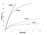
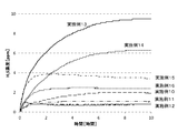
- FIG. 5 is a graph showing the evaluation test results of the hydrogen sulfide gas generation amount for Example 1-3, in which the horizontal axis represents the elapsed time (hours) stored in the thermostat, and the vertical axis represents the hydrogen sulfide concentration (ppm). Yes.
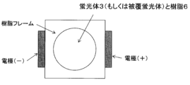
- FIG. 11 is a top view of LED packages (before phosphor filling) produced in Examples 24 to 43 and Comparative Examples 10 to 17.
- FIG. 11 is a partially enlarged top view of the LED package (after phosphor filling) shown in FIG. 10.
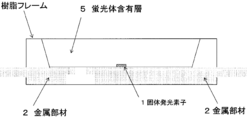
- FIG. 14 is a longitudinal sectional view of LED packages manufactured in Examples 24 to 43 and Comparative Examples 10 to 17.
- the phosphor according to the present embodiment (hereinafter referred to as “the present phosphor”) has a configuration in which a ZnO compound containing Zn and O is present on the surface side of a sulfur-containing phosphor containing sulfur in the crystal matrix. And a powder (hereinafter referred to as “the present phosphor powder”) made of ZnO compound-coated sulfur-containing phosphor particles (hereinafter referred to as “the present phosphor particles”).
- the presence of the ZnO compound on the surface side of the sulfur-containing phosphor means that the surface of the sulfur-containing phosphor is in contact with the surface of the sulfur-containing phosphor and the ZnO compound. It is meant to include the case where an arbitrary substance or layer is interposed therebetween.
- the specific composition is not particularly limited. Whatever the composition, if the matrix contains sulfur (S), it may react with moisture in the air to generate hydrogen sulfide gas, and the ZnO compound is formed on the phosphor surface side. This is because it can be considered that the generated hydrogen sulfide gas can be absorbed regardless of the composition of the phosphor.
- crystal matrix of the phosphor examples include, for example, (Ca, Sr, Ba) S, (Zn, Cd) (S, Se), Ba 2 ZnS 3 , (Ca, Sr, Ba) (Al, Ga, In) 2 S 4 : Eu, (Ca, Sr, Ba) Ga 2 S 4 , BaAl 2 S 4 , Ba 2 SiS 4 and the like. However, it is not limited to these.
- an activating element or a co-activating element luminescent center (luminescent ion) combined with such a crystal matrix for example, Sc, Ce, Pr, Nd, Pm, Sm, Eu, Tb, Dy, Ho, Er, Tm And ions of rare earth metals such as Yb and transition metals such as Cr, Ti, Ag, Cu, Au, Al, Mn, and Sb.
- luminescent center for example, Sc, Ce, Pr, Nd, Pm, Sm, Eu, Tb, Dy, Ho, Er, Tm And ions of rare earth metals such as Yb and transition metals such as Cr, Ti, Ag, Cu, Au, Al, Mn, and Sb.
- this phosphor examples include, for example, Ba 2 (Si 1-x Al x ) S 4 : Ce (where x is 0 ⁇ x ⁇ 1), SrS: Ce, green fluorescence as a blue phosphor.
- the phosphor is optionally added with various additives such as plasticizers, pigments, antioxidants, heat stabilizers, UV absorbers, light stabilizers, flame retardants, lubricants, foaming agents, fillers, antistatic agents, You may contain suitably reinforcing agents, such as a fiber.
- the particle shape of the phosphor particles is not particularly limited.
- the particle size of the phosphor powder is not particularly limited, but from the viewpoint of dispersibility, the D50 based on the volume-based particle size distribution obtained by measurement by the laser diffraction / scattering particle size distribution measurement method is 0.1 ⁇ m to 50 ⁇ m. Preferably, it is 1 ⁇ m or more or 30 ⁇ m or less, and more preferably 2 ⁇ m or more or 20 ⁇ m or less. If D50 is 0.1 ⁇ m or more, the luminous efficiency does not tend to decrease, and the phosphor particles do not aggregate. Moreover, if it is 50 micrometers or less, dispersibility can be maintained and application
- ZnO compound A ZnO compound containing Zn and O has the characteristics that it reacts with hydrogen sulfide gas and does not absorb light such as LED and does not affect the color, in other words, it is white and transparent. Yes. Therefore, the specific composition of the ZnO compound is not limited.
- a ZnO compound containing Zn and O includes ZnO, Zn (OH) 2 , ZnSO 4 .nH 2 O (0 ⁇ n ⁇ 7), ZnTi 2 O 4 , Zn 2 Ti 3 O 8 , Zn 2 TiO 4 ZnTiO.
- One or two or more kinds of crystalline fine particles selected from the group consisting of 6 to 10 , ZnSnO 3 , and Zn 2 SnO 4 may be mentioned, and those having other compositions may also be used.
- an organic acid zinc salt such as zinc stearate may be used.
- the ZnO compound exists as ZnO compound fine particles on the surface side of the sulfur-containing phosphor, the influence of hydrogen sulfide gas can be reduced. It has been confirmed that it is not necessary to coat the surface side of the sulfur-containing phosphor as a ZnO compound layer formed by continuously connecting the layers. Furthermore, if it exists as ZnO compound particles, the surface area for adsorbing hydrogen sulfide is increased and the adsorption capability of hydrogen sulfide is superior compared to the case where a film made of ZnO compound is formed.
- the present phosphor includes those in which there is a portion where the ZnO compound is not attached to the surface side of the sulfur-containing phosphor, while the film made of the ZnO compound covers the surface side of the sulfur-containing phosphor. Does not include the state.
- the ZnO compound layer in which ZnO compound particles are continuously connected may be disposed on the surface side of the sulfur-containing phosphor, which is a preferable mode.
- the ZnO compound and the sulfur of the phosphor are not chemically bonded. This is because when the phosphor S and Zn of the ZnO compound react to form ZnS through chemical bonding, the reaction with the hydrogen sulfide gas is not only inhibited, but also causes a new corrosion factor of the Ag reflecting film. Therefore, the ZnO compound only needs to be physically attached to the surface side of the sulfur-containing phosphor.
- Example 4 when Example 4 (without glass substrate) described later and Example 11 (with B2O3-SiO2 glass substrate) are compared, Example 4 has a larger amount of zinc (NZn / NS). In Example 11, the generation of hydrogen sulfide is less (Ag reflectivity can be maintained high), so that the direct reaction between ZnO and phosphor S does not cause excellent reactivity with hydrogen sulfide gas. It has been confirmed that.
- the ZnO compound is preferably a fine particle having an average particle diameter of 0.3 ⁇ m or less by SEM or TEM observation, and more preferably the average particle diameter is 1 nm or more or 100 nm or less.
- An average particle size of 0.3 ⁇ m or less is preferable because the ZnO compound particles do not scatter the light emitted from the LED and do not prevent the phosphor from absorbing the light emitted from the LED. Further, since the purpose of coating the ZnO compound is to adsorb hydrogen sulfide gas, it is preferable that the specific surface area of the ZnO compound is large from this point as well.
- the average particle diameter by SEM or TEM observation is an arbitrary 100 average particle diameters observed in arbitrary 10 fields of view, and when the particles have an aspect ratio, the average value of the long diameter and the short diameter is It is set as the particle size of the particle.
- the ratio of atomic number N Zn of Zn in the ZnO compound N it is preferably Zn / N S is 0.0050 or more, particularly 0.0100 or more, and more preferably among others 0.0200 or more.
- the ratio of atomic number N Zn of Zn in the ZnO compound N Zn / N S is preferably 1.000 or less, more preferably 0.5000 or less, and even more preferably 0.3000 or less.
- the ZnO compound powder is added to a solvent (for example, ethanol) and ultrasonically dispersed, and after adding the sulfur-containing phosphor powder and stirring,
- the ZnO compound may be attached to the surface of the sulfur-containing phosphor particles by evaporation. Further, even if the sulfur-containing phosphor powder and the ZnO compound powder are dry-mixed using a blender or the like, it is possible to make the sulfur-containing phosphor particles adhere to the surface of the sulfur-containing phosphor particles.
- examples of the production method for forming the ZnO compound layer on the surface side of the sulfur-containing phosphor include a chemical vapor reaction method.
- the phosphor particles further include a glass layer containing a glass composition, the water resistance can be increased.
- the present phosphor particles are provided with a glass layer
- a ZnO compound is present on the surface of the sulfur-containing phosphor
- a glass layer may be provided so as to cover this, or the surface of the sulfur-containing phosphor.
- a glass layer may be formed, and a ZnO compound layer may be formed on the surface of the glass layer.
- the glass layer only needs to contain a glass composition.
- the glass composition include SiO 2 , B 2 O 3 —SiO 2 , Ma 2 O—MbO—B 2 O 3 —SiO 2 , (Ma Can be exemplified by glass having a composition such as alkali metal and Mb is alkaline earth metal or Zn), but is not limited thereto.
- a precursor mixture containing the precursor of the glass layer, water, and a solvent is prepared, the precursor mixture and phosphor particles are mixed, and a sol-gel reaction is induced to induce fluorescence.
- the phosphor particles may be dried and heat-treated.
- the phosphor particles and the glass composition powder are mixed and the glass composition powder and the phosphor particles are heat treated so that the glass composition powder is melted and surrounds the phosphor particles, The mixture may be cooled.
- a method of coating the surface of the phosphor particles by a chemical vapor reaction method, a method of attaching metal compound particles, or the like may be employed.
- the glass layer is dense and continuous in order to maintain the light emission of the phosphor. However, if the glass layer is dense and continuous, the glass layer is not attached to a part of the surface of the phosphor. There may be a portion where the phosphor surface is exposed. Moreover, although the glass composition containing Zn was mentioned as an example of a glass composition, since it is preferable that a glass layer is dense and continuous, the surface area of a glass layer is small, and the adsorption capability of the hydrogen sulfide gas of a glass layer Is insufficient to prevent corrosion of the Ag reflecting film.
- spinel fine particles fine particles having a spinel crystal structure and having a particle size of less than 0.1 ⁇ m
- spinel fine particles are preferably disposed around the ZnO compound or the ZnO compound layer, preferably the ZnO compound or the It may be present in contact with the ZnO compound layer.
- chemical stability is high, and therefore many compounds are stable to high temperatures and water, and depending on the composition, they are colorless and transparent.
- the particle diameter is less than 0.1 ⁇ m, even if the phosphor is present in the vicinity of the phosphor, the phosphor absorbs light of a certain wavelength and does not hinder the emission of light of a different wavelength. Therefore, if the spinel fine particles are present around the ZnO compound or the ZnO compound layer, it is possible to further suppress the ZnO compound from absorbing moisture and whitening.
- spinel fine particles In order to allow spinel fine particles to be present around the ZnO compound or the ZnO compound layer, it may be performed in the same manner as in the production method in which a ZnO compound is present as described above. However, in order for spinel particles to exist around the ZnO compound, the ZnO compound and the spinel particles are mixed and adhered to the surface side of the sulfur-containing phosphor, or the ZnO compound is adhered to the surface side of the sulfur-containing phosphor. And spinel fine particles may be deposited thereon. However, it is not limited to these methods.
- the amount of the spinel fine particles is not particularly limited, and is, for example, 5 to 95% by mass of the ZnO compound, especially 10% by mass or more and 70% by mass or less, and more preferably 25% by mass or more or 50% by mass or less. Is preferred.
- the spinel fine particles include composite oxide fine particles having a spinel crystal structure such as ZnAl 2 O 4 , ZnGa 2 O 4 , and Zn 2 TiO 4 .
- the particle size of the spinel fine particles is preferably less than 0.1 ⁇ m from the viewpoint of ensuring transparency, particularly 0.07 ⁇ m or less, and more preferably 0.05 ⁇ m or less. Is particularly preferred.
- the layer containing the spinel fine particles is provided so as to be in contact with the ZnO compound or the ZnO compound layer, the same effect as the case where the spinel fine particles are present around the ZnO compound or the ZnO compound is provided. Can be considered.
- the phosphor particles are one kind of hydroxide, oxide or fluoride selected from the group consisting of Ti, Mg, Ca, Sr, Ba, Al, Ga, In, Sn, Zr and Y, or two or more kinds thereof.
- a water-resistant layer containing a mixture of these may be further provided.
- One kind of hydroxide, oxide or fluoride selected from the group consisting of Ti, Mg, Ca, Sr, Ba, Al, Ga, In, Sn, Zr and Y is particularly excellent in water resistance.
- the water resistant layer may be present inside or outside the ZnO compound or the ZnO compound. Moreover, when coexisting with the said glass layer, you may exist in the inner side or the outer side of this glass layer. Furthermore, the water resistant material may be included in the glass layer.
- the amount of the water resistant material is not particularly limited. For example, it is preferably 0.1 to 50% by mass, more preferably 1% by mass or more and 30% by mass or less, and particularly preferably 3% by mass or more and 15% by mass or less, based on the sulfur-containing phosphor.
- the method for forming the water-resistant layer is not particularly limited, and may be performed in the same manner as the production method in which a ZnO compound is present as described above.
- a method capable of forming a denser layer a method such as a chemical vapor reaction method can be given as a preferred example.
- the phosphor can be used in various applications by constituting a light emitting element or device by being disposed in the vicinity of a light emitting source such as an LED, a laser, or a diode. For example, it may be disposed on the LED directly or indirectly through an adhesive or adhesive.
- a light emitting source such as an LED, a laser, or a diode.
- it may be disposed on the LED directly or indirectly through an adhesive or adhesive.
- a backlight of an image display device such as a liquid crystal display device in addition to a lighting device and a special light source.
- an electric field source or an electron source in the vicinity of the light emitter and arranging it in the vicinity thereof, it can be used for display devices such as EL, FED, and CRT.
- the vicinity of the light emitter refers to a position where the light emitted by the light emitter can be received. More specifically, for example, it includes at least one LED chip and at least one phosphor, and the phosphor absorbs at least part of the light emitted from the LED, and the light emitted from the LED and the fluorescence.
- a wavelength-converting light-emitting element that obtains light in which light emitted from the body is mixed can be formed, and can be used as a light-emitting element of a lighting device or an image display device.
- a light emitting device having a structure in which a solid light emitting element such as an LED is disposed on a metal member as a reflection plate and a phosphor containing layer formed by blending the phosphor with a resin is formed.
- the device can be configured.
- a part of the ZnO compound of the phosphor is separated from the yellow-containing phosphor and scattered in the resin.
- the detached ZnO compound may be dispersed uniformly or non-uniformly in the phosphor-containing layer, or may be scattered with a concentration distribution in the depth direction. Moreover, it may settle and be scattered in layers.
- the metal member in the light emitting device examples include a metal member that reacts with a sulfur-based gas, such as a metal or an alloy containing at least one group VIII-based metal or group IB-based metal. Specific examples include silver, silver-based alloys, copper, copper-based alloys, nickel, nickel-based alloys, iron, and iron-based alloys.
- a transparent or white thermoplastic resin, a transparent or white thermosetting resin, and a transparent or white photocurable resin can be used as the resin in the light emitting device.
- the light-emitting device can be suitably used as a part of a visual device such as a lighting device such as an LED bulb device or an LED lighting device, a backlight of a liquid crystal television, a traffic light or an indicator.
- a visual device such as a lighting device such as an LED bulb device or an LED lighting device, a backlight of a liquid crystal television, a traffic light or an indicator.
- the top of the sieve having a mesh size of 440 mesh was collected under the sieve to obtain a phosphor powder (sample) made of SrGa 2 S 4 : Eu 2+ .
- a phosphor powder (sample) made of SrGa 2 S 4 : Eu 2+ .
- the sieve top having a mesh size of 440 mesh was collected under the sieve to obtain a phosphor powder (sample) made of CaS: Eu 2+ .
- a phosphor powder made of CaS: Eu 2+ .
- Comparative Example 3 Synthesis of B 2 O 3 —SiO 2 Glass-Coated SrGa 2 S 4 : Eu 2+ Phosphor Pure water, Si (OEt) 4 , H 3 BO 3 were added to ethanol in which the SrGa 2 S 4 : Eu 2+ phosphor suspended in Comparative Example 1 was suspended, and a small amount of aqueous ammonia was added as a catalyst. Hydrolysis was performed at 60 ° C. to synthesize a glass precursor / phosphor complex in which a phosphor precursor surface was coated with a glass precursor gel. This complex was heat treated at 600 ° C.
- B 2 O 3 -SiO 2 glass was coated B 2 O 3 -SiO 2 glass-coated SrGa 2 S 4: obtain a Eu 2+ phosphor.
- Zn was not detected.
- the mass ratio of the phosphor component and the glass component (SiO 2 and B 2 O 3 ) was 1: 0.0383.
- Comparative Example 4 Synthesis of SiO 2 Glass-Coated CaS: Eu 2+ Phosphor Pure water and Si (OEt) 4 are added to ethanol in which the CaS: Eu 2+ phosphor obtained in Comparative Example 2 is suspended, and a small amount of ammonia water is added as a catalyst to cause hydrolysis at 60 ° C.
- SiO 2 glass-coated CaS coated with 2 glass yield the Eu 2+ phosphor.
- Zn Zn was not detected.
- the mass ratio of the phosphor component and the glass component (SiO 2 ) was 1: 0.0442.
- Example 1 Synthesis of ZnO compound-coated sulfur-containing phosphor
- ZnO average particle size 30 nm
- 10 g of the SrGa 2 S 4 : Eu 2+ phosphor obtained in Comparative Example 1 was added, and ethanol was evaporated while stirring with an evaporator to obtain a ZnO-coated SrGa 2 S 4 : Eu 2+ phosphor.
- N Zn / N S was 0.00506.
- the average particle diameter of ZnO is an average particle diameter of 100 arbitrary particles observed in 10 arbitrary fields of view taken with SEM (“XL30-SFEG” manufactured by FEI, magnification 200,000 times).
- SEM SEM
- the average value of the major axis and the minor axis was taken as the particle size of the particles. The same applies to the average particle diameter thereafter.
- Example 2-9 Synthesis of ZnO compound-coated sulfur-containing phosphor 1 part by mass (Example 2), 2 parts by mass (Example 3), 5 parts by mass (Example 4), 10 parts by mass (Example 5), 20 parts by mass (100 parts by mass) Example 6), 30 parts by mass (Example 7), 50 parts by mass (Example 8) or 100 parts by mass (Example 9) of ZnO (average particle size 30 nm) were placed in an eggplant-shaped flask together with 50 mL of ethanol. ZnO was dispersed in ethanol with an ultrasonic cleaner.
- Example 10 Synthesis of ZnO compound-coated sulfur-containing phosphor An amount of ZnO (average particle size 30 nm) corresponding to 2 parts by mass with respect to 100 parts by mass of the phosphor described later was placed in an eggplant-shaped flask together with 50 mL of ethanol, and ZnO was dispersed in ethanol with an ultrasonic cleaner. . 10 g of the CaS: Eu 2+ phosphor obtained in Comparative Example 2 was added thereto, and ethanol was evaporated while stirring with an evaporator to obtain a ZnO-coated CaS: Eu 2+ phosphor.
- Example 10-2 Synthesis of ZnO compound-coated sulfur-containing phosphor
- Pure water and Si (OEt) 4 are added to ethanol in which the ZnO-coated CaS: Eu 2+ phosphor obtained in Comparative Example 10 is suspended, and a small amount of ammonia water is added as a catalyst to hydrolyze at 60 ° C.
- N zn / N s was 0.0168.
- the mass ratio of the phosphor component to the glass component (SiO 2 ) was 1: 0.0493.
- the primary particles of ZnO were partially adhered to the surface of the CaS: Eu 2+ phosphor particles, and the surfaces of the phosphor particles were partially exposed.
- the average particle diameter of the primary particles of ZnO was not different from the average particle diameter of the raw material.
- Example 11 Synthesis of ZnO compound-coated sulfur-containing phosphor 2 parts by mass of ZnO (average particle size 30 nm) with respect to 100 parts by mass of a phosphor to be described later was placed in an eggplant type flask together with 50 mL of ethanol, and ZnO was dispersed in ethanol with an ultrasonic cleaner. 10 g of the B 2 O 3 —SiO 2 glass-coated SrGa 2 S 4 : Eu 2+ phosphor obtained in Comparative Example 3 was added thereto, ethanol was evaporated while stirring with an evaporator, and ZnO-coated B 2 O 3 was added. A SiO 2 glass-coated SrGa 2 S 4 : Eu 2+ phosphor was obtained.
- N Zn / N S was 0.0225. Further, when the obtained ZnO-coated B 2 O 3 —SiO 2 glass-coated SrGa 2 S 4 : Eu 2+ phosphor was observed with SEM (“XL30-SFEG” manufactured by FEI), B 2 O 3 —SiO 2 was observed. 2 The primary particles of ZnO were partially adhered to the surface of the glass-coated SrGa 2 S 4 : Eu 2+ phosphor particles, and the surfaces of the phosphor particles were partially exposed. The average particle diameter of the primary particles of ZnO was not different from the average particle diameter of the raw material.
- Example 11-2 Synthesis of ZnO compound-coated sulfur-containing phosphor 2 parts by mass of ZnO (average particle size 30 nm) with respect to 100 parts by mass of a phosphor to be described later was placed in an eggplant type flask together with 50 mL of ethanol, and ZnO was dispersed in ethanol with an ultrasonic cleaner.
- 10 g of the glass precursor / phosphor complex before heat treatment of Comparative Example 3 was added, ethanol was evaporated while stirring with an evaporator, and ZnO-coated glass precursor / SrGa 2 S 4 : Eu 2+ phosphor A complex was obtained.
- This composite was heat-treated at 600 ° C.
- Example 12 Synthesis of ZnO compound-coated sulfur-containing phosphor 2 parts by mass of ZnO (average particle size 30 nm) with respect to 100 parts by mass of a phosphor to be described later was placed in an eggplant type flask together with 50 mL of ethanol, and ZnO was dispersed in ethanol with an ultrasonic cleaner.
- SiO 2 glass-coated obtained in Comparative Example 4 CaS: Eu 2+ phosphor was 10g added, while stirring with an evaporator to evaporate the ethanol, ZnO deposition SiO 2 glass-coated CaS: Eu 2+ phosphor Obtained.
- N Zn / N S was 0.0193.
- the obtained ZnO-coated SiO 2 glass-coated CaS: Eu 2+ phosphor is observed by SEM (“XL30-SFEG” manufactured by FEI)
- the surface of the SiO 2 glass-coated CaS: Eu 2+ phosphor particles were partially adhered in an aggregated state, and the surfaces of the SiO 2 glass-coated CaS: Eu 2+ phosphor particles were partially exposed.
- the average particle diameter of the primary particles of ZnO was not different from the average particle diameter of the raw material.
- Example 13-16 Synthesis of phosphor containing zinc stearate coated sulfur
- 5 parts by mass of zinc stearate was added to toluene and dissolved in 100 parts by mass of the phosphor described later.
- the phosphor obtained in Comparative Example 1, 2, 3, or 4 was added, and toluene was evaporated while stirring with an evaporator to obtain a zinc stearate-coated sulfur-containing phosphor.
- SEM XL30-SFEG” manufactured by FEI
- zinc stearate partially adhered to the surfaces of the phosphor particles in a film state. The surface of the phosphor particles was partially exposed.
- Example 17 Synthesis of ZnO compound-coated sulfur-containing phosphor
- ZnO average particle size 20 nm
- Al 2 O 3 average particle size 20 nm
- ZnAl 2 O 4 average particle size 100 nm.
- this powder was pulverized for 1 hour using a bead mill (Asada Tekko Paint Shaker) (zirconia beads 0.8 mm ⁇ in ethanol).
- the average particle diameter of the obtained ZnAl 2 O 4 was 30 nm.
- a 2 O 3 —SiO 2 glass-coated SrGa 2 S 4 : Eu phosphor was obtained.
- NZn / NS was 0.0551.
- Example 18 Synthesis of phosphor containing phosphor containing ZnO compound and TiO 2 compound
- TiO 2 average particle size 20 nm
- 10 g of the SrGa 2 S 4 : Eu phosphor obtained in Comparative Example 1 was added, and ethanol was evaporated while stirring with an evaporator to obtain a TiO 2 -coated SrGa 2 S 4 : Eu phosphor.
- the TiO 2 deposition SrGa 2 S 4 except for using Eu phosphor in the same manner as in Comparative Example 3, B 2 O 3 -SiO 2 glass-coated TiO2 deposited SrGa 2 S 4: Eu phosphor Obtained. Further, ZnO and ZnAl 2 O 4 -deposited B 2 O 3- were used in the same manner as in Example 17 except that the B 2 O 3 -SiO 2 glass-coated TiO 2 -deposited SrGa 2 S 4 : Eu phosphor was used. A SiO 2 glass-coated TiO 2 -coated SrGa 2 S 4 : Eu phosphor was obtained.
- Example 19 Synthesis of ZnO compound and TiO 2 compound-coated sulfur-containing phosphor 1 part by weight of TiO 2 (average particle diameter of 20 nm), 4.1 parts by weight of ZnO (average particle diameter of 20 nm) and 2.5 parts by weight of ZnAl prepared in Example 17 with respect to 100 parts by weight of the phosphor described later. 2 O 4 (average particle size 30 nm) was placed in an eggplant-shaped flask together with 50 ml of ethanol, and each particle was dispersed in ethanol using an ultrasonic cleaner.
- the top of the sieve having a mesh size of 440 mesh was collected under the sieve to obtain a phosphor powder (sample) made of CaGa 2 S 4 : Eu 2+ .
- a phosphor powder (sample) made of CaGa 2 S 4 : Eu 2+ .
- Comparative Example 8 Synthesis of B 2 O 3 —SiO 2 Glass-Coated CaGa 2 S 4 : Eu 2+ Phosphor Pure water, Si (OEt) 4 and H 3 BO 3 were added to ethanol in which the CaGa 2 S 4 : Eu 2+ phosphor obtained in Comparative Example 6 was suspended, and a small amount of aqueous ammonia was added as a catalyst. Hydrolysis was performed at 60 ° C. to synthesize a glass precursor / phosphor complex in which a phosphor precursor surface was coated with a glass precursor gel. This complex was heat treated at 600 ° C.
- B 2 O 3 -SiO 2 glass was coated B 2 O 3 -SiO 2 glass-coated CaGa 2 S 4: obtain a Eu 2+ phosphor.
- Zn was not detected.
- the mass ratio of the phosphor component and the glass component was 1: 0.0448.
- Comparative Example 9 Synthesis of B 2 O 3 —SiO 2 Glass-Coated SrS: Eu 2+ Phosphor Pure water, Si (OEt) 4 , H 3 BO 3 were added to ethanol in which the SrS: Eu 2+ phosphor suspended in Comparative Example 7 was suspended, and a small amount of aqueous ammonia was added as a catalyst at 60 ° C.
- a glass precursor / phosphor complex was synthesized by hydrolyzing and coating the phosphor surface with a glass precursor gel. To obtain a Eu 2+ phosphor: This complex, 600 ° C. and heat-treated for 30 minutes at B 2 O 3 -SiO 2 glass The coated B 2 O 3 -SiO 2 glass-coated SrS.
- Example 21 Synthesis of ZnO compound-coated sulfur-containing phosphor
- 10 parts by mass of ZnO (average particle size 30 nm) with respect to 100 parts by mass of the phosphor to be described later was placed in an eggplant type flask together with 50 mL of ethanol, and ZnO was dispersed in ethanol with an ultrasonic cleaner.
- 10 g of the B 2 O 3 —SiO 2 glass-coated SrGa 2 S 4 : Eu 2+ phosphor obtained in Comparative Example 3 was added thereto, ethanol was evaporated while stirring with an evaporator, and ZnO-coated B 2 O 3 was added.
- a SiO 2 glass-coated SrGa 2 S 4 : Eu 2+ phosphor was obtained.
- Example 22 Synthesis of ZnO compound-coated sulfur-containing phosphor
- 10 parts by mass of ZnO (average particle size 30 nm) with respect to 100 parts by mass of the phosphor to be described later was placed in an eggplant type flask together with 50 mL of ethanol, and ZnO was dispersed in ethanol with an ultrasonic cleaner.
- 10 g of the B 2 O 3 —SiO 2 glass-coated CaGa 2 S 4 : Eu 2+ phosphor obtained in Comparative Example 8 was added thereto, ethanol was evaporated while stirring with an evaporator, and ZnO-coated B 2 O 3 was added.
- a SiO 2 glass-coated CaGa 2 S 4 : Eu 2+ phosphor was obtained.
- N Zn / N S was 0.095. Further, when the obtained ZnO-coated B 2 O 3 —SiO 2 glass-coated CaGa 2 S 4 : Eu 2+ phosphor is observed with SEM (“XL30-SFEG” manufactured by FEI), B 2 O 3 —SiO 2 is observed. 2 The primary particles of ZnO were partially adhered to the surface of the glass-coated SrGa 2 S 4 : Eu 2+ phosphor particles, and the surfaces of the phosphor particles were partially exposed. The average particle diameter of the primary particles of ZnO was not different from the average particle diameter of the raw material.
- Example 23 Synthesis of ZnO compound-coated sulfur-containing phosphor 10 parts by mass of ZnO (average particle size 30 nm) with respect to 100 parts by mass of the phosphor to be described later was placed in an eggplant type flask together with 50 mL of ethanol, and ZnO was dispersed in ethanol with an ultrasonic cleaner.
- 10 g of the B 2 O 3 —SiO 2 glass-coated SrS: Eu 2+ phosphor obtained in Comparative Example 9 was added, ethanol was evaporated while stirring with an evaporator, and ZnO-coated B 2 O 3 —SiO 2 was added.
- a glass-coated SrS: Eu 2+ phosphor was obtained.
- N Zn / N S was 0.147. Further, when the obtained ZnO-coated B 2 O 3 —SiO 2 glass-coated SrS: Eu 2+ phosphor was observed with SEM (“XL30-SFEG” manufactured by FEI), B 2 O 3 —SiO 2 glass-coated The primary particles of ZnO were partially adhered to the surface of SrS: Eu 2+ phosphor particles, and the surfaces of the phosphor particles were partially exposed. The average particle diameter of the primary particles of ZnO was not different from the average particle diameter of the raw material.
- Example 23-2 Synthesis of ZnO compound-coated sulfur-containing phosphor
- 10 parts by mass of ZnO (average particle size 30 nm) with respect to 100 parts by mass of the phosphor to be described later was placed in an eggplant type flask together with 50 mL of ethanol, and ZnO was dispersed in ethanol with an ultrasonic cleaner.
- 10 g of the SrS: Eu 2+ phosphor obtained in Comparative Example 7 was added and stirred with an evaporator.
- ⁇ Ag corrosion test> The phosphors obtained in the examples and comparative examples were each kneaded with a silicone resin to obtain a phosphor resin mixture.
- the phosphor resin mixture was applied to a thickness of 300 ⁇ m on the Ag film side of an Ag film-attached glass plate on which an Ag film (70 nm) was formed by plating on a quartz glass plate, and heat cured at 120 ° C. for 1 hour, A test piece for environmental testing was obtained.
- membrane side of a glass piece and hardened was also produced (reference example).
- the test pieces using the phosphors of the examples and comparative examples were stored in a constant temperature bath at 60 ° C. and 90% RH for 20 hours, and the phosphor resin mixed film of the test pieces after storage was peeled off with tweezers and exposed.
- the reflectance (%) of the Ag film was measured to evaluate the corrosion of the Ag film.
- the results of Examples 1 to 23 and Comparative Examples 1 to 9 are shown in Tables 1 and 2, and the results of Examples 1 to 16 and Comparative Examples 1 to 4 are shown in FIGS.
- the reflectance was measured using a spectrocolorimeter (“CM-2600d” manufactured by Konica Minolta).
- Tables 1 and 2 show the evaluation results of N Zn / N S , Ag corrosion test results (Ag reflectivity), and external quantum efficiency for each comparative example and example.
- the ZnO compound does not cover the entire surface of the sulfur-containing phosphor, but if it adheres to the surface and is scattered, the generated hydrogen sulfide gas is chemically removed. It was found that the desired effect can be obtained.
- the ZnO compound includes, for example, Zn ( OH) 2 , ZnSO 4 .nH 2 O (0 ⁇ n ⁇ 7), ZnTi 2 O 4 , Zn 2 Ti 3 O 8 , Zn 2 TiO 4 , ZnTiO 3 , ZnBaO 2 , ZnBa 2 O 3 , ZnGa 2 O 4 Zn 1.23 Ga 0.28 O 2 , Zn 3 GaO 4 , Zn 6 Ga 2 O 9 , Zn 0.125 to 0.95 Mg 0.05 to 0.9 O, Zn 0.1 to 0.75 Ca 0.25 ⁇ 0.9 O, ZnSrO 2 , Zn 0.3 Al 2.4 O 4, ZnAl 2 O 4, Zn 3 ⁇ 7 in 2 O 6 ⁇ 10, ZnSnO 3, Zn 2 SnO 4 ,
- the water resistance can be further improved by laminating a glass layer containing glass in addition to the ZnO compound layer in which the ZnO compound is scattered on the surface of the sulfur-containing phosphor.
- the order of stacking the ZnO compound layer and the glass layer may be any, from the surface of the sulfur-containing phosphor to the order of the ZnO compound layer and the glass layer. Even if it is the structure formed by laminating
- a light emitting device (LED package) was prepared using the phosphors obtained in the above examples and comparative examples, and the luminous flux maintenance factor was evaluated.
- the luminous flux is applied to the sample (LED package) by applying a voltage of 3 V and a current of 50 mA and condensing with a 2-inch integrating sphere (“SPH-2-2” manufactured by Labsphere, “BP-2-0” with baffle)
- Optical fiber (Ocean Optics “VIS-NIR”, core diameter 400 ⁇ m) is connected to a fiber multichannel spectrograph (Ocean Optics “USB4000”) for photometry and measurement software (Ocean Photonics “OPwave Version1” .40 ")
- the luminous flux of the LED package was obtained with an integration time of 4 ms, an average of 10 times, and a smoothing number of 10 times.
- the emission spectrum and intensity were corrected using an absolute intensity correcting halogen light source (“LS-1-CAL” manufactured by Ocean Optics).
- the concentration distribution of the sulfur-based gas adsorbent and the concentration of the phosphor are measured by cutting a sample (LED package) near the center and measuring the element concentration of the cross section using energy dispersive X-ray spectroscopy (EDS). I went there. In this measurement, an EDS detector (“INCA Energy 250” manufactured by Oxford Instruments) and quantitative analysis software (Oxford Instrument) connected to a field emission scanning electron microscope (FE-SEM, “JSM7001F” manufactured by JEOL Ltd.) The concentrations of Si, S, Zn, and Sr were analyzed using “INCA Microanalysis Suite” manufactured by Sentence Corporation.
- the acceleration voltage of a field emission scanning electron microscope (FE-SEM) was 5 kV, the current was 18 ⁇ A, the working distance was 10.00 mm, and quantitative analysis was performed by point & ID.
- the set values for the quantitative analysis were a lifetime of 60 seconds, a process time of 3, and a spectrum range of 0 to 20 keV.
- the peak detection positions were set to Si of 1.74 keV, S of 2.31 keV, Zn of 1.02 keV, and Sr of 1.58 keV, and the total of the four elements was set to 100 wt. % And the mass concentration of each element was calculated.
- the ratio of Zn and S contained in the package is preferably such that N′ZN / N ′ S is 0 or more and 20 or less, more preferably 0.2 or more or 10 Or less, more preferably 0.25 or more or 6 or less. This is because if the amount of Zn is too small, hydrogen sulfide is not sufficiently adsorbed on the ZnO compound, and if the amount of Zn is too large, the light is blocked and it becomes difficult to irradiate the phosphor with light from the LED.
- the luminous flux maintenance factor was further improved by adding a Zn compound at the time of package preparation. Therefore, it was found that the phosphor-containing layer is preferable even when the ZnO compound-coated sulfur-containing phosphor and the ZnO compound are dispersed in the resin. From this point, it can be considered that the ZnO compound of the ZnO compound-coated sulfur-containing phosphor exhibits an effect even when it is detached from the phosphor.
- the sulfur-based gas and the metal member (reflecting plate) are It can be considered that it is preferentially adsorbed by the ZnO compound, which is a sulfur-based gas adsorbing substance, rather than reacting.
Landscapes
- Chemical & Material Sciences (AREA)
- Engineering & Computer Science (AREA)
- Materials Engineering (AREA)
- Organic Chemistry (AREA)
- Inorganic Chemistry (AREA)
- Luminescent Compositions (AREA)
- Led Device Packages (AREA)
Abstract
Description
しかし、この種の硫黄含有蛍光体は、水と反応し易いために、大気中で保存若しくは使用される場合、大気中の水分等と反応して加水分解して蛍光体が劣化し、発光が弱くなるという問題を抱えていた。
また、硫黄含有蛍光体中の硫黄と水との反応によって硫化水素ガスが発生し、この硫化水素ガスが、特に白色LED素子に使用される場合に、蛍光体と混合されるシリコーン樹脂の硬化を阻害したり、リードフレームの反射率を高めるために施されたAgめっき膜(以下「Ag反射膜」と称する)等の素子内部の金属部材を腐食させて、その反射性能を低下させたり、断線等の電気的不良の原因となったりするなどの問題が指摘されていた。
本実施形態に係る蛍光体(以下「本蛍光体」と称する)は、結晶母体に硫黄を含む硫黄含有蛍光体の表面側に、Zn及びOを含有するZnO化合物が存在してなる構成を備えたZnO化合物被覆硫黄含有蛍光体粒子(以下「本蛍光体粒子」と称する)からなる粉体(以下「本蛍光体粉末」と称する)である。
本蛍光体の結晶母体は、硫黄を含んでいれば、具体的組成を特に限定するものではない。如何なる組成であっても、母体中に硫黄(S)を含んでいれば、空気中の水分等と反応して硫化水素ガスを発生する可能性があり、また、蛍光体表面側にZnO化合物が存在していれば、蛍光体の組成にかかわらず、発生した硫化水素ガスを吸収することができると考えることができるからである。
D50が0.1μm以上であれば、発光効率が低下する傾向もなく、また、蛍光体粒子が凝集することもない。また、50μm以下であれば、分散性を維持して、塗布ムラやディスペンサー等の閉塞を防ぐことができる。
Zn及びOを含有するZnO化合物であれば、硫化水素ガスと反応し、且つ、LED等の光を吸収せず色に影響を与えることがない、言い換えれば白色透明であるという特徴を有している。よって、ZnO化合物に関しては、その具体的組成を限定するものではない。例えばZn及びOを含有するZnO化合物が、ZnO、Zn(OH)2、ZnSO4・nH2O(0≦n≦7)、ZnTi2O4、Zn2Ti3O8、Zn2TiO4ZnTiO3、ZnBaO2、ZnBa2O3、ZnGa2O4、Zn1.23Ga0.28O2、Zn3GaO4、Zn6Ga2O9、Zn0.125~0.95Mg0.05~0.9O、Zn0.1~0.75Ca0.25~0.9O、ZnSrO2、Zn0.3Al2.4O4、ZnAl2O4、Zn3~7In2O6~10、ZnSnO3、Zn2SnO4からなる群から選ばれる一種又は二種以上の結晶性微粒子を挙げることができるし、その他の組成のものでもよい。
さらにまた、ステアリン酸亜鉛などの有機酸亜鉛塩であってもよい。
但し、ZnO化合物粒子が連続的につながってなるZnO化合物層として硫黄含有蛍光体の表面側に配置されていても勿論構わないし、好ましい態様である。
この点に関しては、後述する実施例4(ガラス下地なし)と実施例11(B2O3-SiO2ガラス下地あり)を比較すると、実施例4の方が亜鉛の量(NZn/NS)が多いにも関わらず、実施例11の方が硫化水素の発生が少ない(Ag反射率を高く維持できている)ことから、ZnOと蛍光体のSが直接反応しない方が、硫化水素ガスとの反応性に優れていることが確認されている。
なお、SEM又はTEM観察による平均粒径は、任意の10個の視野で観測される任意の100個の平均粒径であり、粒子がアスペクト比を持つ場合は、長径と短径の平均値をその粒子の粒径とする。
また、硫黄含有蛍光体粉末とZnO化合物粉末とをブレンダー等を使って乾式混合しても、硫黄含有蛍光体粒子の表面にZnO化合物に付着させて存在させることは可能である。
本蛍光体粒子は、さらにガラス組成物を含有するガラス層を備えていれば、耐水性を高めることができる。
また、蛍光体粒子とガラス組成物の粉末とを混合し、ガラス組成物の粉末が溶融されて蛍光体粒子を取り囲むように、ガラス組成物の粉末と蛍光体粒子との混合物を熱処理した後、その混合物を冷却するようにしてもよい。
そのほか、蛍光体粒子の表面を化学気相反応法によって被覆する方法や、金属化合物の粒子を付着させる方法などを採用することも可能である。
また、ガラス組成物の例としてZnを含有したガラス組成物を挙げたが、ガラス層は緻密で連続的であるのが好ましいので、ガラス層の表面積は小さく、ガラス層の硫化水素ガスの吸着能力はAg反射膜の腐食を防止するには不十分である。
また、スピネル型結晶構造を有し、且つ0.1μm未満の粒径を有する微粒子(「スピネル微粒子」と称する)が、前記ZnO化合物又は前記ZnO化合物層の周囲に、好ましくは前記ZnO化合物又は前記ZnO化合物層と接触する状態で存在してもよい。
スピネル型構造をとる化合物群の中には、化学的な安定性が高く、そのため高い温度や水に対して安定なものが多く存在し、また組成によっては無色透明である。さらに粒径が0.1μm未満であれば、蛍光体の近傍に存在しても、その蛍光体がある波長の光を吸収し、異なる波長の光を発するのに妨げにはなることもない。よって、前記ZnO化合物又は前記ZnO化合物層の周囲に当該スピネル微粒子が存在すれば、前記ZnO化合物が吸湿して白色化することをより一層抑えることができる。
当該スピネル微粒子の粒径(SEM又はTEM観察による粒径)は、透明性を確保する観点から、0.1μm未満であるのが好ましく、中でも0.07μm以下、その中でも0.05μm以下であるのが特に好ましい。
本蛍光体粒子は、Ti、Mg、Ca、Sr、Ba、Al、Ga、In、Sn、Zr及びYからなる群から選ばれる一種の水酸化物、酸化物又はフッ化物、或いはそれら二種以上の混合物(これらを「耐水性物」と称する)を含有する耐水層をさらに備えていてもよい。
Ti、Mg、Ca、Sr、Ba、Al、Ga、In、Sn、Zr及びYからなる群から選ばれる一種の水酸化物、酸化物又はフッ化物は、耐水性に特に優れているため、これらを含有する層を設けることにより、蛍光体の耐水性をさらに高めることができる。特に上記ガラス層と共に備えていれば、蛍光体の耐水性を顕著に高めることができる。
さらに、上記耐水性物を上記ガラス層に含ませるようにしてもよい。
本蛍光体は、例えばLED、レーザー又はダイオード等の発光源の近傍に配置することにより、発光素子乃至装置を構成し、各種用途に用いることができる。例えばLED上に、直接或は粘着剤や接着剤を介して間接的に接触させるように配置すればよい。
このように本蛍光体をLEDの近傍に配置することにより、例えば照明装置や特殊光源のほか、液晶表示装置などの画像表示装置のバックライトなどに利用することができる。
また、発光体の近傍に電界源や電子源を配置してその近傍に配置することで、EL、FED、CRTなどの表示デバイスに利用することができる。発光体の近傍とは、該発光体が発光した光を受光し得る位置をいう。
より具体的には、例えば、少なくとも1つのLEDチップと、少なくとも一つの蛍光体とを備えており、LEDから発せられる光の少なくとも一部を蛍光体が吸収し、LEDから発せられる光と、蛍光体から発せられる光が混合された光を得る波長変換型発光素子を構成することができ、これを照明装置や画像表示装置の発光素子として利用することができる。
この際、本蛍光体のZnO化合物の一部は、黄含有蛍光体から離脱して樹脂中に散在することになる。当該離脱したZnO化合物は、蛍光体含有層内において、均一又は不均一に散在していてもよいし、深さ方向に濃度分布をもって散在していてもよい。また、沈降して層状に散在していてもよい。
また、上記発光デバイスにおける樹脂としては、透明若しくは白色の熱可塑性樹脂、透明若しくは白色の熱硬化性樹脂、および、透明若しくは白色の光硬化樹脂のいずれかを用いることもできる。
本発明において、「X~Y」(X,Yは任意の数字)と表現した場合、特にことわらない限り「X以上Y以下」の意と共に、「好ましくはXより大きい」及び「好ましくはYより小さい」の意を包含する。
また、本発明において、「X以上」(Xは任意の数字)と表現した場合、特にことわらない限り「好ましくはXより大きい」の意を包含し、「Y以下」(Yは任意の数字)と表現した場合、特にことわらない限り「好ましくはYより小さい」の意を包含する。
出発原料としてのSrS、Ga2S3及びEuSを目的の組成となるように秤量して混合し、φ3mmのジルコニアボールをメディアに用いてペイントシェーカーで100分間混合した。得られた混合物を、硫化水素雰囲気中、980℃で4時間焼成した。次に、焼成した得たものを、らいかい機(日陶科学社製「ALM-360T」)で1分間解砕し、目開き140メッシュ及び440メッシュの篩を用いて、目開き140メッシュの篩下で且つ目開き440メッシュの篩上を回収し、SrGa2S4:Eu2+からなる蛍光体粉末(サンプル)を得た。得られた蛍光体について、セイコーインスツル社製SPS7800によりICP分析を行ったところ、Znは検出されなかった。
出発原料としてのCaS及びEuSを目的の組成となるように秤量して混合し、φ3mmのジルコニアボールをメディアに用いてペイントシェーカーで100分間混合した。得られた混合物を、硫化水素雰囲気中、1100℃で6時間焼成した。次に、焼成した得たものを、らいかい機(日陶科学社製「ALM-360T」)で1分間解砕し、目開き140メッシュ及び440メッシュの篩を用いて、目開き140メッシュの篩下で且つ目開き440メッシュの篩上を回収し、CaS:Eu2+からなる蛍光体粉末(サンプル)を得た。得られた蛍光体について、比較例1と同様にICP分析を行ったところ、Znは検出されなかった。
比較例1で得られたSrGa2S4:Eu2+蛍光体を懸濁したエタノールに、純水、Si(OEt)4、H3BO3を加え、さらに触媒としてアンモニア水を少量添加して60℃で加水分解させ、ガラスの前駆体ゲルを蛍光体表面に被覆したガラス前駆体・蛍光体複合体を合成した。
この複合体を、600℃で30分間熱処理してB2O3-SiO2ガラスを被覆したB2O3-SiO2ガラス被覆SrGa2S4:Eu2+蛍光体を得た。得られた蛍光体について、比較例1と同様にICP分析を行ったところ、Znは検出されなかった。また、ICP分析の結果、蛍光体成分とガラス成分(SiO2及びB2O3)との質量比は1:0.0383であった。
比較例2で得られたCaS:Eu2+蛍光体を懸濁したエタノールに、純水、Si(OEt)4を加え、さらに触媒としてアンモニア水を少量添加して60℃で加水分解させ、SiO2ガラスを被覆したSiO2ガラス被覆CaS:Eu2+蛍光体を得た。得られた蛍光体について、比較例1と同様にICP分析を行ったところ、Znは検出されなかった。また、ICP分析の結果、蛍光体成分とガラス成分(SiO2)との質量比は1:0.0442であった。
後述する蛍光体100質量部に対して0.5質量部のZnO(平均粒径30nm)を、エタノール50mLとともにナス型フラスコに入れ、超音波洗浄器にてZnOをエタノール中に分散させた。ここに、比較例1で得たSrGa2S4:Eu2+蛍光体を10g添加し、エバポレータで攪拌しながらエタノールを蒸発させ、ZnO被着SrGa2S4:Eu2+蛍光体を得た。得られた蛍光体について、セイコーインスツル社製SPS7800によりICP分析を行ったところ、NZn/NSは0.00506であった。
以下の実施例は全て、溶媒(エタノール又はトルエン)50mL、蛍光体10gの割合で添加した。
なお、ZnOの平均粒径は、SEM(FEI社製「XL30-SFEG」、倍率20万倍)で撮影した、任意の10個の視野で観測した任意の100個の平均粒径であり、粒子がアスペクト比を持つ場合は、長径と短径の平均値をその粒子の粒径とした。以後の平均粒径も同様である。
後述する蛍光体100質量部に対して1質量部(実施例2)、2質量部(実施例3)、5質量部(実施例4)、10質量部(実施例5)、20質量部(実施例6)、30質量部(実施例7)、50質量部(実施例8)又は100質量部(実施例9)のZnO(平均粒径30nm)を、エタノール50mLとともにナス型フラスコに入れ、超音波洗浄器にてZnOをエタノール中に分散させた。ここに、比較例1で得たSrGa2S4:Eu2+蛍光体を10g添加し、エバポレータで攪拌しながらエタノールを蒸発させ、ZnO被着SrGa2S4:Eu2+蛍光体を得た。得られた蛍光体(実施例2-9)について、セイコーインスツル社製SPS7800によりICP分析を行ったところ、NZn/NSはそれぞれ、0.01020、0.02100、0.05360、0.10900、0.21800、0.32900、0.55100、1.09000であった。
実施例2-9のいずれについても、ZnOの一次粒子の平均粒径は原料の平均粒径と変わらなかった。
後述する蛍光体100質量部に対して2質量部に相当する量のZnO(平均粒径30nm)を、エタノール50mLとともにナス型フラスコに入れ、超音波洗浄器にてZnOをエタノール中に分散させた。ここに、比較例2で得たCaS:Eu2+蛍光体を10g添加し、エバポレータで攪拌しながらエタノールを蒸発させ、ZnO被着CaS:Eu2+蛍光体を得た。
得られた蛍光体について、セイコーインスツル社製SPS7800によりICP分析を行ったところ、NZn/NSは0.0171であった。
また、得られたZnO被着CaS:Eu2+蛍光体を、SEM(FEI社製「XL30-SFEG」)で観察すると、CaS:Eu2+蛍光体粒子の表面に、ZnOの一次粒子が凝集した状態で部分的に付着しており、該蛍光体粒子の表面は部分的に露出していた。ZnOの一次粒子の平均粒径は原料の平均粒径と変わらなかった。
比較例10で得られたZnO被着CaS:Eu2+蛍光体を懸濁したエタノールに、純水、Si(OEt)4を加え、さらに触媒としてアンモニア水を少量添加して60℃で加水分解させ、SiO2ガラスを被覆したZnO被着SiO2ガラス被覆CaS:Eu2+蛍光体を得た。得られた蛍光体について、比較例1と同様にICP分析を行ったところ、Nzn/Nsは0.0168であった。また、ICP分析の結果、蛍光体成分とガラス成分(SiO2)との質量比は1:0.0493であった。CaS:Eu2+蛍光体粒子の表面に、ZnOの一次粒子が凝集した状態で部分的に付着しており、該蛍光体粒子の表面は部分的に露出していた。ZnOの一次粒子の平均粒径は原料の平均粒径と変わらなかった。
後述する蛍光体100質量部に対して2質量部のZnO(平均粒径30nm)を、エタノール50mLとともにナス型フラスコに入れ、超音波洗浄器にてZnOをエタノール中に分散させた。ここに、比較例3で得たB2O3-SiO2ガラス被覆SrGa2S4:Eu2+蛍光体を10g添加し、エバポレータで攪拌しながらエタノールを蒸発させ、ZnO被着B2O3-SiO2ガラス被覆SrGa2S4:Eu2+蛍光体を得た。
得られた蛍光体について、セイコーインスツル社製SPS7800によりICP分析を行ったところ、NZn/NSは0.0225であった。
また、得られたZnO被着B2O3-SiO2ガラス被覆SrGa2S4:Eu2+蛍光体を、SEM(FEI社製「XL30-SFEG」)で観察すると、B2O3-SiO2ガラス被覆SrGa2S4:Eu2+蛍光体粒子の表面に、ZnOの一次粒子が凝集した状態で部分的に付着しており、該蛍光体粒子の表面は部分的に露出していた。ZnOの一次粒子の平均粒径は原料の平均粒径と変わらなかった。
後述する蛍光体100質量部に対して2質量部のZnO(平均粒径30nm)を、エタノール50mLとともにナス型フラスコに入れ、超音波洗浄器にてZnOをエタノール中に分散させた。ここに、比較例3の熱処理前のガラス前駆体・蛍光体複合体を10g添加し、エバポレータで攪拌しながらエタノールを蒸発させ、ZnO被着ガラス前駆体・SrGa2S4:Eu2+蛍光体複合体を得た。この複合体を、ガラス前駆体をガラス化するために600℃で30分間熱処理して、ZnO被着B2O3-SiO2被覆SrGa2S4:Eu2+蛍光体を得た。
得られた蛍光体について、得られた蛍光体について、セイコーインスツル社製SPS7800によりICP分析を行ったところ、NZn/NSは0.0223であった。また、ICP分析の結果、蛍光体成分とガラス成分(SiO2及びB2O3)との質量比は1:0.0386であった。
また、得られたZnO被着B2O3-SiO2ガラス被覆SrGa2S4:Eu2+蛍光体を、SEM(FEI社製「XL30-SFEG」)で観察すると、B2O3-SiO2ガラス被覆SrGa2S4:Eu2+蛍光体粒子の表面に、ZnOの一次粒子が凝集した状態で部分的に付着しており、該蛍光体粒子の表面は部分的に露出していた。熱処理してもZnOの一次粒子の平均粒径は原料の平均粒径と変わらなかった。
後述する蛍光体100質量部に対して2質量部のZnO(平均粒径30nm)を、エタノール50mLとともにナス型フラスコに入れ、超音波洗浄器にてZnOをエタノール中に分散させた。ここに、比較例4で得たSiO2ガラス被覆CaS:Eu2+蛍光体を10g添加し、エバポレータで攪拌しながらエタノールを蒸発させ、ZnO被着SiO2ガラス被覆CaS:Eu2+蛍光体を得た。
得られた蛍光体について、セイコーインスツル社製SPS7800によりICP分析を行ったところ、NZn/NSは0.0193であった。
また、得られたZnO被着SiO2ガラス被覆CaS:Eu2+蛍光体を、SEM(FEI社製「XL30-SFEG」)で観察すると、SiO2ガラス被覆CaS:Eu2+蛍光体粒子の表面に、ZnOの一次粒子が凝集した状態で部分的に付着しており、SiO2ガラス被覆CaS:Eu2+蛍光体粒子の表面は部分的に露出していた。ZnOの一次粒子の平均粒径は原料の平均粒径と変わらなかった。
後述する蛍光体100質量部に対して5質量部のステアリン酸亜鉛を、トルエンに加えて溶解した。この溶液に、比較例1、2、3又は4で得た蛍光体を添加し、エバポレータで攪拌しながらトルエンを蒸発させ、ステアリン酸亜鉛被覆硫黄含有蛍光体を得た。
得られたステアリン酸亜鉛被覆硫黄含有蛍光体それぞれの表面を、SEM(FEI社製「XL30-SFEG」)で観察すると、蛍光体粒子の表面に、ステアリン酸亜鉛が膜状態で部分的に付着しており、該蛍光体粒子の表面は部分的に露出していた。
後述する蛍光体100質量部に対して0.1質量部のZnO(平均粒径30nm)を、エタノール50mLとともにナス型フラスコに入れ、超音波洗浄器にてZnOをエタノール中に分散させた。ここに、比較例1で得たSrGa2S4:Eu2+蛍光体を10g添加し、エバポレータで攪拌しながらエタノールを蒸発させ、ZnO被着SrGa2S4:Eu2+蛍光体を得た。得られた蛍光体(比較例5)について、セイコーインスツル社製SPS7800によりICP分析を行ったところ、NZn/NSは0.00097であった。
ZnO(平均粒径20nm)およびAl2O3(平均粒径20nm)を重量比1:1で混合した後、大気中1200℃にて30分間焼成し、ZnAl2O4(平均粒径100nm)を得た。次に、この粉末をビーズミル(浅田鉄工製ペイントシェーカー)を用い1時間粉砕した(ジルコニアビーズ0.8mmφ、エタノール中)。得られたZnAl2O4の平均粒径は30nmであった。
後述する蛍光体100重量部に対して1重量部のTiO2(平均粒径20nm)を、エタノール50mlとともにナス型フラスコに入れ、超音波洗浄器にてTiO2粒子をエタノール中に分散させた。ここに、比較例1で得たSrGa2S4:Eu蛍光体を10g添加し、エバポレータで撹拌しながらエタノールを蒸発させ、TiO2被着SrGa2S4:Eu蛍光体を得た。
次に、上記TiO2被着SrGa2S4:Eu蛍光体を用いた以外は比較例3と同様にして、B2O3-SiO2ガラス被覆TiO2被着SrGa2S4:Eu蛍光体を得た。
さらに、上記B2O3-SiO2ガラス被覆TiO2被着SrGa2S4:Eu蛍光体を用いた以外は実施例17と同様にして、ZnOおよびZnAl2O4被着B2O3-SiO2ガラス被覆TiO2被着SrGa2S4:Eu蛍光体を得た。
得られた蛍光体について、セイコーインスツル社製SPS7800によりICP分析を行ったところ、NZn/NSは0.0549であった。
また、得られた該蛍光体をSEMで観察したところ、実施例17と同様の表面状態であった。
後述する蛍光体100重量部に対して1重量部のTiO2(平均粒径20nm)、4.1重量部のZnO(平均粒径20nm)及び2.5重量部の実施例17で作製したZnAl2O4(平均粒径30nm)を、エタノール50mlとともにナス型フラスコに入れ、超音波洗浄器にて各粒子をエタノール中に分散させた。ここに、比較例3で得たB2O3-SiO2ガラス被覆SrGa2S4:Eu蛍光体を10g添加し、エバポレータで撹拌しながらエタノールを蒸発させ、TiO2およびZnOおよびZnAl2O4被着B2O3-SiO2ガラス被覆SrGa2S4:Eu蛍光体を得た。
得られた蛍光体について、セイコーインスツル社製SPS7800によりICP分析を行ったところ、NZn/NSは0.0557であった。
また、得られた蛍光体についてSEM(FEI社製「XL30-SFEG」)で観察したところ、B2O3-SiO2ガラス被覆SrGa2S4:Eu蛍光体の表面に、TiO2の一次粒子、ZnOの一次粒子及びZnAl2O4の一次粒子が混合状態で凝集し、その凝集状態で該蛍光体粒子表面に全体的に付着しており、該蛍光体粒子の表面は露出していなかった。
なお、TiO2、ZnO及びZnAl2O4の一次粒子の平均粒径は原料の平均粒径と変わらなかった。
下部に多孔板を備えたガス流入口を持つ100mlの耐圧チャンバーの中に、比較例1で得たSrGa2S4:Eu蛍光体を投入し、チャンバー内を500℃、500Paの条件に保持した。次に、トリメチルアルミニウムガスをチャンバーの真空度が300Paとなるように流量を調整しながら、多孔板を備えたガス流入口から導入した。一旦ガスを止め、真空度が500Paとなるまで保持した。次に水蒸気を含んだ不活性ガスをガス流入口から導入した後、導入を止め、真空度が500Paとなるまで保持した。以上を1サイクルとし、これを500サイクル繰り返した。次にトリエチルアルミニウムガスをジエチル亜鉛ガスに切り替え、同様のサイクルを500サイクル繰り返した。
上記の通り流動層CVD法を用いてZnO被覆Al2O3被覆SrGa2S4:Eu蛍光体を得た。得られた蛍光体について、セイコーインスツル社製SPS7800によりICP分析を行ったところ、NZn/NSは0.0284であった。Al2O3被覆後、ZnO被覆後それぞれのタイミングにおける該蛍光体をSEM(FEI社製「XL30-SFEG」)で観察したところ、SrGa2S4:Eu蛍光体の表面にAl2O3層およびZnO層が均一に形成され、該蛍光体粒子の表面は露出していなかった。
出発原料としてのCaS、Ga2S3及びEuSを目的の組成となるように秤量して混合し、φ3mmのジルコニアボールをメディアに用いてペイントシェーカーで100分間混合した。得られた混合物を、硫化水素雰囲気中、980℃で4時間焼成した。次に、焼成した得たものを、らいかい機(日陶科学社製「ALM-360T」)で1分間解砕し、目開き140メッシュ及び440メッシュの篩を用いて、目開き140メッシュの篩下で且つ目開き440メッシュの篩上を回収し、CaGa2S4:Eu2+からなる蛍光体粉末(サンプル)を得た。得られた蛍光体について、セイコーインスツル社製SPS7800によりICP分析を行ったところ、Znは検出されなかった。
出発原料としてのSrS及びEuSを目的の組成となるように秤量して混合し、φ3mmのジルコニアボールをメディアに用いてペイントシェーカーで100分間混合した。得られた混合物を、硫化水素雰囲気中、1100℃で6時間焼成した。次に、焼成した得たものを、らいかい機(日陶科学社製「ALM-360T」)で1分間解砕し、目開き140メッシュ及び440メッシュの篩を用いて、目開き140メッシュの篩下で且つ目開き440メッシュの篩上を回収し、SrS:Eu2+からなる蛍光体粉末(サンプル)を得た。得られた蛍光体について、比較例1と同様にICP分析を行ったところ、Znは検出されなかった。
比較例6で得られたCaGa2S4:Eu2+蛍光体を懸濁したエタノールに、純水、Si(OEt)4、H3BO3を加え、さらに触媒としてアンモニア水を少量添加して60℃で加水分解させ、ガラスの前駆体ゲルを蛍光体表面に被覆したガラス前駆体・蛍光体複合体を合成した。
この複合体を、600℃で30分間熱処理してB2O3-SiO2ガラスを被覆したB2O3-SiO2ガラス被覆CaGa2S4:Eu2+蛍光体を得た。得られた蛍光体について、比較例1と同様にICP分析を行ったところ、Znは検出されなかった。また、ICP分析の結果、蛍光体成分とガラス成分(SiO2及びB2O3)との質量比は1:0.0448であった。
比較例7で得られたSrS:Eu2+蛍光体を懸濁したエタノールに、純水、Si(OEt)4、H3BO3を加え、さらに触媒としてアンモニア水を少量添加して60℃で加水分解させ、ガラスの前駆体ゲルを蛍光体表面に被覆したガラス前駆体・蛍光体複合体を合成した。
この複合体を、600℃で30分間熱処理してB2O3-SiO2ガラスを被覆したB2O3-SiO2ガラス被覆SrS:Eu2+蛍光体を得た。得られた蛍光体について、比較例1と同様にICP分析を行ったところ、Znは検出されなかった。また、ICP分析の結果、蛍光体成分とガラス成分(SiO2及びB2O3)との質量比は1:0.0473であった。
後述する蛍光体100質量部に対して10質量部のZnO(平均粒径30nm)を、エタノール50mLとともにナス型フラスコに入れ、超音波洗浄器にてZnOをエタノール中に分散させた。ここに、比較例3で得たB2O3-SiO2ガラス被覆SrGa2S4:Eu2+蛍光体を10g添加し、エバポレータで攪拌しながらエタノールを蒸発させ、ZnO被着B2O3-SiO2ガラス被覆SrGa2S4:Eu2+蛍光体を得た。
得られた蛍光体について、セイコーインスツル社製SPS7800によりICP分析を行ったところ、NZn/NSは0.109であった。
また、得られたZnO被着B2O3-SiO2ガラス被覆SrGa2S4:Eu2+蛍光体を、SEM(FEI社製「XL30-SFEG」)で観察すると、B2O3-SiO2ガラス被覆SrGa2S4:Eu2+蛍光体粒子の表面に、ZnOの一次粒子が凝集した状態で部分的に付着しており、該蛍光体粒子の表面は部分的に露出していた。ZnOの一次粒子の平均粒径は原料の平均粒径と変わらなかった。
後述する蛍光体100質量部に対して10質量部のZnO(平均粒径30nm)を、エタノール50mLとともにナス型フラスコに入れ、超音波洗浄器にてZnOをエタノール中に分散させた。ここに、比較例8で得たB2O3-SiO2ガラス被覆CaGa2S4:Eu2+蛍光体を10g添加し、エバポレータで攪拌しながらエタノールを蒸発させ、ZnO被着B2O3-SiO2ガラス被覆CaGa2S4:Eu2+蛍光体を得た。
得られた蛍光体について、セイコーインスツル社製SPS7800によりICP分析を行ったところ、NZn/NSは0.095であった。
また、得られたZnO被着B2O3-SiO2ガラス被覆CaGa2S4:Eu2+蛍光体を、SEM(FEI社製「XL30-SFEG」)で観察すると、B2O3-SiO2ガラス被覆SrGa2S4:Eu2+蛍光体粒子の表面に、ZnOの一次粒子が凝集した状態で部分的に付着しており、該蛍光体粒子の表面は部分的に露出していた。ZnOの一次粒子の平均粒径は原料の平均粒径と変わらなかった。
後述する蛍光体100質量部に対して10質量部のZnO(平均粒径30nm)を、エタノール50mLとともにナス型フラスコに入れ、超音波洗浄器にてZnOをエタノール中に分散させた。ここに、比較例9で得たB2O3-SiO2ガラス被覆SrS:Eu2+蛍光体を10g添加し、エバポレータで攪拌しながらエタノールを蒸発させ、ZnO被着B2O3-SiO2ガラス被覆SrS:Eu2+蛍光体を得た。
得られた蛍光体について、セイコーインスツル社製SPS7800によりICP分析を行ったところ、NZn/NSは0.147であった。
また、得られたZnO被着B2O3-SiO2ガラス被覆SrS:Eu2+蛍光体を、SEM(FEI社製「XL30-SFEG」)で観察すると、B2O3-SiO2ガラス被覆SrS:Eu2+蛍光体粒子の表面に、ZnOの一次粒子が凝集した状態で部分的に付着しており、該蛍光体粒子の表面は部分的に露出していた。ZnOの一次粒子の平均粒径は原料の平均粒径と変わらなかった。
後述する蛍光体100質量部に対して10質量部のZnO(平均粒径30nm)を、エタノール50mLとともにナス型フラスコに入れ、超音波洗浄器にてZnOをエタノール中に分散させた。ここに、比較例7で得たSrS:Eu2+蛍光体を10g添加し、エバポレータで攪拌した。ZnO被着SrS:Eu2+蛍光体を懸濁したエタノールに、純水、Si(OEt)4、H3BO3を加え、さらに触媒としてアンモニア水を少量添加して60℃で加水分解させ、ガラスの前駆体ゲルをZnO被着蛍光体表面に被覆したガラス前駆体・ZnO被着蛍光体複合体を合成した。
この複合体を、600℃で30分間熱処理してB2O3-SiO2ガラスを被覆したB2O3-SiO2ガラス被覆ZnO被着SrS:Eu2+蛍光体を得た。得られた蛍光体について、セイコーインスツル社製SPS7800によりICP分析を行ったところ、NZn/NSは0.134であった。また、得られたB2O3-SiO2ガラス被覆ZnO被着SrS:Eu2+蛍光体を、SEM(FEI社製「XL30-SFEG」)で観察すると、B2O3-SiO2ガラス被覆SrS:Eu2+蛍光体粒子の表面に、ZnOの一次粒子が凝集した状態で部分的に付着しており、該蛍光体粒子の表面は部分的に露出していた。ZnOの一次粒子の平均粒径は原料の平均粒径と変わらなかった。
実施例及び比較例で得た蛍光体を、それぞれシリコーン樹脂と混練して蛍光体樹脂混合物を得た。石英ガラス板上にメッキによりAg膜(70nm)を形成したAg膜付ガラス板のAg膜側に、前記蛍光体樹脂混合物を300μmの厚さに塗布し、120℃×1時間に加熱硬化させ、環境試験用のテストピースを得た。
また、蛍光体を混合していない樹脂のみをガラス片のAg膜側に塗布して硬化させたテストピースも作製した(参照例)。
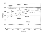
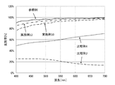
実施例・比較例の蛍光体を用いたテストピースを、60℃、90%RHの恒温槽内に20時間保存し、保存後のテストピースの蛍光体樹脂混合膜をピンセットにより剥離し、露出したAg膜の反射率(%)を測定し、Ag膜の腐食を評価した。実施例1~23及び比較例1~9の結果を表1及び表2に示すと共に、実施例1~16及び比較例1~4の結果を図5-図9に示した。
なお、反射率の測定は、分光測色計(コニカミノルタ製「CM-2600d」)を使用して測定した。
実施例1~16及び比較例1~4で得た蛍光体をそれぞれ2g秤量し、パイレックス(商標登録)ガラス製のシャーレに薄く広げてのせた。また、純水を10g入れたパイレックス(商標登録)ガラス製のシャーレを用意した。
密閉可能な角型アクリルデシケータ(内容積6.76L)の中に、比較例・実施例で得た蛍光体をのせたシャーレと、純水を入れたシャーレと、ガステック社製拡散式硫化水素測定器GHS-8AT(測定範囲0~125ppm)と、ボタン型温湿度記録計(KHラボラトリー製ハイグロクロン)とを入れて、該デシケータを密閉した。
さらに、30℃に調整された恒温槽(エスペックSH-641)内に、デシケータごと入れて、その状態で10時間硫化水素濃度を測定した。
硫化水素濃度の測定中のアクリルデシケータ内の温度と湿度は、それぞれ概ね30℃、90%RHであった。
結果を図1-図4に示した。
実施例1~23及び比較例1~9の蛍光体の外部量子効率(励起波長450nm)を、日本分光社製FP-6500にて測定した。


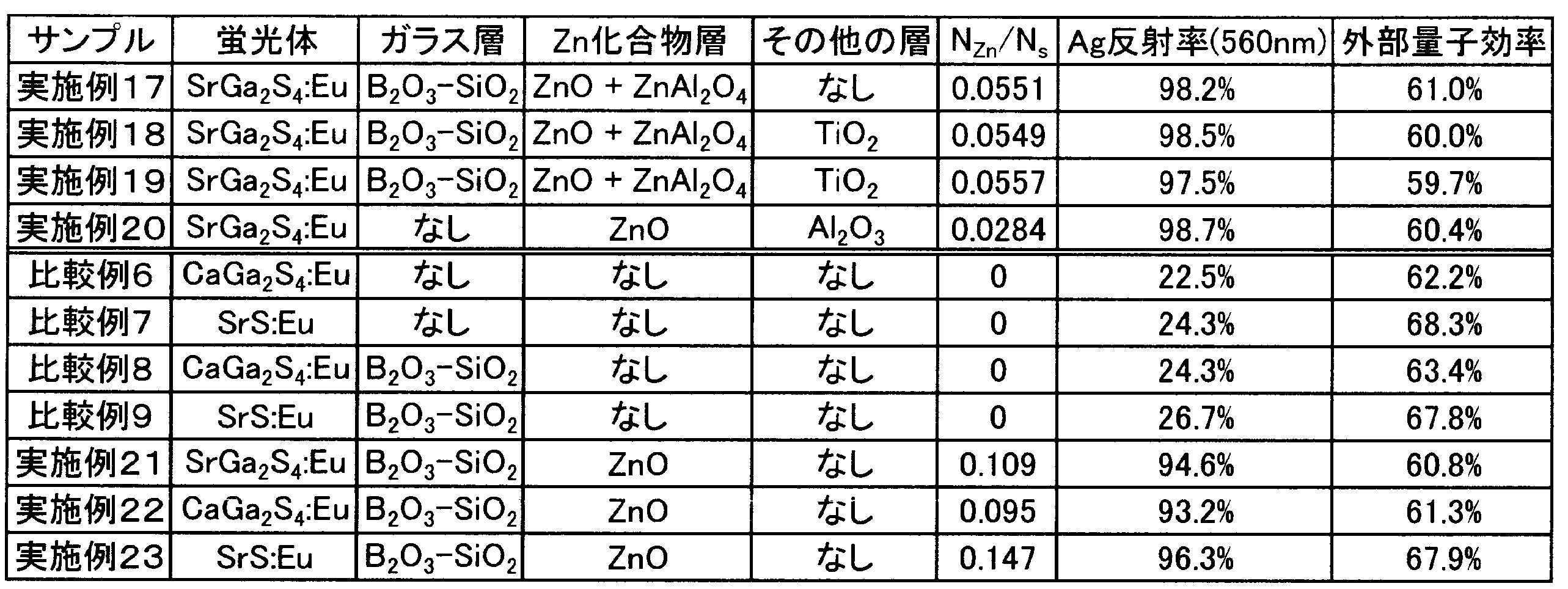

これまでの各種試験と実施例・比較例の結果から、硫黄含有蛍光体の表面に、Zn及びOを含有するZnO化合物を付着させることにより、発生した硫化水素ガスによって例えばAg反射膜が腐食するのを抑制できることが分かった。これは、発生した硫化水素ガスが、硫黄含有蛍光体表面のZnO化合物に化学的に吸着されるためであると考えられる。
また、ステアリン酸亜鉛のような亜鉛の有機酸塩も、同様の効果が得られると考えることができる。
この際、耐水性を高める機能と硫化水素ガスを吸着する機能とを考えると、ZnO化合物層とガラス層の積層順はいずれでもよく、硫黄含有蛍光体の表面からZnO化合物層、ガラス層の順に積層してなる構成であっても、硫黄含有蛍光体の表面からガラス層、ZnO化合物層の順に積層してなる構成であってもよいと考えることができる。
上記実施例及び比較例で得た蛍光体を用いて発光デバイス(LEDパッケージ)を作製し、光束維持率を評価した。
樹脂(シリコーン樹脂、東レ・ダウコーニング社製「OE-6630」(A液:B液=1:4)中に、該樹脂に対して、表3に示す各実施例・比較例で得た蛍光体5wt.%を混合し、自転・公転ミキサー(シンキ-社製「AR-250」)で撹拌、脱泡を60秒ずつ行い、樹脂と蛍光体の混合物を得た。この混合物をLEDリードフレーム(図10参照)内に800μmの厚みで充填した。その後、ゆっくりとシリコーン樹脂を硬化させてLEDパッケージ(サンプル)を作製した(図11、図12参照)。
樹脂(シリコーン樹脂、東レ・ダウコーニング社製「OE-6630」(A液:B液=1:4)中に、該樹脂に対して、表4に示す各実施例で得た蛍光体5wt.%と、表4に示す「添加したZn化合物の濃度」に相当する量のZnO(平均粒径30nm)とを混合し、自転・公転ミキサー(シンキ-社製「AR-250」)で撹拌、脱泡を60秒ずつ行い、樹脂と蛍光体の混合物を得た。この混合物をLEDリードフレーム(図10参照)内に800μmの厚みで充填した。その後、ゆっくりとシリコーン樹脂を硬化させてLEDパッケージ(サンプル)を作製した(図11、図12参照)。
温度85℃、湿度85%RHに設定した小型環境試験器(エスペック社製「SH-641」)内に、実施例24~43・比較例10~17で得たサンプル(LEDパッケージ)を1000時間放置し、放置前の光束を100%とし、放置後の光束変化を調べた。
なお、発光スペクトルおよび強度は、絶対強度補正用ハロゲン光源(オーシャンオプティクス社製「LS-1-CAL」を用いて補正した。
なお、電界放出型走査電子顕微鏡(FE-SEM)の加速電圧は5kV、電流は18μA、ワーキングディスタンス10.00mmとし、ポイント&IDにより定量分析を行った。定量分析の設定値はライフタイム60秒、プロセスタイム3、スペクトルレンジ0から20keVとした。
ピークの検出位置を、Siが1.74keV、Sが2.31keV、Znが1.02keV、Srが1.58keVとし、ZAF補正を用いて、4元素の合計を100wt.%とし、各元素の質量濃度を計算した。


上記実施例24-33及び比較例10-17で作製したLEDパッケージ(サンプル)を、温度85℃、湿度85%RHの小型環境試験器中で1000時間保存した後に取り出したところ、表3の結果となった。
比較例10-17では、反射板が黒色化したことが確認された。硫黄含有蛍光体から発生する硫黄含有ガス、特に硫化水素と、反射板(銀メッキを施した銅合金)とが反応し、例えば銀が硫化銀になって黒色化したことが原因であると考えられる。このように反射板が黒色化すると、LEDパッケージ(サンプル)の発光が低下することになる。また、黒色化した金属部材が、反射板以外の電極であれば、断線や高抵抗化を引き起こすことにもなる。
この点からすると、ZnO化合物被覆硫黄含有蛍光体のZnO化合物は、蛍光体から離脱していても効果を発揮すると考えることができる。よって、例えば、蛍光体と樹脂とを混合し撹拌する過程で、蛍光体の表面側に存在するZnO化合物の一部が蛍光体から離脱した場合でも、硫黄系ガスと金属部材(反射板)が反応するよりも、優先的に硫黄系ガス吸着物質であるZnO化合物に吸着されるものと考えることができる。
Claims (14)
- 母体に硫黄を含む硫黄含有蛍光体の表面側に、Zn及びOを含有するZnO化合物が存在してなる構成を備えたZnO化合物被覆硫黄含有蛍光体。
- 母体に硫黄を含む硫黄含有蛍光体の表面側に、Zn及びOを含有するZnO化合物からなるZnO化合物層を備えたZnO化合物被覆硫黄含有蛍光体。
- Zn及びOを含有するZnO化合物が、ZnO、Zn(OH)2、ZnSO4・nH2O(0≦n≦7)、ZnTi2O4、Zn2Ti3O8、Zn2TiO4、ZnTiO3、ZnBaO2、ZnBa2O3、ZnGa2O4、Zn1.23Ga0.28O2、Zn3GaO4、Zn6Ga2O9、Zn0.125~0.95Mg0.05~0.9O、Zn0.1~0.75Ca0.25~0.9O、ZnSrO2、Zn0.3Al2.4O4、ZnAl2O4、Zn3~7In2O6~10、ZnSnO3、Zn2SnO4及び亜鉛の有機酸塩からなる群から選ばれる一種または二種以上からなることを特徴とする請求項1又は2に記載のZnO化合物被覆硫黄含有蛍光体。
- ガラス組成物を含有するガラス層をさらに備えた請求項1~3の何れかに記載のZnO化合物被覆硫黄含有蛍光体。
- Zn及びOを含有するZnO化合物が、SEM又はTEM観察による平均粒径0.3μm以下の微粒子であることを特徴とする請求項1~4の何れかに記載のZnO化合物被覆硫黄含有蛍光体。
- 硫黄含有蛍光体中のSの原子数量NSに対する、ZnO化合物中のZnの原子数量NZnの比率NZn/NSが0.001以上であることを特徴とする請求項1~5の何れかに記載のZnO化合物被覆硫黄含有蛍光体。
- スピネル型結晶構造を有し、且つ0.1μm未満の粒径を有する微粒子が、前記ZnO化合物又はZnO化合物層の周囲に存在することを特徴とする請求項1~6の何れかに記載のZnO化合物被覆硫黄含有蛍光体。
- スピネル型結晶構造を有し、且つ0.1μm未満の粒径を有する微粒子を含むスピネル層が、前記ZnO化合物又はZnO化合物層と接触するように備えた請求項1~7の何れかに記載のZnO化合物被覆硫黄含有蛍光体。
- Ti、Zn、Mg、Ca、Sr、Ba、Al、Ga、In、Sn、Zr及びYからなる群から選ばれる一種の水酸化物、酸化物又はフッ化物、或いはそれら二種以上の混合物を含有する耐水層をさらに備えた請求項1~8の何れかに記載のZnO化合物被覆硫黄含有蛍光体。
- 少なくとも1つのLEDチップと、少なくとも一つの蛍光体とを備えており、
LEDから発せられる光の少なくとも一部を蛍光体が吸収し、LEDから発せられる光と、蛍光体から発せられる光が混合された光を得る波長変換型発光素子であり、
少なくとも一つの蛍光体が、請求項1~9の何れかに記載のZnO化合物被覆硫黄含有蛍光体であることを特徴とする波長変換型発光素子。 - 請求項10記載の波長変換型発光素子を備えた照明装置。
- 請求項10記載の波長変換型発光素子を備えた画像表示装置。
- 固体発光素子と、硫黄系ガスと反応する金属部材と、蛍光体含有層とを備えた発光デバイスであって、
該蛍光体含有層は、請求項1~9の何れかに記載のZnO化合物被覆硫黄含有蛍光体を樹脂に配合して形成されたものであることを特徴とする発光デバイス。 - 固体発光素子と、硫黄系ガスと反応する金属部材と、蛍光体含有層とを備えた発光デバイスであって、
該蛍光体含有層は、請求項1~9の何れかに記載のZnO化合物被覆硫黄含有蛍光体とZnO化合物とが樹脂中に散在した構成を備えていることを特徴とする発光デバイス。
Priority Applications (5)
| Application Number | Priority Date | Filing Date | Title |
|---|---|---|---|
| JP2012547859A JP5466771B2 (ja) | 2010-12-09 | 2011-12-06 | ZnO化合物被覆硫黄含有蛍光体 |
| EP11846747.1A EP2650343B1 (en) | 2010-12-09 | 2011-12-06 | Sulfur-containing phosphor coated with zno compound |
| CN201180049156.3A CN103154192B (zh) | 2010-12-09 | 2011-12-06 | 有ZnO化合物覆盖的含硫荧光体 |
| KR1020137004807A KR101482674B1 (ko) | 2010-12-09 | 2011-12-06 | ZnO 화합물 피복 황 함유 형광체 |
| US13/991,521 US9312454B2 (en) | 2010-12-09 | 2011-12-06 | Sulfur-containing phosphor coated with ZnO compound |
Applications Claiming Priority (2)
| Application Number | Priority Date | Filing Date | Title |
|---|---|---|---|
| JP2010274532 | 2010-12-09 | ||
| JP2010-274532 | 2010-12-09 |
Publications (1)
| Publication Number | Publication Date |
|---|---|
| WO2012077656A1 true WO2012077656A1 (ja) | 2012-06-14 |
Family
ID=46207144
Family Applications (1)
| Application Number | Title | Priority Date | Filing Date |
|---|---|---|---|
| PCT/JP2011/078127 Ceased WO2012077656A1 (ja) | 2010-12-09 | 2011-12-06 | ZnO化合物被覆硫黄含有蛍光体 |
Country Status (7)
| Country | Link |
|---|---|
| US (1) | US9312454B2 (ja) |
| EP (1) | EP2650343B1 (ja) |
| JP (1) | JP5466771B2 (ja) |
| KR (1) | KR101482674B1 (ja) |
| CN (1) | CN103154192B (ja) |
| TW (1) | TWI466982B (ja) |
| WO (1) | WO2012077656A1 (ja) |
Cited By (21)
| Publication number | Priority date | Publication date | Assignee | Title |
|---|---|---|---|---|
| WO2013084921A1 (ja) * | 2011-12-07 | 2013-06-13 | デクセリアルズ株式会社 | 被覆蛍光体及び被覆蛍光体の製造方法 |
| WO2014017334A1 (ja) * | 2012-07-25 | 2014-01-30 | デクセリアルズ株式会社 | 蛍光体シート |
| WO2014021353A1 (ja) * | 2012-08-02 | 2014-02-06 | 株式会社日本セラテック | 蛍光体材料および発光装置 |
| JP2014045182A (ja) * | 2012-08-02 | 2014-03-13 | Nihon Ceratec Co Ltd | 発光装置 |
| WO2014065292A1 (ja) * | 2012-10-23 | 2014-05-01 | 三井金属鉱業株式会社 | 蛍光体、led発光素子及び光源装置 |
| JP2015063619A (ja) * | 2013-09-25 | 2015-04-09 | 三井金属鉱業株式会社 | 蛍光体 |
| WO2015146231A1 (ja) * | 2014-03-27 | 2015-10-01 | 三井金属鉱業株式会社 | 蛍光体及びその用途 |
| JP2016074798A (ja) * | 2014-10-04 | 2016-05-12 | 国立研究開発法人産業技術総合研究所 | 応力消光材料及び応力消光体、並びに応力消光材料の製造方法 |
| JP2016515145A (ja) * | 2013-02-25 | 2016-05-26 | コーニンクレッカ フィリップス エヌ ヴェKoninklijke Philips N.V. | コーティングされた発光粒子、発光変換素子、光源、照明機器、およびコーティングされた発光粒子を製造する方法 |
| JP2016194088A (ja) * | 2016-07-12 | 2016-11-17 | デクセリアルズ株式会社 | 被覆蛍光体の製造方法 |
| JP2017052927A (ja) * | 2015-03-30 | 2017-03-16 | 日亜化学工業株式会社 | 蛍光体粒子及びその製造方法並びに発光装置 |
| JP2017168581A (ja) * | 2016-03-15 | 2017-09-21 | 日亜化学工業株式会社 | 発光装置の製造方法 |
| US9853191B2 (en) | 2015-12-10 | 2017-12-26 | Nichia Corporation | Light emitting device manufacturing method |
| WO2018061553A1 (ja) * | 2016-09-30 | 2018-04-05 | デクセリアルズ株式会社 | 発光装置、及び発光装置の製造方法 |
| WO2019003927A1 (ja) * | 2017-06-29 | 2019-01-03 | パナソニックIpマネジメント株式会社 | 波長変換部材及び光源 |
| WO2019065193A1 (ja) * | 2017-09-28 | 2019-04-04 | パナソニックIpマネジメント株式会社 | 波長変換部材及び光源 |
| WO2019107080A1 (ja) | 2017-11-30 | 2019-06-06 | デクセリアルズ株式会社 | 被覆蛍光体、その製造方法、並びに、蛍光体シート、及び発光装置 |
| JP2020500244A (ja) * | 2016-10-31 | 2020-01-09 | インテマティックス・コーポレーションIntematix Corporation | コーティング付き狭帯域緑色蛍光体 |
| KR20200090806A (ko) | 2017-11-30 | 2020-07-29 | 데쿠세리아루즈 가부시키가이샤 | 피복 형광체, 그 제조 방법, 그리고, 형광체 시트, 및 발광 장치 |
| US10899965B2 (en) | 2015-03-30 | 2021-01-26 | Nichia Corporation | Fluorescent material particles, method for producing the same, and light emitting device |
| WO2023189046A1 (ja) * | 2022-03-31 | 2023-10-05 | 三井金属鉱業株式会社 | 蛍光体及びその製造方法 |
Families Citing this family (16)
| Publication number | Priority date | Publication date | Assignee | Title |
|---|---|---|---|---|
| JP5720359B2 (ja) * | 2011-03-28 | 2015-05-20 | 日亜化学工業株式会社 | 発光装置 |
| CN105038776A (zh) * | 2015-06-18 | 2015-11-11 | 北京宇极科技发展有限公司 | 锰(Mn4+)掺杂的氟化物荧光粉体材料的制备及表面改性的方法 |
| CN105219381A (zh) * | 2015-10-26 | 2016-01-06 | 陕西光电科技有限公司 | 一种稀土掺杂的硫代镓酸盐荧光粉材料及制备方法 |
| JP6447557B2 (ja) | 2016-03-24 | 2019-01-09 | 日亜化学工業株式会社 | 発光装置の製造方法 |
| CN108231979B (zh) * | 2017-01-24 | 2020-03-31 | 江苏博睿光电有限公司 | 一种红外led光源 |
| CN108630794B (zh) * | 2017-03-22 | 2020-05-19 | 江苏博睿光电有限公司 | 一种白光发光装置 |
| US11426708B2 (en) | 2020-03-02 | 2022-08-30 | King Abdullah University Of Science And Technology | Potassium-promoted red mud as a catalyst for forming hydrocarbons from carbon dioxide |
| US11420915B2 (en) | 2020-06-11 | 2022-08-23 | Saudi Arabian Oil Company | Red mud as a catalyst for the isomerization of olefins |
| US11495814B2 (en) | 2020-06-17 | 2022-11-08 | Saudi Arabian Oil Company | Utilizing black powder for electrolytes for flow batteries |
| US12000056B2 (en) | 2020-06-18 | 2024-06-04 | Saudi Arabian Oil Company | Tandem electrolysis cell |
| US11814289B2 (en) | 2021-01-04 | 2023-11-14 | Saudi Arabian Oil Company | Black powder catalyst for hydrogen production via steam reforming |
| US11820658B2 (en) | 2021-01-04 | 2023-11-21 | Saudi Arabian Oil Company | Black powder catalyst for hydrogen production via autothermal reforming |
| US11427519B2 (en) | 2021-01-04 | 2022-08-30 | Saudi Arabian Oil Company | Acid modified red mud as a catalyst for olefin isomerization |
| US11718522B2 (en) | 2021-01-04 | 2023-08-08 | Saudi Arabian Oil Company | Black powder catalyst for hydrogen production via bi-reforming |
| US11724943B2 (en) | 2021-01-04 | 2023-08-15 | Saudi Arabian Oil Company | Black powder catalyst for hydrogen production via dry reforming |
| US12018392B2 (en) | 2022-01-03 | 2024-06-25 | Saudi Arabian Oil Company | Methods for producing syngas from H2S and CO2 in an electrochemical cell |
Citations (18)
| Publication number | Priority date | Publication date | Assignee | Title |
|---|---|---|---|---|
| JPH02155983A (ja) * | 1988-12-08 | 1990-06-15 | Kasei Optonix Co Ltd | 蛍光体および蛍光体の表面処理方法 |
| JPH02308892A (ja) * | 1989-05-23 | 1990-12-21 | Toshiba Corp | 蛍光体およびその処理方法 |
| JP2002060747A (ja) | 1999-09-27 | 2002-02-26 | Lumileds Lighting Us Llc | 3色型白色光ledランプ |
| JP2002080845A (ja) | 2000-09-08 | 2002-03-22 | Ise Electronics Corp | 低速電子線励起蛍光体及び蛍光表示管 |
| JP2002173675A (ja) | 2000-12-06 | 2002-06-21 | Sanken Electric Co Ltd | 被覆層を有する蛍光粒子及びその製法 |
| JP2002223008A (ja) | 2000-10-17 | 2002-08-09 | Koninkl Philips Electronics Nv | 発光素子 |
| JP2003041250A (ja) | 2001-07-27 | 2003-02-13 | Noritake Itron Corp | 蛍光体 |
| JP2003268368A (ja) * | 2002-03-19 | 2003-09-25 | Nippon Shokubai Co Ltd | 紫外線発光体および紫外線発光体用酸化亜鉛粒子 |
| JP2004250705A (ja) | 2003-02-20 | 2004-09-09 | Osram Opto Semiconductors Gmbh | 被覆された発光物質、該発光物質を含む発光装置および該発光物質の製造法 |
| JP2005082788A (ja) | 2003-09-11 | 2005-03-31 | Nichia Chem Ind Ltd | 発光装置、発光素子用蛍光体および発光素子用蛍光体の製造方法 |
| JP2006028458A (ja) | 2004-07-21 | 2006-02-02 | Matsushita Electric Ind Co Ltd | 蛍光体の製造方法、蛍光体、蛍光ランプ及び照明器具 |
| JP2007056267A (ja) | 2005-08-23 | 2007-03-08 | Samsung Electro Mech Co Ltd | 複合蛍光体粉末、及びこれを用いた発光装置並びに複合蛍光体粉末の製造方法 |
| JP2007146008A (ja) * | 2005-11-28 | 2007-06-14 | Kyocera Corp | 蛍光体及び波長変換器並びに発光装置 |
| JP2007197612A (ja) * | 2006-01-27 | 2007-08-09 | Kyocera Corp | 蛍光体及び波長変換器並びに発光装置 |
| JP2007214579A (ja) | 2006-01-16 | 2007-08-23 | Philips Lumileds Lightng Co Llc | 蛍光体変換発光デバイス |
| JP2008007779A (ja) | 2006-06-28 | 2008-01-17 | Seoul Semiconductor Co Ltd | 蛍光体及びその製造方法並びに発光ダイオード |
| JP2009013186A (ja) | 2007-06-29 | 2009-01-22 | Mitsubishi Chemicals Corp | 被覆蛍光体粒子、被覆蛍光体粒子の製造方法、蛍光体含有組成物、発光装置、画像表示装置、および照明装置 |
| JP2009526089A (ja) * | 2005-12-01 | 2009-07-16 | サーノフ コーポレーション | 湿気保護蛍光体およびled照明デバイス |
Family Cites Families (17)
| Publication number | Priority date | Publication date | Assignee | Title |
|---|---|---|---|---|
| DE2747509A1 (de) * | 1977-10-22 | 1979-04-26 | Riedel De Haen Ag | Verfahren zum schutz von fluoreszierenden bzw. phosphoreszierenden leuchtpigmenten auf basis von zinksulfiden bzw. zink/cadmiumsulfiden gegen vergrauung |
| JPS6014054B2 (ja) * | 1982-12-09 | 1985-04-11 | 武藤 平八郎 | 螢光体 |
| JP3007893B2 (ja) * | 1990-07-09 | 2000-02-07 | 化成オプトニクス株式会社 | 低速電子線用発光組成物 |
| JP3283332B2 (ja) | 1993-04-08 | 2002-05-20 | 新日本製鐵株式会社 | 撚り線加工性の優れた高強度極細鋼線およびその製造方法 |
| US6197218B1 (en) * | 1997-02-24 | 2001-03-06 | Superior Micropowders Llc | Photoluminescent phosphor powders, methods for making phosphor powders and devices incorporating same |
| US6069439A (en) * | 1997-03-31 | 2000-05-30 | Kabushiki Kaisha Toshiba | Phosphor material, method of manufacturing the same and display device |
| US5985173A (en) * | 1997-11-18 | 1999-11-16 | Gray; Henry F. | Phosphors having a semiconductor host surrounded by a shell |
| JP4077170B2 (ja) * | 2000-09-21 | 2008-04-16 | シャープ株式会社 | 半導体発光装置 |
| US20080032415A1 (en) * | 2004-06-22 | 2008-02-07 | Junji Nishigaki | Fluorescence Detection Method |
| JP2006299118A (ja) * | 2005-04-21 | 2006-11-02 | Noritake Itron Corp | 低速電子線用蛍光体、その製造方法および蛍光表示管 |
| CN101336479A (zh) | 2005-12-01 | 2008-12-31 | 沙诺夫公司 | 防潮磷光体和led发光器件 |
| CN101370907A (zh) * | 2006-01-16 | 2009-02-18 | 皇家飞利浦电子股份有限公司 | 具有含Eu的磷光体材料的发光器件 |
| US7713442B2 (en) | 2006-10-03 | 2010-05-11 | Lightscape Materials, Inc. | Metal silicate halide phosphors and LED lighting devices using the same |
| US20080185600A1 (en) | 2007-02-02 | 2008-08-07 | World Properties, Inc. | Phosphor particles with plural coatings for LEDs |
| KR20090002982A (ko) * | 2007-07-05 | 2009-01-09 | 엘지전자 주식회사 | 플라즈마 디스플레이 패널 |
| US8030843B2 (en) * | 2008-07-14 | 2011-10-04 | Wisys Technology Foundation | Quantum dot phosphors for solid-state lighting devices |
| CN101775278B (zh) * | 2010-01-28 | 2013-10-16 | 海洋王照明科技股份有限公司 | 胶体包覆荧光粉及其制备方法 |
-
2011
- 2011-12-06 US US13/991,521 patent/US9312454B2/en active Active
- 2011-12-06 KR KR1020137004807A patent/KR101482674B1/ko active Active
- 2011-12-06 EP EP11846747.1A patent/EP2650343B1/en active Active
- 2011-12-06 WO PCT/JP2011/078127 patent/WO2012077656A1/ja not_active Ceased
- 2011-12-06 JP JP2012547859A patent/JP5466771B2/ja active Active
- 2011-12-06 CN CN201180049156.3A patent/CN103154192B/zh active Active
- 2011-12-08 TW TW100145237A patent/TWI466982B/zh active
Patent Citations (18)
| Publication number | Priority date | Publication date | Assignee | Title |
|---|---|---|---|---|
| JPH02155983A (ja) * | 1988-12-08 | 1990-06-15 | Kasei Optonix Co Ltd | 蛍光体および蛍光体の表面処理方法 |
| JPH02308892A (ja) * | 1989-05-23 | 1990-12-21 | Toshiba Corp | 蛍光体およびその処理方法 |
| JP2002060747A (ja) | 1999-09-27 | 2002-02-26 | Lumileds Lighting Us Llc | 3色型白色光ledランプ |
| JP2002080845A (ja) | 2000-09-08 | 2002-03-22 | Ise Electronics Corp | 低速電子線励起蛍光体及び蛍光表示管 |
| JP2002223008A (ja) | 2000-10-17 | 2002-08-09 | Koninkl Philips Electronics Nv | 発光素子 |
| JP2002173675A (ja) | 2000-12-06 | 2002-06-21 | Sanken Electric Co Ltd | 被覆層を有する蛍光粒子及びその製法 |
| JP2003041250A (ja) | 2001-07-27 | 2003-02-13 | Noritake Itron Corp | 蛍光体 |
| JP2003268368A (ja) * | 2002-03-19 | 2003-09-25 | Nippon Shokubai Co Ltd | 紫外線発光体および紫外線発光体用酸化亜鉛粒子 |
| JP2004250705A (ja) | 2003-02-20 | 2004-09-09 | Osram Opto Semiconductors Gmbh | 被覆された発光物質、該発光物質を含む発光装置および該発光物質の製造法 |
| JP2005082788A (ja) | 2003-09-11 | 2005-03-31 | Nichia Chem Ind Ltd | 発光装置、発光素子用蛍光体および発光素子用蛍光体の製造方法 |
| JP2006028458A (ja) | 2004-07-21 | 2006-02-02 | Matsushita Electric Ind Co Ltd | 蛍光体の製造方法、蛍光体、蛍光ランプ及び照明器具 |
| JP2007056267A (ja) | 2005-08-23 | 2007-03-08 | Samsung Electro Mech Co Ltd | 複合蛍光体粉末、及びこれを用いた発光装置並びに複合蛍光体粉末の製造方法 |
| JP2007146008A (ja) * | 2005-11-28 | 2007-06-14 | Kyocera Corp | 蛍光体及び波長変換器並びに発光装置 |
| JP2009526089A (ja) * | 2005-12-01 | 2009-07-16 | サーノフ コーポレーション | 湿気保護蛍光体およびled照明デバイス |
| JP2007214579A (ja) | 2006-01-16 | 2007-08-23 | Philips Lumileds Lightng Co Llc | 蛍光体変換発光デバイス |
| JP2007197612A (ja) * | 2006-01-27 | 2007-08-09 | Kyocera Corp | 蛍光体及び波長変換器並びに発光装置 |
| JP2008007779A (ja) | 2006-06-28 | 2008-01-17 | Seoul Semiconductor Co Ltd | 蛍光体及びその製造方法並びに発光ダイオード |
| JP2009013186A (ja) | 2007-06-29 | 2009-01-22 | Mitsubishi Chemicals Corp | 被覆蛍光体粒子、被覆蛍光体粒子の製造方法、蛍光体含有組成物、発光装置、画像表示装置、および照明装置 |
Non-Patent Citations (1)
| Title |
|---|
| See also references of EP2650343A4 |
Cited By (47)
| Publication number | Priority date | Publication date | Assignee | Title |
|---|---|---|---|---|
| WO2013084921A1 (ja) * | 2011-12-07 | 2013-06-13 | デクセリアルズ株式会社 | 被覆蛍光体及び被覆蛍光体の製造方法 |
| JP2013119581A (ja) * | 2011-12-07 | 2013-06-17 | Dexerials Corp | 被覆蛍光体及び被覆蛍光体の製造方法 |
| US9540563B2 (en) | 2011-12-07 | 2017-01-10 | Dexerials Corporation | Coated phosphor and method for producing coated phosphor |
| CN104471024A (zh) * | 2012-07-25 | 2015-03-25 | 迪睿合电子材料有限公司 | 荧光体片 |
| TWI680180B (zh) * | 2012-07-25 | 2019-12-21 | 日商迪睿合股份有限公司 | 被覆螢光體 |
| KR102120951B1 (ko) * | 2012-07-25 | 2020-06-09 | 데쿠세리아루즈 가부시키가이샤 | 형광체 시트 |
| US9850427B2 (en) | 2012-07-25 | 2017-12-26 | Dexerials Corporation | Phosphor sheet |
| TWI596189B (zh) * | 2012-07-25 | 2017-08-21 | 迪睿合股份有限公司 | 螢光體片 |
| JP2014024918A (ja) * | 2012-07-25 | 2014-02-06 | Dexerials Corp | 蛍光体シート |
| WO2014017334A1 (ja) * | 2012-07-25 | 2014-01-30 | デクセリアルズ株式会社 | 蛍光体シート |
| EP2878646A4 (en) * | 2012-07-25 | 2016-08-10 | Dexerials Corp | PHOSPHOR LAYER |
| KR20150038078A (ko) * | 2012-07-25 | 2015-04-08 | 데쿠세리아루즈 가부시키가이샤 | 형광체 시트 |
| JP2014045182A (ja) * | 2012-08-02 | 2014-03-13 | Nihon Ceratec Co Ltd | 発光装置 |
| JP2014043569A (ja) * | 2012-08-02 | 2014-03-13 | Nihon Ceratec Co Ltd | 蛍光体材料および発光装置 |
| WO2014021353A1 (ja) * | 2012-08-02 | 2014-02-06 | 株式会社日本セラテック | 蛍光体材料および発光装置 |
| US9394478B2 (en) | 2012-10-23 | 2016-07-19 | Mitsui Mining & Smelting Co., Ltd. | Phosphor, LED light-emission element, and light source device |
| WO2014065292A1 (ja) * | 2012-10-23 | 2014-05-01 | 三井金属鉱業株式会社 | 蛍光体、led発光素子及び光源装置 |
| CN104471025A (zh) * | 2012-10-23 | 2015-03-25 | 三井金属矿业株式会社 | 荧光体、led发光元件和光源装置 |
| KR101499150B1 (ko) * | 2012-10-23 | 2015-03-05 | 미쓰이금속광업주식회사 | 형광체, led 발광 소자 및 광원 장치 |
| JP5575994B1 (ja) * | 2012-10-23 | 2014-08-20 | 三井金属鉱業株式会社 | 蛍光体、led発光素子及び光源装置 |
| JP2018111830A (ja) * | 2013-02-25 | 2018-07-19 | コーニンクレッカ フィリップス エヌ ヴェKoninklijke Philips N.V. | コーティングされた発光粒子、発光変換素子、光源、照明機器、およびコーティングされた発光粒子を製造する方法 |
| JP2016515145A (ja) * | 2013-02-25 | 2016-05-26 | コーニンクレッカ フィリップス エヌ ヴェKoninklijke Philips N.V. | コーティングされた発光粒子、発光変換素子、光源、照明機器、およびコーティングされた発光粒子を製造する方法 |
| JP2020073655A (ja) * | 2013-02-25 | 2020-05-14 | コーニンクレッカ フィリップス エヌ ヴェKoninklijke Philips N.V. | コーティングされた発光粒子、発光変換素子、光源、照明機器、およびコーティングされた発光粒子を製造する方法 |
| US10875005B2 (en) | 2013-02-25 | 2020-12-29 | Lumileds Llc | Coated luminescent particle, a luminescent converter element, a light source, a luminaire and a method of manufacturing a coated luminescent particle |
| JP2015063619A (ja) * | 2013-09-25 | 2015-04-09 | 三井金属鉱業株式会社 | 蛍光体 |
| KR20160114640A (ko) | 2014-03-27 | 2016-10-05 | 미쓰이금속광업주식회사 | 형광체 및 그 용도 |
| WO2015146231A1 (ja) * | 2014-03-27 | 2015-10-01 | 三井金属鉱業株式会社 | 蛍光体及びその用途 |
| JP5796148B1 (ja) * | 2014-03-27 | 2015-10-21 | 三井金属鉱業株式会社 | 蛍光体及びその用途 |
| US10550321B2 (en) | 2014-03-27 | 2020-02-04 | Mitsui Mining & Smelting Co., Ltd. | Phosphor and use thereof |
| JP2016074798A (ja) * | 2014-10-04 | 2016-05-12 | 国立研究開発法人産業技術総合研究所 | 応力消光材料及び応力消光体、並びに応力消光材料の製造方法 |
| JP2017052927A (ja) * | 2015-03-30 | 2017-03-16 | 日亜化学工業株式会社 | 蛍光体粒子及びその製造方法並びに発光装置 |
| US10899965B2 (en) | 2015-03-30 | 2021-01-26 | Nichia Corporation | Fluorescent material particles, method for producing the same, and light emitting device |
| US10230025B2 (en) | 2015-12-10 | 2019-03-12 | Nichia Corporation | Light emitting device having wavelength conversion layer with filling particles |
| US9853191B2 (en) | 2015-12-10 | 2017-12-26 | Nichia Corporation | Light emitting device manufacturing method |
| JP2017168581A (ja) * | 2016-03-15 | 2017-09-21 | 日亜化学工業株式会社 | 発光装置の製造方法 |
| JP2016194088A (ja) * | 2016-07-12 | 2016-11-17 | デクセリアルズ株式会社 | 被覆蛍光体の製造方法 |
| WO2018061553A1 (ja) * | 2016-09-30 | 2018-04-05 | デクセリアルズ株式会社 | 発光装置、及び発光装置の製造方法 |
| JP2020500244A (ja) * | 2016-10-31 | 2020-01-09 | インテマティックス・コーポレーションIntematix Corporation | コーティング付き狭帯域緑色蛍光体 |
| US11015116B2 (en) | 2016-10-31 | 2021-05-25 | Intematix Corporation | Coated narrow band green phosphor |
| WO2019003927A1 (ja) * | 2017-06-29 | 2019-01-03 | パナソニックIpマネジメント株式会社 | 波長変換部材及び光源 |
| WO2019065193A1 (ja) * | 2017-09-28 | 2019-04-04 | パナソニックIpマネジメント株式会社 | 波長変換部材及び光源 |
| JPWO2019065193A1 (ja) * | 2017-09-28 | 2020-11-26 | パナソニックIpマネジメント株式会社 | 波長変換部材及び光源 |
| WO2019107080A1 (ja) | 2017-11-30 | 2019-06-06 | デクセリアルズ株式会社 | 被覆蛍光体、その製造方法、並びに、蛍光体シート、及び発光装置 |
| KR20200090806A (ko) | 2017-11-30 | 2020-07-29 | 데쿠세리아루즈 가부시키가이샤 | 피복 형광체, 그 제조 방법, 그리고, 형광체 시트, 및 발광 장치 |
| US11613696B2 (en) | 2017-11-30 | 2023-03-28 | Dexerials Corporation | Coated phosphor, method for producing same, phosphor sheet, and light-emitting device |
| US11795390B2 (en) | 2017-11-30 | 2023-10-24 | Dexerials Corporation | Coated phosphor method for producing same, phosphor sheet, and light-emitting device |
| WO2023189046A1 (ja) * | 2022-03-31 | 2023-10-05 | 三井金属鉱業株式会社 | 蛍光体及びその製造方法 |
Also Published As
| Publication number | Publication date |
|---|---|
| US20130256715A1 (en) | 2013-10-03 |
| TW201231621A (en) | 2012-08-01 |
| TWI466982B (zh) | 2015-01-01 |
| CN103154192A (zh) | 2013-06-12 |
| JPWO2012077656A1 (ja) | 2014-05-19 |
| JP5466771B2 (ja) | 2014-04-09 |
| EP2650343A4 (en) | 2014-07-16 |
| CN103154192B (zh) | 2015-06-17 |
| KR20140002607A (ko) | 2014-01-08 |
| EP2650343A1 (en) | 2013-10-16 |
| KR101482674B1 (ko) | 2015-01-14 |
| US9312454B2 (en) | 2016-04-12 |
| EP2650343B1 (en) | 2016-03-02 |
Similar Documents
| Publication | Publication Date | Title |
|---|---|---|
| JP5466771B2 (ja) | ZnO化合物被覆硫黄含有蛍光体 | |
| JP6122747B2 (ja) | 蛍光体 | |
| KR101496921B1 (ko) | 발광 디바이스 | |
| EP2913380B1 (en) | Phosphor, led light-emission element, and light source device | |
| US10550321B2 (en) | Phosphor and use thereof | |
| JP5756523B2 (ja) | 赤色蛍光体及び発光素子 |
Legal Events
| Date | Code | Title | Description |
|---|---|---|---|
| WWE | Wipo information: entry into national phase |
Ref document number: 201180049156.3 Country of ref document: CN |
|
| 121 | Ep: the epo has been informed by wipo that ep was designated in this application |
Ref document number: 11846747 Country of ref document: EP Kind code of ref document: A1 |
|
| WWE | Wipo information: entry into national phase |
Ref document number: 2012547859 Country of ref document: JP |
|
| ENP | Entry into the national phase |
Ref document number: 20137004807 Country of ref document: KR Kind code of ref document: A |
|
| WWE | Wipo information: entry into national phase |
Ref document number: 2011846747 Country of ref document: EP |
|
| WWE | Wipo information: entry into national phase |
Ref document number: 13991521 Country of ref document: US |
|
| NENP | Non-entry into the national phase |
Ref country code: DE |