WO2012081103A1 - 電動車両の電源装置およびその制御方法 - Google Patents
電動車両の電源装置およびその制御方法 Download PDFInfo
- Publication number
- WO2012081103A1 WO2012081103A1 PCT/JP2010/072650 JP2010072650W WO2012081103A1 WO 2012081103 A1 WO2012081103 A1 WO 2012081103A1 JP 2010072650 W JP2010072650 W JP 2010072650W WO 2012081103 A1 WO2012081103 A1 WO 2012081103A1
- Authority
- WO
- WIPO (PCT)
- Prior art keywords
- power
- charging
- voltage
- storage device
- conversion
- Prior art date
- Legal status (The legal status is an assumption and is not a legal conclusion. Google has not performed a legal analysis and makes no representation as to the accuracy of the status listed.)
- Ceased
Links
Images






Classifications
-
- H—ELECTRICITY
- H02—GENERATION; CONVERSION OR DISTRIBUTION OF ELECTRIC POWER
- H02J—ELECTRIC POWER NETWORKS; CIRCUIT ARRANGEMENTS OR SYSTEMS FOR SUPPLYING OR DISTRIBUTING ELECTRIC POWER; SYSTEMS FOR STORING ELECTRIC ENERGY
- H02J7/00—Circuit arrangements for charging or discharging batteries or for supplying loads from batteries
- H02J7/02—Circuit arrangements for charging or discharging batteries or for supplying loads from batteries for charging batteries from AC mains by converters
-
- B—PERFORMING OPERATIONS; TRANSPORTING
- B60—VEHICLES IN GENERAL
- B60L—PROPULSION OF ELECTRICALLY-PROPELLED VEHICLES; SUPPLYING ELECTRIC POWER FOR AUXILIARY EQUIPMENT OF ELECTRICALLY-PROPELLED VEHICLES; ELECTRODYNAMIC BRAKE SYSTEMS FOR VEHICLES IN GENERAL; MAGNETIC SUSPENSION OR LEVITATION FOR VEHICLES; MONITORING OPERATING VARIABLES OF ELECTRICALLY-PROPELLED VEHICLES; ELECTRIC SAFETY DEVICES FOR ELECTRICALLY-PROPELLED VEHICLES
- B60L1/00—Supplying electric power to auxiliary equipment of vehicles
- B60L1/003—Supplying electric power to auxiliary equipment of vehicles to auxiliary motors, e.g. for pumps, compressors
-
- B—PERFORMING OPERATIONS; TRANSPORTING
- B60—VEHICLES IN GENERAL
- B60L—PROPULSION OF ELECTRICALLY-PROPELLED VEHICLES; SUPPLYING ELECTRIC POWER FOR AUXILIARY EQUIPMENT OF ELECTRICALLY-PROPELLED VEHICLES; ELECTRODYNAMIC BRAKE SYSTEMS FOR VEHICLES IN GENERAL; MAGNETIC SUSPENSION OR LEVITATION FOR VEHICLES; MONITORING OPERATING VARIABLES OF ELECTRICALLY-PROPELLED VEHICLES; ELECTRIC SAFETY DEVICES FOR ELECTRICALLY-PROPELLED VEHICLES
- B60L15/00—Methods, circuits, or devices for controlling the traction-motor speed of electrically-propelled vehicles
- B60L15/007—Physical arrangements or structures of drive train converters specially adapted for the propulsion motors of electric vehicles
-
- B—PERFORMING OPERATIONS; TRANSPORTING
- B60—VEHICLES IN GENERAL
- B60L—PROPULSION OF ELECTRICALLY-PROPELLED VEHICLES; SUPPLYING ELECTRIC POWER FOR AUXILIARY EQUIPMENT OF ELECTRICALLY-PROPELLED VEHICLES; ELECTRODYNAMIC BRAKE SYSTEMS FOR VEHICLES IN GENERAL; MAGNETIC SUSPENSION OR LEVITATION FOR VEHICLES; MONITORING OPERATING VARIABLES OF ELECTRICALLY-PROPELLED VEHICLES; ELECTRIC SAFETY DEVICES FOR ELECTRICALLY-PROPELLED VEHICLES
- B60L15/00—Methods, circuits, or devices for controlling the traction-motor speed of electrically-propelled vehicles
- B60L15/20—Methods, circuits, or devices for controlling the traction-motor speed of electrically-propelled vehicles for control of the vehicle or its driving motor to achieve a desired performance, e.g. speed, torque, programmed variation of speed
- B60L15/2009—Methods, circuits, or devices for controlling the traction-motor speed of electrically-propelled vehicles for control of the vehicle or its driving motor to achieve a desired performance, e.g. speed, torque, programmed variation of speed for braking
-
- B—PERFORMING OPERATIONS; TRANSPORTING
- B60—VEHICLES IN GENERAL
- B60L—PROPULSION OF ELECTRICALLY-PROPELLED VEHICLES; SUPPLYING ELECTRIC POWER FOR AUXILIARY EQUIPMENT OF ELECTRICALLY-PROPELLED VEHICLES; ELECTRODYNAMIC BRAKE SYSTEMS FOR VEHICLES IN GENERAL; MAGNETIC SUSPENSION OR LEVITATION FOR VEHICLES; MONITORING OPERATING VARIABLES OF ELECTRICALLY-PROPELLED VEHICLES; ELECTRIC SAFETY DEVICES FOR ELECTRICALLY-PROPELLED VEHICLES
- B60L50/00—Electric propulsion with power supplied within the vehicle
- B60L50/50—Electric propulsion with power supplied within the vehicle using propulsion power supplied by batteries or fuel cells
- B60L50/60—Electric propulsion with power supplied within the vehicle using propulsion power supplied by batteries or fuel cells using power supplied by batteries
- B60L50/61—Electric propulsion with power supplied within the vehicle using propulsion power supplied by batteries or fuel cells using power supplied by batteries by batteries charged by engine-driven generators, e.g. series hybrid electric vehicles
-
- B—PERFORMING OPERATIONS; TRANSPORTING
- B60—VEHICLES IN GENERAL
- B60L—PROPULSION OF ELECTRICALLY-PROPELLED VEHICLES; SUPPLYING ELECTRIC POWER FOR AUXILIARY EQUIPMENT OF ELECTRICALLY-PROPELLED VEHICLES; ELECTRODYNAMIC BRAKE SYSTEMS FOR VEHICLES IN GENERAL; MAGNETIC SUSPENSION OR LEVITATION FOR VEHICLES; MONITORING OPERATING VARIABLES OF ELECTRICALLY-PROPELLED VEHICLES; ELECTRIC SAFETY DEVICES FOR ELECTRICALLY-PROPELLED VEHICLES
- B60L53/00—Methods of charging batteries, specially adapted for electric vehicles; Charging stations or on-board charging equipment therefor; Exchange of energy storage elements in electric vehicles
- B60L53/10—Methods of charging batteries, specially adapted for electric vehicles; Charging stations or on-board charging equipment therefor; Exchange of energy storage elements in electric vehicles characterised by the energy transfer between the charging station and the vehicle
- B60L53/14—Conductive energy transfer
-
- B—PERFORMING OPERATIONS; TRANSPORTING
- B60—VEHICLES IN GENERAL
- B60L—PROPULSION OF ELECTRICALLY-PROPELLED VEHICLES; SUPPLYING ELECTRIC POWER FOR AUXILIARY EQUIPMENT OF ELECTRICALLY-PROPELLED VEHICLES; ELECTRODYNAMIC BRAKE SYSTEMS FOR VEHICLES IN GENERAL; MAGNETIC SUSPENSION OR LEVITATION FOR VEHICLES; MONITORING OPERATING VARIABLES OF ELECTRICALLY-PROPELLED VEHICLES; ELECTRIC SAFETY DEVICES FOR ELECTRICALLY-PROPELLED VEHICLES
- B60L58/00—Methods or circuit arrangements for monitoring or controlling batteries or fuel cells, specially adapted for electric vehicles
- B60L58/10—Methods or circuit arrangements for monitoring or controlling batteries or fuel cells, specially adapted for electric vehicles for monitoring or controlling batteries
- B60L58/12—Methods or circuit arrangements for monitoring or controlling batteries or fuel cells, specially adapted for electric vehicles for monitoring or controlling batteries responding to state of charge [SoC]
-
- B—PERFORMING OPERATIONS; TRANSPORTING
- B60—VEHICLES IN GENERAL
- B60L—PROPULSION OF ELECTRICALLY-PROPELLED VEHICLES; SUPPLYING ELECTRIC POWER FOR AUXILIARY EQUIPMENT OF ELECTRICALLY-PROPELLED VEHICLES; ELECTRODYNAMIC BRAKE SYSTEMS FOR VEHICLES IN GENERAL; MAGNETIC SUSPENSION OR LEVITATION FOR VEHICLES; MONITORING OPERATING VARIABLES OF ELECTRICALLY-PROPELLED VEHICLES; ELECTRIC SAFETY DEVICES FOR ELECTRICALLY-PROPELLED VEHICLES
- B60L58/00—Methods or circuit arrangements for monitoring or controlling batteries or fuel cells, specially adapted for electric vehicles
- B60L58/10—Methods or circuit arrangements for monitoring or controlling batteries or fuel cells, specially adapted for electric vehicles for monitoring or controlling batteries
- B60L58/18—Methods or circuit arrangements for monitoring or controlling batteries or fuel cells, specially adapted for electric vehicles for monitoring or controlling batteries of two or more battery modules
- B60L58/20—Methods or circuit arrangements for monitoring or controlling batteries or fuel cells, specially adapted for electric vehicles for monitoring or controlling batteries of two or more battery modules having different nominal voltages
-
- B—PERFORMING OPERATIONS; TRANSPORTING
- B60—VEHICLES IN GENERAL
- B60L—PROPULSION OF ELECTRICALLY-PROPELLED VEHICLES; SUPPLYING ELECTRIC POWER FOR AUXILIARY EQUIPMENT OF ELECTRICALLY-PROPELLED VEHICLES; ELECTRODYNAMIC BRAKE SYSTEMS FOR VEHICLES IN GENERAL; MAGNETIC SUSPENSION OR LEVITATION FOR VEHICLES; MONITORING OPERATING VARIABLES OF ELECTRICALLY-PROPELLED VEHICLES; ELECTRIC SAFETY DEVICES FOR ELECTRICALLY-PROPELLED VEHICLES
- B60L2210/00—Converter types
- B60L2210/10—DC to DC converters
-
- B—PERFORMING OPERATIONS; TRANSPORTING
- B60—VEHICLES IN GENERAL
- B60L—PROPULSION OF ELECTRICALLY-PROPELLED VEHICLES; SUPPLYING ELECTRIC POWER FOR AUXILIARY EQUIPMENT OF ELECTRICALLY-PROPELLED VEHICLES; ELECTRODYNAMIC BRAKE SYSTEMS FOR VEHICLES IN GENERAL; MAGNETIC SUSPENSION OR LEVITATION FOR VEHICLES; MONITORING OPERATING VARIABLES OF ELECTRICALLY-PROPELLED VEHICLES; ELECTRIC SAFETY DEVICES FOR ELECTRICALLY-PROPELLED VEHICLES
- B60L2210/00—Converter types
- B60L2210/30—AC to DC converters
-
- B—PERFORMING OPERATIONS; TRANSPORTING
- B60—VEHICLES IN GENERAL
- B60L—PROPULSION OF ELECTRICALLY-PROPELLED VEHICLES; SUPPLYING ELECTRIC POWER FOR AUXILIARY EQUIPMENT OF ELECTRICALLY-PROPELLED VEHICLES; ELECTRODYNAMIC BRAKE SYSTEMS FOR VEHICLES IN GENERAL; MAGNETIC SUSPENSION OR LEVITATION FOR VEHICLES; MONITORING OPERATING VARIABLES OF ELECTRICALLY-PROPELLED VEHICLES; ELECTRIC SAFETY DEVICES FOR ELECTRICALLY-PROPELLED VEHICLES
- B60L2210/00—Converter types
- B60L2210/40—DC to AC converters
-
- B—PERFORMING OPERATIONS; TRANSPORTING
- B60—VEHICLES IN GENERAL
- B60L—PROPULSION OF ELECTRICALLY-PROPELLED VEHICLES; SUPPLYING ELECTRIC POWER FOR AUXILIARY EQUIPMENT OF ELECTRICALLY-PROPELLED VEHICLES; ELECTRODYNAMIC BRAKE SYSTEMS FOR VEHICLES IN GENERAL; MAGNETIC SUSPENSION OR LEVITATION FOR VEHICLES; MONITORING OPERATING VARIABLES OF ELECTRICALLY-PROPELLED VEHICLES; ELECTRIC SAFETY DEVICES FOR ELECTRICALLY-PROPELLED VEHICLES
- B60L2240/00—Control parameters of input or output; Target parameters
- B60L2240/10—Vehicle control parameters
- B60L2240/36—Temperature of vehicle components or parts
-
- B—PERFORMING OPERATIONS; TRANSPORTING
- B60—VEHICLES IN GENERAL
- B60L—PROPULSION OF ELECTRICALLY-PROPELLED VEHICLES; SUPPLYING ELECTRIC POWER FOR AUXILIARY EQUIPMENT OF ELECTRICALLY-PROPELLED VEHICLES; ELECTRODYNAMIC BRAKE SYSTEMS FOR VEHICLES IN GENERAL; MAGNETIC SUSPENSION OR LEVITATION FOR VEHICLES; MONITORING OPERATING VARIABLES OF ELECTRICALLY-PROPELLED VEHICLES; ELECTRIC SAFETY DEVICES FOR ELECTRICALLY-PROPELLED VEHICLES
- B60L2240/00—Control parameters of input or output; Target parameters
- B60L2240/40—Drive Train control parameters
- B60L2240/42—Drive Train control parameters related to electric machines
- B60L2240/423—Torque
-
- B—PERFORMING OPERATIONS; TRANSPORTING
- B60—VEHICLES IN GENERAL
- B60L—PROPULSION OF ELECTRICALLY-PROPELLED VEHICLES; SUPPLYING ELECTRIC POWER FOR AUXILIARY EQUIPMENT OF ELECTRICALLY-PROPELLED VEHICLES; ELECTRODYNAMIC BRAKE SYSTEMS FOR VEHICLES IN GENERAL; MAGNETIC SUSPENSION OR LEVITATION FOR VEHICLES; MONITORING OPERATING VARIABLES OF ELECTRICALLY-PROPELLED VEHICLES; ELECTRIC SAFETY DEVICES FOR ELECTRICALLY-PROPELLED VEHICLES
- B60L2240/00—Control parameters of input or output; Target parameters
- B60L2240/80—Time limits
-
- H—ELECTRICITY
- H02—GENERATION; CONVERSION OR DISTRIBUTION OF ELECTRIC POWER
- H02J—ELECTRIC POWER NETWORKS; CIRCUIT ARRANGEMENTS OR SYSTEMS FOR SUPPLYING OR DISTRIBUTING ELECTRIC POWER; SYSTEMS FOR STORING ELECTRIC ENERGY
- H02J2207/00—Details of circuit arrangements for charging or discharging batteries or supplying loads from batteries
- H02J2207/20—Charging or discharging characterised by the power electronics converter
-
- Y—GENERAL TAGGING OF NEW TECHNOLOGICAL DEVELOPMENTS; GENERAL TAGGING OF CROSS-SECTIONAL TECHNOLOGIES SPANNING OVER SEVERAL SECTIONS OF THE IPC; TECHNICAL SUBJECTS COVERED BY FORMER USPC CROSS-REFERENCE ART COLLECTIONS [XRACs] AND DIGESTS
- Y02—TECHNOLOGIES OR APPLICATIONS FOR MITIGATION OR ADAPTATION AGAINST CLIMATE CHANGE
- Y02T—CLIMATE CHANGE MITIGATION TECHNOLOGIES RELATED TO TRANSPORTATION
- Y02T10/00—Road transport of goods or passengers
- Y02T10/60—Other road transportation technologies with climate change mitigation effect
- Y02T10/62—Hybrid vehicles
-
- Y—GENERAL TAGGING OF NEW TECHNOLOGICAL DEVELOPMENTS; GENERAL TAGGING OF CROSS-SECTIONAL TECHNOLOGIES SPANNING OVER SEVERAL SECTIONS OF THE IPC; TECHNICAL SUBJECTS COVERED BY FORMER USPC CROSS-REFERENCE ART COLLECTIONS [XRACs] AND DIGESTS
- Y02—TECHNOLOGIES OR APPLICATIONS FOR MITIGATION OR ADAPTATION AGAINST CLIMATE CHANGE
- Y02T—CLIMATE CHANGE MITIGATION TECHNOLOGIES RELATED TO TRANSPORTATION
- Y02T10/00—Road transport of goods or passengers
- Y02T10/60—Other road transportation technologies with climate change mitigation effect
- Y02T10/64—Electric machine technologies in electromobility
-
- Y—GENERAL TAGGING OF NEW TECHNOLOGICAL DEVELOPMENTS; GENERAL TAGGING OF CROSS-SECTIONAL TECHNOLOGIES SPANNING OVER SEVERAL SECTIONS OF THE IPC; TECHNICAL SUBJECTS COVERED BY FORMER USPC CROSS-REFERENCE ART COLLECTIONS [XRACs] AND DIGESTS
- Y02—TECHNOLOGIES OR APPLICATIONS FOR MITIGATION OR ADAPTATION AGAINST CLIMATE CHANGE
- Y02T—CLIMATE CHANGE MITIGATION TECHNOLOGIES RELATED TO TRANSPORTATION
- Y02T10/00—Road transport of goods or passengers
- Y02T10/60—Other road transportation technologies with climate change mitigation effect
- Y02T10/70—Energy storage systems for electromobility, e.g. batteries
-
- Y—GENERAL TAGGING OF NEW TECHNOLOGICAL DEVELOPMENTS; GENERAL TAGGING OF CROSS-SECTIONAL TECHNOLOGIES SPANNING OVER SEVERAL SECTIONS OF THE IPC; TECHNICAL SUBJECTS COVERED BY FORMER USPC CROSS-REFERENCE ART COLLECTIONS [XRACs] AND DIGESTS
- Y02—TECHNOLOGIES OR APPLICATIONS FOR MITIGATION OR ADAPTATION AGAINST CLIMATE CHANGE
- Y02T—CLIMATE CHANGE MITIGATION TECHNOLOGIES RELATED TO TRANSPORTATION
- Y02T10/00—Road transport of goods or passengers
- Y02T10/60—Other road transportation technologies with climate change mitigation effect
- Y02T10/7072—Electromobility specific charging systems or methods for batteries, ultracapacitors, supercapacitors or double-layer capacitors
-
- Y—GENERAL TAGGING OF NEW TECHNOLOGICAL DEVELOPMENTS; GENERAL TAGGING OF CROSS-SECTIONAL TECHNOLOGIES SPANNING OVER SEVERAL SECTIONS OF THE IPC; TECHNICAL SUBJECTS COVERED BY FORMER USPC CROSS-REFERENCE ART COLLECTIONS [XRACs] AND DIGESTS
- Y02—TECHNOLOGIES OR APPLICATIONS FOR MITIGATION OR ADAPTATION AGAINST CLIMATE CHANGE
- Y02T—CLIMATE CHANGE MITIGATION TECHNOLOGIES RELATED TO TRANSPORTATION
- Y02T10/00—Road transport of goods or passengers
- Y02T10/60—Other road transportation technologies with climate change mitigation effect
- Y02T10/72—Electric energy management in electromobility
-
- Y—GENERAL TAGGING OF NEW TECHNOLOGICAL DEVELOPMENTS; GENERAL TAGGING OF CROSS-SECTIONAL TECHNOLOGIES SPANNING OVER SEVERAL SECTIONS OF THE IPC; TECHNICAL SUBJECTS COVERED BY FORMER USPC CROSS-REFERENCE ART COLLECTIONS [XRACs] AND DIGESTS
- Y02—TECHNOLOGIES OR APPLICATIONS FOR MITIGATION OR ADAPTATION AGAINST CLIMATE CHANGE
- Y02T—CLIMATE CHANGE MITIGATION TECHNOLOGIES RELATED TO TRANSPORTATION
- Y02T90/00—Enabling technologies or technologies with a potential or indirect contribution to GHG emissions mitigation
- Y02T90/10—Technologies relating to charging of electric vehicles
- Y02T90/12—Electric charging stations
-
- Y—GENERAL TAGGING OF NEW TECHNOLOGICAL DEVELOPMENTS; GENERAL TAGGING OF CROSS-SECTIONAL TECHNOLOGIES SPANNING OVER SEVERAL SECTIONS OF THE IPC; TECHNICAL SUBJECTS COVERED BY FORMER USPC CROSS-REFERENCE ART COLLECTIONS [XRACs] AND DIGESTS
- Y02—TECHNOLOGIES OR APPLICATIONS FOR MITIGATION OR ADAPTATION AGAINST CLIMATE CHANGE
- Y02T—CLIMATE CHANGE MITIGATION TECHNOLOGIES RELATED TO TRANSPORTATION
- Y02T90/00—Enabling technologies or technologies with a potential or indirect contribution to GHG emissions mitigation
- Y02T90/10—Technologies relating to charging of electric vehicles
- Y02T90/14—Plug-in electric vehicles
Definitions
- the present invention relates to a power supply device for an electric vehicle and a control method therefor, and more particularly to charge control for a power storage device in an electric vehicle configured to be able to charge an in-vehicle power storage device using an external power source.
- the on-vehicle power storage device is connected to a power source outside the vehicle (hereinafter also simply referred to as “external power source”).
- a configuration for charging has been proposed.
- charging of the power storage device by the external power supply is also referred to as “external charging”.
- a high-voltage power storage device for example, a main battery
- a low-voltage power storage device for example, an auxiliary battery
- a configuration in which the apparatus is mounted is common.
- Patent Document 1 describes a configuration for achieving both improvement in charging efficiency and ensuring operation of the auxiliary load system during external charging. Specifically, by external charging so that both external charging and auxiliary load system operation are possible even with relay 150C (system main relay) between traveling motor 30 and main battery 10 turned off. A configuration for providing a charging path for the main battery is described.
- Patent Document 2 Japanese Patent Application Laid-Open No. 9-009417 (Patent Document 2) and Japanese Patent Application Laid-Open No. 9-065509 (Patent Document 3) describe techniques for downsizing a charger mounted on an electric vehicle. . Specifically, the charger for the main battery and the auxiliary battery can be shared, thereby reducing the size and cost of the charger.
- JP 2009-225587 A JP-A-9-009417 JP-A-9-065509
- the DC / DC converter 60 steps down the output voltage of the main battery 10 to ensure the charging power of the auxiliary battery 70, that is, the power consumption of the auxiliary load 80. can do.
- Patent Documents 2 and 3 by sharing the charger for the main battery B1 and the auxiliary battery B2, the charger can be reduced in size and cost. Specifically, the charger operates to perform power conversion in the opposite direction to that when converting power from the commercial AC power supply AC to charge power of the main battery B1 when charging the auxiliary battery B2. .
- the charging voltage of the auxiliary battery B2 is generated by stepping down the output voltage from the charger by the voltage adjusting circuit 8. As with the DC / DC converter 60 of Patent Document 1, it is understood that this voltage adjustment circuit 8 needs to have a relatively large capacity in order to secure auxiliary machine power consumption.
- Patent Documents 1 to 3 since it is necessary to mount a relatively large capacity power converter (DC / DC converter) for securing auxiliary machine power consumption, the power supply device can be reduced in size and cost. There is a limit.
- the present invention has been made to solve such problems, and an object of the present invention is to secure auxiliary device power consumption in an electric vehicle equipped with a charging device for external charging. By sharing the configuration with the configuration for external charging, the charging device is reduced in size and cost.
- One aspect of the present invention is a power supply device for an electric vehicle, which includes a main power storage device, a sub power storage device whose output voltage is lower than that of the main power storage device, a charging device, and a first switch.
- the charging device is claimed to perform first power conversion for converting power from the external power source into charging power for the main power storage device during external charging.
- the first switch is connected between a predetermined node on the energization path and the sub power storage device in the first power conversion of the charging device. The first switch is opened during external charging.
- the charging device converts the power of the main power storage device into the charging power of the sub power storage device using at least a part of the energization path in the first power conversion when the first switch is closed during non-external charging. Then, the second power conversion to be output to the predetermined node is executed.
- the closing of the first switch and the second power conversion by the charging device are in an operating state of an auxiliary machine operated by power from the sub power storage device. Will be executed accordingly.
- the power supply device of the electric vehicle further includes a power converter for converting the power on the first power conversion path into the charging power of the sub power storage device during external charging.
- the charging power of the sub power storage device by the power converter is smaller than the charging power of the sub power storage device by the second power conversion of the charging device.
- the charging device includes a period for executing the first power conversion and a second power conversion when the power consumption of the auxiliary machine operated by the power from the sub power storage device is equal to or greater than a predetermined value during external charging.
- the operation is performed so as to alternately provide periods.
- the first switch is opened, while the second switch connected between the external power source and the charging device is closed.
- the first switch is closed while the second switch is opened.
- the charging device includes a first power conversion unit and a second power conversion unit.
- the first power conversion unit is configured to perform AC / DC voltage conversion from a first power line connected to an external power source to a second power line.
- the second power conversion unit is configured to perform bidirectional DC / DC voltage conversion between the third power line and the second power line connected to the main power storage device.
- the first power conversion unit converts the AC voltage on the first power line into a DC voltage and outputs it to the second power line
- the second power conversion converts the DC voltage of the second power line into the charging voltage of the main power storage device and outputs it to the third power line.
- the first power conversion unit stops the operation, and the second power conversion unit uses the voltage from the main power storage device output to the third power line to the sub power storage device.
- the charge voltage is stepped down and output to the second power line.
- the predetermined node is provided on the second power line.
- the charging device includes a first power conversion unit and a second power conversion unit.
- the first power conversion unit performs AC / DC voltage conversion from the first power line connected to the external power source to the second power line in the first power conversion, while in the second power conversion.
- the DC / DC voltage conversion is performed from the second power line toward the first power line.
- the second power conversion unit is configured to perform bidirectional DC / DC voltage conversion between the third power line and the second power line connected to the main power storage device.
- the first power conversion unit converts the AC voltage on the first power line into a DC voltage and outputs it to the second power line, and the second power conversion.
- the unit converts the DC voltage of the second power line into the charging voltage of the main power storage device, and outputs it to the third power line.
- the second power conversion unit steps down the output voltage of the main power storage device transmitted to the third power line and outputs it to the second power line, and the first power conversion unit
- the DC voltage of the second power line is stepped down to the charging voltage of the sub power storage device.
- the predetermined node is provided on the power line from which the first power conversion unit outputs the charging voltage of the sub power storage device.
- a method for controlling a power supply device for an electric vehicle including a main power storage device and a sub power storage device having an output voltage lower than that of the main power storage device, wherein the main power storage device is charged by an external power source.
- the control method includes the step of determining whether or not the sub power storage device needs to be charged according to the operating state of the auxiliary machine operated by the power from the sub power storage device, And a step of stopping the operation of the charging device when it is determined as unnecessary.
- the second step closes the first switch when it is determined that the sub power storage device needs to be charged during non-external charging.
- control method further includes a step of operating a power converter for converting the power on the first power conversion path into the charging power of the sub power storage device during external charging.
- the charging power of the sub power storage device by the power converter is smaller than the charging power of the sub power storage device by the second power conversion of the charging device.
- the control method includes a step of determining whether or not the power consumption of the auxiliary machine operated by the power from the sub power storage device is greater than a predetermined value during external charging, and when the power consumption is greater than the predetermined value, The method further includes the step of controlling the charging device so as to alternately provide a period for executing the first power conversion and a period for executing the second power conversion.
- the first switch is opened, while the second switch connected between the external power source and the charging device is closed.
- the first switch is closed while the second switch is opened.
- the configuration for securing auxiliary machine power consumption is shared with the configuration for external charging, thereby reducing the size and cost of the charging device. Reduction can be achieved.
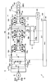
- Embodiment 1 of this invention It is a circuit diagram which shows the structure of the power supply device of the electric vehicle by Embodiment 1 of this invention.
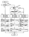
- 3 is a flowchart illustrating a control process for charging a main battery and an auxiliary battery in the power supply device for an electric vehicle according to the first embodiment.
- It is a circuit diagram which shows the structure of the power supply device of the electric vehicle by Embodiment 2 of this invention.
- 10 is a flowchart illustrating a control process for charging a main battery and an auxiliary battery in a power supply device for an electric vehicle according to a second embodiment.
- It is a circuit diagram which shows the structure of the power supply device of the electric vehicle by Embodiment 3 of this invention.
- 12 is a first flowchart illustrating a control process for charging a main battery and an auxiliary battery in a power supply device for an electric vehicle according to a third embodiment.
- 12 is a second flowchart illustrating a control process for charging a main battery and an auxiliary battery in the power supply device for an electric vehicle according to the third embodiment.
- It is a circuit diagram which shows the structure of the power supply device of the electric vehicle by the modification of Embodiment 3 of this invention. It is a flowchart explaining the control processing for charge of the main battery by this Embodiment 4, and an auxiliary machine battery.
- It is a circuit diagram which shows the 1st modification of a structure of a power conversion unit.
- It is a circuit diagram which shows the 2nd modification of a structure of a power conversion unit.
- FIG. 1 is a circuit diagram showing a configuration of a power supply device for an electric vehicle according to Embodiment 1 of the present invention.
- an electric vehicle 5 includes a main battery 10, system main relays SMR1 and SMR2, a power control unit (PCU) 20, a smoothing capacitor C0, a motor generator 30, a power transmission gear 40, Drive wheel 50, auxiliary battery 70, and control device 100 are provided.
- a power supply device for the electric vehicle 5 is configured by a portion excluding the motor generator 30, the power transmission gear 40, and the drive wheels 50 from the configuration of FIG. 1.
- the main battery 10 is shown as an example of a “main power storage device”, and typically includes a secondary battery such as a lithium ion battery or a nickel metal hydride battery.
- a secondary battery such as a lithium ion battery or a nickel metal hydride battery.
- the output voltage of the main battery 10 is about 200V.
- the “main power storage device” may be configured by an electric double layer capacitor or a combination of a secondary battery and a capacitor.
- the PCU 20 converts the stored power of the main battery 10 into power for driving and controlling the motor generator 30.
- motor generator 30 is constituted by a permanent magnet type three-phase synchronous motor
- PCU 20 is constituted by a three-phase inverter.
- the PCU 20 may be configured by a combination of a converter that variably controls the output voltage from the main battery 10 and a three-phase inverter that converts the output voltage of the converter into an AC voltage.
- System main relays SMR1 and SMR2 are connected to an energization path between main battery 10 and PCU 20.
- System main relays SMR 1, SMR 2 are turned on in response to a start command for the electric system of electric vehicle 5. Therefore, system main relays SMR1 and SMR2 are turned on so that motor generator 30 can be driven by the electric power of main battery 10 at least when electric vehicle 5 is operating.
- the positive terminal and the negative terminal of the main battery 10 are connected to the power lines 151p and 151g of the PCU 20 via the system main relays SMR1 and SMR2. Smoothing capacitor C0 is connected to power lines 151p and 151g and smoothes the DC voltage.
- the output torque of the motor generator 30 is transmitted to the drive wheels 50 via a power transmission gear 40 constituted by a speed reducer and a power split mechanism, and the electric vehicle 5 is caused to travel.
- the motor generator 30 can generate electric power by the rotational force of the drive wheels 50 during the regenerative braking operation of the electric vehicle 5.
- the generated power is converted into charging power for the main battery 10 by the PCU 20.
- the electric vehicle 5 comprehensively shows a vehicle equipped with a traveling electric motor, and includes a hybrid vehicle that generates a vehicle driving force by the engine and the electric motor, an electric vehicle not equipped with an engine, a fuel cell vehicle, and the like.
- the control device 100 includes a CPU (Central Processing Unit) (not shown) and an electronic control unit (ECU) with a built-in memory.
- the ECU is configured to perform arithmetic processing using detection values from the sensors based on the map and program stored in the memory.
- at least a part of the ECU may be configured to execute predetermined numerical / logical operation processing by hardware such as an electronic circuit.
- the auxiliary battery 70 is shown as an example of a “sub power storage device”, and is constituted by, for example, a lead storage battery.
- the voltage of auxiliary battery 70 is lower than the output voltage of main battery 10 and is, for example, about 12V. Electric power is supplied from the auxiliary battery 70 to an auxiliary load (not shown).
- Auxiliary equipment loads include air conditioning equipment, audio equipment, navigation equipment, lighting equipment (hazard lamps, room lights, headlamps, etc.) and the like.
- the auxiliary machine load includes a traveling system load that is directly used for traveling the vehicle, such as an electric power steering mechanism, an electric oil pump, and an electronically controlled small motor.
- the control device 100 and other ECUs are also operated by electric power from the auxiliary battery 70.
- the power consumption due to the auxiliary load is also simply referred to as “auxiliary power consumption”.
- the electric vehicle 5 includes a charging device 200 for externally charging the main battery 10 (main power storage device) with an external power source 400 and main charging relays CHR1 and CHR2 in addition to the above configuration.
- Electric vehicle 5 further includes sub charging relays SCR1 and SCR2.
- the sub charging relays SCR1 and SCR2 correspond to the “first switch”.
- External power supply 400 is typically composed of a commercial power supply. At the time of external charging, the external power supply 400 is electrically connected to the electric vehicle 5 by connecting the charging cable 410 to the electric vehicle 5.
- Connection relays CBR1 and CBR2 are inserted and connected to the energization path via the charging cable 410 between the power line 159 in the electric vehicle 5 and the external power supply 400. Connection relays CBR1 and CBR2 are turned on (closed) or turned off (opened) according to a control command from control device 100, for example. The connection relays CBR1 and CBR2 correspond to a “second switch”.
- connection relays CBR1 and CBR2 can be turned on when the charging cable 410 is normally connected to the electric vehicle 5.
- the external power source 400 can be electrically disconnected from the charging device 200 by turning off the connection relays CBR1 and CBR2 even when the charging cable 410 is connected.
- Connection relays CBR1 and CBR2 may be arranged inside electric vehicle 5 or may be built in charging cable 410.
- Each of the relays shown in this embodiment is typically closed (ON) by connecting the contacts when energized, and opened (OFF) by disconnecting the contacts when de-energized.
- any switch including a semiconductor relay can be applied as long as it can control closing (on) and opening (off).
- the charging device 200 includes a power conversion unit 240, a power conversion unit 250, an LC filter 270, a smoothing reactor L1, and smoothing capacitors C1 and C2.
- the power conversion unit 240 includes power semiconductor switching elements Q9 to Q12.
- an IGBT Insulated Gate Bipolar Transistor
- switching element any element that can be turned on / off, such as a power MOS (Metal Oxide Semiconductor) transistor or a power bipolar transistor, can be used as the switching element.
- Anti-parallel diodes D9 to D12 are arranged for switching elements Q9 to Q12, respectively.
- Switching elements Q9 to Q12 constitute a full bridge circuit (hereinafter also referred to as a first full bridge circuit) between power line 159 and power lines 152p, 152g. Switching elements Q9 to Q12 are turned on / off in response to a control signal CS2 from control device 100.
- the power conversion unit 250 includes switching elements Q1 to Q4 and Q5 to Q8, and an insulating transformer 260. Antiparallel diodes D1 to D8 are connected to switching elements Q1 to Q8, respectively. Switching elements Q1 to Q8 are turned on / off in response to a control signal CS1 from control device 100.
- Switching elements Q1-Q4 form a full bridge circuit (hereinafter also referred to as a second full bridge circuit) between power lines 152p, 152g and power line 154.
- Switching elements Q5 to Q8 constitute a full bridge circuit (hereinafter also referred to as a third full bridge circuit) between power line 155 and power lines 153p and 153g.
- each of the full bridge circuits of the power conversion units 240 and 250 can perform bidirectional AC / DC power conversion by on / off control of the switching elements. It is also known that the level of a DC voltage (current) or an AC voltage (current) can be controlled by duty ratio control of a switching element in on / off control.
- the insulation transformer 260 has a primary side to which the power line 154 is connected and a secondary side to which the power line 155 is connected. As is well known, the insulating transformer 260 is configured to convert the alternating voltage according to the number of turns after electrically insulating the primary side and the secondary side.
- Smoothing capacitor C2 smoothes the DC voltage of power lines 152p and 152g.
- Smoothing capacitor C1 and smoothing reactor L1 smooth the DC voltage and DC current of power lines 153p and 153g.
- the main charging relays CHR1, CHR2 are connected between the power lines 153p, 153g and the positive terminal and the negative terminal of the main battery 10.
- Main charging relays CHR1 and CHR2 are turned on / off by a control command from control device 100.
- the sub charging relays SCR1 and SCR2 are connected between predetermined nodes N1 and N2 on the energization path during external charging of the charging device 200 and the power lines 160p and 160g. Power lines 160p and 160g are electrically connected to the positive terminal and the negative terminal of auxiliary battery 70. In the configuration of FIG. 1, the predetermined nodes N1 and N2 are provided on the power lines 152p and 152g. Sub charging relays SCR 1 and SCR 2 are turned on / off by a control command from control device 100.
- the power line 159 corresponds to the “first power line”
- the power lines 152p and 152g correspond to the “second power line”.
- the power lines 153p and 153g correspond to “third power line”.
- the power conversion unit 240 corresponds to a “first power conversion unit”.
- the power conversion unit 250 corresponds to a “second power conversion unit” or a “DC / DC conversion unit”.
- the charging device 200 performs the following power conversion (first power conversion) during external charging.
- control device 100 turns on connection relays CBR1 and CBR2 and main charging relays CHR1 and CHR2. On the other hand, control device 100 turns off sub charging relays SCR1 and SCR2.
- the connection relays CBR1 and CBR2 When the connection relays CBR1 and CBR2 are turned on, the voltage V1 of the power line 159 becomes an AC voltage from the external power supply 400.
- the first full bridge circuit (Q9 to Q12) of the power conversion unit 240 converts the AC voltage (V1) on the power line 159 into a DC voltage (V2) and outputs it to the power lines 152p and 152g.
- the power conversion unit 240 controls the AC / DC conversion so as to improve the power factor of the power supplied from the external power supply 400. That is, it is preferable that the power conversion unit 240 also operates as a PFC (Power Factor Correction) circuit during external charging.
- PFC Power Factor Correction
- the voltage V2 of the power lines 152p and 152g during external charging is controlled by the power conversion unit 240 to a DC voltage higher than the AC voltage amplitude from the external power supply 400.
- the second full bridge circuit (Q1 to Q4) converts the DC voltage (V2) of the power lines 152p and 152g into a high frequency AC voltage and outputs it to the power line 154.
- the high-frequency AC voltage output to the power line 154 is transformed according to the turn ratio of the primary side and the secondary side of the insulation transformer 260 and output to the power line 155.
- the third full bridge circuit (Q5 to Q8) converts the high-frequency AC voltage output to the power line 155 into a DC voltage (V3) and outputs it to the power lines 153p and 153g.
- the DC voltage V3 of the power lines 153p and 153g is controlled to the voltage command value Vr3 by the on / off control of the switching elements Q1 to Q8 constituting the second and third full bridge circuits.
- control device 100 turns off main charging relays CHR1, CHR2 and connection relays CBR1, CBR2 when the external charging is completed.
- charging device 200 performs AC / DC conversion (first power conversion) for converting AC power from external power supply 400 into charging power (DC power) of main battery 10 during external charging.
- system main relays SMR1, SMR2 are turned off during external charging.
- the control device 100 can select auxiliary battery charging.
- the connection relays CBR1 and CBR2 are turned off, while the main charging relays CHR1 and CHR2 and the sub charging relays SCR1 and SCR2 are turned on.
- the charging device 200 operates to charge the auxiliary battery 70 by power conversion in the opposite direction to the power conversion at the time of external charging when the auxiliary battery is charged. Specifically, charging device 200 performs DC / DC conversion (second power conversion) for converting the output voltage of main battery 10 into the charging voltage of auxiliary battery 70 when the auxiliary battery is charged. Composed.
- the third full bridge circuit (Q5 to Q8) converts the DC voltage (V3) of the power lines 153p and 153g into a high frequency AC voltage and outputs it to the power line 155.
- the DC voltage V3 is an output voltage of the main battery 10.
- the high-frequency AC voltage output to power line 155 is transformed according to the turns ratio of insulating transformer 260 and output to power line 154.
- the second full bridge circuit (Q1 to Q4) converts the high-frequency AC voltage output to the power line 154 into a DC voltage (V2) and outputs the DC voltage (V2) to the power lines 152p and 152g.
- the voltage V2 of the power lines 152p and 152g is controlled to the voltage command value Vr2 by the on / off control of the switching elements Q1 to Q8 constituting the second and third full bridge circuits.
- Voltage command value Vr2 is set to a voltage level (charging voltage Vsb) suitable for charging auxiliary battery 70.
- the auxiliary battery 70 can be directly charged by the voltage (V2) output from the charging device 200 to the power lines 152p and 152g. That is, generally, the voltage (V2) of power lines 152p and 152g at the time of charging the auxiliary battery is controlled to be lower than that at the time of external charging.
- the power conversion unit 240 stops the operation when the auxiliary battery is charged. That is, switching Q9 to Q13 is fixed off.
- electric vehicle 5 further includes a DC / DC converter 280 as an additional configuration for charging auxiliary battery 70.
- DC / DC converter 280 is electrically connected between power lines 153p and 153g and the positive terminal and the negative terminal of auxiliary battery 70.
- the DC / DC converter 280 corresponds to a “power converter”.
- the DC / DC converter 280 is controlled in response to a control signal CS3 from the control device 100.
- the output voltage of DC / DC converter 280 is controlled to charge voltage Vsb of auxiliary battery 70.
- the DC / DC converter 280 is not a large-capacity one for supplying auxiliary machine power consumption, but a small-capacity one dedicated for charging the auxiliary battery 70 is applied. At least the charging power of the auxiliary battery 70 by the DC / DC converter 280 is smaller than the charging power in the auxiliary battery charging operation of the charging device 200. Therefore, the loss in the DC / DC converter 280 is also lower than that of the DC / DC converter for supplying auxiliary machine power consumption described in Patent Documents 1 to 3. When DC / DC converter 280 is arranged, auxiliary battery 70 can be charged in parallel with charging of main battery 10 during external charging.
- each step described in each flowchart demonstrated below including FIG. 2 is performed by the software process and / or hardware process by the control apparatus 100.
- FIG. Moreover, the control processing by each flowchart is performed by the control apparatus 100 for every predetermined control period.
- control device 100 determines in step S100 whether external charging is in progress.
- step S100 is determined as YES.
- step S100 is determined as YES.
- the start condition is in response to an input of a charge instruction by the user or arrival of a charge start time instructed in advance by the user in a state where the external power supply 400 is normally connected to the electric vehicle 5 by the charging cable 410. It is established. Further, the termination condition is established in response to the fact that the charge level (SOC: State of Charge) of the main battery 10 has reached the charge target value or the completion of charging for a predetermined time or a predetermined amount of power.
- SOC State of Charge
- Control device 100 executes the following steps S120, S130, S140, and S150 during external charging (when YES is determined in S100).
- control device 100 turns on main charging relays CHR1, CHR2 and connection relays CBR1, CBR2 in step S120.
- sub charging relays SCR1 and SCR2 are turned off.
- the control device 100 controls the power conversion unit 240 and the power conversion unit 250 to execute the charging operation of the main battery 10 in steps S130 and S140. Thereby, the above-described AC / DC conversion (first power conversion) is executed, and AC power from the external power source 400 is converted into charging power (DC power) of the main battery 10. Then, the main battery 10 is charged by the DC voltage (V3) output from the charging device 200 to the power lines 153p and 153g via the main charging relays CHR1 and CHR2.
- the control device 100 further operates the DC / DC converter 280 in step S150.
- DC / DC converter 280 steps down DC voltage (V3) on power lines 153p and 153g to charging voltage Vsb of auxiliary battery 70. Then, auxiliary battery 70 is charged in parallel with charging of main battery 10 by the output voltage of DC / DC converter 280.
- control device 100 determines whether or not auxiliary battery charging is necessary according to the operating state of the auxiliary machine that is operated by the electric power from auxiliary battery 70 in step S110. judge.
- step S110 includes step S112 for determining whether the electric vehicle 5 is in operation, and step S115 for determining whether the total load power of the auxiliary machine is greater than a predetermined threshold value ( ⁇ ).
- step S112 it is determined whether or not the electric vehicle 5 is in operation. For example, if the system main relays SMR1 and SMR2 are turned on, each auxiliary machine load needs to be actuated immediately in response to a user operation. For this reason, in order to ensure sufficient auxiliary machine power consumption, step S112 is set as YES determination.
- step S115 it is determined whether or not the current auxiliary machine power consumption is larger than a predetermined threshold value ( ⁇ ). Thereby, even if the electric vehicle 5 is not in operation (NO in S112), if the power consumption due to the operation of the air conditioner, lighting device, audio device, or the like is large, the determination in step S115 is YES.
- step S112 or S115 the control device 100 determines that step S110 is YES and determines that the auxiliary battery needs to be charged. On the other hand, when steps S112 and S115 are NO, control device 100 determines that step S110 is NO and determines that the auxiliary battery charging is unnecessary.
- controller 100 determines that the auxiliary battery 70 needs to be charged (YES in S110)
- control device 100 performs steps S125, S135, S145 and S155 to charge auxiliary battery 70. Execute the process.
- step S125 the control device 100 turns on the main charging relays CHR1, CHR2 and the sub charging relays SCR1, SCR2, while turning off the connection relays CBR1, CBR2.
- the control device 100 stops the operation of the DC / DC converter 280 in step S155. This is because the DC / DC converter 280 is of a small capacity dedicated to charging the auxiliary battery 70 and is therefore less effective in securing auxiliary machine power consumption. However, even when the auxiliary battery is charged at the time of non-external charging, the DC / DC converter 280 is operated to charge the auxiliary battery 70 by both the charging device 200 (power conversion unit 250) and the DC / DC converter 280. Electric power may be supplied.
- control device 100 executes the processes of steps S122, S132, S142, and S152.
- step S122 the control device 100 turns off the main charging relays CHR1, CHR2, the sub charging relays SCR1, SCR2, and the connection relays CBR1, CBR2.
- control apparatus 100 stops operation
- step S110 YES.
- charging of auxiliary battery 70 is started by the processing of steps S125, S135, S145, and S155. That is, the auxiliary machine power consumption is supplied using the power of the main battery 10 as a source.
- the power supply device for an electric vehicle As described above, according to the power supply device for an electric vehicle according to the first embodiment, at least a part of the configuration of charging device 200 for external charging is shared, and power conversion in the direction opposite to that during external charging is performed.
- the auxiliary battery 70 can be charged.
- the voltage of the nodes N1 and N2 power lines 152p and 152g in FIG. 1 to which the sub charging relays SCR1 and SCR2 are connected is controlled to a voltage level different from that during external charging.
- the charging voltage (Vsb) of the machine battery 70 can be directly output by the charging device 200.
- a power converter (a large-capacity DC / DC) that converts the output voltage of the main battery 10 into the charging voltage of the auxiliary battery 70 in order to secure the power consumption of the auxiliary load. Converter) is not necessary. Therefore, the power supply device including the main battery 10 and the auxiliary battery 70 can be downsized and the manufacturing cost can be reduced.
- the auxiliary battery 70 can be charged in parallel with the main battery 10 during external charging by additionally providing a small-capacity DC / DC converter 280 that charges the auxiliary battery 70 during external charging. it can. Thereby, the charge opportunity of the auxiliary battery 70 can be increased.
- FIG. 3 is a circuit diagram showing a configuration of a power supply device for an electric vehicle according to Embodiment 2 of the present invention.
- FIG. 3 is compared with FIG. 1, in the power supply device for the electric vehicle according to the second embodiment, nodes N1 and N2 connecting the sub charging relays SCR1 and SCR2 are different from the first embodiment. Specifically, in the power supply device for an electric vehicle according to the second embodiment, nodes N1 and N2 are provided on power line 159. Since the configuration of the other parts of the power supply device is the same as that of the first embodiment, detailed description will not be repeated.
- FIG. 4 is a flowchart illustrating a control process for charging the main battery and the auxiliary battery in the power supply device for the electric vehicle according to the second embodiment.
- control device 100 replaces steps S135 and S145 (FIG. 2) at the time of charging the auxiliary battery (at the time of YES determination at S110), Charging device 200 is controlled in steps S135 # and S145 #. Since the processes of steps S125 and S155 when the auxiliary battery is charged are the same as those in FIG. 2, the description thereof will not be repeated.
- Control device 100 controls power conversion units 240 and 250 to execute an auxiliary battery charging operation in steps S135 # and S145 #.
- power conversion unit 250 steps down the DC voltage from main battery 10 and outputs it to power lines 152p, 152g (S135 #).
- the voltage (V2) of the power lines 152p and 152g is lower than the output voltage (Vmb) of the main battery 10 and higher than the charging voltage (Vsb) of the auxiliary battery 70 (Vmb> V2> Vsb).
- power conversion unit 240 converts the voltage (V2) of power lines 152p and 152g to the charging voltage (Vsb) of auxiliary battery 70, and outputs it to power line 159 (S145 #).
- the power conversion unit 240 performs the AC / DC conversion operation from the power line 159 toward the power lines 152p and 152g during external charging, while the power line 152p and 152g switches from the power lines 152p and 152g to the power line 159 during auxiliary battery charging operation. DC / DC conversion is performed.
- DC / DC conversion for converting the DC voltage from the main battery 10 into the charging voltage of the auxiliary battery 70 is executed by the power conversion units 240 and 250.
- step S125, S135, S145, S155 Since the processing at the time of external charging (steps S125, S135, S145, S155) and the processing at the time when auxiliary battery charging is unnecessary (steps S122, S132, S142, S152) are the same as those in FIG. 2, the description will not be repeated.
- the configuration of the charging device 200 for external charging is shared, and by power conversion in the direction opposite to that during external charging, The auxiliary battery 70 can be directly charged. Therefore, the power supply device including the main battery 10 and the auxiliary battery 70 can be downsized and the manufacturing cost can be reduced.
- both of the power conversion units 240 and 250 perform DC / DC conversion (step-down), so that the controllability of the charging voltage of the auxiliary battery 70 is controlled. Will improve.
- charging device 200 alternatively performs charging of main battery 10 and charging of auxiliary battery 70. Therefore, the arrangement of the small-capacity DC / DC converter 280 has been described as a configuration for charging the auxiliary battery 70 in parallel with the main battery 10 during external charging. In the third embodiment, a variation of the circuit configuration for charging the auxiliary battery during external charging will be described.
- FIG. 5 is a circuit diagram showing a configuration of a power supply device for an electric vehicle according to Embodiment 3 of the present invention. 5 is compared with FIG. 1, an AC / DC converter 285 is provided in place of DC / DC converter 280 in the power supply device for the electric vehicle according to the third embodiment. Since the structure of other parts in FIG. 5 is the same as that of the first embodiment (FIG. 1), detailed description will not be repeated.
- the AC / DC converter 285 has a relatively small capacity like the DC / DC converter 280. That is, the AC / DC converter 285 corresponds to a “power converter” in the same manner as the DC / DC converter 280.
- AC / DC converter 285 is connected to a node capable of taking out AC power in the power conversion path of charging apparatus 200.
- the AC / DC converter 285 is connected between the coil winding 261 of the isolation transformer 260 and the auxiliary battery 70.
- the coil winding 261 can be configured by further providing a tap on the insulating transformer 260 of FIG. Alternatively, the coil winding 261 may be provided by sharing the power line 154 or 155. That is, AC / DC converter 285 may be connected between power line 154 or 155 and auxiliary battery 70.
- AC / DC converter 285 converts the high-frequency AC voltage generated in isolation transformer 260 into a charging voltage (Vsb) of auxiliary battery 70. Therefore, AC / DC converter 285 can charge auxiliary battery 70 at least during external charging, similarly to DC / DC converter 280 shown in FIG.
- FIG. 6 is a flowchart illustrating a control process for charging the main battery and the auxiliary battery in the power supply device for the electric vehicle according to the third embodiment.
- control device 100 replaces steps S150, S152, and S155 (FIG. 2) with steps S150 #, S152 #, and S155 #. Execute.
- control of each relay (steps S120, S122, S125) and control of the power conversion units 240, 250 (steps S130, S132, S135, S140, S142, S145) by the control device 100 are the same as in FIG. The explanation will not be repeated.
- control device 100 operates AC / DC converter 285 to charge auxiliary battery 70 in step S150 #.
- control device 100 stops the operation of AC / DC converter 285 in step S152 # when auxiliary battery charging is not required during non-external charging (NO determination in S110).
- Control device 100 basically stops the operation of AC / DC converter 285 in step S155 # when auxiliary battery charging is required during non-external charging (YES in S110). As described in step S155 (FIG. 2), AC / DC converter 285 may be operated and auxiliary battery 70 may be charged by both charging device 200 and AC / DC converter 285.
- auxiliary battery 70 can be charged in parallel with main battery 10 during external charging. Become.
- nodes N1 and N2 to which the sub charging relays SCR1 and SCR2 are connected can be provided on the power line 159 as in FIG. 3 (Embodiment 2).
- the control process for charging the main battery and the auxiliary battery is executed according to the flowchart shown in FIG.
- control device 100 replaces steps S135 and S145 of FIG. 6 with steps S135 # and S145 of FIG. Execute #. Since the processing of other steps is the same as in FIG. 6, description thereof will not be repeated.
- Embodiment 1 In any of the power supply devices of Embodiment 1 (FIG. 1) and Embodiment 2 (FIG. 3), instead of DC / DC converter 280, AC / DC converter 285 may be arranged.
- the auxiliary battery 70 can be charged in parallel with the main battery 10 during external charging.
- FIG. 8 is a circuit diagram showing a configuration of a power supply device for an electric vehicle according to a modification of the third embodiment.
- FIG. 8 is compared with FIG. 5, in the electric vehicle power supply device according to the modification of the third embodiment, the location of the AC / DC converter 285 is different from that of the third embodiment (FIG. 5). Specifically, AC / DC converter 285 is connected between power line 159 and auxiliary battery 70. As a result, the insulating transformer 260 need not be provided with the coil winding 261 (FIG. 5). The configuration of the other parts in FIG. 8 is the same as that in FIG.
- AC voltage from the external power source 400 is transmitted to the power line 159 during external charging. Therefore, AC / DC converter 285 converts the AC voltage on power line 159 to the charging voltage (Vsb) of auxiliary battery 70 during external charging. Thereby, auxiliary battery 70 can be charged during external charging.
- the main battery 10 and the auxiliary battery 70 can be charged by the same control process as that in the flowchart shown in FIG.
- the sub charging relays SCR1 and SCR2 can be connected between the power line 159 and the auxiliary battery 70 as in the second embodiment (FIG. 3).
- the main battery 10 and the auxiliary battery 70 can be charged by a control process similar to the flowchart shown in FIG.
- the AC / DC converter 285 can be connected to any node as long as AC power can be taken out of the power conversion path at the time of external charging in the charging device 200.
- auxiliary battery 70 cannot be charged by charging device 200 during external charging. Even if the small-capacity DC / DC converter 280 or the AC / DC converter 285 is provided, it is difficult to sufficiently supply the auxiliary machine power consumption.
- the charge amount of the auxiliary equipment battery 70 may be reduced. If the output voltage of the auxiliary battery 70 is significantly reduced, there is a possibility that the start of the vehicle travel may be hindered due to the ECU not being able to start.
- FIG. 9 is a flowchart illustrating a control process for charging the main battery and the auxiliary battery in the power supply device for the electric vehicle according to the fourth embodiment.
- control device 100 executes the following steps S200 to S220 instead of steps S120 to S150 (FIG. 2 and the like) during external charging (when YES is determined in S100).
- control processing at the time of non-external charging is similar to the flowchart of FIG.
- step S200 the control device 100 determines whether or not the auxiliary machine power consumption during external charging is greater than a predetermined threshold value ( ⁇ ).
- control device 100 When the auxiliary machine power consumption is small (NO in S200), control device 100 performs normal external charging in steps S120, S130, S140, and S150 (S150 #) in step S210. . That is, the AC voltage from the external power supply 400 is converted into the charging voltage (Vmb) of the main battery 10 by AC / DC conversion by the charging device 200. Furthermore, preferably, auxiliary battery 70 is charged by small capacity DC / DC converter 280 or AC / DC converter 285.
- step S220 the control device 100 performs (i) a normal external charging period similar to that in step S210, and (ii) a supplement in which external charging is stopped in steps S125, S130, S145 (S145 #), and S155 described above.
- the charging device 200 is controlled to alternately provide the battery charging period.
- charging apparatus 200 is not limited to the configurations shown in Embodiments 1 to 3 and the modifications thereof, and is required for each of the above-described external charging and auxiliary battery charging. If it is possible to perform power conversion, an arbitrary circuit configuration can be applied for confirmation.
- FIG. 10 shows a modification of the power conversion unit 250.
- power conversion unit 250 # according to the modification has a configuration of a non-insulated chopper circuit instead of the insulated full bridge circuit shown in FIG. Specifically, power conversion unit 250 # includes switching elements Q20, Q21 and reactor L1. Switching element Q20 is electrically connected between power line 152p and power line 153p. Switching element Q21 is electrically connected between switching element Q20 and power line 153g. Antiparallel diodes D20 and D21 are connected to switching elements Q20 and Q21. The power lines 152g and 153g are not insulated and become common wiring.
- power conversion unit 250 # forms a current bidirectional chopper circuit using smoothing reactor L1 connected to power line 153p.
- Power conversion unit 250 # can perform bidirectional DC / DC conversion between DC voltage (V3) of power lines 153p and 153g and DC voltage (V2) of power lines 152p and 152g. It is known that the voltage ratio (V3 / V2) in DC / DC conversion can be controlled by the duty ratio when the switching elements Q20 and Q21 are complementarily turned on and off within a predetermined switching period.
- power conversion unit 250 # can also handle both DC / DC conversion during external charging and DC / DC conversion during auxiliary battery charging by the duty control.
- power conversion unit 250 # can be used in place of power conversion unit 250 in the first to fourth embodiments.
- FIG. 11 shows a modification of the power conversion unit 240.
- a power conversion unit 240 # according to the modification includes a diode bridge 241 and a chopper circuit 242 instead of the full bridge circuit shown in FIG.
- the diode bridge 241 includes diodes D24 to D27.
- the diode bridge 241 performs full-wave rectification on the AC voltage of the power line 159 and outputs it to the power lines 158p and 158g.
- the chopper circuit 242 has switching elements Q22 and Q23 connected in series between the power lines 152p and 152g, and a reactor L2. Antiparallel diodes D22 and D23 are connected to switching elements Q22 and Q23. Since the configuration and operation of chopper circuit 242 are similar to those of power conversion unit 250 # shown in FIG. 10, description thereof will not be repeated. That is, the chopper circuit 242 performs bidirectional DC voltage conversion between the power lines 152p and 152g and the power lines 158p and 158g.
- Power conversion unit 240 # rectifies the AC voltage from external power supply 400 supplied to power line 159 by diode bridge 241, and further converts the DC voltage by chopper circuit 262, whereby DC voltage (V2 of power lines 152p and 152g). ) Can be controlled. Therefore, similarly to power conversion unit 240, power conversion unit 240 # can perform AC / DC conversion necessary for external charging.
- power conversion unit 240 # can step down DC voltage (V2) of power lines 152p and 152g to the charging voltage (Vsb) of auxiliary battery 70 and output it to power lines 158p and 158g. Therefore, similarly to power conversion unit 240, power conversion unit 240 # can perform DC / DC conversion necessary for charging the auxiliary battery in the configuration of the second embodiment (FIG. 3).
- nodes N1 and N2 need to be provided not on power line 159 but on power lines 158p and 158g. Thereby, auxiliary battery 70 is charged by the DC voltage of power lines 158p and 158g by turning on sub charging relays SCR1 and SCR2.
- power conversion unit 240 # can be used in place of power conversion unit 240 in the first to fourth embodiments.
- the configuration of the power lines 151p, 151g and the following is not limited to the illustrated configuration. That is, as described above, the present invention can be commonly applied to an electric vehicle equipped with a traveling electric motor such as an electric vehicle, a hybrid vehicle, and a fuel cell vehicle.
- the present invention can be applied to an electric vehicle configured to be able to charge an in-vehicle power storage device with an external power source.
Landscapes
- Engineering & Computer Science (AREA)
- Power Engineering (AREA)
- Transportation (AREA)
- Mechanical Engineering (AREA)
- Life Sciences & Earth Sciences (AREA)
- Sustainable Development (AREA)
- Sustainable Energy (AREA)
- Charge And Discharge Circuits For Batteries Or The Like (AREA)
- Electric Propulsion And Braking For Vehicles (AREA)
Abstract
Description
図1は、本発明の実施の形態1による電動車両の電源装置の構成を示す回路図である。
電力変換ユニット240,250の各フルブリッジ回路は、周知のように、スイッチング素子のオンオフ制御によって、双方向のAC/DC電力変換を実行することができる。また、オンオフ制御におけるスイッチング素子のデューティ比制御によって、直流電圧(電流)あるいは交流電圧(電流)のレベルについても制御可能であることが知られている。
図3は、本発明の実施の形態2による電動車両の電源装置の構成を示す回路図である。
実施の形態1および2で説明したように、充電装置200は、メインバッテリ10の充電と、補機バッテリ70の充電とを択一的に実行する。このため、外部充電時に、メインバッテリ10と並列に補機バッテリ70を充電するための構成として、小容量のDC/DCコンバータ280の配置を説明した。実施の形態3では、外部充電時の補機バッテリ充電のための回路構成のバリエーションを説明する。
図5を図1と比較して、実施の形態3による電動車両の電源装置では、DC/DCコンバータ280に代えて、AC/DCコンバータ285が配設される。図5のその他の部分の構成は、実施の形態1(図1)と同様であるので詳細な説明は繰返さない。AC/DCコンバータ285は、DC/DCコンバータ280と同様に、比較的小容量のものが適用される。すなわち、AC/DCコンバータ285は、DC/DCコンバータ280と同様に、「電力変換器」に対応する。
図8は実施の形態3の変形例による電動車両の電源装置の構成を示す回路図である。
実施の形態1~3およびその変形例に示した電動車両の電源装置では、外部充電時には、充電装置200によって補機バッテリ70を充電することができない。仮に、小容量のDC/DCコンバータ280またはAC/DCコンバータ285を設けても、補機消費電力を十分に供給することは困難である。
図10を参照して、変形例による電力変換ユニット250♯は、図1等に示された絶縁型フルブリッジ回路に代えて、非絶縁型チョッパ回路の構成を有する。具体的には、電力変換ユニット250♯は、スイッチング素子Q20,Q21およびリアクトルL1を含む。スイッチング素子Q20は、電力線152pおよび電力線153pの間に電気的に接続される。スイッチング素子Q21は、スイッチング素子Q20および電力線153gの間に電気的に接続される。スイッチング素子Q20,Q21には、逆並列ダイオードD20,D21が接続される。電力線152gおよび153gは、絶縁されず共通の配線となる。
図11を参照して、変形例による電力変換ユニット240♯は、図1等に示されたフルブリッジ回路に代えて、ダイオードブリッジ241およびチョッパ回路242を含む。
Claims (15)
- 主蓄電装置(10)と、
前記主蓄電装置よりも出力電圧が低い副蓄電装置(70)と、
外部充電時に、外部電源(400)からの電力を前記主蓄電装置の充電電力に変換する第1の電力変換を実行するための充電装置(200)と、
前記充電装置の前記第1の電力変換における通電経路上の所定ノード(N1,N2)と前記副蓄電装置との間に接続された、前記外部充電時に開放される第1の開閉器(SCR1,SCR2)とを備え、
前記充電装置は、非外部充電時における前記第1の開閉器の閉成時に、前記通電経路の少なくとも一部を用いて前記主蓄電装置の電力を前記副蓄電装置の充電電力に変換して前記所定ノードに出力する第2の電力変換を実行するように構成される、電動車両の電源装置。 - 非外部充電時において、前記第1の開閉器(SCR1,SCR2)の閉成および前記充電装置(200)による前記第2の電力変換は、前記副蓄電装置(70)からの電力によって動作する補機の動作状態に応じて実行される、請求項1記載の電動車両の電源装置。
- 前記外部充電時において、前記第1の電力変換の経路上の電力を前記副蓄電装置の充電電力に変換するための電力変換器(280,285)をさらに備え、
前記電力変換器による前記副蓄電装置の充電電力は、前記充電装置の前記第2の電力変換による前記副蓄電装置の充電電力よりも小さい、請求項1記載の電動車両の電源装置。 - 前記電力変換器(280)は、前記主蓄電装置と電気的に接続されたノードと、前記副蓄電装置(70)との間に接続される、請求項3記載の電動車両の電源装置。
- 前記電力変換器(285)は、前記外部電源(400)と電気的に接続されたノードと、前記副蓄電装置(70)との間に接続される、請求項3記載の電動車両の電源装置。
- 前記充電装置(200)は、
絶縁トランス(260)を含んで構成されたDC/DC変換ユニット(250)を含み、
前記電力変換器(285)は、前記絶縁トランスのコアに巻回されたコイル巻線(261)と前記副蓄電装置(70)との間に接続される、請求項3記載の電動車両の電源装置。 - 前記充電装置(200)は、
前記外部電源(400)と接続された第1の電力線(159)から第2の電力線(152p,152g)へ向けて交流/直流電圧変換を実行するための第1の電力変換ユニット(240)と、
前記主蓄電装置(10)と接続された第3の電力線(153p,153g)と前記第2の電力線との間で双方向の直流/直流電圧変換を実行するための第2の電力変換ユニット(250)とを含み、
前記所定ノード(N1,N2)は、前記第2の電力線に設けられ、
前記第1の電力変換において、前記第1の電力変換ユニットは、前記第1の電力線上の交流電圧を直流電圧に変換して前記第2の電力線に出力し、かつ、前記第2の電力変換ユニットは、前記第2の電力線の直流電圧を前記主蓄電装置の充電電圧に変換して前記第3の電力線へ出力し、
前記第2の電力変換において、前記第1の電力変換ユニットは、動作を停止し、かつ、前記第2の電力変換ユニットは、前記第3の電力線に出力された前記主蓄電装置からの電圧を、前記副蓄電装置(70)の充電電圧に降圧して前記第2の電力線に出力する、請求項1~3のいずれか1項に記載の電動車両の電源装置。 - 前記充電装置(200)は、
前記第1の電力変換において、前記外部電源と接続された第1の電力線(159)から第2の電力線(152p,152g)へ向けて交流/直流電圧変換を実行する一方で、前記第2の電力変換において、前記第2の電力線から前記第1の電力線へ向けて直流/直流電圧変換を実行するための第1の電力変換ユニット(240)と、
前記主蓄電装置(10)と接続された第3の電力線(153p,153g)と前記第2の電力線との間で双方向の直流/直流電圧変換を実行するための第2の電力変換ユニット(250)とを含み、
前記第1の電力変換において、前記第1の電力変換ユニットは、前記第1の電力線上の交流電圧を直流電圧に変換して前記第2の電力線に出力し、かつ、前記第2の電力変換ユニットは、前記第2の電力線の直流電圧を前記主蓄電装置の充電電圧に変換して、前記第3の電力線へ出力し、
前記第2の電力変換において、前記第2の電力変換ユニットは、前記第3の電力線に伝達された前記主蓄電装置の出力電圧を降圧して前記第2の電力線に出力し、かつ、第1の電力変換ユニットは、前記第2の電力線の直流電圧を前記副蓄電装置(70)の充電電圧に降圧し、
前記所定ノード(N1,N2)は、前記第1の電力変換ユニットが前記副蓄電装置の充電電圧を出力する電力線(158p,158g/159)に設けられる、請求項1~3のいずれか1項に記載の電動車両の電源装置。 - 前記充電装置(200)は、前記外部充電時に、前記副蓄電装置(70)からの電力によって動作する補機の消費電力が所定値以上であるときには、前記第1の電力変換を実行する期間と、前記第2の電力変換を実行する期間とを交互に設けるように動作し、
前記充電装置が前記第1の電力変換を実行する期間では、前記第1の開閉器(SCR1,SCR2)が開放される一方で、前記外部電源(400)と前記充電装置との間に接続された第2の開閉器(CBR1,CBR2)は閉成され、
前記充電装置が前記第2の電力変換を実行する期間では、前記第1の開閉器が閉成される一方で、前記第2の開閉器は開放される、請求項1または2に記載の電動車両の電源装置。 - 主蓄電装置(10)と、前記主蓄電装置よりも出力電圧が低い副蓄電装置(70)とを備えた電動車両の電源装置の制御方法であって、
外部電源(400)によって前記主蓄電装置を充電する外部充電時に、前記外部電源からの電力を前記主蓄電装置の充電電力に変換するための第1の電力変換を充電装置(200)に実行させるステップ(S130,S140)と、
前記外部充電時に、前記充電装置の前記第1の電力変換における通電経路上の所定ノード(N1,N2)と前記副蓄電装置との間に接続された第1の開閉器(SCR1,SCR2)を開放するステップ(S120)と、
前記第1の電力変換の非実行時に、前記第1の開閉器を閉成するステップ(S125)と、
前記第1の開閉器が閉成されたときに、前記通電経路の少なくとも一部を用いて前記主蓄電装置の電力を前記副蓄電装置の充電電力に変換して前記所定ノードに出力する第2の電力変換を前記充電装置に実行させるステップ(S135,S145)とを備える、電動車両の電源装置の制御方法。 - 非外部充電時において、前記副蓄電装置(70)からの電力によって動作する補機の動作状態に応じて、前記副蓄電装置の充電要否を判定するステップ(S110)と、
前記副蓄電装置の充電が不要と判定されたときに、前記充電装置の動作を停止させるステップ(S132,S142)とをさらに備え、
前記閉成するステップ(S125)は、前記非外部充電時に前記副蓄電装置の充電が必要と判定されたときに前記第1の開閉器を閉成する、請求項10記載の電動車両の電源装置の制御方法。 - 前記外部充電時において、前記第1の電力変換の経路上の電力を前記副蓄電装置の充電電力に変換するための電力変換器(280,285)を動作させるステップ(S150,S150♯)をさらに備え、
前記電力変換器による前記副蓄電装置の充電電力は、前記充電装置の前記第2の電力変換による前記副蓄電装置の充電電力よりも小さい、請求項10または11に記載の電動車両の電源装置の制御方法。 - 前記外部充電時に、前記副蓄電装置(70)からの電力によって動作する補機の消費電力が所定値より大きいか否かを判定するステップ(S200)と、
前記消費電力が前記所定値より大きいときに、前記第1の電力変換を実行する期間と、前記第2の電力変換を実行する期間とを交互に設けるように前記充電装置(200)を制御するステップ(S220)とをさらに備え、
前記充電装置が前記第1の電力変換を実行する期間では、前記第1の開閉器(SCR1,SCR2)が開放される一方で、前記外部電源(400)と前記充電装置との間に接続された第2の開閉器(CBR1,CBR2)は閉成され、
前記充電装置が前記第2の電力変換を実行する期間では、前記第1の開閉器が閉成される一方で、前記第2の開閉器は開放される、請求項10または11に記載の電動車両の電源装置の制御方法。 - 前記充電装置(200)は、
前記外部電源(400)と接続された第1の電力線(159)から第2の電力線(152p,152g)へ向けて交流/直流電圧変換を実行するための第1の電力変換ユニット(240)と、
前記主蓄電装置(10)と接続された第3の電力線(153p,153g)と前記第2の電力線との間で双方向の直流/直流電圧変換を実行するための第2の電力変換ユニット(250)とを含み、
前記所定ノード(N1,N2)は、前記第2の電力線に設けられ、
前記第1の電力変換を充電装置に実行させるステップは、
前記第1の電力線上の交流電圧を直流電圧に変換して前記第2の電力線に出力するように前記第1の電力変換ユニットを制御するステップ(S140)と、
前記第2の電力線の直流電圧を前記主蓄電装置の充電電圧に変換して、前記第3の電力線へ出力するように前記第2の電力変換ユニットを制御するステップ(S130)とを含み、
前記第2の電力変換を前記充電装置に実行させるステップは、
前記第3の電力線に出力された前記主蓄電装置からの電圧を、前記副蓄電装置(70)の充電電圧に降圧して前記第2の電力線に出力するように、前記第2の電力変換ユニットを制御するステップ(S135)と、
前記第1の電力変換ユニットの動作を停止させるステップ(S145)とを含む、請求項10または11に記載の電動車両の電源装置の制御方法。 - 前記充電装置(200)は、
前記第1の電力変換において、前記外部電源と接続された第1の電力線(159)から第2の電力線(152p,152g)へ向けて交流/直流電圧変換を実行する一方で、前記第2の電力変換において、前記第2の電力線から前記第1の電力線へ直流/直流電圧変換を実行するための第1の電力変換ユニット(240)と、
前記主蓄電装置(10)と接続された第3の電力線(153p,153g)と前記第2の電力線との間で双方向の直流/直流電圧変換を実行するための第2の電力変換ユニット(250)とを含み、
前記第1の電力変換を充電装置に実行させるステップは、
前記第1の電力線上の交流電圧を直流電圧に変換して前記第2の電力線に出力するように前記第1の電力変換ユニットを制御するステップ(S140)と、
前記第2の電力線の直流電圧を前記主蓄電装置の充電電圧に変換して、前記第3の電力線へ出力するように前記第2の電力変換ユニットを制御するステップ(S130)とを含み、
前記第2の電力変換を充電装置に実行させるステップは、
前記第3の電力線に出力された前記主蓄電装置からの電圧を降圧して前記第2の電力線に出力するように前記第2の電力変換ユニットを制御するステップ(S135♯)と
前記第2の電力線の直流電圧を、前記副蓄電装置の充電電圧に降圧するように前記第1の電力変換ユニットを制御するステップ(S145♯)とを含み、
前記所定ノード(N1,N2)は、前記第1の電力変換ユニットが前記副蓄電装置の充電電圧を出力する電力線(158p,158g/159)に設けられる、請求項10または11に記載の電動車両の電源装置の制御方法。
Priority Applications (5)
| Application Number | Priority Date | Filing Date | Title |
|---|---|---|---|
| PCT/JP2010/072650 WO2012081103A1 (ja) | 2010-12-16 | 2010-12-16 | 電動車両の電源装置およびその制御方法 |
| US13/992,280 US8963482B2 (en) | 2010-12-16 | 2010-12-16 | Power supply apparatus for electrically powered vehicle and method for controlling the same |
| CN201080070695.0A CN103260931B (zh) | 2010-12-16 | 2010-12-16 | 电动车辆的电源装置及其控制方法 |
| JP2012548582A JP5534032B2 (ja) | 2010-12-16 | 2010-12-16 | 電動車両の電源装置およびその制御方法 |
| EP10860728.4A EP2653336B1 (en) | 2010-12-16 | 2010-12-16 | Power supply device for electric vehicle and control method for same |
Applications Claiming Priority (1)
| Application Number | Priority Date | Filing Date | Title |
|---|---|---|---|
| PCT/JP2010/072650 WO2012081103A1 (ja) | 2010-12-16 | 2010-12-16 | 電動車両の電源装置およびその制御方法 |
Publications (1)
| Publication Number | Publication Date |
|---|---|
| WO2012081103A1 true WO2012081103A1 (ja) | 2012-06-21 |
Family
ID=46244230
Family Applications (1)
| Application Number | Title | Priority Date | Filing Date |
|---|---|---|---|
| PCT/JP2010/072650 Ceased WO2012081103A1 (ja) | 2010-12-16 | 2010-12-16 | 電動車両の電源装置およびその制御方法 |
Country Status (5)
| Country | Link |
|---|---|
| US (1) | US8963482B2 (ja) |
| EP (1) | EP2653336B1 (ja) |
| JP (1) | JP5534032B2 (ja) |
| CN (1) | CN103260931B (ja) |
| WO (1) | WO2012081103A1 (ja) |
Cited By (5)
| Publication number | Priority date | Publication date | Assignee | Title |
|---|---|---|---|---|
| FR3001843A1 (fr) * | 2013-02-04 | 2014-08-08 | Renault Sa | Dispositif et procede correspondant de gestion de batteries de vehicule automobile, en particulier une batterie basse tension et une batterie haute tension |
| WO2015019144A3 (en) * | 2013-08-09 | 2015-06-25 | Toyota Jidosha Kabushiki Kaisha | Vehicle and method for controlling the vehicle |
| US9834101B2 (en) | 2012-06-28 | 2017-12-05 | Mitsubishi Jidosha Kogyo Kabushiki Kaisha | Charge control device for electrically driven vehicle |
| JP2020043729A (ja) * | 2018-09-13 | 2020-03-19 | 矢崎総業株式会社 | 車両電源装置 |
| JP2020529823A (ja) * | 2017-08-07 | 2020-10-08 | ヴィテスコ テクノロジーズ ゲー・エム・ベー・ハーVitesco Technologies GmbH | 自動車用の蓄電池充電装置、自動車側蓄電池充電装置を動作させるための方法、高電圧搭載電源網および蓄電池充電装置の使用 |
Families Citing this family (33)
| Publication number | Priority date | Publication date | Assignee | Title |
|---|---|---|---|---|
| US8725330B2 (en) | 2010-06-02 | 2014-05-13 | Bryan Marc Failing | Increasing vehicle security |
| CN103492222B (zh) * | 2011-04-22 | 2016-01-20 | 三菱电机株式会社 | 充电装置 |
| JP5831261B2 (ja) * | 2012-02-01 | 2015-12-09 | 株式会社デンソー | 電力伝送装置 |
| JP2014212653A (ja) * | 2013-04-19 | 2014-11-13 | パナソニック株式会社 | 接続監視装置、電池利用システム |
| DE102013225493A1 (de) * | 2013-08-12 | 2015-02-12 | Hyundai Motor Company | Umwandlervorrichtung und -verfahren eines Elektrofahrzeugs |
| JP6233173B2 (ja) * | 2014-04-25 | 2017-11-22 | トヨタ自動車株式会社 | 車両及び車両の制御方法 |
| CN203984052U (zh) * | 2014-07-28 | 2014-12-03 | 微宏动力系统(湖州)有限公司 | 混合电源 |
| US9809119B2 (en) * | 2015-01-13 | 2017-11-07 | General Electric Company | Bi-directional DC-DC power converter for a vehicle system |
| CN104638740B (zh) * | 2015-02-28 | 2017-02-22 | 重庆长安汽车股份有限公司 | 电动汽车充电装置 |
| JP6288134B2 (ja) * | 2016-03-22 | 2018-03-07 | トヨタ自動車株式会社 | 自動車 |
| DE102016205360A1 (de) * | 2016-03-31 | 2017-10-05 | Siemens Aktiengesellschaft | Vorrichtung und Verfahren zur Regelung eines Ladevorgangs einer Batterie |
| CN107662498A (zh) * | 2016-07-28 | 2018-02-06 | 比亚迪股份有限公司 | 电动汽车、电动汽车的多功能车载充电器及其控制方法 |
| US10286799B2 (en) * | 2016-08-23 | 2019-05-14 | GM Global Technology Operations LLC | Hands-free conductive battery charger for an electric vehicle |
| JP6277247B1 (ja) * | 2016-10-03 | 2018-02-07 | 本田技研工業株式会社 | 変換装置、機器及び制御方法 |
| KR101866063B1 (ko) * | 2016-10-07 | 2018-06-08 | 현대자동차주식회사 | 보조배터리의 릴레이 제어 시스템 및 그 방법 |
| WO2018073961A1 (ja) * | 2016-10-21 | 2018-04-26 | 日産自動車株式会社 | 電源システム及びその制御方法 |
| CN108092371B (zh) * | 2016-11-15 | 2020-04-03 | 华为技术有限公司 | 充放电装置 |
| JP6496356B2 (ja) * | 2017-05-30 | 2019-04-03 | 本田技研工業株式会社 | 車両 |
| JP6380637B1 (ja) * | 2017-09-21 | 2018-08-29 | オムロン株式会社 | 絶縁型双方向dc/dc変換装置及び絶縁型双方向dc/dc変換回路の制御方法 |
| US11108225B2 (en) | 2017-11-08 | 2021-08-31 | Eaton Intelligent Power Limited | System, method, and apparatus for power distribution in an electric mobile application using a combined breaker and relay |
| EP3707795A2 (en) | 2017-11-08 | 2020-09-16 | Eaton Intelligent Power Limited | Power distribution unit and fuse management for an electric mobile application |
| US11070049B2 (en) | 2017-11-08 | 2021-07-20 | Eaton Intelligent Power Limited | System, method, and apparatus for power distribution in an electric mobile application using a combined breaker and relay |
| DE102018203263A1 (de) * | 2018-03-06 | 2019-09-12 | Audi Ag | Ladeeinrichtung für ein Kraftfahrzeug |
| CN112004712A (zh) * | 2018-04-20 | 2020-11-27 | 西门子股份公司 | 充电基础设施单元和具有充电功率选项的充电基础设施 |
| US11682895B2 (en) | 2019-02-22 | 2023-06-20 | Eaton Intelligent Power Limited | Inverter assembly with integrated coolant coupling port |
| WO2021009217A2 (en) * | 2019-07-15 | 2021-01-21 | Eaton Intelligent Power Limited | Power distribution and circuit protection for a mobile application having a high efficiency inverter |
| DE102019219456A1 (de) * | 2019-12-12 | 2021-06-17 | Vitesco Technologies GmbH | Leistungsladeschaltung, Fahrzeugbordnetz und Verfahren zum Betreiben einer Leistungsladeschaltung |
| WO2021199118A1 (ja) * | 2020-03-30 | 2021-10-07 | 三菱電機株式会社 | エレベーター |
| CN114312372B (zh) * | 2020-09-30 | 2023-07-11 | 比亚迪股份有限公司 | 充电控制系统、方法、存储介质及车辆 |
| JP7517210B2 (ja) * | 2021-03-15 | 2024-07-17 | トヨタ自動車株式会社 | 電動車両 |
| EE202100018A (et) * | 2021-06-30 | 2023-02-15 | Tallinna Tehnikaülikool | Jõuelektroonikaseade sisendina kasutatava vahelduvvoolu muundamiseks alalisvooluks |
| KR20230020165A (ko) * | 2021-08-03 | 2023-02-10 | 현대자동차주식회사 | 이동식 전기차 충전 시스템 |
| WO2024065226A1 (zh) * | 2022-09-27 | 2024-04-04 | 宁德时代(上海)智能科技有限公司 | 电力设备、供电系统及车辆 |
Citations (7)
| Publication number | Priority date | Publication date | Assignee | Title |
|---|---|---|---|---|
| JPH08154311A (ja) * | 1994-11-29 | 1996-06-11 | Nippondenso Co Ltd | 電気自動車用充電装置 |
| JPH099417A (ja) | 1995-06-14 | 1997-01-10 | Toyota Autom Loom Works Ltd | 電気自動車用充電器 |
| JPH0965509A (ja) | 1995-06-14 | 1997-03-07 | Toyota Autom Loom Works Ltd | 電気自動車用電池の充電方法及び電気自動車用充電器 |
| JP2009225587A (ja) | 2008-03-17 | 2009-10-01 | Toyota Motor Corp | 電動車両 |
| JP2010004732A (ja) * | 2008-05-21 | 2010-01-07 | Honda Motor Co Ltd | 電源システム |
| JP2010272412A (ja) * | 2009-05-22 | 2010-12-02 | Toyota Motor Corp | ケーブル収納装置およびそれを備える車両 |
| JP2010279159A (ja) * | 2009-05-28 | 2010-12-09 | Toyota Motor Corp | 電動車両の電源システム |
Family Cites Families (6)
| Publication number | Priority date | Publication date | Assignee | Title |
|---|---|---|---|---|
| JPH0888907A (ja) * | 1994-09-14 | 1996-04-02 | Hitachi Ltd | 電気車用バッテリ充電装置 |
| JPH0898324A (ja) * | 1994-09-20 | 1996-04-12 | Nissan Motor Co Ltd | 電気車用充電制御装置 |
| JP3632776B2 (ja) * | 1994-10-03 | 2005-03-23 | 本田技研工業株式会社 | 電動車両用充電装置 |
| JP4290346B2 (ja) * | 2001-02-01 | 2009-07-01 | 本田技研工業株式会社 | 自動車用充電システム |
| JP4305553B2 (ja) * | 2007-10-23 | 2009-07-29 | トヨタ自動車株式会社 | 電動車両 |
| CN101499673B (zh) | 2009-02-27 | 2011-07-27 | 天津清源电动车辆有限责任公司 | 一种用于电动汽车的具有补偿充电的多功能一体化充电机 |
-
2010
- 2010-12-16 JP JP2012548582A patent/JP5534032B2/ja not_active Expired - Fee Related
- 2010-12-16 CN CN201080070695.0A patent/CN103260931B/zh not_active Expired - Fee Related
- 2010-12-16 US US13/992,280 patent/US8963482B2/en not_active Expired - Fee Related
- 2010-12-16 EP EP10860728.4A patent/EP2653336B1/en not_active Not-in-force
- 2010-12-16 WO PCT/JP2010/072650 patent/WO2012081103A1/ja not_active Ceased
Patent Citations (7)
| Publication number | Priority date | Publication date | Assignee | Title |
|---|---|---|---|---|
| JPH08154311A (ja) * | 1994-11-29 | 1996-06-11 | Nippondenso Co Ltd | 電気自動車用充電装置 |
| JPH099417A (ja) | 1995-06-14 | 1997-01-10 | Toyota Autom Loom Works Ltd | 電気自動車用充電器 |
| JPH0965509A (ja) | 1995-06-14 | 1997-03-07 | Toyota Autom Loom Works Ltd | 電気自動車用電池の充電方法及び電気自動車用充電器 |
| JP2009225587A (ja) | 2008-03-17 | 2009-10-01 | Toyota Motor Corp | 電動車両 |
| JP2010004732A (ja) * | 2008-05-21 | 2010-01-07 | Honda Motor Co Ltd | 電源システム |
| JP2010272412A (ja) * | 2009-05-22 | 2010-12-02 | Toyota Motor Corp | ケーブル収納装置およびそれを備える車両 |
| JP2010279159A (ja) * | 2009-05-28 | 2010-12-09 | Toyota Motor Corp | 電動車両の電源システム |
Non-Patent Citations (1)
| Title |
|---|
| See also references of EP2653336A4 |
Cited By (8)
| Publication number | Priority date | Publication date | Assignee | Title |
|---|---|---|---|---|
| US9834101B2 (en) | 2012-06-28 | 2017-12-05 | Mitsubishi Jidosha Kogyo Kabushiki Kaisha | Charge control device for electrically driven vehicle |
| EP2868517B1 (en) * | 2012-06-28 | 2018-07-18 | Mitsubishi Jidosha Kogyo Kabushiki Kaisha | Charge control device for electric vehicle |
| FR3001843A1 (fr) * | 2013-02-04 | 2014-08-08 | Renault Sa | Dispositif et procede correspondant de gestion de batteries de vehicule automobile, en particulier une batterie basse tension et une batterie haute tension |
| WO2015019144A3 (en) * | 2013-08-09 | 2015-06-25 | Toyota Jidosha Kabushiki Kaisha | Vehicle and method for controlling the vehicle |
| JP2020529823A (ja) * | 2017-08-07 | 2020-10-08 | ヴィテスコ テクノロジーズ ゲー・エム・ベー・ハーVitesco Technologies GmbH | 自動車用の蓄電池充電装置、自動車側蓄電池充電装置を動作させるための方法、高電圧搭載電源網および蓄電池充電装置の使用 |
| JP7078709B2 (ja) | 2017-08-07 | 2022-05-31 | ヴィテスコ テクノロジーズ ゲー・エム・ベー・ハー | 自動車用の蓄電池充電装置、自動車側蓄電池充電装置を動作させるための方法、高電圧搭載電源網および蓄電池充電装置の使用 |
| JP2020043729A (ja) * | 2018-09-13 | 2020-03-19 | 矢崎総業株式会社 | 車両電源装置 |
| US10855193B2 (en) | 2018-09-13 | 2020-12-01 | Yazaki Corporation | Vehicle power supply device |
Also Published As
| Publication number | Publication date |
|---|---|
| JP5534032B2 (ja) | 2014-06-25 |
| CN103260931B (zh) | 2015-09-09 |
| EP2653336B1 (en) | 2017-10-11 |
| CN103260931A (zh) | 2013-08-21 |
| US20130257375A1 (en) | 2013-10-03 |
| JPWO2012081103A1 (ja) | 2014-05-22 |
| EP2653336A4 (en) | 2015-03-11 |
| US8963482B2 (en) | 2015-02-24 |
| EP2653336A1 (en) | 2013-10-23 |
Similar Documents
| Publication | Publication Date | Title |
|---|---|---|
| JP5534032B2 (ja) | 電動車両の電源装置およびその制御方法 | |
| JP5348334B2 (ja) | 電動車両の電源装置およびその制御方法 | |
| JP4957873B2 (ja) | 電動車両の電源システムおよびその制御方法 | |
| CN102892615B (zh) | 电动车辆及其充电控制方法 | |
| JP5610066B2 (ja) | 電動車両の電源装置およびその制御方法 | |
| JP4993036B2 (ja) | 電動車両の電源システム | |
| CN101803147B (zh) | 蓄电装置的充电控制装置以及充电控制方法 | |
| JP4315232B1 (ja) | 電動車両 | |
| JP5071519B2 (ja) | 電力変換装置およびそれを搭載する車両 | |
| JP2012175819A (ja) | 車両の電源システム | |
| WO2013046315A1 (ja) | 電動車両の電源システム | |
| JP2010016954A (ja) | 駆動装置および車両並びに蓄電装置の充電方法 | |
| JP6333161B2 (ja) | 電動車両 | |
| JP2022128691A (ja) | 車載用変換装置 |
Legal Events
| Date | Code | Title | Description |
|---|---|---|---|
| 121 | Ep: the epo has been informed by wipo that ep was designated in this application |
Ref document number: 10860728 Country of ref document: EP Kind code of ref document: A1 |
|
| ENP | Entry into the national phase |
Ref document number: 2012548582 Country of ref document: JP Kind code of ref document: A |
|
| WWE | Wipo information: entry into national phase |
Ref document number: 13992280 Country of ref document: US |
|
| NENP | Non-entry into the national phase |
Ref country code: DE |
|
| REEP | Request for entry into the european phase |
Ref document number: 2010860728 Country of ref document: EP |
|
| WWE | Wipo information: entry into national phase |
Ref document number: 2010860728 Country of ref document: EP |