WO2012081147A1 - スパークプラグ - Google Patents
スパークプラグ Download PDFInfo
- Publication number
- WO2012081147A1 WO2012081147A1 PCT/JP2011/004985 JP2011004985W WO2012081147A1 WO 2012081147 A1 WO2012081147 A1 WO 2012081147A1 JP 2011004985 W JP2011004985 W JP 2011004985W WO 2012081147 A1 WO2012081147 A1 WO 2012081147A1
- Authority
- WO
- WIPO (PCT)
- Prior art keywords
- resistance value
- resistor
- spark plug
- center electrode
- center
- Prior art date
- Legal status (The legal status is an assumption and is not a legal conclusion. Google has not performed a legal analysis and makes no representation as to the accuracy of the status listed.)
- Ceased
Links
Images


Classifications
-
- H—ELECTRICITY
- H01—ELECTRIC ELEMENTS
- H01T—SPARK GAPS; OVERVOLTAGE ARRESTERS USING SPARK GAPS; SPARKING PLUGS; CORONA DEVICES; GENERATING IONS TO BE INTRODUCED INTO NON-ENCLOSED GASES
- H01T13/00—Sparking plugs
- H01T13/20—Sparking plugs characterised by features of the electrodes or insulation
-
- H—ELECTRICITY
- H01—ELECTRIC ELEMENTS
- H01T—SPARK GAPS; OVERVOLTAGE ARRESTERS USING SPARK GAPS; SPARKING PLUGS; CORONA DEVICES; GENERATING IONS TO BE INTRODUCED INTO NON-ENCLOSED GASES
- H01T13/00—Sparking plugs
- H01T13/40—Sparking plugs structurally combined with other devices
-
- H—ELECTRICITY
- H01—ELECTRIC ELEMENTS
- H01T—SPARK GAPS; OVERVOLTAGE ARRESTERS USING SPARK GAPS; SPARKING PLUGS; CORONA DEVICES; GENERATING IONS TO BE INTRODUCED INTO NON-ENCLOSED GASES
- H01T13/00—Sparking plugs
- H01T13/40—Sparking plugs structurally combined with other devices
- H01T13/41—Sparking plugs structurally combined with other devices with interference suppressing or shielding means
Definitions
- the present invention relates to a spark plug, and particularly to a spark plug including a resistor.
- the level of radio noise can be reduced by increasing the resistance value of a resistor disposed at a connection portion that electrically connects the center electrode of the spark plug and the terminal fitting.
- the resistance value of the resistor is increased in order to reduce the radio noise level, the ignition energy may be reduced and the spark plug performance may be reduced.
- JP-A-5-152053 Japanese Patent Laid-Open No. 11-233232 JP 2006-66086 A
- the problem to be solved by the present invention is to reduce the level of radio noise generated from the spark plug while suppressing the deterioration of the flying performance.
- the present invention can be configured as a spark plug manufacturing method, a spark plug resistor, a spark plug resistor manufacturing method, and the like in addition to the above-described configuration as a spark plug.
- Application Example 1 An insulator having an axial hole along the axial direction, a center electrode provided on one end side of the axial hole, a terminal fitting provided on the other end side of the axial hole, and the axial hole
- a spark plug having a connection portion for electrically connecting the center electrode and the terminal fitting, wherein the connection portion includes a resistor, and is closer to the center electrode than the center of the resistor in the axial direction.
- a spark plug characterized in that a center electrode side resistance value, which is a resistance value, is larger than a terminal fitting side resistance value, which is a resistance value on the terminal fitting side from the center.
- Application Example 4 The spark plug according to any one of Application Example 1 to Application Example 3, wherein the center electrode side resistance value is 1.0 k ⁇ or more larger than the terminal metal fitting side resistance value. And spark plug. *
- Application Example 5 The spark plug according to any one of Application Example 1 to Application Example 4, wherein the terminal fitting side resistance value is 100 ⁇ or more.
- the spark plug of Application Example 3 if the resistance value on the center electrode side is larger than the resistance value on the terminal fitting side by 0.5 k ⁇ or more, the level of radio noise can be effectively reduced.
- the level of the radio noise can be more effectively reduced by making the center electrode side resistance value larger by 1.0 k ⁇ or more than the terminal metal fitting side resistance value.
- the spark plug of Application Example 5 it is possible to reduce the level of radio noise if the terminal metal side resistance value is 100 ⁇ or more. For example, even if the resistance value of the resistor is small, it is possible to reduce the level of radio noise by increasing the length of the resistor.
- the level of the radio noise is increased by making the center electrode side resistance value larger than the terminal metal fitting side resistance value. Can be more significantly reduced.
- FIG. 1 is a partial cross-sectional view of a spark plug 100 as an embodiment of the present invention.
- the right side of the axis OO indicated by the one-dot broken line is a front view of the appearance
- the left side of the axis OO is a cross-sectional view of the spark plug 100 cut along a cross section passing through the central axis of the spark plug 100.
- the lower side in the axial direction OD of the spark plug 100 in FIG. 1 is described as the front end side of the spark plug 100
- the upper side is described as the rear end side. *
- the spark plug 100 includes an insulator 10 as an insulator, a metal shell 50, a center electrode 20, a ground electrode 30, and a terminal metal fitting 40.
- the metal shell 50 is formed with an insertion hole 501 penetrating in the axial direction OD.
- the insulator 10 is inserted and held in the insertion hole 501.
- the center electrode 20 is held in the axial direction OD in the shaft hole 12 formed in the insulator 10.
- the distal end portion of the center electrode 20 is exposed on the distal end side of the insulator 10.
- the ground electrode 30 is joined to the tip of the metal shell 50.
- the terminal fitting 40 is provided on the rear end side of the center electrode 20, and the rear end portion of the terminal fitting 40 is exposed on the rear end side of the insulator 10.
- a high voltage cable (not shown) is connected to the terminal fitting 40 via a plug cap (not shown), and a high voltage is applied. *
- the insulator 10 is formed by firing alumina or the like, and has a cylindrical shape in which an axial hole 12 extending in the axial direction OD is formed at the axial center.
- a flange portion 19 having the largest outer diameter is formed substantially at the center in the axial direction OD, and a rear end side body portion 18 is formed on the rear end side.
- a front end side body portion 17 having an outer diameter smaller than that of the rear end side body portion 18 is formed at the front end side from the flange portion 19, and further, at a front end side from the front end side body portion 17, the front end side body portion 17.
- a long leg portion 13 having a small outer diameter is formed. The long leg portion 13 is reduced in diameter toward the tip side, and is exposed to the combustion chamber when the spark plug 100 is attached to the engine head 200 of the internal combustion engine.
- the metal shell 50 is a cylindrical metal fitting for fixing the spark plug 100 to the engine head 200 of the internal combustion engine.
- the metal shell 50 holds the insulator 10 so as to surround a portion from a part of the rear end side body part 18 to the leg long part 13. That is, the insulator 10 is inserted into the insertion hole 501 of the metal shell 50, and the front end and the rear end of the insulator 10 are exposed from the front end and the rear end of the metal shell 50, respectively.
- the metal shell 50 is made of a low carbon steel material, and is subjected to a plating process such as nickel plating or zinc plating.
- a hexagonal column-shaped tool engaging portion 51 with which a spark plug wrench (not shown) is engaged is provided at the rear end portion of the metal shell 50.
- the metal shell 50 includes a mounting screw portion 52 formed with a screw thread that is screwed into a mounting screw hole 201 of the engine head 200 provided in the upper part of the internal combustion engine. *
- a bowl-shaped seal portion 54 is formed between the tool engaging portion 51 and the mounting screw portion 52 of the metal shell 50.
- An annular gasket 5 formed by bending a plate is fitted into a screw neck 59 between the mounting screw portion 52 and the seal portion 54.
- the gasket 5 is crushed and deformed between the seat surface 55 of the seal portion 54 and the opening peripheral edge portion 205 of the attachment screw hole 201. Due to the deformation of the gasket 5, the space between the spark plug 100 and the engine head 200 is sealed, and airtight leakage in the internal combustion engine through the mounting screw hole 201 is prevented.
- a thin caulking portion 53 is provided on the rear end side of the metal fitting 50 from the tool engaging portion 51.
- a thin compression deformation portion 58 is provided between the seal portion 54 and the tool engagement portion 51 as in the caulking portion 53.
- annular ring members 6 and 7 are interposed between the annular ring members 6 and 7. Further, talc (talc) 9 powder is filled between the ring members 6 and 7.
- the compression deformation portion 58 is compressed and deformed by pressing the caulking portion 53 inward so as to be bent inward, and the compression deformation of the compression deformation portion 58 causes the ring members 6 and 7 and the talc 9 to be compressed.
- the insulator 10 is pressed toward the distal end side in the metal shell 50 via the.
- the stepped portion 15 of the insulator 10 is pressed to the stepped portion 56 formed at the position of the mounting screw portion 52 on the inner periphery of the metallic shell 50 via the annular plate packing 8.
- the insulator 10 is integrated.
- the airtightness between the metal shell 50 and the insulator 10 is maintained by the plate packing 8, and the outflow of combustion gas is prevented.
- the talc 9 is compressed in the axial direction OD by this pressing, and the airtightness in the metal shell 50 is enhanced.
- the center electrode 20 is provided at the tip of the shaft hole 12, and is formed inside the electrode base material 21 made of nickel such as Inconel (trade name) 600 or an alloy containing nickel as a main component from the electrode base material 21. Also, it is a rod-like electrode having a structure in which a core material 22 made of copper or an alloy containing copper as a main component is excellent in thermal conductivity.
- the ground electrode 30 is made of a metal having high corrosion resistance. As an example, a nickel alloy is used. The proximal end of the ground electrode 30 is welded to the distal end surface of the metal shell 50. The tip of the ground electrode 30 is bent so as to face the tip surface of the center electrode 20 on the axis O in the axial direction OD. A spark gap in which spark discharge is generated is formed between the tip of the ground electrode 30 and the tip of the center electrode 20 described above. *
- a connecting portion 2 that electrically connects the terminal fitting 40 and the center electrode 20 is disposed in the shaft hole 12 of the insulator 10.
- the connecting portion 2 includes an upper sealing material 4a, a lower sealing material 4b, and a columnar resistor 3 sandwiched between these sealing materials.
- the upper sealing material 4a and the lower sealing material 4b are well-known well-known glass sealing materials having a resistance value of less than 0.1 ⁇ , and include a metal powder such as copper, tin, or iron and a borosilicate glass powder.
- the resistor 3 is, for example, a resistor having a resistance value of 1 ⁇ or more, and is formed from a material including zirconia powder, alumina powder, carbon black, glass powder, PVA binder, and the like.
- the upper sealing material 4a, the lower sealing material 4b, and the resistor 3 are formed in the shaft hole 12 as follows, for example. That is, the center electrode 20 is inserted from the rear end side of the shaft hole 12, and from above, the material powder of the lower sealing material 4b is filled and pressed with a push rod. Further, the material powder of the resistor 3 is filled from above and pressed with a push rod. Furthermore, after filling the material powder of the upper sealing material 4a from above and pressing with the push rod, the terminal fitting 40 is inserted into the rear end of the shaft hole 12.
- the terminal metal fitting 40 is pushed in, the material powder of the upper sealing material 4a in the axial hole 12, the lower sealing material 4b, and the resistor 3 is fuse
- the upper seal material 4 a, the lower seal material 4 b, and the resistor 3 are solidified in the shaft hole 12, and the center electrode 20 and the terminal fitting 40 are fixed in the shaft hole 12.
- a material powder with an appropriately adjusted amount of carbon black is filled in the shaft hole 12 stepwise to distribute the resistance value in the axial direction OD. Is caused. Specifically, the material powder that fills the tip end in the axial direction OD has a higher resistance value toward the tip end in the axial direction OD by lowering the mixing ratio of carbon black than the material powder that fills the rear end. It is trying to become. *
- FIG. 2 is a diagram illustrating an example of a distribution of resistance values of the resistor 3.
- an enlarged cross section around the connection part 2 (upper sealant 4a + resistor 3 + lower sealant 4b) of the spark plug 100 is shown.
- the resistance value at each position in the axial direction OD of the connecting portion 2 is shown by a graph.
- the horizontal axis of this graph indicates the position in the axial hole 12 along the axial direction OD
- the vertical axis indicates the resistance value from the lower sealing material 4b positioned on the tip side in the axial direction OD to each position. Yes. *
- the resistance value of the resistor 3 gradually increases from the lower seal material 4b to the upper seal material 4a in the axial direction OD. Further, the slope of the resistance value from the interface A between the lower sealing material 4 b and the resistor 3 to the center B of the resistor 3 and the distance C from the center B of the resistor 3 to the interface C between the upper sealing material 4 a and the resistor 3. The slope of the resistance value is different. Specifically, the former has a larger inclination and the latter has a smaller inclination.
- the resistance body 3 has a resistance value (hereinafter referred to as “center electrode side resistance portion 3b”) from the center B to the interface A (hereinafter referred to as “center electrode side resistance value R1”) from the center B. It is larger than the resistance value (hereinafter referred to as “terminal fitting side resistance value R2”) of the portion up to the interface C (hereinafter referred to as “terminal fitting side resistance portion 3a”).
- the “interface A” refers to a cross section located on the most distal side of the cross section occupied by the resistor 3 that accounts for 80% or more of the radial cross section of the shaft hole 12.
- the positions of the interface A and the interface C can be determined by image analysis of the cross-sectional image of the connection portion 2.
- the center electrode side resistance value R1 is about 3 k ⁇
- the terminal fitting side resistance value R2 is about 2 k ⁇ . That is, the entire resistor 3 has a resistance value of about 5 k ⁇ .
- the terminal fitting side resistance value R2 preferably has a resistance value of at least 100 ⁇ .
- each resistance value of the center electrode side resistance part 3b and the terminal metal fitting side resistance part 3a can be measured as follows.
- a silver paste is applied to each of the cross section at the interface A and the cross section at the interface C to measure the resistance value of the entire resistor 3, and then the polishing is performed from the center electrode 20 side to the center B.
- silver paste is apply
- the terminal fitting side resistance value R2 can be measured.
- the resistance value R1 of the center electrode side can be obtained by subtracting the resistance value R2 of the terminal metal part from the resistance value of the entire resistor 3 measured prior to the measurement of the terminal metal side resistance value R2. it can.
- polishing is performed from the center electrode 20 side to the center B.
- the resistor 3 may be cut at the center B to separate the terminal metal part-side resistor 3a and the center electrode-side resistor 3b, and individually measure the resistance value.
- FIG. 3 is a diagram showing evaluation results of radio noise according to the difference (R1 ⁇ R2) in resistance value between the center electrode side resistance portion 3b and the terminal metal fitting side resistance portion 3a for 35 samples of the spark plug 100.
- FIG. Nos. 1 to 9 are obtained by adjusting the difference between the center electrode side resistance value R1 and the terminal metal fitting side resistance value R2 from 1.5 k ⁇ to ⁇ 1.5 k ⁇ while setting the resistance value of the entire resistor 3 to 2 k ⁇ .
- Sample No. Nos. 10 to 18 are obtained by adjusting the difference between the center electrode side resistance value R1 and the terminal metal fitting side resistance value R2 from 4 k ⁇ to ⁇ 4 k ⁇ while setting the resistance value of the entire resistor 3 to 5 k ⁇ .
- sample no. Nos. 19 to 35 are obtained by adjusting the difference between the center electrode side resistance value R1 and the terminal metal fitting side resistance value R2 from 6 k ⁇ to ⁇ 6 k ⁇ while setting the resistance value of the entire resistor 3 to 10 k ⁇ .
- FIG. 3 shows the test results obtained by evaluating the radio noise performance of each sample based on a test called the box method defined by CISPR12. Specifically, compared with the sample whose difference between the center electrode side resistance value R1 and the terminal metal fitting side resistance value R2 is 0 ⁇ , the symbol with “ ⁇ ” is attached to the sample whose radio noise is reduced by 5 dB or more, Those with a drop of 2.5 dB or more were marked with “ ⁇ ”, and those with a drop of 1.5 dB or more were marked with “ ⁇ ”. In addition, “ ⁇ ” was given to those where the radio noise increased by 1.5 dB or more. According to the evaluation results of the samples shown in FIG.
- the resistance of the center of the resistor 3 is greater than the resistance value R2 of the terminal metal fitting, regardless of whether the overall resistance value of the resistor 3 is 2 k ⁇ , 5 k ⁇ , or 10 k ⁇ . It was confirmed that if the value R1 is 0.5 k ⁇ or more, preferably 1.0 k ⁇ or more, the level of radio noise can be reduced more effectively than the sample having no difference in resistance value. Therefore, in the spark plug 100 of the present embodiment, the resistance value of the center electrode side resistance portion 3b of the resistor 3 is 0.5 k ⁇ or more, preferably 1.0 k ⁇ or more larger than the resistance value of the terminal fitting side resistance portion 3a. It was. *
- FIG. 4 is a diagram showing the attenuation amount for each frequency of radio noise of each sample.
- four typical samples (sample Nos. 23, 24, 27, and 30) were evaluated for each frequency based on the box method described above.
- the amount of attenuation of the radio noise increased over the entire frequency range of 0 to 1000 MHz.
- sample No. with a resistance difference of 1 k ⁇ is used.
- sample No. 2 attenuated by 2.5 dB at the maximum in the vicinity of 400 to 600 MHz and the difference in resistance value is 2 k ⁇ .
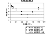
- FIG. 5 is a diagram showing the improvement rate of the radio noise performance according to the seal diameter D of the resistor 3 in the middle frequency region (100 MHz).
- the seal diameter D (refer FIG. 2) which shows the diameter of the resistor 3 about five typical samples (sample No. 23, 24, 25, 26, 27) among the samples shown in FIG.
- the rate of improvement in radio noise performance was obtained by changing the value.
- Each value shown in FIG. 5 shows no difference between the center electrode side resistance value R1 and the terminal metal fitting side resistance value R2, and the sample No. with a seal diameter D of 3.9 mm.
- the improvement rate of the attenuation rate with respect to the attenuation rate of 27 radio noises is shown. According to the evaluation results shown in FIG.
- the resistance value of the resistor 3 arranged in the shaft hole 12 is distributed, and the resistance value of the center electrode side resistor 3b close to the spark gap is set on the terminal fitting side. It is larger than the resistance value of the resistance portion 3a. Therefore, the level of radio noise generated with spark discharge can be effectively suppressed. Moreover, since it is not necessary to change the whole resistance value of the resistor 3, it becomes possible to suppress that a flying performance falls. Conventionally, it is known that when the resistance value of the entire resistor 3 is increased, low frequency radio noise is suppressed, and when the length of the resistor 3 along the axial direction OD is increased, high frequency radio noise is suppressed. However, in the present embodiment, by making the resistance value of the center electrode side resistance portion 3b larger than the resistance value of the terminal metal fitting side resistance portion 3a, as shown in FIG. In addition, the level of radio noise can be reduced in a wide frequency range. *
- the center electrode side resistance value R1 is set to 0.5 k ⁇ or more, preferably 1.0 k ⁇ or more larger than the terminal fitting side resistance value R2, and the terminal fitting side resistance value is set to 100 ⁇ or more.
- the diameter of the resistor 3 is set to 2.9 mm or less, it is possible to more effectively reduce the level of radio noise.
- connection portion 2 is configured such that the glass sealing materials (upper sealing material 4a and lower sealing material 4b) are arranged at both ends of the resistor 3, respectively.
- the resistor 3 and the terminal fitting 40 are in direct contact with each other, and the resistor 3 and the center electrode 20 are in direct contact while omitting both the upper seal material 4a and the lower seal material 4b. It is.
- the interface C can be a cross section on the most distal end side of the portion where the resistor 3 and the terminal fitting 40 are in contact with each other.
- the interface A can be a cross section on the most rear end side of the portion where the resistor 3 and the center electrode 20 are in contact.
- the resistor 3 has a substantially cylindrical shape, and the seal diameter is uniform in the axial direction OD.
- the seal diameter is uniform between the terminal metal part side resistance part 3a and the center electrode side resistance part 3b, the center electrode side of the terminal metal part side resistance part 3a is not changed without changing the material of the resistor 3 as a whole.
- the resistance value of the resistance portion 3b may be increased.
Landscapes
- Chemical & Material Sciences (AREA)
- Engineering & Computer Science (AREA)
- Combustion & Propulsion (AREA)
- Spark Plugs (AREA)
Abstract
Description
シール材4bと抵抗体3の材料粉末を溶融させ、その後冷却する。こうすることで、軸孔12内において上シール材4aと下シール材4bと抵抗体3とが凝固し、中心電極20がおよび端子金具40が軸孔12内に固着される。
3…抵抗体
3a…端子金具側抵抗部
3b…中心電極側抵抗部
4a…上シール材
4b…下シール材
5…ガスケット
6…リング部材
8…板パッキン
9…タルク
10…絶縁碍子
12…軸孔
13…脚長部
15…段部
17…先端側胴部
18…後端側胴部
19…鍔部
20…中心電極
21…電極母材
22…芯材
30…接地電極
40…端子金具
50…主体金具
51…工具係合部
52…取付ネジ部
53…加締部
54…シール部
55…座面
56…段部
58…圧縮変形部
59…ネジ首
100…スパークプラグ
200…エンジンヘッド
201…取付ネジ孔
205…開口周縁部
501…挿入孔
Claims (6)
- 軸線方向に沿った軸孔を有する絶縁体と、前記軸孔の一端側に設けられた中心電極と、
前記軸孔の他端側に設けられた端子金具と、前記軸孔内において前記中心電極と前記端子金具とを電気的に接続する接続部を有するスパークプラグであって、
前記接続部は抵抗体を含み、
前記軸線方向における前記抵抗体の中央より前記中心電極側の抵抗値である中心電極側抵抗値が、前記中央より前記端子金具側の抵抗値である端子金具側抵抗値よりも大きいことを特徴とするスパークプラグ。 - 請求項1に記載のスパークプラグであって、
前記軸線方向における前記抵抗体の中央より前記中心電極側を構成する材料の抵抗値が、前記中央より前記端子金具側を構成する材料の抵抗値よりも大きいことを特徴とするスパークプラグ。 - 請求項1または請求項2に記載のスパークプラグであって、
前記中心電極側抵抗値が前記端子金具側抵抗値よりも0.5kΩ以上大きいことを特徴とするスパークプラグ。 - 請求項1から請求項3までのいずれか一項に記載のスパークプラグであって、
前記中心電極側抵抗値が前記端子金具側抵抗値よりも1.0kΩ以上大きいことを特徴とするスパークプラグ。 - 請求項1から請求項4までのいずれか一項に記載のスパークプラグであって、
前記端子金具側抵抗値が100Ω以上であることを特徴とするスパークプラグ。 - 請求項1から請求項5までのいずれか一項に記載のスパークプラグであって、
前記抵抗体は略円柱状であり、前記抵抗体の直径が、2.9mm以下であることを特徴とするスパークプラグ。
Priority Applications (4)
| Application Number | Priority Date | Filing Date | Title |
|---|---|---|---|
| US13/993,711 US9093824B2 (en) | 2010-12-17 | 2011-09-06 | Spark plug |
| KR20137018449A KR101508452B1 (ko) | 2010-12-17 | 2011-09-06 | 스파크 플러그 |
| CN201180060683.4A CN103262369B (zh) | 2010-12-17 | 2011-09-06 | 火花塞 |
| EP11848027.6A EP2654145B1 (en) | 2010-12-17 | 2011-09-06 | Spark plug |
Applications Claiming Priority (2)
| Application Number | Priority Date | Filing Date | Title |
|---|---|---|---|
| JP2010281274A JP4901990B1 (ja) | 2010-12-17 | 2010-12-17 | スパークプラグ |
| JP2010-281274 | 2010-12-17 |
Publications (1)
| Publication Number | Publication Date |
|---|---|
| WO2012081147A1 true WO2012081147A1 (ja) | 2012-06-21 |
Family
ID=46060699
Family Applications (1)
| Application Number | Title | Priority Date | Filing Date |
|---|---|---|---|
| PCT/JP2011/004985 Ceased WO2012081147A1 (ja) | 2010-12-17 | 2011-09-06 | スパークプラグ |
Country Status (6)
| Country | Link |
|---|---|
| US (1) | US9093824B2 (ja) |
| EP (1) | EP2654145B1 (ja) |
| JP (1) | JP4901990B1 (ja) |
| KR (1) | KR101508452B1 (ja) |
| CN (1) | CN103262369B (ja) |
| WO (1) | WO2012081147A1 (ja) |
Cited By (2)
| Publication number | Priority date | Publication date | Assignee | Title |
|---|---|---|---|---|
| CN103715612A (zh) * | 2012-10-01 | 2014-04-09 | 日本特殊陶业株式会社 | 火花塞 |
| EP3041094A4 (en) * | 2013-08-29 | 2017-04-19 | NGK Spark Plug Co., Ltd. | Spark plug |
Families Citing this family (7)
| Publication number | Priority date | Publication date | Assignee | Title |
|---|---|---|---|---|
| DE102010063752B4 (de) | 2010-12-21 | 2024-11-21 | Robert Bosch Gmbh | Zündkerze für hohe Belastungen |
| KR101777494B1 (ko) | 2014-02-07 | 2017-09-11 | 니혼도꾸슈도교 가부시키가이샤 | 스파크 플러그 |
| JP5902757B2 (ja) * | 2014-06-24 | 2016-04-13 | 日本特殊陶業株式会社 | スパークプラグ |
| JP6350193B2 (ja) | 2014-10-07 | 2018-07-04 | 株式会社デンソー | 内燃機関用のスパークプラグ |
| DE112016000742B4 (de) | 2015-02-12 | 2022-06-02 | Denso Corporation | Zündkerze für eine Verbrennungskraftmaschine |
| JP6657977B2 (ja) | 2015-02-12 | 2020-03-04 | 株式会社デンソー | 内燃機関用のスパークプラグ |
| CN115699484B (zh) * | 2020-09-16 | 2024-04-16 | 日本特殊陶业株式会社 | 火花塞 |
Citations (5)
| Publication number | Priority date | Publication date | Assignee | Title |
|---|---|---|---|---|
| JPS4919236A (ja) * | 1972-06-16 | 1974-02-20 | ||
| JPS5717586A (en) * | 1980-07-04 | 1982-01-29 | Nissan Motor | Noise preventive ignition plug |
| JPH05152053A (ja) | 1991-11-30 | 1993-06-18 | Ngk Spark Plug Co Ltd | 内燃機関用スパークプラグ |
| JPH11233232A (ja) | 1997-04-23 | 1999-08-27 | Ngk Spark Plug Co Ltd | 抵抗体入りスパークプラグ、スパークプラグ用抵抗体組成物及び抵抗体入りスパークプラグの製造方法 |
| JP2006066086A (ja) | 2004-08-24 | 2006-03-09 | Denso Corp | 内燃機関用のスパークプラグ |
Family Cites Families (8)
| Publication number | Priority date | Publication date | Assignee | Title |
|---|---|---|---|---|
| JPS5746634B2 (ja) * | 1974-05-10 | 1982-10-04 | ||
| JPS53107695A (en) | 1977-03-02 | 1978-09-19 | Ngk Spark Plug Co | Resistance body composition for ignition plug containing resistance |
| US4224554A (en) * | 1978-05-20 | 1980-09-23 | Ngk Spark Plug Co., Ltd. | Spark plug having a low noise level |
| JP3589747B2 (ja) * | 1995-07-04 | 2004-11-17 | 株式会社テクニカルアドバンス | ポンプ用タイマー、ポンプ、照明具及び鑑賞魚用装置 |
| JPH11339925A (ja) * | 1998-05-26 | 1999-12-10 | Ngk Spark Plug Co Ltd | スパークプラグ |
| EP1677399B1 (en) * | 2004-12-28 | 2012-02-15 | Ngk Spark Plug Co., Ltd | Spark plug |
| US8049399B2 (en) * | 2006-07-21 | 2011-11-01 | Enerpulse, Inc. | High power discharge fuel ignitor |
| JP5152053B2 (ja) | 2009-03-17 | 2013-02-27 | セイコーエプソン株式会社 | 液滴吐出装置、液滴吐出方法、及びカラーフィルターの製造方法 |
-
2010
- 2010-12-17 JP JP2010281274A patent/JP4901990B1/ja active Active
-
2011
- 2011-09-06 WO PCT/JP2011/004985 patent/WO2012081147A1/ja not_active Ceased
- 2011-09-06 EP EP11848027.6A patent/EP2654145B1/en active Active
- 2011-09-06 CN CN201180060683.4A patent/CN103262369B/zh active Active
- 2011-09-06 KR KR20137018449A patent/KR101508452B1/ko not_active Expired - Fee Related
- 2011-09-06 US US13/993,711 patent/US9093824B2/en active Active
Patent Citations (5)
| Publication number | Priority date | Publication date | Assignee | Title |
|---|---|---|---|---|
| JPS4919236A (ja) * | 1972-06-16 | 1974-02-20 | ||
| JPS5717586A (en) * | 1980-07-04 | 1982-01-29 | Nissan Motor | Noise preventive ignition plug |
| JPH05152053A (ja) | 1991-11-30 | 1993-06-18 | Ngk Spark Plug Co Ltd | 内燃機関用スパークプラグ |
| JPH11233232A (ja) | 1997-04-23 | 1999-08-27 | Ngk Spark Plug Co Ltd | 抵抗体入りスパークプラグ、スパークプラグ用抵抗体組成物及び抵抗体入りスパークプラグの製造方法 |
| JP2006066086A (ja) | 2004-08-24 | 2006-03-09 | Denso Corp | 内燃機関用のスパークプラグ |
Cited By (3)
| Publication number | Priority date | Publication date | Assignee | Title |
|---|---|---|---|---|
| CN103715612A (zh) * | 2012-10-01 | 2014-04-09 | 日本特殊陶业株式会社 | 火花塞 |
| EP3041094A4 (en) * | 2013-08-29 | 2017-04-19 | NGK Spark Plug Co., Ltd. | Spark plug |
| KR101747613B1 (ko) | 2013-08-29 | 2017-06-14 | 니혼도꾸슈도교 가부시키가이샤 | 점화 플러그 |
Also Published As
| Publication number | Publication date |
|---|---|
| JP4901990B1 (ja) | 2012-03-21 |
| EP2654145B1 (en) | 2019-12-25 |
| JP2012129132A (ja) | 2012-07-05 |
| KR101508452B1 (ko) | 2015-04-07 |
| EP2654145A1 (en) | 2013-10-23 |
| CN103262369A (zh) | 2013-08-21 |
| CN103262369B (zh) | 2014-10-15 |
| US20130264939A1 (en) | 2013-10-10 |
| KR20130093681A (ko) | 2013-08-22 |
| EP2654145A4 (en) | 2015-03-25 |
| US9093824B2 (en) | 2015-07-28 |
Similar Documents
| Publication | Publication Date | Title |
|---|---|---|
| JP4901990B1 (ja) | スパークプラグ | |
| US8624473B2 (en) | Spark plug | |
| US11456578B2 (en) | Spark plug | |
| JP5134633B2 (ja) | 内燃機関用スパークプラグ及びその製造方法 | |
| US20130307402A1 (en) | Spark plug | |
| US8987981B2 (en) | Spark plug | |
| JP5608204B2 (ja) | スパークプラグ | |
| EP2020713A1 (en) | Spark plug for internal combustion engine and method of manufacturing the same | |
| EP2624382B1 (en) | Spark plug and manufacturing method for same | |
| CN102308447A (zh) | 内燃机用火花塞及其制造方法 | |
| JP5001963B2 (ja) | 内燃機関用スパークプラグ。 | |
| JP2009129645A (ja) | スパークプラグ | |
| JP6158283B2 (ja) | スパークプラグ | |
| JP5616858B2 (ja) | 点火プラグ | |
| KR101441836B1 (ko) | 스파크 플러그 | |
| US10431961B2 (en) | Spark plug | |
| EP2634872B1 (en) | Spark plug | |
| JP5642129B2 (ja) | スパークプラグ | |
| JP5683409B2 (ja) | スパークプラグおよびスパークプラグの製造方法 | |
| JP2009187840A (ja) | スパークプラグ | |
| JP2010165698A5 (ja) | ||
| JP2010165698A (ja) | スパークプラグ | |
| JP2015005388A (ja) | スパークプラグの製造方法 |
Legal Events
| Date | Code | Title | Description |
|---|---|---|---|
| 121 | Ep: the epo has been informed by wipo that ep was designated in this application |
Ref document number: 11848027 Country of ref document: EP Kind code of ref document: A1 |
|
| WWE | Wipo information: entry into national phase |
Ref document number: 13993711 Country of ref document: US |
|
| NENP | Non-entry into the national phase |
Ref country code: DE |
|
| WWE | Wipo information: entry into national phase |
Ref document number: 2011848027 Country of ref document: EP |
|
| ENP | Entry into the national phase |
Ref document number: 20137018449 Country of ref document: KR Kind code of ref document: A |