WO2012081152A1 - ポンプ装置 - Google Patents
ポンプ装置 Download PDFInfo
- Publication number
- WO2012081152A1 WO2012081152A1 PCT/JP2011/005674 JP2011005674W WO2012081152A1 WO 2012081152 A1 WO2012081152 A1 WO 2012081152A1 JP 2011005674 W JP2011005674 W JP 2011005674W WO 2012081152 A1 WO2012081152 A1 WO 2012081152A1
- Authority
- WO
- WIPO (PCT)
- Prior art keywords
- return
- channel
- suction tube
- delivery channel
- fluid
- Prior art date
- Legal status (The legal status is an assumption and is not a legal conclusion. Google has not performed a legal analysis and makes no representation as to the accuracy of the status listed.)
- Ceased
Links
Images




Classifications
-
- F—MECHANICAL ENGINEERING; LIGHTING; HEATING; WEAPONS; BLASTING
- F01—MACHINES OR ENGINES IN GENERAL; ENGINE PLANTS IN GENERAL; STEAM ENGINES
- F01N—GAS-FLOW SILENCERS OR EXHAUST APPARATUS FOR MACHINES OR ENGINES IN GENERAL; GAS-FLOW SILENCERS OR EXHAUST APPARATUS FOR INTERNAL-COMBUSTION ENGINES
- F01N3/00—Exhaust or silencing apparatus having means for purifying, rendering innocuous, or otherwise treating exhaust
- F01N3/08—Exhaust or silencing apparatus having means for purifying, rendering innocuous, or otherwise treating exhaust for rendering innocuous
-
- F—MECHANICAL ENGINEERING; LIGHTING; HEATING; WEAPONS; BLASTING
- F01—MACHINES OR ENGINES IN GENERAL; ENGINE PLANTS IN GENERAL; STEAM ENGINES
- F01N—GAS-FLOW SILENCERS OR EXHAUST APPARATUS FOR MACHINES OR ENGINES IN GENERAL; GAS-FLOW SILENCERS OR EXHAUST APPARATUS FOR INTERNAL-COMBUSTION ENGINES
- F01N3/00—Exhaust or silencing apparatus having means for purifying, rendering innocuous, or otherwise treating exhaust
- F01N3/08—Exhaust or silencing apparatus having means for purifying, rendering innocuous, or otherwise treating exhaust for rendering innocuous
- F01N3/10—Exhaust or silencing apparatus having means for purifying, rendering innocuous, or otherwise treating exhaust for rendering innocuous by thermal or catalytic conversion of noxious components of exhaust
- F01N3/18—Exhaust or silencing apparatus having means for purifying, rendering innocuous, or otherwise treating exhaust for rendering innocuous by thermal or catalytic conversion of noxious components of exhaust characterised by methods of operation; Control
- F01N3/20—Exhaust or silencing apparatus having means for purifying, rendering innocuous, or otherwise treating exhaust for rendering innocuous by thermal or catalytic conversion of noxious components of exhaust characterised by methods of operation; Control specially adapted for catalytic conversion
- F01N3/206—Adding periodically or continuously substances to exhaust gases for promoting purification, e.g. catalytic material in liquid form, NOx reducing agents
- F01N3/208—Control of selective catalytic reduction [SCR], e.g. by adjusting the dosing of reducing agent
-
- F—MECHANICAL ENGINEERING; LIGHTING; HEATING; WEAPONS; BLASTING
- F01—MACHINES OR ENGINES IN GENERAL; ENGINE PLANTS IN GENERAL; STEAM ENGINES
- F01N—GAS-FLOW SILENCERS OR EXHAUST APPARATUS FOR MACHINES OR ENGINES IN GENERAL; GAS-FLOW SILENCERS OR EXHAUST APPARATUS FOR INTERNAL-COMBUSTION ENGINES
- F01N3/00—Exhaust or silencing apparatus having means for purifying, rendering innocuous, or otherwise treating exhaust
- F01N3/08—Exhaust or silencing apparatus having means for purifying, rendering innocuous, or otherwise treating exhaust for rendering innocuous
- F01N3/10—Exhaust or silencing apparatus having means for purifying, rendering innocuous, or otherwise treating exhaust for rendering innocuous by thermal or catalytic conversion of noxious components of exhaust
- F01N3/18—Exhaust or silencing apparatus having means for purifying, rendering innocuous, or otherwise treating exhaust for rendering innocuous by thermal or catalytic conversion of noxious components of exhaust characterised by methods of operation; Control
- F01N3/20—Exhaust or silencing apparatus having means for purifying, rendering innocuous, or otherwise treating exhaust for rendering innocuous by thermal or catalytic conversion of noxious components of exhaust characterised by methods of operation; Control specially adapted for catalytic conversion
- F01N3/206—Adding periodically or continuously substances to exhaust gases for promoting purification, e.g. catalytic material in liquid form, NOx reducing agents
- F01N3/2066—Selective catalytic reduction [SCR]
-
- F—MECHANICAL ENGINEERING; LIGHTING; HEATING; WEAPONS; BLASTING
- F01—MACHINES OR ENGINES IN GENERAL; ENGINE PLANTS IN GENERAL; STEAM ENGINES
- F01N—GAS-FLOW SILENCERS OR EXHAUST APPARATUS FOR MACHINES OR ENGINES IN GENERAL; GAS-FLOW SILENCERS OR EXHAUST APPARATUS FOR INTERNAL-COMBUSTION ENGINES
- F01N2610/00—Adding substances to exhaust gases
- F01N2610/02—Adding substances to exhaust gases the substance being ammonia or urea
-
- F—MECHANICAL ENGINEERING; LIGHTING; HEATING; WEAPONS; BLASTING
- F01—MACHINES OR ENGINES IN GENERAL; ENGINE PLANTS IN GENERAL; STEAM ENGINES
- F01N—GAS-FLOW SILENCERS OR EXHAUST APPARATUS FOR MACHINES OR ENGINES IN GENERAL; GAS-FLOW SILENCERS OR EXHAUST APPARATUS FOR INTERNAL-COMBUSTION ENGINES
- F01N2610/00—Adding substances to exhaust gases
- F01N2610/14—Arrangements for the supply of substances, e.g. conduits
-
- F—MECHANICAL ENGINEERING; LIGHTING; HEATING; WEAPONS; BLASTING
- F01—MACHINES OR ENGINES IN GENERAL; ENGINE PLANTS IN GENERAL; STEAM ENGINES
- F01N—GAS-FLOW SILENCERS OR EXHAUST APPARATUS FOR MACHINES OR ENGINES IN GENERAL; GAS-FLOW SILENCERS OR EXHAUST APPARATUS FOR INTERNAL-COMBUSTION ENGINES
- F01N2610/00—Adding substances to exhaust gases
- F01N2610/14—Arrangements for the supply of substances, e.g. conduits
- F01N2610/1406—Storage means for substances, e.g. tanks or reservoirs
-
- F—MECHANICAL ENGINEERING; LIGHTING; HEATING; WEAPONS; BLASTING
- F01—MACHINES OR ENGINES IN GENERAL; ENGINE PLANTS IN GENERAL; STEAM ENGINES
- F01N—GAS-FLOW SILENCERS OR EXHAUST APPARATUS FOR MACHINES OR ENGINES IN GENERAL; GAS-FLOW SILENCERS OR EXHAUST APPARATUS FOR INTERNAL-COMBUSTION ENGINES
- F01N2610/00—Adding substances to exhaust gases
- F01N2610/14—Arrangements for the supply of substances, e.g. conduits
- F01N2610/1433—Pumps
-
- F—MECHANICAL ENGINEERING; LIGHTING; HEATING; WEAPONS; BLASTING
- F01—MACHINES OR ENGINES IN GENERAL; ENGINE PLANTS IN GENERAL; STEAM ENGINES
- F01N—GAS-FLOW SILENCERS OR EXHAUST APPARATUS FOR MACHINES OR ENGINES IN GENERAL; GAS-FLOW SILENCERS OR EXHAUST APPARATUS FOR INTERNAL-COMBUSTION ENGINES
- F01N2610/00—Adding substances to exhaust gases
- F01N2610/14—Arrangements for the supply of substances, e.g. conduits
- F01N2610/1433—Pumps
- F01N2610/144—Control thereof
-
- F—MECHANICAL ENGINEERING; LIGHTING; HEATING; WEAPONS; BLASTING
- F01—MACHINES OR ENGINES IN GENERAL; ENGINE PLANTS IN GENERAL; STEAM ENGINES
- F01N—GAS-FLOW SILENCERS OR EXHAUST APPARATUS FOR MACHINES OR ENGINES IN GENERAL; GAS-FLOW SILENCERS OR EXHAUST APPARATUS FOR INTERNAL-COMBUSTION ENGINES
- F01N2610/00—Adding substances to exhaust gases
- F01N2610/14—Arrangements for the supply of substances, e.g. conduits
- F01N2610/1473—Overflow or return means for the substances, e.g. conduits or valves for the return path
-
- F—MECHANICAL ENGINEERING; LIGHTING; HEATING; WEAPONS; BLASTING
- F01—MACHINES OR ENGINES IN GENERAL; ENGINE PLANTS IN GENERAL; STEAM ENGINES
- F01N—GAS-FLOW SILENCERS OR EXHAUST APPARATUS FOR MACHINES OR ENGINES IN GENERAL; GAS-FLOW SILENCERS OR EXHAUST APPARATUS FOR INTERNAL-COMBUSTION ENGINES
- F01N2900/00—Details of electrical control or of the monitoring of the exhaust gas treating apparatus
- F01N2900/06—Parameters used for exhaust control or diagnosing
- F01N2900/18—Parameters used for exhaust control or diagnosing said parameters being related to the system for adding a substance into the exhaust
- F01N2900/1806—Properties of reducing agent or dosing system
- F01N2900/1812—Flow rate
-
- F—MECHANICAL ENGINEERING; LIGHTING; HEATING; WEAPONS; BLASTING
- F01—MACHINES OR ENGINES IN GENERAL; ENGINE PLANTS IN GENERAL; STEAM ENGINES
- F01N—GAS-FLOW SILENCERS OR EXHAUST APPARATUS FOR MACHINES OR ENGINES IN GENERAL; GAS-FLOW SILENCERS OR EXHAUST APPARATUS FOR INTERNAL-COMBUSTION ENGINES
- F01N2900/00—Details of electrical control or of the monitoring of the exhaust gas treating apparatus
- F01N2900/06—Parameters used for exhaust control or diagnosing
- F01N2900/18—Parameters used for exhaust control or diagnosing said parameters being related to the system for adding a substance into the exhaust
- F01N2900/1806—Properties of reducing agent or dosing system
- F01N2900/1818—Concentration of the reducing agent
-
- F—MECHANICAL ENGINEERING; LIGHTING; HEATING; WEAPONS; BLASTING
- F01—MACHINES OR ENGINES IN GENERAL; ENGINE PLANTS IN GENERAL; STEAM ENGINES
- F01N—GAS-FLOW SILENCERS OR EXHAUST APPARATUS FOR MACHINES OR ENGINES IN GENERAL; GAS-FLOW SILENCERS OR EXHAUST APPARATUS FOR INTERNAL-COMBUSTION ENGINES
- F01N2900/00—Details of electrical control or of the monitoring of the exhaust gas treating apparatus
- F01N2900/06—Parameters used for exhaust control or diagnosing
- F01N2900/18—Parameters used for exhaust control or diagnosing said parameters being related to the system for adding a substance into the exhaust
- F01N2900/1806—Properties of reducing agent or dosing system
- F01N2900/1822—Pump parameters
-
- Y—GENERAL TAGGING OF NEW TECHNOLOGICAL DEVELOPMENTS; GENERAL TAGGING OF CROSS-SECTIONAL TECHNOLOGIES SPANNING OVER SEVERAL SECTIONS OF THE IPC; TECHNICAL SUBJECTS COVERED BY FORMER USPC CROSS-REFERENCE ART COLLECTIONS [XRACs] AND DIGESTS
- Y02—TECHNOLOGIES OR APPLICATIONS FOR MITIGATION OR ADAPTATION AGAINST CLIMATE CHANGE
- Y02A—TECHNOLOGIES FOR ADAPTATION TO CLIMATE CHANGE
- Y02A50/00—TECHNOLOGIES FOR ADAPTATION TO CLIMATE CHANGE in human health protection, e.g. against extreme weather
- Y02A50/20—Air quality improvement or preservation, e.g. vehicle emission control or emission reduction by using catalytic converters
-
- Y—GENERAL TAGGING OF NEW TECHNOLOGICAL DEVELOPMENTS; GENERAL TAGGING OF CROSS-SECTIONAL TECHNOLOGIES SPANNING OVER SEVERAL SECTIONS OF THE IPC; TECHNICAL SUBJECTS COVERED BY FORMER USPC CROSS-REFERENCE ART COLLECTIONS [XRACs] AND DIGESTS
- Y02—TECHNOLOGIES OR APPLICATIONS FOR MITIGATION OR ADAPTATION AGAINST CLIMATE CHANGE
- Y02T—CLIMATE CHANGE MITIGATION TECHNOLOGIES RELATED TO TRANSPORTATION
- Y02T10/00—Road transport of goods or passengers
- Y02T10/10—Internal combustion engine [ICE] based vehicles
- Y02T10/12—Improving ICE efficiencies
-
- Y—GENERAL TAGGING OF NEW TECHNOLOGICAL DEVELOPMENTS; GENERAL TAGGING OF CROSS-SECTIONAL TECHNOLOGIES SPANNING OVER SEVERAL SECTIONS OF THE IPC; TECHNICAL SUBJECTS COVERED BY FORMER USPC CROSS-REFERENCE ART COLLECTIONS [XRACs] AND DIGESTS
- Y10—TECHNICAL SUBJECTS COVERED BY FORMER USPC
- Y10T—TECHNICAL SUBJECTS COVERED BY FORMER US CLASSIFICATION
- Y10T137/00—Fluid handling
- Y10T137/7722—Line condition change responsive valves
- Y10T137/7736—Consistency responsive
Definitions
- the present invention relates to a pump device used in, for example, a selective catalyst reduction type exhaust purification device, and more particularly to a pump device having an identification function and capable of reducing the price.
- a selective catalytic reduction (SCR) type exhaust purification device that reduces nitrogen oxide (NOx) in exhaust gas with ammonia is known as a device that purifies engine exhaust by post-processing.
- SCR selective catalytic reduction
- a nitrogen oxide (NOx) reduction catalyst is installed in the exhaust passage, a urea water supply device is provided upstream of the nitrogen oxide (NOx) reduction catalyst, and an ammonia purification oxidation catalyst is provided downstream.
- a catalyst is installed. Ammonia is generated by hydrolysis of urea added to the exhaust gas by the supply device, and this ammonia is supplied as a reducing agent to the nitrogen oxide (NOx) reduction catalyst.
- ammonia (slip ammonia) that has passed through the nitrogen oxide (NOx) reduction catalyst without contributing to the reduction of nitrogen oxide (NOx) is oxidized and purified by the ammonia purification catalyst before being released into the atmosphere. .
- the selective catalytic reduction (SCR) type exhaust purification device requires a separate device from the pump called the identification sensor in addition to the suction pump in the container using the specified liquid.
- the liquid used was managed by using the apparatus (for example, refer patent documents 1 and 2).
- the present invention has been made to solve such a conventional problem, and an object of the present invention is to provide a pump device having an identification function and capable of reducing the price.
- a pump device includes a suction tube provided with a flow meter, a pump for connecting a return channel and a delivery channel to the suction tube, a return tube connected to the return channel, and a suction tube and a delivery channel. And a control device for discriminating the fluid by the flow rate difference of the flowmeter.
- the solenoid valve closes the delivery channel when liquid flows in, measures the flow rate of the fluid sucked from the suction tube with a flow meter, and returns the fluid to the return tube through the return channel.
- control device When the control device identifies that the fluid is the intended fluid, it opens the solenoid valve to supply the fluid to the delivery channel.
- the pump device according to the present invention is mounted on an automobile equipped with a selective catalytic reduction (SCR) type exhaust purification device, and includes a container for storing urea, and the solenoid valve is a delivery channel when the engine is started.
- SCR selective catalytic reduction
- the flow rate of urea sucked from the suction tube is measured by a flow meter, and urea is returned to the return tube through the return channel.
- control device When the control device identifies urea as the target urea, it opens the solenoid valve to supply urea to the delivery channel.
- the pump has a combine fan that is coaxially connected to the return channel and the delivery channel.
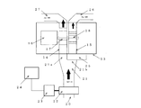
- FIG. 1 It is a partially cutaway side view showing a pump device according to an embodiment of the present invention. It is a block diagram of FIG. It is explanatory drawing which shows the principal part of FIG. It is a perspective view of the combine fan used for FIG. It is explanatory drawing which shows the pump apparatus which concerns on another embodiment of this invention.
- FIG. 1 to 4 show an example in which a pump device 1 according to an embodiment of the present invention is applied to an automobile equipped with a selective catalytic reduction (SCR) type exhaust purification device.
- SCR selective catalytic reduction
- the pump device 1 includes a pump module 12 placed in the opening 11 of the container 10 for storing urea.
- the pump module 12 includes a return channel 14 connected to a return tube 27, a delivery channel 15 connected to a muffler supply pipe 26, a first fan 17 disposed in the return channel 14, and a delivery channel 15
- a pump 13 having a second fan 18 disposed coaxially with the first fan 17 and a motor 16 for rotating the first fan 17 and the second fan 18 is provided.
- the first fan 17 and the second fan 18 are composed of combine fans as shown in FIG.
- the main reason for adopting the combine fan for the pump 13 is that a certain flow rate is required for the flow rate measurement, but a large flow rate difference of each system due to the small amount of urea used as the SCR device is driven by one. This is because it is covered by a machine.
- the return channel 14 and the delivery channel 15 are respectively connected to the pipe lines 21a and 21b of the bifurcated connection pipe 21 formed to expand to the downstream side provided at the end of the suction tube 20 disposed in the container 10. Connected in parallel.
- the delivery channel 15 is provided with an electromagnetic valve 25 at a boundary portion between the bifurcated connection pipe 21 and one pipe line 21b.
- the opening and closing of the electromagnetic valve 25 is controlled by a control device 24 described later.
- the flow tube 22 is disposed in the suction tube 20.
- the flow meter 22 is configured to communicate with a control device (CPU) 24 and identify whether or not the fluid flowing in the suction tube 20 is urea based on the flow rate difference.
- a control device CPU
- control device 24 calculates the flow velocity from the flow rate per unit time (depending on the pump capacity, but about 10 seconds to 1 minute) and the cross-sectional area of the return tube 27.
- the control device 24 closes the electromagnetic valve 25, and the pump 13 causes the urea sucked in the suction tube 20 to flow from the return channel 14 only to the return tube 27.
- the control device 24 opens the electromagnetic valve 25 to both the return tube 27 and the supply pipe 26 to the muffler. It is a flowing mechanism.
- a return tube 27 disposed in the container 10 is connected to the return channel 14.
- the liquid level level gauge 28 is provided in the container 10.
- the control device 24 closes the electromagnetic valve 25 ( 100% return), the motor 16 of the pump 13 is driven for 20 to 30 seconds, for example, and the flow velocity is measured by the flow meter 22 (drive time: sampling time depends on the performance of the pump and the accuracy of the flow meter used) Therefore, it is a reference value).
- the SCR system can be used. After the system receives a signal to inject urea into the muffler supply pipe 26 after READY (this control is as before), the control device 24 opens the solenoid valve 25 and several percent of the total flow rate reaches the muffler. It is supplied to the supply pipe 26 side.
- the liquid is always monitored by the control device 24 through the flow meter 25, and when an incorrect liquid is mixed after the engine is started, the control device 24 immediately closes the solenoid valve 2, and performs re-measurement and liquid determination work. Still, in the case of NG, an abnormal signal is transmitted to the meter. The output of the pump 13 is controlled by the control device 24.
- the control device 24 always monitors the aqueous solution based on the flow rate from the flow meter 22, and closes the solenoid valve 25 when an intentionally mixed liquid (light oil or oil) is intentionally mixed after starting the engine to prevent accidents. Since a sufficient flow rate cannot be obtained at a normal urea use level, it is possible to obtain a flow rate necessary for detection by returning to the return tube 27 side.
- the flow rate of the liquid sucked up by the pump 13 varies depending on the density of the liquid when passing through the flow meter 25, but the measured flow rate is previously stored in the control device 24. If it is different from the set flow rate, it is returned to the return tube 27 through the electromagnetic valve 25. This is repeated several times, and if the initial set flow velocity cannot be obtained, it is determined that there is an abnormality (undesignated liquid filling) and an abnormality signal is output.
- the total supply amount of urea is calculated by, for example, the cross-sectional area of the pipe line, the number of rotations of the motor, and the valve ON / OFF. For example, even if it is supplied to the atomizer side, there is a return amount, so it is not simply added. It is possible to set the actual supply amount as data.
- FIG. 5 shows an example in which the milk fat content is discriminated based on the information obtained from the flow meter 22A.
- the present invention can be applied when separating two or more mixed liquids such as an oil / water separator and a waste liquid storage tank.
Landscapes
- Engineering & Computer Science (AREA)
- Chemical & Material Sciences (AREA)
- Chemical Kinetics & Catalysis (AREA)
- Combustion & Propulsion (AREA)
- Mechanical Engineering (AREA)
- General Engineering & Computer Science (AREA)
- Health & Medical Sciences (AREA)
- Toxicology (AREA)
- Exhaust Gas After Treatment (AREA)
Abstract
Description
10 容器
13 ポンプ
14 リターンチャネル
15 デリバリチャネル
16 モータ
20 サクションチューブ
22 流量計
23 モータ
24 制御装置
25 電磁弁
26 マフラーへの供給管
27 リターンチューブ
Claims (3)
- サクションチューブと、
前記サクションチューブに設けられる流量計と、
リターンチャネルとデリバリチャネルとを有し、前記リターンチャネルと前記デリバリチャネルとを前記サクションチューブと接続させるポンプと、
前記リターンチャネルに接続するリターンチューブと、
前記サクションチューブと前記デリバリチャネルとの間に設けられる電磁弁と、
前記流量計の流速差によって流体を識別する制御装置と
を備え、
前記電磁弁は、前記液体の流入時には前記デリバリチャネルを閉じ、前記サクションチューブから吸い込まれた前記流体の流量を流量計によって測定し前記流体を前記リターンチャネルを介して前記リターンチューブに戻し、
前記制御装置が前記液体を目的とする流体であることを識別したときに、前記電磁弁を開放して前記デリバリチャネルへも流体を供給させる
ことを特徴とするポンプ装置。 - 選択触媒還元(SCR)型の排気浄化装置を搭載した自動車に用いられるポンプ装置において、
尿素を貯留する容器と、
前記容器内に配置されるサクションチューブと、
前記サクションチューブに設けられる流量計と、
前記容器の開口部側に位置し、リターンチャネルとデリバリチャネルとを有し、前記リターンチャネルと前記デリバリチャネルとを前記サクションチューブと接続させるポンプと、
前記容器内に配置され、前記リターンチャネルに接続するリターンチューブと、
前記サクションチューブと前記デリバリチャネルとの間に設けられる電磁弁と、
前記流量計の流速差によって尿素を識別する制御装置と
を備え、
前記電磁弁は、前記自動車のエンジン始動時には前記デリバリチャネルを閉じ、前記サクションチューブから吸い込まれた前記尿素の流量を流量計によって測定し、前記尿素を前記リターンチャネルを介して前記リターンチューブに戻し、
前記制御装置が前記尿素を目的とする尿素であることを識別したときに、前記電磁弁を開放して前記デリバリチャネルへも前記尿素を供給させる
ことを特徴とするポンプ装置。 - 請求項1又は2記載のポンプ装置において、
前記ポンプは、前記リターンチャネルと前記デリバリチャネルとに同軸上に連結するコンバインファンを配置している
ことを特徴とするポンプ装置。
Priority Applications (4)
| Application Number | Priority Date | Filing Date | Title |
|---|---|---|---|
| JP2012548615A JP5679592B2 (ja) | 2010-12-17 | 2011-10-11 | ポンプ装置 |
| EP11848151.4A EP2653682B1 (en) | 2010-12-17 | 2011-10-11 | Pump device |
| CN201180059942.1A CN103261600B (zh) | 2010-12-17 | 2011-10-11 | 泵装置 |
| US13/994,800 US9188038B2 (en) | 2010-12-17 | 2011-10-11 | Pumping device |
Applications Claiming Priority (2)
| Application Number | Priority Date | Filing Date | Title |
|---|---|---|---|
| JP2010-281816 | 2010-12-17 | ||
| JP2010281816 | 2010-12-17 |
Publications (1)
| Publication Number | Publication Date |
|---|---|
| WO2012081152A1 true WO2012081152A1 (ja) | 2012-06-21 |
Family
ID=46244272
Family Applications (1)
| Application Number | Title | Priority Date | Filing Date |
|---|---|---|---|
| PCT/JP2011/005674 Ceased WO2012081152A1 (ja) | 2010-12-17 | 2011-10-11 | ポンプ装置 |
Country Status (5)
| Country | Link |
|---|---|
| US (1) | US9188038B2 (ja) |
| EP (1) | EP2653682B1 (ja) |
| JP (1) | JP5679592B2 (ja) |
| CN (1) | CN103261600B (ja) |
| WO (1) | WO2012081152A1 (ja) |
Families Citing this family (2)
| Publication number | Priority date | Publication date | Assignee | Title |
|---|---|---|---|---|
| KR101882664B1 (ko) | 2014-08-15 | 2018-08-24 | 로베르트 보쉬 게엠베하 | 압력 제어를 갖는 디젤 배기 유체 전달 시스템 |
| CN112377814B (zh) * | 2020-11-12 | 2021-11-30 | 北京工大环能科技有限公司 | 一种流体输送中实现一机多用的系统 |
Citations (4)
| Publication number | Priority date | Publication date | Assignee | Title |
|---|---|---|---|---|
| JPH05118500A (ja) * | 1991-10-24 | 1993-05-14 | Toshiba Corp | 異種流体移送装置 |
| JP2005337969A (ja) | 2004-05-28 | 2005-12-08 | Mitsui Mining & Smelting Co Ltd | 液種識別方法及び液種識別装置 |
| JP2007263949A (ja) | 2006-02-28 | 2007-10-11 | Mitsui Mining & Smelting Co Ltd | 流体識別装置および流体識別方法 |
| JP2008274765A (ja) * | 2007-04-25 | 2008-11-13 | Toyota Motor Corp | 内燃機関の排気浄化装置 |
Family Cites Families (9)
| Publication number | Priority date | Publication date | Assignee | Title |
|---|---|---|---|---|
| JP3687917B2 (ja) * | 2003-10-31 | 2005-08-24 | 日産ディーゼル工業株式会社 | 液体還元剤の濃度及び残量検出装置 |
| JP3686672B1 (ja) * | 2004-12-24 | 2005-08-24 | 日産ディーゼル工業株式会社 | エンジンの排気浄化装置 |
| WO2007086585A1 (ja) * | 2006-01-30 | 2007-08-02 | Mitsui Mining & Smelting Co., Ltd. | 流体識別装置および流体識別方法 |
| US7878183B2 (en) * | 2007-07-17 | 2011-02-01 | Cummins Filtration Ip, Inc. | Apparatus, system, and method to provide air to a doser injector nozzle |
| DE102008060373B4 (de) * | 2008-12-03 | 2023-07-06 | Robert Bosch Gmbh | Abgasreinigungseinrichtung für Kraftahrzeuge |
| JP5051148B2 (ja) * | 2009-02-04 | 2012-10-17 | 株式会社デンソー | 排気浄化システムの異常診断装置 |
| JP4737312B2 (ja) * | 2009-03-10 | 2011-07-27 | 株式会社デンソー | 排気浄化システムの異常診断装置及び排気浄化システム |
| CA2806591A1 (en) * | 2010-08-19 | 2012-02-23 | Dow Global Technologies Llc | Method and devices for heating urea-containing materials in vehicle emission control system |
| US20130000743A1 (en) * | 2011-06-29 | 2013-01-03 | Ti Group Automotive Systems, L.L.C. | Scr fluid distribution and circulation system |
-
2011
- 2011-10-11 JP JP2012548615A patent/JP5679592B2/ja not_active Expired - Fee Related
- 2011-10-11 US US13/994,800 patent/US9188038B2/en not_active Expired - Fee Related
- 2011-10-11 WO PCT/JP2011/005674 patent/WO2012081152A1/ja not_active Ceased
- 2011-10-11 EP EP11848151.4A patent/EP2653682B1/en not_active Not-in-force
- 2011-10-11 CN CN201180059942.1A patent/CN103261600B/zh not_active Expired - Fee Related
Patent Citations (4)
| Publication number | Priority date | Publication date | Assignee | Title |
|---|---|---|---|---|
| JPH05118500A (ja) * | 1991-10-24 | 1993-05-14 | Toshiba Corp | 異種流体移送装置 |
| JP2005337969A (ja) | 2004-05-28 | 2005-12-08 | Mitsui Mining & Smelting Co Ltd | 液種識別方法及び液種識別装置 |
| JP2007263949A (ja) | 2006-02-28 | 2007-10-11 | Mitsui Mining & Smelting Co Ltd | 流体識別装置および流体識別方法 |
| JP2008274765A (ja) * | 2007-04-25 | 2008-11-13 | Toyota Motor Corp | 内燃機関の排気浄化装置 |
Non-Patent Citations (1)
| Title |
|---|
| See also references of EP2653682A4 |
Also Published As
| Publication number | Publication date |
|---|---|
| EP2653682B1 (en) | 2017-12-06 |
| JPWO2012081152A1 (ja) | 2014-05-22 |
| CN103261600B (zh) | 2015-09-30 |
| CN103261600A (zh) | 2013-08-21 |
| JP5679592B2 (ja) | 2015-03-04 |
| EP2653682A1 (en) | 2013-10-23 |
| US20130276913A1 (en) | 2013-10-24 |
| EP2653682A4 (en) | 2016-11-23 |
| US9188038B2 (en) | 2015-11-17 |
Similar Documents
| Publication | Publication Date | Title |
|---|---|---|
| CN109923290B (zh) | 监控废气后处理系统储罐的罐内容物的方法和设备及车辆 | |
| CN102893004B (zh) | NOx传感器诊断装置以及SCR系统 | |
| US7743605B2 (en) | Exhaust emission purifying apparatus for engine | |
| CN102312706B (zh) | 运行用于scr催化转换器的还原剂计量系统的方法 | |
| JP6092627B2 (ja) | タンクから取り除かれた液体の量を決定するための方法 | |
| JP6105403B2 (ja) | 尿素水供給系の診断装置 | |
| JP5478110B2 (ja) | 還元剤の異常検出方法 | |
| CN105408595B (zh) | 运行用于输送液体的装置的方法 | |
| CN103547919B (zh) | 用于运行scr系统的方法和设备 | |
| JP5461057B2 (ja) | 還元剤の異常検出方法 | |
| WO2008044377A1 (fr) | Épurateur de gaz d'échappement de moteur | |
| CN102619602B (zh) | 用于检测scr计量系统中过滤器的加载状态的方法 | |
| CN105189957A (zh) | 带尿素温度合理性诊断的排气处理系统 | |
| JP6142530B2 (ja) | 尿素scr用尿素水消費量診断装置 | |
| JP5679592B2 (ja) | ポンプ装置 | |
| CN102374003A (zh) | 用于监控计量装置的方法 | |
| JP2014512478A (ja) | Scrシステムに付随する容器の還元剤の残留体積を決定するための方法および装置 | |
| CN111271165B (zh) | 用于识别机动车中的储备容器的罐装错误的方法 | |
| CN112262253B (zh) | 注入到机动车辆排出气体处理系统中的液体添加剂的流量的动态监测 | |
| CN102954924B (zh) | 用于确定还原剂溶液的质量的设备和方法 | |
| JP2009281952A (ja) | NOxセンサの異常判定装置 | |
| JP4894765B2 (ja) | 排気浄化装置 | |
| JP2014513234A (ja) | Scrシステム内で投与される還元剤の体積を決定するための方法および装置 | |
| WO2014200413A1 (en) | Method for detection of a blocked flow | |
| SE538383C2 (sv) | Doseringssystem och metod för att övervaka mängden fluid somdoseras av doseringssystemet |
Legal Events
| Date | Code | Title | Description |
|---|---|---|---|
| 121 | Ep: the epo has been informed by wipo that ep was designated in this application |
Ref document number: 11848151 Country of ref document: EP Kind code of ref document: A1 |
|
| ENP | Entry into the national phase |
Ref document number: 2012548615 Country of ref document: JP Kind code of ref document: A |
|
| NENP | Non-entry into the national phase |
Ref country code: DE |
|
| WWE | Wipo information: entry into national phase |
Ref document number: 13994800 Country of ref document: US Ref document number: 2011848151 Country of ref document: EP |