WO2012081287A1 - 排気ポンプに適用可能な固定翼ブレード集合体、及びそれを備えた排気ポンプ - Google Patents
排気ポンプに適用可能な固定翼ブレード集合体、及びそれを備えた排気ポンプ Download PDFInfo
- Publication number
- WO2012081287A1 WO2012081287A1 PCT/JP2011/070800 JP2011070800W WO2012081287A1 WO 2012081287 A1 WO2012081287 A1 WO 2012081287A1 JP 2011070800 W JP2011070800 W JP 2011070800W WO 2012081287 A1 WO2012081287 A1 WO 2012081287A1
- Authority
- WO
- WIPO (PCT)
- Prior art keywords
- blade
- fixed
- fixed blade
- rotor
- blades
- Prior art date
- Legal status (The legal status is an assumption and is not a legal conclusion. Google has not performed a legal analysis and makes no representation as to the accuracy of the status listed.)
- Ceased
Links
Images



Classifications
-
- F—MECHANICAL ENGINEERING; LIGHTING; HEATING; WEAPONS; BLASTING
- F01—MACHINES OR ENGINES IN GENERAL; ENGINE PLANTS IN GENERAL; STEAM ENGINES
- F01D—NON-POSITIVE DISPLACEMENT MACHINES OR ENGINES, e.g. STEAM TURBINES
- F01D9/00—Stators
- F01D9/02—Nozzles; Nozzle boxes; Stator blades; Guide conduits, e.g. individual nozzles
-
- F—MECHANICAL ENGINEERING; LIGHTING; HEATING; WEAPONS; BLASTING
- F04—POSITIVE - DISPLACEMENT MACHINES FOR LIQUIDS; PUMPS FOR LIQUIDS OR ELASTIC FLUIDS
- F04D—NON-POSITIVE-DISPLACEMENT PUMPS
- F04D19/00—Axial-flow pumps
- F04D19/02—Multi-stage pumps
- F04D19/04—Multi-stage pumps specially adapted to the production of a high vacuum, e.g. molecular pumps
- F04D19/042—Turbomolecular vacuum pumps
-
- F—MECHANICAL ENGINEERING; LIGHTING; HEATING; WEAPONS; BLASTING
- F04—POSITIVE - DISPLACEMENT MACHINES FOR LIQUIDS; PUMPS FOR LIQUIDS OR ELASTIC FLUIDS
- F04D—NON-POSITIVE-DISPLACEMENT PUMPS
- F04D29/00—Details, component parts, or accessories
- F04D29/40—Casings; Connections of working fluid
- F04D29/52—Casings; Connections of working fluid for axial pumps
- F04D29/54—Fluid-guiding means, e.g. diffusers
- F04D29/541—Specially adapted for elastic fluid pumps
- F04D29/542—Bladed diffusers
Definitions
- the present invention relates to a fixed blade blade assembly applicable to an exhaust pump used as a gas exhaust means for a process chamber in a semiconductor manufacturing apparatus, a flat panel display manufacturing apparatus, a solar panel manufacturing apparatus, and other sealed chambers,
- the exhaust pump including the exhaust pump can improve exhaust performance by shortening the exhaust time.
- the vacuum pump of the literature 1 includes a plurality of rotor blades (9) protruding from the outer peripheral surface of the rotatable rotor (2) and the rotor (2).
- a plurality of fixed blades (10) protruding toward the outer peripheral surface are alternately arranged in multiple stages along the axis of the rotor (2).
- the plurality of fixed blades (10) positioned in any one of the stages have an inner and outer blade root in a frame (for each stage). 10-1 and 10-2).
- the present invention has been made to solve the above-mentioned problems, and its object is to provide a fixed blade assembly suitable for improving exhaust performance by shortening exhaust time, and an exhaust pump including the same. Is to provide.
- the first aspect of the present invention includes a plurality of rotor blades protruding from the outer peripheral surface of a rotatable rotor, and a plurality of fixed blade blades protruding toward the outer peripheral surface of the rotor.
- a fixed blade assembly that can be applied to an exhaust pump that is alternately arranged in multiple stages along the axis of the rotor, wherein the plurality of fixed blades has a frame at the root of the inner and outer fixed blades.
- An inner fixed wing blade between the one fixed wing blade and the adjacent fixed wing blade adjacent to the supported one, and in the space near the root of the outer or inner fixed wing blade. It is characterized in that the frame supporting the root or the frame supporting the outer fixed blade blade root, or a protrusion protruding from both frames is provided.
- the fixed blade of one fixed blade and the fixed blade of the adjacent side are fixed to each other by supporting the roots of the inner and outer fixed blades in the same frame. It may be configured as an aggregate.
- each of the one fixed blade and the adjacent blades adjacent to the one fixed blade is supported by separate frames on the inner and outer fixed blade blades, and these frames are stacked one above the other.
- These frames are formed as a two-ply structure, and the protruding portion overlaps with a gap near the outer or inner fixed blade blade root.
- a plurality of rotor blades protruding from the outer peripheral surface of the rotatable rotor and a plurality of fixed blade blades protruding toward the outer peripheral surface of the rotor are arranged along the axis of the rotor.
- a fixed blade assembly that can be applied to an exhaust pump alternately arranged in multiple stages, wherein any one of the plurality of fixed blades and the adjacent fixed blade are adjacent to each other.
- the fixed blade blade root is supported by separate frames, and these frames are stacked and joined together to form a single fixed blade blade assembly.
- the fixed blade edge near the root of one fixed blade is overlapped with the gap near the root of the adjacent adjacent fixed blade blade. Characterized in that it is configured.
- a plurality of rotor blades protruding from the outer peripheral surface of the rotatable rotor and a plurality of fixed blade blades protruding toward the outer peripheral surface of the rotor are arranged along the axis of the rotor.
- a fixed blade assembly that can be applied to an exhaust pump alternately arranged in multiple stages, wherein any one of the plurality of fixed blades and the adjacent fixed blade are adjacent to each other.
- Fixed wing blade roots are supported by separate frames, and these frames are stacked one above the other, and the frames supporting the respective outer or inner fixed wing blade roots are joined together to form a single sheet. It is formed as a fixed blade assembly.
- the overlapping portion of the frame is provided with an opening means for escaping gas or fluid confined in the overlapping portion to the outside of the frame.
- the opening means comprises a notch formed in the frame.
- the opening means comprises a hole formed in the frame.
- the opening means includes an opening groove formed in the frame.
- the opening means comprises a recess formed in the frame.
- the frames may be joined by caulking.
- the exhaust pump according to the present invention includes any one of the fixed blade blade assemblies according to the first to third aspects of the present invention.
- a plurality of fixed blade blades have inner and outer fixed blade blade roots supported by a frame.
- the inner fixed blade blade root is supported in the space between the supported fixed blade blade and the adjacent adjacent fixed blade blade and in the vicinity of the outer or inner fixed blade blade root.
- blade base, or both frames was provided was employ
- any one of the plurality of fixed wing blades and the adjacent adjacent fixed wing blade are:
- Each fixed wing blade root is supported by a separate frame, and the structure is formed as a single fixed wing blade assembly by overlapping and joining these frames vertically, and each fixed wing blade root is
- a configuration is adopted in which the fixed blade end portions in the vicinity of the root of one fixed blade blade overlap the gap in the vicinity of the adjacent adjacent fixed blade blade root by being displaced from each other in the radial direction of the rotor.
- any one of the plurality of fixed wing blades and the adjacent adjacent fixed wing blade are:
- the bases of the fixed blades are supported by separate frames, and these frames are stacked one above the other, and the frames supporting the roots of the outer or inner fixed blades are joined together.
- a configuration formed as a single fixed blade assembly was adopted. Therefore, in the vicinity of the outer or inner fixed blade blade root, the vertically stacked frames do not open in the vertical direction due to warping or bending, and the height of the fixed blade is increased by such opening of the frame.
- the exhaust time can be shortened in that it becomes non-uniform and it is possible to effectively prevent a decrease in exhaust efficiency due to the non-uniformity.
- the overlapping portion of the frame Since the gas or fluid that is confined in is quickly released out of the frame by the opening means, such gas or fluid will not gradually flow out little by little from the overlapping part of the frame, The exhaust time can be further shortened.
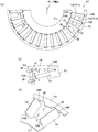
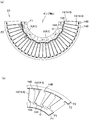
- FIG. 2A is a plan view of a single blade fixed blade assembly
- FIG. 2B is a plan view of a single blade fixed blade blade before bending a plurality of fixed blade blades.
- FIG. 2 (c) is a partial perspective image view of a single blade structure fixed blade blade assembly.
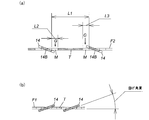
- 3 (a) is an AA cross-sectional development enlarged view in FIG. 2 (a)
- FIG. 3 (b) is a BB cross-sectional development enlarged view in FIG. 2 (a).
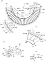
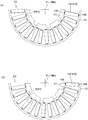
- FIG. 4A is a plan view of a fixed blade blade assembly having a two-ply structure
- FIG. 4A is a plan view of a fixed blade blade assembly having a two-ply structure
- FIG. 4B is a plan view showing a state before bending of a plurality of fixed blades in the fixed blade blade assembly having a two-ply structure.
- 4 (c) is a partial perspective image view of a fixed blade blade assembly having a two-layer structure
- FIG. 4 (d) is an explanatory view of caulking.
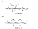
- 5A is an AA cross-sectional development enlarged view of the fixed blade blade assembly provided with the protrusions of FIG. 4A
- FIG. 5B is an AA cross-section when the protrusions of FIG. 4A are not provided. Expanded enlarged view.
- FIG. 5A is an AA cross-sectional development enlarged view of the fixed blade blade assembly provided with the protrusions of FIG. 4A
- FIG. 5B is an AA cross-section when the protrusions of FIG. 4A are not provided. Expanded enlarged view.
- FIG. 5A is an AA cross-sectional development enlarged view of the fixed blade blade assembly provided with the pro
- FIG. 6A shows a fixed blade having a double-layer structure in which an example of preventing internal leakage (back flow of gas molecules through the air gap) is adopted by shifting the fixed blade blade in the radial direction of the rotor (offset).
- FIG. 6B is a partial perspective image view of the fixed wing blade assembly.
- 7 (a) and 7 (b) are plan views of parts (a state after bending a plurality of fixed blades 14) before overlapping in the fixed blade blade assembly having a two-layer structure shown in FIG. 6 (a).
- FIG. 8A is an AA cross-sectional development enlarged view of a fixed blade blade assembly in which the fixed blade blades are shifted (offset) in the radial direction of the rotor as shown in FIG. 6A, and FIG.
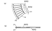
- FIG. 9A is an explanatory view of another specific structure example of the opening means
- FIG. 9B is a developed BB cross-sectional view in FIG. 9A
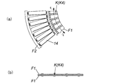
- FIG. 10A is an explanatory view of another specific structure example of the opening means
- FIG. 10B is a CC cross-sectional development enlarged view in FIG.
- FIG. 11A is an explanatory view of another specific structure example of the opening means
- FIG. 11B is an expanded view of the EE cross section in FIG. 11A
- 12A is an explanatory diagram of another specific structure example of the opening means
- FIG. 12B is a DD cross-sectional development enlarged view in FIG. 12A
- FIG. 13 is an explanatory diagram of another specific structure example of the opening means.
- FIG. 1 is a sectional view of an exhaust pump to which the present invention is applied.
- the exhaust pump P shown in the figure is used as a gas exhaust means for a process chamber and other sealed chambers in a semiconductor manufacturing apparatus, a flat panel display manufacturing apparatus, and a solar panel manufacturing apparatus.
- the exhaust pump P includes a blade exhaust part Pt that exhausts gas by the rotary blade 13 and the fixed blade 14, and a screw groove exhaust part Ps that exhausts gas by using the screw groove 19. These drive systems are included.
- the outer case 1 has a bottomed cylindrical shape in which a cylindrical pump case 1A and a bottomed cylindrical pump base 1B are integrally connected with bolts in the cylinder axis direction.
- the upper end portion side of the pump case 1A is opened as a gas intake port 2, and a gas exhaust port 3 is provided on the side surface of the lower end portion of the pump base 1B.
- the gas inlet 2 is connected to a sealed chamber (not shown), which is a high vacuum, such as a process chamber of a semiconductor manufacturing apparatus, by a bolt (not shown) provided on the flange 1C on the upper edge of the pump case 1A.
- the gas exhaust port 3 is connected so as to communicate with an auxiliary pump (not shown).
- a cylindrical stator column 4 containing various electrical components is provided in the center of the pump case 1A, and the stator column 4 is erected in such a manner that its lower end is screwed and fixed onto the pump base 1B. is there.
- a rotor shaft 5 is provided inside the stator column 4, and the rotor shaft 5 is arranged such that its upper end portion faces the gas inlet 2 and its lower end portion faces the pump base 1B. is there. Further, the upper end portion of the rotor shaft 5 is provided so as to protrude upward from the cylindrical upper end surface of the stator column 4.
- the rotor shaft 5 is levitated and supported by the magnetic force of the radial magnetic bearing 10 and the axial magnetic bearing 11 so that the radial direction and the axial direction can rotate, and is driven to rotate by the drive motor 12. Further, protective bearings B1 and B2 are provided on the upper and lower ends of the rotor shaft 5.
- a rotor 6 is provided outside the stator column 4.
- the rotor 6 has a cylindrical shape surrounding the outer periphery of the stator column 4 and is integrated with the rotor shaft 5. Therefore, in the exhaust pump P of FIG. 1, the rotor shaft 5, the radial magnetic bearings 10, 10 and the axial magnetic bearing 11 function as support means for rotatably supporting the rotor 6 about its axis. Further, since the rotor 6 rotates integrally with the rotor shaft 5, the drive motor 12 that rotationally drives the rotor shaft 5 functions as a drive unit that rotationally drives the rotor 6.
- a plurality of rotor blades 13 are integrally provided on the outer circumferential surface of the rotor 6 on the upstream side of the middle of the rotor 6.
- the plurality of rotor blades 13 protrude from the outer peripheral surface of the rotor 6 in the radial direction of the rotor, and the rotation axis of the rotor 6 (rotor shaft 5) or the axis of the outer case 1 (hereinafter referred to as “pump”). It is arranged in a radial pattern centering on the axis.
- the rotor blade 13 is a cut product that is cut and formed integrally with the outer diameter processing portion of the rotor 6 and is inclined at an optimum angle for exhausting gas molecules.
- a plurality of fixed blades 14 are provided on the inner peripheral surface side of the pump case 1A, and these fixed blades 14 project from the inner peripheral surface of the pump case 1A toward the outer peripheral surface of the rotor 6. And it arrange
- the fixed blade 14 is also inclined at an optimum angle for exhausting gas molecules, like the rotary blade 13.
- the plurality of blade blades 13 and the stationary blade blades 14 are alternately arranged in multiple stages along the pump axis so that the multistage blade exhaust part Pt is formed. Forming.
- a plurality of fixed blades 14 positioned at least in one stage are formed as a single blade fixed blade assembly S1 shown in FIG.
- the plurality of fixed blades 14 positioned in at least one stage are formed as a fixed blade blade assembly S2 having a two-layer structure shown in FIG. 4 for each stage.
- the plurality of fixed blades 14 positioned at least in one stage are formed as the single blade structure fixed blade blade assembly S1, and the other plurality of fixed blades 14 positioned in at least one stage are fixed in the two-layer structure.
- the blade blade assembly S2 is formed.
- the detailed configuration of each fixed blade assembly S1, S2 is as follows.
- the single-blade fixed blade assembly S1 includes a plurality of fixed blades 14 arranged radially about the pump axis as described above, and these fixed blades. Frames F1 and F2 that respectively support the fixed blade blade bases 14A and 14B on the inner side and the outer side of the blade 14 are provided.
- this single blade fixed blade assembly S1 for example, one fixed blade 14 (14-1) and the adjacent fixed blade 14 (14-2) adjacent to each other are fixed inside and outside.
- the blade blade roots 14A and 14B are supported by the same frames F1 and F2.
- the plurality of fixed blades 14 positioned at least in one stage have the inner and outer fixed blade bases 14A and 14B at the frame F1, for each stage. Supported by F2. And, between the supported fixed blade 14 (for example, 14-1) and the adjacent adjacent fixed blade 14 (for example, 14-2), the outer and inner fixed blade blade roots 14A, In the gap in the vicinity of 14B, a projection T projecting from the frame F2 supporting the outer fixed blade blade root 14B, and a projection T projecting from the frame F1 supporting the inner fixed blade blade base 14A. Is provided. Any one of these protrusions T may be omitted as necessary.
- the protrusion T functions as a means for preventing the backflow (internal leakage) of gas molecules passing through the gap G in the vicinity of the fixed blade blade bases 14A and 14B.
- the groove M is notched and formed in the vicinity of the fixed blade blade roots 14A and 14B. 14 is bent up.
- the above-described gap G is generated in the vicinity of the fixed blade blade roots 14A and 14B by the groove M (hereinafter referred to as “bending groove M”) indispensable for the bending raising process.
- the protrusion T is arranged in such a gap G, the backflow (internal leakage) of gas molecules passing through the gap G is reduced, the exhaust speed is increased, and the exhaust time is shortened. I can plan.
- FIG. 2 (b) is a plan view showing a state before bending a plurality of fixed blades in the single blade fixed blade assembly S1.
- the symbol “a” is the width of the bending groove M
- the symbol “b” is the width of the fixed blade blade base 14A that is narrowed by the formation of the bending groove M
- the symbol “c” is the protrusion of the protrusion T.
- the quantity and symbol “d” indicate the width of the gap G between the protrusion T and the fixed blade 14.
- the “a” and “b” are determined by conditions such as the material, thickness, and inclination (bending) angle (see FIG. 3B) of the fixed blade 14.
- the “c” can be appropriately changed as necessary. In particular, when the condition that “c” is equal to or greater than “a” (c ⁇ a) is satisfied, the above-described backflow (internal leak) reduction effect is improved.
- “d” varies depending on the means (wire processing, laser processing, press processing, etc.) for forming the fixed blade blade assembly S1, but is set to the minimum as possible from the viewpoint of reducing the backflow of gas molecules. Is preferred.
- FIG. 3 (a) is an AA sectional development enlarged view in FIG. 2 (a).
- the symbol L1 indicates the width of the gap near the bending groove when there is no projection T
- the symbols L2 and L3 indicate the width of the gap G near the bending groove M that is narrowed by the formation of the projection T.
- the width of the gap G with the protrusion T decreases to 30% or less ((L2 + L3) / L1 * 100 ⁇ 30%). For this reason, according to the same example, the effect of reducing the backflow (internal leakage) of gas molecules passing through the gap G by 70% or more can be obtained.
- the fixed blade blade assembly S2 having a two-ply structure also includes a plurality of fixed blades 14 arranged radially around the pump axis as described above, and these fixed blades.
- Frames F1 and F2 that respectively support the fixed blade blade bases 14A and 14B on the inner side and the outer side of the blade 14 are provided.
- each fixed blade 14 (14-3) and its adjacent blade 14 (14-4) are arranged as shown in FIG. 4C.
- Each of the inner fixed blade blade bases 14A is supported by a separate frame F1, and the frames F1 are vertically stacked and joined.
- Each outer fixed blade blade base 14B is also supported by a separate frame F2, and has a structure in which these frames F2 are vertically stacked and joined.
- FIG. 4A as a specific structural example of the joining of the frames F1 and F2, the frames F1 supporting the fixed blade blade bases 14A on the inner side are as shown in FIG. A structure that is joined by caulking is adopted.
- the exhaust pump P adopting the above-described joining configuration, it is possible to suppress the phenomenon that the frame F1 that is vertically stacked opens upward and downward due to warpage, bending, and the like, and this phenomenon causes the height of the fixed blade blade to increase. Therefore, it is possible to effectively prevent the deterioration of exhaust performance due to the non-uniformity.
- the joining of the frames F1 as described above is not limited to the caulking process as shown in FIG. 4 (d) described above.
- a method other than the caulking process such as adhesion using an adhesive or welding is adopted. You can also.
- the plurality of fixed blades positioned at least in one stage have the inner and outer fixed blade blade bases 14A and 14B in the frames F1 and F2 for each stage. It is supported by. Between the one fixed blade 14 (for example, 14-3) that is supported and the adjacent fixed blade 14 (for example, 14-4), as shown in FIG. A protrusion T protruding from the frame F2 supporting the blade blade root 14B is provided.
- the protrusion T is formed so as to overlap with the gap G near the fixed blade blade root 14B, thereby functioning as a means for preventing the backflow (internal leakage) of gas molecules passing through the gap G.
- a protrusion T may be formed so as to protrude from the frame F1 supporting the inner fixed blade blade root 14A, or formed so as to protrude from both the frames F1, F2. You can also
- FIG. 4B is a plan view of a part S2 ′ (a state before the plurality of fixed blades 14 are bent) before the overlapping in the two-layered fixed blade assembly S2 of FIG. is there.
- the fixed blade blade assembly S2 having a two-layer structure shown in FIG. 4 (a) two parts S2 ′ shown in FIG. 4 (b) are produced (two are exactly the same), and one is turned over. It is the one that is overlapped and joined to the other.
- the symbol “a” is the width of the bending groove M
- the symbol “b” is the width of the base 14B of the fixed wing blade that has become thin by forming the bending groove M
- the symbols “c” and “e” are protrusions.
- the protruding amount of the portion T, the symbol “d”, indicates the width of the gap G (the gap near the fixed blade blade root 14B) between the protrusion T and the fixed blade blade 14.
- the “a” and “b” are determined by conditions such as the material, thickness, and inclination (bending) angle (see FIG. 3B) of the fixed blade 14.
- the “c” may be appropriately changed as necessary. In particular, when the condition that “c” is equal to or greater than “a” (c ⁇ a) is satisfied, the above-described backflow (internal leak) reduction effect is improved.
- “d” varies depending on the means for forming the part S2 ′ (wire processing, laser processing, press processing, etc.), the viewpoint of reducing the back flow of gas molecules after the parts S2 ′ are overlapped and joined. Therefore, “d” is preferably set to the minimum possible.
- the “e” is set smaller than the “a” (e ⁇ a). This is because the tip of the fixed wing blade 14 that is bent is placed on the protrusion T having the “e” size, so that interference between the protrusion T having the “e” size and the tip of the fixed wing blade 14 is avoided. It is.
- the angles ⁇ and ⁇ are also set so as not to interfere.
- FIG. 5A is an AA cross-sectional development enlarged view of the fixed blade blade assembly S2 provided with the projection T as shown in FIG. 4A
- FIG. 5B is a projection T of FIG. 4A. It is an AA cross-section expansion enlarged view when there was not (Comparative example with FIG. 5A).
- reference numerals L4 and L5 indicate the width of the gap G near the bending groove M when there is no protrusion T, and reference numerals L6 and L7 become narrow due to the formation of the protrusion T.
- the width of the gap G near the bent groove M is shown. Comparing with and without the protrusion T, the width of the gap G with the protrusion T decreases to 10% or less ((L6 + L7) / (L4 + L5) * 100 ⁇ 10%). For this reason, according to the same example, by providing the protrusion T, an effect of reducing the backflow (internal leakage) of gas molecules passing through the gap G near the bending groove M by 90% or more can be obtained.
- FIG. 6A shows a fixed blade having a double-layer structure in which an example of preventing internal leakage (back flow of gas molecules through the air gap) is adopted by shifting the fixed blade blade in the radial direction of the rotor (offset).
- FIG. 6B is a partial perspective image view of the fixed blade blade assembly.
- FIG. 7 (a) and 7 (b) show the part S3 ′ (the state after bending a plurality of fixed blades 14) before the overlapping in the two-layered fixed blade assembly S3 of FIG. It is a top view.
- the part S3 'in FIG. 7 (b) is an inverted version of the part S3' in FIG. 7 (a), and the fixed blade blade assembly S3 having a two-layer structure shown in FIGS.
- the parts S3 'in FIGS. 7 (a) and 7 (b) are superposed and joined.
- the fixed blade blade assembly S3 having a two-layer structure shown in FIGS. 6 (a) and 6 (b), for example, one fixed blade 14 (14-5) and the adjacent one of the plurality of fixed blades 14 constituting the fixed blade blade assembly S3.
- the fixed blade 14 (14-6) as shown in FIGS. 7A and 7B, the fixed blade blade bases 14A and 14B are supported by separate frames F1 and F2, respectively. It has a structure in which the top and bottom are joined.
- one fixed blade 14 (14-5) and the adjacent adjacent fixed blade 14 (14-6) have a fixed blade base 14A on the inside.
- the fixed blade edge at the base of the fixed blade blade 14A inside the fixed blade 14 (14-5) is fixed next to it.
- the wing blade 14 (14-6) is configured to overlap with the gap G in the vicinity of the base 14A of the fixed wing blade.
- the backflow of the gas molecules passing through the gap G is suppressed by the fixed blade end in the vicinity of the fixed blade root 14A inside the single fixed blade (14-5). Also in the exhaust pump P employing the fixed blade blade assembly S3 having the two-layer structure b), the exhaust speed is increased and the exhaust performance can be improved by shortening the exhaust time.
- FIG. 8A is an enlarged AA cross-sectional view of the fixed blade blade assembly S3 in which the fixed blade blades 14 are shifted (displaced) in the radial direction of the rotor 6 as shown in FIGS. 6A and 6B.
- 8 (b) is an AA cross-sectional development enlarged view when such offset is not performed (comparative example with FIG. 8 (a)).
- reference numerals L8, L9, and L10 indicate the width of the gap near the bending groove M when no offset is performed
- reference numeral L11 indicates the vicinity of the bending groove M that is narrowed by the offset.
- the width of the gap is shown. Comparing with and without offset, the gap width when offset is reduced to 30% or less ((L11) / (L8 + L9 + L10) * 100 ⁇ 30%). For this reason, according to the same example, the effect of reducing the backflow (internal leakage) of the gas molecules passing through the voids by 70% or more can be obtained by offsetting.
- the overlapping portion of the inner frame F1 has a gas trapped in the overlapping portion.
- An opening means K for allowing the fluid to escape out of the frame F1 is provided.
- a notch K1 is formed at the inner edge of the inner frame F1.
- the contact area of the overlapping surface of the frame F1 is smaller in the present example where the notch K1 is provided.
- the amount of gas or fluid confined in the part is smaller.
- gas or fluid is somewhat enclosed in the overlapping portion of the frame F1 in the portion without the cutout K1, but the closed gas can quickly flow out of the frame F1 from the cutout of the cutout K1. . Therefore, according to the exhaust pump P employing the notch K1 as in the examples of FIGS. 4A and 6A, the amount of gas and fluid that continues to flow out gradually from the overlapping portion of the frame F1. This reduces the exhaust time.
- opening means K include, for example, a hole K2 formed in the inner frame F1 as shown in FIGS. 9 (a) and 9 (b), and a frame as shown in FIGS. 10 (a) and 10 (b).
- a recess K5 formed by cutting or pressing in F1 or a combination of the notch K1, hole K2, open grooves K3, K4, and recess K5 may be employed.
- 9A and 9B exemplify a substantially rectangular hole as an example of the hole K2, it is not limited to the shape of the hole, and holes of various shapes can be employed. The same applies to the notch K1 in FIGS. 4A and 6A and the recess K5 in FIGS. 12A and 12B.
- the open grooves K3 and K4 include radial grooves provided around the pump axis, and although it has a communication groove communicating with these radiating grooves and one end of the radiating groove is opened outside the overlapping portion of the frame F1, the present invention is not limited to this form.
- various forms of open grooves K6 to K10 opened outside the overlapping portion of the frame F1 can be employed.
- the opening means described above may adopt a configuration provided in the overlapping portion of the outer frame F2 or a configuration provided in both the inner and outer frames F1 and F2, as necessary.
- the gas molecules on the gas inlet 2 side are exhausted so as to sequentially move toward the downstream of the rotor 6.
- the protrusion T arranged so as to overlap the gap G near the end of the fixed blade 14 prevents the backflow (internal leakage) of gas molecules passing through the gap G, so that the exhaust speed is increased.
- the exhaust time can be shortened.
Landscapes
- Engineering & Computer Science (AREA)
- Mechanical Engineering (AREA)
- General Engineering & Computer Science (AREA)
- Non-Positive Displacement Air Blowers (AREA)
- Structures Of Non-Positive Displacement Pumps (AREA)
Abstract
【課題】排気時間の短縮による排気性能の向上を図るのに好適な固定翼ブレード集合体、及びそれを備えた排気ポンプを提供する。 【解決手段】複数の固定翼ブレード14は、内側と外側の固定翼ブレード根元14A、14BがフレームF1、F2で支持されており、この支持された一の固定翼ブレード14(14-1)とその横隣の固定翼ブレード14(14-2)との間であって、かつ外側又は内側の固定翼ブレード根元14A、14B付近の空隙には、内側の固定翼ブレード根元14Aを支持しているフレームF1又は外側の固定翼ブレード根元14Bを支持しているフレームF2若しくは双方のフレームF1、F2から突出した突起部Tが設けられる。
Description
本発明は、半導体製造装置、フラット・パネル・ディスプレイ製造装置、ソーラー・パネル製造装置におけるプロセスチャンバ、その他の密閉チャンバのガス排気手段等として利用される排気ポンプに適用可能な固定翼ブレード集合体、及びそれを備えた排気ポンプに関し、特に、その排気時間の短縮による排気性能の向上を図れるようにしたものである。
従来、この種の排気ポンプとしては、例えば特許文献1に記載の真空ポンプが知られている。同文献1の真空ポンプは、同文献1の図13に示されているように、回転可能なロータ(2)の外周面から突出した複数の回転翼ブレード(9)と、ロータ(2)の外周面に向って突出した複数の固定翼ブレード(10)とを、ロータ(2)の軸心に沿って交互に多段に配置した構造になっている。
また、同文献1の図3及び図4を参照すると、前記各段のうちいずれか一段に位置する複数の固定翼ブレード(10)は、その段ごとに、内側と外側のブレード根元がフレーム(10-1、10-2)で支持される構造になっている。
しかしながら、先に例示した特許文献1の真空ポンプにあっては、同文献1の図1に示されているように固定翼ブレード(10)を所定角度で傾斜させるため、そのブレード根元付近に溝(102-2、102-3)を切り欠き形成して固定翼ブレード(10)を曲げ起こしている。このため、そのような曲げ起し加工に必要不可欠な前記溝(102-2、102-3)により固定翼ブレード(10)のブレード根元付近に空隙が生じることは避けられず、かかる空隙を抜けて気体分子が逆流する(内部リーク)ため、排気開始から所望の真空度に到達するまでの時間(以下「排気時間」という)が長くならざるを得ないという問題点がある。
特許文献2の図4(b)を参照すると、同文献2の真空ポンプでは、先に説明した各段に位置する複数の固定翼ブレード(21)の具体的な構成として、一の固定翼ブレード(21(A))とその横隣の固定翼ブレード(21(C))は、それぞれのブレード根元が別々のフレーム(23)で支持され(同文献の図4(a)を参照)、これらのフレーム(23)を上下に重ね合わせることにより二枚重ね構造の固定翼ブレード集合体として形成している。
しかしながら、特許文献2のような二枚重ね構造の固定翼ブレード集合体では、上下に重ね合わせたフレーム(23)が反りや撓み等によって上下方向に開いてしまうおそれがあり、そのようにフレーム(23)が開くことにより、固定翼ブレード(23)の高さが不均一になり、不均一による排気効率の低下で排気時間が長くなるという問題点がある。
また、特許文献2のような二枚重ね構造の固定翼ブレード集合体では、フレーム(23)を上下に重ね合わせているので、上下に重ね合わせたフレーム(23)間に気体や流体が閉じ込まれるおそれがあり、そのように閉じ込まれた気体や流体が排気動作時にフレーム(23)の重ね合せ部から少しずつ徐々に流出し続けるため、この点でも排気時間が長くなるという問題点がある。
本発明は、前記問題点を解決するためになされたものであり、その目的は、排気時間の短縮による排気性能の向上を図るのに好適な固定翼ブレード集合体、及びそれを備えた排気ポンプを提供することにある。
前記目的を達成するために、第1の本発明は、回転可能なロータの外周面から突出した複数の回転翼ブレードと、前記ロータの外周面に向って突出した複数の固定翼ブレードとを、前記ロータの軸心に沿って交互に多段に配置してなる排気ポンプに適用可能な固定翼ブレード集合体であって、前記複数の固定翼ブレードは、内側と外側の固定翼ブレード根元がフレームで支持されており、この支持された一の固定翼ブレードとその横隣の固定翼ブレードとの間であって、かつ前記外側又は内側の固定翼ブレード根元付近の空隙には、内側の固定翼ブレード根元を支持しているフレーム又は前記外側の固定翼ブレード根元を支持しているフレーム若しくは双方のフレームから突出した突起部が設けられた構成になっていることを特徴とする。
前記第1の本発明において、一の固定翼ブレードとその横隣の固定翼ブレードは、それぞれの内側及び外側の固定翼ブレード根元が同じフレームで支持されることにより、一枚構造の固定翼ブレード集合体として構成されるものであってもよい。
前記第1の本発明において、前記一の固定翼ブレードとその横隣の固定翼ブレードは、それぞれの内側及び外側の固定翼ブレード根元が別々のフレームで支持され、これらのフレームを上下に重ね合わせて接合することにより二枚重ね構造として形成され、前記突起部が前記外側又は内側の固定翼ブレード根元付近の空隙と重なる構成となっていることを特徴とする。
第2の本発明は、回転可能なロータの外周面から突出した複数の回転翼ブレードと、前記ロータの外周面に向って突出した複数の固定翼ブレードとを、前記ロータの軸心に沿って交互に多段に配置してなる排気ポンプに適用可能な固定翼ブレード集合体であって、前記複数の固定翼ブレードのうちいずれか一の固定翼ブレードとその横隣の固定翼ブレードは、それぞれの固定翼ブレード根元が別々のフレームで支持され、これらのフレームを上下に重ね合わせて接合することにより一枚の固定翼ブレード集合体として形成される構成、及び、それぞれの固定翼ブレード根元が互いにロータの径方向でずれて配置されることにより、一の固定翼ブレード根元付近における固定翼ブレード端部がその横隣の固定翼ブレード根元付近の空隙に重なる構成になっていることを特徴とする。
第3の本発明は、回転可能なロータの外周面から突出した複数の回転翼ブレードと、前記ロータの外周面に向って突出した複数の固定翼ブレードとを、前記ロータの軸心に沿って交互に多段に配置してなる排気ポンプに適用可能な固定翼ブレード集合体であって、前記複数の固定翼ブレードのうちいずれか一の固定翼ブレードとその横隣の固定翼ブレードは、それぞれの固定翼ブレード根元が別々のフレームで支持され、これらのフレームを上下に重ね合わせてなるとともに、それぞれの外側又は内側の固定翼ブレード根元を支持している前記フレームどうしを接合することにより一枚の固定翼ブレード集合体として形成されていることを特徴とする。
前記第3の本発明において、フレームの重ね合わせ部には、その重ね合わせ部に閉じ込まれている気体や流体をフレームの外へ逃がす開放手段が設けられる構成を採用することができる。
前記第3の本発明において、開放手段は、前記フレームに形成した切り欠きからなることを特徴とする。
前記第3の本発明において、開放手段は、前記フレームに形成した穴からなることを特徴とする。
前記第3の本発明において、開放手段は、前記フレームに形成した開放溝からなることを特徴とする。
前記第3の本発明において、開放手段は、前記フレームに形成した窪みからなることを特徴とする。
前記第3の本発明において、前記フレームどうしの接合は、カシメ加工によるものであってもよい。
本発明に係る排気ポンプは、前記第1から第3の本発明に係る固定翼ブレード集合体のいずれかを備えたことを特徴とするものである。
前記第1の本発明にあっては、排気ポンプに適用可能な固定翼ブレード集合体の具体的な構成として、複数の固定翼ブレードは、内側と外側の固定翼ブレード根元がフレームで支持されており、この支持された一の固定翼ブレードとその横隣の固定翼ブレードとの間であって、かつ前記外側又は内側の固定翼ブレード根元付近の空隙には、内側の固定翼ブレード根元を支持しているフレーム又は前記外側の固定翼ブレード根元を支持しているフレーム若しくは双方のフレームから突出した突起部が設けられた構成を採用した。このため、そのような固定翼ブレード根元付近の空隙を抜ける気体分子の逆流(内部リーク)が当該突起部により抑制されることから、高速で排気でき、排気時間の短縮を図れる。
前記第2の本発明では、排気ポンプに適用可能な固定翼ブレード集合体の具体的な構成として、複数の固定翼ブレードのうちいずれか一の固定翼ブレードとその横隣の固定翼ブレードは、それぞれの固定翼ブレード根元が別々のフレームで支持され、これらのフレームを上下に重ね合わせて接合することにより一枚の固定翼ブレード集合体として形成される構成、及び、それぞれの固定翼ブレード根元が互いにロータの径方向でずれて配置されることにより、一の固定翼ブレード根元付近における固定翼ブレード端部がその横隣の固定翼ブレード根元付近の空隙に重なる構成を採用した。このため、本第2の発明でも、かかる空隙を抜ける気体分子の逆流がその空隙に重なっているブレード根元付近の固定翼ブレード端部で抑制されるから、高速で排気でき、排気時間の短縮を図れる。
前記第3の本発明によると、排気ポンプに適用可能な固定翼ブレード集合体の具体的な構成として、複数の固定翼ブレードのうちいずれか一の固定翼ブレードとその横隣の固定翼ブレードは、それぞれの固定翼ブレード根元が別々のフレームで支持され、これらのフレームを上下に重ね合わせてなるとともに、それぞれの外側又は内側の固定翼ブレード根元を支持している前記フレームどうしを接合することにより一枚の固定翼ブレード集合体として形成されている構成を採用した。このため、外側又は内側の固定翼ブレード根元付近において、上下に重ね合わされたフレームが反りや撓み等により上下方向に開いてしまうことがなく、そのようなフレームの開きによって固定翼ブレードの高さが不均一になることや、その不均一による排気効率の低下を効果的に防止できる点で、排気時間の短縮を図れる。
特に、前記第3の本発明において、フレームの重ね合わせ部に閉じ込まれている気体や流体をフレームの外へ逃がす開放手段が設けられる構成を採用したものにあっては、フレームの重ね合せ部に閉じ込まれている気体や流体は開放手段によって速やかにフレームの外へ開放されるから、そのような気体や流体がフレームの重ね合せ部から少しずつ徐々に流出し続けることがなくなる点で、排気時間の更なる短縮を図れる。
以下、本発明を実施するための最良の形態について、添付した図面を参照しながら詳細に説明する。
図1は、本発明を適用した排気ポンプの断面図である。同図の排気ポンプPは、半導体製造装置、フラット・パネル・ディスプレイ製造装置、ソーラー・パネル製造装置におけるプロセスチャンバやその他の密閉チャンバのガス排気手段等として利用される。この排気ポンプPは、外装ケース1内に、回転翼ブレード13と固定翼ブレード14により気体を排気する翼排気部Ptと、ネジ溝19を利用して気体を排気するネジ溝排気部Psと、これらの駆動系とを有している。
外装ケース1は、筒状のポンプケース1Aと有底筒状のポンプベース1Bとをその筒軸方向にボルトで一体に連結した有底円筒形になっている。ポンプケース1Aの上端部側はガス吸気口2として開口しており、ポンプベース1Bの下端部側面にはガス排気口3を設けてある。
ガス吸気口2は、ポンプケース1A上縁のフランジ1Cに設けた図示しないボルトにより、例えば半導体製造装置のプロセスチャンバ等、高真空となる図示しない密閉チャンバに接続される。ガス排気口3は、図示しない補助ポンプに連通するように接続される。
ポンプケース1A内の中央部には各種電装品を内蔵する円筒状のステータコラム4が設けられており、ステータコラム4はその下端側がポンプベース1B上にネジ止め固定される形態で立設してある。
ステータコラム4の内側にはロータ軸5が設けられており、ロータ軸5は、その上端部がガス吸気口2の方向を向き、その下端部がポンプベース1Bの方向を向くように配置してある。また、ロータ軸5の上端部はステータコラム4の円筒上端面から上方に突出するように設けてある。
ロータ軸5は、ラジアル磁気軸受10とアキシャル磁気軸受11の磁力で径方向と軸方向が回転可能に浮上支持され、駆動モータ12により回転駆動される。また、このロータ軸5の上下端側には保護ベアリングB1、B2を設けている。
ステータコラム4の外側にはロータ6が設けられている。ロータ6は、ステータコラム4の外周を囲む円筒形状であって、ロータ軸5に一体化されている。従って、図1の排気ポンプPでは、ロータ軸5、ラジアル磁気軸受10、10及びアキシャル磁気軸受11が、ロータ6をその軸心周りに回転可能に支持する支持手段として機能する。またロータ6はロータ軸5と一体に回転するので、ロータ軸5を回転駆動する駆動モータ12がロータ6を回転駆動する駆動手段として機能する。
駆動モータ12、保護ベアリングB1とB2、ラジアル磁気軸受10及びアキシャル磁気軸受11の詳細構成については業界周知の内容のため、説明を省略する。
《翼排気部Ptの詳細構成》
図1の排気ポンプPでは、ロータ6の略中間より上流(ロータ6の略中間からロータ6のガス吸気口2側端部までの範囲)が翼排気部Ptとして機能する。以下この翼排気部Ptを詳細に説明する。
図1の排気ポンプPでは、ロータ6の略中間より上流(ロータ6の略中間からロータ6のガス吸気口2側端部までの範囲)が翼排気部Ptとして機能する。以下この翼排気部Ptを詳細に説明する。
ロータ6の略中間より上流側のロータ6外周面には回転翼ブレード13が一体に複数設けられている。これら複数の回転翼ブレード13は、ロータ6外周面からロータ径方向に突出した形態になっていて、かつ、ロータ6の回転軸心(ロータ軸5)若しくは外装ケース1の軸心(以下「ポンプ軸心」という)を中心として放射状に配置してある。また、回転翼ブレード13は、ロータ6の外径加工部と一体的に切削加工で切り出し形成した切削加工品であって、気体分子の排気に最適な角度で傾斜している。
ポンプケース1Aの内周面側には固定翼ブレード14が複数設けられており、これらの固定翼ブレード14は、ポンプケース1A内周面からロータ6外周面に向って突出した形態になっていて、かつ、ポンプ軸心を中心として放射状に配置してある(図2及び図4参照)。固定翼ブレード14もまた、回転翼ブレード13と同じく、気体分子の排気に最適な角度で傾斜している。
そして、図1の排気ポンプPにおいては、前記のような複数の回転翼ブレード13と固定翼ブレード14とがポンプ軸心に沿って交互に多段に配置されることによって多段の翼排気部Ptを形成している。
前記多段の翼排気部Ptにおいて、少なくとも一段に位置する複数の固定翼ブレード14は、その段ごとに、図2に示す一枚構造の固定翼ブレード集合体S1として形成してある。或は、少なくとも一段に位置する複数の固定翼ブレード14は、その段ごとに、図4に示す二枚重ね構造の固定翼ブレード集合体S2として形成してある。又は、少なくとも一段に位置する複数の固定翼ブレード14は、前記一枚構造の固定翼ブレード集合体S1として形成し、他の少なくとも一段に位置する複数の固定翼ブレード14は、前記二枚重ね構造の固定翼ブレード集合体S2として形成してある。それぞれの固定翼ブレード集合体S1、S2の詳細構成は以下の通りである。
《一枚構造の固定翼ブレード集合体S1の詳細構成》
図2(a)を参照すると、一枚構造の固定翼ブレード集合体S1は、先に説明したようにポンプ軸心を中心として放射状に配置される複数の固定翼ブレード14と、これらの固定翼ブレード14の内側と外側の固定翼ブレード根元14A、14Bをそれぞれ支持するフレームF1、F2とを備えている。そして、この一枚構造の固定翼ブレード集合体S1では、例えば一の固定翼ブレード14(14-1)とその横隣の固定翼ブレード14(14-2)は、それぞれの内側及び外側の固定翼ブレード根元14A、14Bが同じフレームF1、F2で支持される構造になっている。
図2(a)を参照すると、一枚構造の固定翼ブレード集合体S1は、先に説明したようにポンプ軸心を中心として放射状に配置される複数の固定翼ブレード14と、これらの固定翼ブレード14の内側と外側の固定翼ブレード根元14A、14Bをそれぞれ支持するフレームF1、F2とを備えている。そして、この一枚構造の固定翼ブレード集合体S1では、例えば一の固定翼ブレード14(14-1)とその横隣の固定翼ブレード14(14-2)は、それぞれの内側及び外側の固定翼ブレード根元14A、14Bが同じフレームF1、F2で支持される構造になっている。
以上の支持構造から分かるように、多段の翼排気部Ptにおいて、少なくとも一段に位置する複数の固定翼ブレード14は、その段ごとに、内側と外側の固定翼ブレード根元14A、14BがフレームF1、F2で支持されている。そして、支持された一の固定翼ブレード14(例えば14-1)とその横隣の固定翼ブレード14(例えば14-2)との間であって、かつ外側と内側の固定翼ブレード根元14A、14B付近の空隙には、外側の固定翼ブレード根元14Bを支持しているフレームF2から突出した突起部T、及び、内側の固定翼ブレード根元14Aを支持しているフレームF1から突出した突起部Tを設けている。これらの突起部Tについては、必要に応じていずれか一方を省略してもよい。
前記突起部Tは、固定翼ブレード根元14A、14B付近の空隙Gを抜ける気体分子の逆流(内部リーク)を防止する手段として機能する。
すなわち、図1の排気ポンプPにおいては、先に説明したように固定翼ブレード14を所定角度で傾斜させるために、固定翼ブレード根元14A、14B付近に溝Mを切り欠き形成して固定翼ブレード14を曲げ起こしている。このような曲げ起し加工に必要不可欠な前記溝M(以下「曲げ溝M」という)により固定翼ブレード根元14A、14B付近に前述の空隙Gが生じる。図1の排気ポンプPでは、そのような空隙Gに突起部Tが配置されるため、空隙Gを抜ける気体分子の逆流(内部リーク)が減少し、排気速度が速くなり、排気時間の短縮を図れる。
図2(b)は、一枚構造の固定翼ブレード集合体S1において、複数の固定翼ブレードを曲げ起こす前の状態の平面図である。
図2(b)において、符号“a”は曲げ溝Mの幅、符号“b”は曲げ溝Mの形成により細くなった固定翼ブレード根元14Aの幅、符号“c”は突起部Tの突出量、符号“d”は突起部Tと固定翼ブレード14との間の隙間Gの幅を示している。
前記“a”と“b”については、固定翼ブレード14の材質、厚み、傾斜(曲げ)角度(図3(b)参照)などの条件によって決まる。前記“c”は、必要に応じて適宜変更できる。特に“c”は“a”と等しい又は“a”より大きいという条件(c≧a)が成立する場合に、上述の逆流(内部リーク)減少効果が向上する。また、前記“d”は、固定翼ブレード集合体S1を形成する手段(ワイヤ加工、レーザ加工、又はプレス加工等)によって異なるが、気体分子の逆流を減少させる観点より出来る限り最小に設定するのが好ましい。
図3(a)は、図2(a)中のAA断面展開拡大図である。この図3(a)において、符号L1は突起部Tが無い場合における曲げ溝付近の空隙の幅、符号L2とL3は突起部Tの形成により狭くなった曲げ溝M付近の空隙Gの幅を示している。突起部Tが有る場合と無い場合とで比較すると、突起部Tがある場合の空隙Gの幅は30%以下((L2+L3)/L1*100<30%)に減少する。このため、同例によると、空隙Gを抜ける気体分子の逆流(内部リーク)を70%以上減少させる効果が得られる。
《二枚重ね構造の固定翼ブレード集合体S2の詳細構成》
図4(a)を参照すると、二枚重ね構造の固定翼ブレード集合体S2もまた、先に説明したようにポンプ軸心を中心として放射状に配置される複数の固定翼ブレード14と、これらの固定翼ブレード14の内側と外側の固定翼ブレード根元14A、14Bをそれぞれ支持するフレームF1、F2とを備えている。
図4(a)を参照すると、二枚重ね構造の固定翼ブレード集合体S2もまた、先に説明したようにポンプ軸心を中心として放射状に配置される複数の固定翼ブレード14と、これらの固定翼ブレード14の内側と外側の固定翼ブレード根元14A、14Bをそれぞれ支持するフレームF1、F2とを備えている。
そして、この二枚重ね構造の固定翼ブレード集合体S2では、例えば一の固定翼ブレード14(14-3)とその横隣の固定翼ブレード14(14-4)は、図4(c)のように、それぞれの内側の固定翼ブレード根元14Aが別々のフレームF1で支持され、これらのフレームF1を上下に重ね合わせて接合した構造になっている。また、それぞれの外側の固定翼ブレード根元14Bも別々のフレームF2で支持され、これらのフレームF2を上下に重ね合わせて接合した構造になっている。
図4(a)の例では、前記フレームF1、F2の具体的な接合の構造例として、それぞれの内側の固定翼ブレード根元14Aを支持しているフレームF1どうしを図4(d)のようなカシメ加工によって接合する構成を採用した。
前記のような接合構成を採用した排気ポンプPによると、上下に重ね合わされたフレームF1が反りや撓み等によって上下方向に開いてしまう現象を抑制することができ、かかる現象によって固定翼ブレードの高さが不均一になること、及び、その不均一による排気性能の低下を効果的に防止することができる。かかる現象の抑制効果を高めるには、図4(a)のようにカシメ部をフレームF1の内端近傍に設けることが好ましい。
前記のようなフレームF1どうしの接合は先に説明した図4(d)のようなカシメ加工に限定されることはなく、例えば接着剤による接着や溶接等、カシメ加工以外の方式を採用することもできる。
以上の支持構造から分かるように、多段の翼排気部Ptにおいて、少なくとも一段に位置する複数の固定翼ブレードは、その段ごとに、内側と外側の固定翼ブレード根元14A、14BがフレームF1、F2で支持されている。そして、支持された一の固定翼ブレード14(例えば14-3)とその横隣の固定翼ブレード14(例えば14-4)との間には、図4(c)のように、外側の固定翼ブレード根元14Bを支持しているフレームF2から突出した突起部Tが設けられている。
この突起部Tは、固定翼ブレード根元14B付近の空隙Gと重なるように形成されることにより、その空隙Gを抜ける気体分子の逆流(内部リーク)を防止する手段として機能する。図示は省略するが、このような突起部Tは内側の固定翼ブレード根元14Aを支持しているフレームF1から突出するように形成してもよく、双方のフレームF1、F2から突出するように形成することもできる。
図4(b)は、同図(a)の二枚重ね構造の固定翼ブレード集合体S2において、その重ね合わせ前のパーツS2′(複数の固定翼ブレード14を曲げ起こす前の状態)の平面図である。図4(a)の2枚重ね構造の固定翼ブレード集合体S2は、この図4(b)のパーツS2′を2枚作製し(2枚は全く同一のもの)、一枚を裏返しにしてもう一枚に重ね合わせて接合したものである。
図4(b)において、符号“a”は曲げ溝Mの幅、符号“b”は曲げ溝Mの形成により細くなった固定翼ブレード根元14Bの幅、符号“c”と“e”は突起部Tの突出量、符号“d”は突起部Tと固定翼ブレード14との間の空隙G(固定翼ブレード根元14B付近の空隙)の幅を示している。
前記“a”と“b”については、固定翼ブレード14の材質、厚み、傾斜(曲げ)角度(図3(b)参照)などの条件によって決まる。前記“c”は、必要に応じて適宜変更してもよい。特に“c”は“a”と等しい又は“a”より大きいという条件(c≧a)が成立する場合に、上述の逆流(内部リーク)減少効果がアップする。また、前記“d”はパーツS2′を形成する手段(ワイヤ加工、レーザ加工、又はプレス加工等)によって異なるが、当該パーツS2′を重ね合わせて接合した後における気体分子の逆流を減少させる観点より、“d”は出来る限り最小に設定するのが好ましい。
また、前記“e”は前記“a”より小さく設定してある(e<a)。これは曲げ起した固定翼ブレード14の先端部が“e”寸法の突起部Tに配置されるので、その“e”寸法の突起部Tと固定翼ブレード14の先端部との干渉を避けるためである。αとβの角度も干渉をしないように設定する。
図5(a)は、図4(a)のように突起部Tを設けた固定翼ブレード集合体S2のAA断面展開拡大図、図5(b)は、図4(a)の突起部Tがなかった場合のAA断面展開拡大図である(図5(a)との比較例)。
図5(a)と図5(b)において、符号L4とL5は突起部Tが無い場合における曲げ溝M付近の空隙Gの幅を示し、符号L6とL7は突起部Tの形成により狭くなった曲げ溝M付近の空隙Gの幅を示している。突起部Tが有る場合と無い場合とで比較すると、突起部Tがある場合の空隙Gの幅は10%以下((L6+L7)/(L4+L5)*100<10%)に減少する。このため、同例によると、突起部Tを設けることにより、曲げ溝M付近の空隙Gを抜ける気体分子の逆流(内部リーク)を90%以上減少させる効果が得られる。
図6(a)は、固定翼ブレードをロータの径方向にずらして配置(オフセット)する構成により、内部リーク(空隙を抜ける気体分子の逆流)を防止する構造例を採用した二枚重ね構造の固定翼ブレード集合体S3の平面図、図6(b)はその固定翼ブレード集合体の部分斜視イメージ図である。また、図7(a)(b)は、図6の二枚重ね構造の固定翼ブレード集合体S3において、その重ね合わせ前のパーツS3′(複数の固定翼ブレード14を曲げ起した後の状態)の平面図である。
図7(b)のパーツS3′は図7(a)のパーツS3′を裏返しにしたものであり、図6(a)(b)の2枚重ね構造の固定翼ブレード集合体S3は、この図7(a)(b)のパーツS3′を重ね合わせて接合したものである。
図6(a)(b)の二枚重ね構造の固定翼ブレード集合体S3において、これを構成する複数の固定翼ブレード14のうち、例えば一の固定翼ブレード14(14-5)とその横隣の固定翼ブレード14(14-6)は、図7(a)(b)のように、それぞれの固定翼ブレード根元14A、14Bが別々のフレームF1、F2で支持され、これらのフレームF1、F2を上下に重ね合わせて接合した構造になっている。
また、図6(a)(b)において、例えば一の固定翼ブレード14(14-5)とその横隣の固定翼ブレード14(14-6)は、それぞれの内側の固定翼ブレード根元14Aが互いにロータ6の径方向でずれて配置(オフセット)されることにより、一の固定翼ブレード14(14-5)の内側の固定翼ブレード根元14A付近における固定翼ブレード端部がその横隣の固定翼ブレード14(14-6)の内側の固定翼ブレード根元14A付近の空隙Gに重なるように構成してある。
従って、前記空隙Gを抜ける気体分子の逆流は一の固定翼ブレード(14-5)の内側の固定翼ブレード根元14A付近における固定翼ブレード端部によって抑制されるから、この図6(a)(b)の二枚重ね構造の固定翼ブレード集合体S3を採用した排気ポンプPにおいても、排気速度が速くなり、排気時間の短縮による排気性能の向上を図れる。
図6(a)(b)では、固定翼ブレード14(14-6)の内側の固定翼ブレード根元14A付近の空隙Gを小さくし、かかる空隙Gを抜ける気体分子の逆流を防止することで、排気時間を短縮するために、一の固定翼ブレード(14-5)の内側の固定翼ブレード根元14A付近における固定翼ブレード端部がその隣の固定翼ブレード14(14-6)の内側の固定翼ブレード根元14A付近の空隙Gと重なる構造を採用した。このような重なり構造は、固定翼ブレード14の外側の固定翼ブレード根元14B付近にも適用することができる。これにより、固定翼ブレード14の外側の固定翼ブレード根元14B付近の空隙も小さくなるため、より一層排気速度が速くなり、更なる排気時間の短縮による排気性能の向上を図れる。
図8(a)は、図6(a)(b)のように固定翼ブレード14をロータ6の径方向にずらして配置(オフセット)した固定翼ブレード集合体S3のAA断面展開拡大図、図8(b)は、そのようなオフセットをしなかった場合のAA断面展開拡大図(図8(a)との比較例)。
図8(a)(b)において、符号L8、L9、L10はオフセットをしなかった場合における曲げ溝M付近の空隙の幅を示し、符号L11はオフセットをしたことにより狭くなった曲げ溝M付近の空隙の幅を示している。オフセットをした場合としなかった場合とで比較すると、オフセットをした場合の空隙の幅は30%以下((L11)/(L8+L9+L10)*100<30%)に減少する。このため、同例によると、オフセットをすることにより、空隙を抜ける気体分子の逆流(内部リーク)を70%以上減少させる効果が得られる。
図4(a)および図6(a)に示した二枚重ね構造の固定翼ブレード集合体S2、S3において、内側のフレームF1の重ね合わせ部には、その重ね合わせ部に閉じ込まれている気体や流体をフレームF1の外へ逃がす開放手段Kが設けられている。
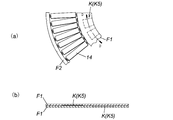
前記開放手段Kの具体的な構造例として、図4(a)および図6(a)の例では、内側のフレームF1の内縁に切り欠きK1を形成してある。かかる切り欠きK1を設けた場合と設けない場合とで比較すると、フレームF1の重ね合わせ面の接触面積は、切り欠きK1を設けた本例の方が減少しているため、フレームF1の重ね合せ部に閉じ込まれる気体や流体は本例の方が少なくなる。本例においても、切り欠きK1のない部分ではフレームF1の重ね合せ部に気体や流体が多少閉じ込まれるが、閉じ込まれた気体は切り欠きK1の切り口から速やかにフレームF1の外へ流出できる。従って、この図4(a)および図6(a)の例のような切り欠きK1を採用した排気ポンプPによると、フレームF1の重ね合せ部から気体や流体が少しずつ徐々に流出し続ける量が減ることから、排気時間の短縮を図れる。
前記開放手段Kの具体的な他の構造例としては、例えば図9(a)(b)のように内側のフレームF1に形成した穴K2や、図10(a)(b)のようにフレームF1に切削加工又はプレス加工で形成した開放溝K3、図11(a)(b)のようにフレームF1にプレスで曲げ成形した開放溝K4、あるいは図12(a)(b)のようにフレームF1に切削加工又はプレス加工で形成した窪みK5、若しくは、その切り欠きK1、穴K2、開放溝K3、K4、窪みK5の組み合わせを採用することもできる。
図9(a)(b)では、穴K2の一例として、略四角形状の穴を例示したが、この穴の形状に限定されることはなく、様々な形状の穴を採用することができる。この点については図4(a)および図6(a)の切り欠きK1や、図12(a)(b)の窪みK5も同様である。
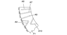
図10(a)(b)と図11(a)(b)では、開放溝K3、K4の一例として、かかる開放溝K3、K4は、ポンプ軸心を中心として放射状に設けた放射溝と、これらの放射溝に連通する連通溝とからなり、放射溝の一端がフレームF1の重ね合せ部の外に開口している形態を示したが、この形態に限定されることはない。例えば、図13のようにフレームF1の重ね合せ部の外に開口している様々な形態の開放溝K6~K10を採用することができる。
図示は省略するが、先に説明した開放手段は、必要に応じて、外側のフレームF2の重ね合せ部に設ける構成や、内外双方のフレームF1、F2に設ける構成を採用することもできる。
《翼排気部Ptによる排気動作説明》
以上の構成からなる翼排気部Ptでは、駆動モータ12の起動により、ロータ軸5、ロータ6および複数の回転翼ブレード13が一体に高速回転し、最上段の回転翼ブレード13がガス吸気口2から入射した気体分子に下向き方向の運動量を付与する。この下向き方向の運動量を有する気体分子が固定翼14によって次段の回転翼ブレード13側へ送り込まれる。
以上の構成からなる翼排気部Ptでは、駆動モータ12の起動により、ロータ軸5、ロータ6および複数の回転翼ブレード13が一体に高速回転し、最上段の回転翼ブレード13がガス吸気口2から入射した気体分子に下向き方向の運動量を付与する。この下向き方向の運動量を有する気体分子が固定翼14によって次段の回転翼ブレード13側へ送り込まれる。
以上のような気体分子への運動量の付与と送り込み動作とが繰り返し多段に行われることにより、ガス吸気口2側の気体分子はロータ6の下流に向かって順次移行するように排気される。この際、固定翼ブレード14の端部付近の空隙Gと重なるように配置された突起部Tにより、その空隙Gを抜ける気体分子の逆流(内部リーク)が防止されるので、排気速度が速くなり、排気時間の短縮を図ることができる。
《ネジ溝排気部Psの詳細構成》
ネジ溝排気部Psの詳細構成については業界周知の内容のため、説明を省略する。
ネジ溝排気部Psの詳細構成については業界周知の内容のため、説明を省略する。
《ネジ溝排気部Psにおける排気動作説明》
翼排気部Ptの排気動作による移送で最下段の翼(図1の例では回転翼ブレード)に到達した気体分子は、それらに向かって開口しているネジ溝排気通路Sの上流入口から同ネジ溝排気通路Sに移行する。移行した気体分子は、ロータ6の回転によって生じる効果、すなわち、ロータ6の外周面とネジ溝19でのドラッグ効果によって、遷移流から粘性流に圧縮されながらガス排気口3に向って移行し、最終的に図示しない補助ポンプを通じて外部へ排気される。
翼排気部Ptの排気動作による移送で最下段の翼(図1の例では回転翼ブレード)に到達した気体分子は、それらに向かって開口しているネジ溝排気通路Sの上流入口から同ネジ溝排気通路Sに移行する。移行した気体分子は、ロータ6の回転によって生じる効果、すなわち、ロータ6の外周面とネジ溝19でのドラッグ効果によって、遷移流から粘性流に圧縮されながらガス排気口3に向って移行し、最終的に図示しない補助ポンプを通じて外部へ排気される。
1 外装ケース
1A ポンプケース
1B ポンプベース
1C フランジ
2 ガス吸気口
3 ガス排気口
4 ステータコラム
5 ロータ軸
6 ロータ
7 ボス孔
9 肩部
10 ラジアル磁気軸受
10A ラジアル電磁石ターゲット
10B X軸上電磁石
10C X軸上渦電流式ギャップセンサ
11 アキシャル磁気軸受
11A アーマチュアディスク
11B アキシャル電磁石
11C アキシャル方向変位センサ
12 駆動モータ
12A 固定子
12B 回転子
13 回転翼ブレード
14 固定翼ブレード
18 ネジ溝排気部ステータ
19 ネジ溝
B1、B2 保護ベアリング
F1 固定翼ブレードの内側の固定翼ブレード根元を支持するフレーム
F2 固定翼ブレードの外側の固定翼ブレード根元を支持するフレーム
G 固定翼ブレード根元付近の空隙
K 開放手段
K1 切り欠き(開放手段)
K2 穴(開放手段)
K3、K4 開放溝(開放手段)
K5 窪み(開放手段)
M 曲げ溝
T 突起部
P 排気ポンプ
Pt 翼排気部
Ps ネジ溝排気部
S ネジ溝排気通路
1A ポンプケース
1B ポンプベース
1C フランジ
2 ガス吸気口
3 ガス排気口
4 ステータコラム
5 ロータ軸
6 ロータ
7 ボス孔
9 肩部
10 ラジアル磁気軸受
10A ラジアル電磁石ターゲット
10B X軸上電磁石
10C X軸上渦電流式ギャップセンサ
11 アキシャル磁気軸受
11A アーマチュアディスク
11B アキシャル電磁石
11C アキシャル方向変位センサ
12 駆動モータ
12A 固定子
12B 回転子
13 回転翼ブレード
14 固定翼ブレード
18 ネジ溝排気部ステータ
19 ネジ溝
B1、B2 保護ベアリング
F1 固定翼ブレードの内側の固定翼ブレード根元を支持するフレーム
F2 固定翼ブレードの外側の固定翼ブレード根元を支持するフレーム
G 固定翼ブレード根元付近の空隙
K 開放手段
K1 切り欠き(開放手段)
K2 穴(開放手段)
K3、K4 開放溝(開放手段)
K5 窪み(開放手段)
M 曲げ溝
T 突起部
P 排気ポンプ
Pt 翼排気部
Ps ネジ溝排気部
S ネジ溝排気通路
Claims (12)
- 回転可能なロータの外周面から突出した複数の回転翼ブレードと、前記ロータの外周面に向って突出した複数の固定翼ブレードとを、前記ロータの軸心に沿って交互に多段に配置してなる排気ポンプに適用可能な固定翼ブレード集合体であって、
前記複数の固定翼ブレードは、内側と外側の固定翼ブレード根元がフレームで支持されており、この支持された一の固定翼ブレードとその横隣の固定翼ブレードとの間であって、かつ前記外側又は内側の固定翼ブレード根元付近の空隙には、内側の固定翼ブレード根元を支持しているフレーム又は前記外側の固定翼ブレード根元を支持しているフレーム若しくは双方のフレームから突出した突起部が設けられた構成になっていること
を特徴とする固定翼ブレード集合体。 - 前記一の固定翼ブレードとその横隣の固定翼ブレードは、それぞれの内側及び外側の固定翼ブレード根元が同じフレームで支持されることにより、一枚構造の固定翼ブレード集合体として構成されていること
を特徴とする請求項1に記載の固定翼ブレード集合体。 - 前記一の固定翼ブレードとその横隣の固定翼ブレードは、それぞれの内側及び外側の固定翼ブレード根元が別々のフレームで支持され、これらのフレームを上下に重ね合わせて接合することにより二枚重ね構造として形成され、前記突起部が前記外側又は内側の固定翼ブレード根元付近の空隙と重なる構成となっていること
を特徴とする請求項1に記載の固定翼ブレード集合体。 - 回転可能なロータの外周面から突出した複数の回転翼ブレードと、前記ロータの外周面に向って突出した複数の固定翼ブレードとを、前記ロータの軸心に沿って交互に多段に配置してなる排気ポンプに適用可能な固定翼ブレード集合体であって、
前記複数の固定翼ブレードのうちいずれか一の固定翼ブレードとその横隣の固定翼ブレードは、それぞれの固定翼ブレード根元が別々のフレームで支持され、これらのフレームを上下に重ね合わせて接合することにより一枚の固定翼ブレード集合体として形成される構成、及び、それぞれの固定翼ブレード根元が互いにロータの径方向でずれて配置されることにより、一の固定翼ブレード根元付近における固定翼ブレード端部がその横隣の固定翼ブレード根元付近の空隙に重なる構成になっていること
を特徴とする固定翼ブレード集合体。 - 回転可能なロータの外周面から突出した複数の回転翼ブレードと、前記ロータの外周面に向って突出した複数の固定翼ブレードとを、前記ロータの軸心に沿って交互に多段に配置してなる排気ポンプに適用可能な固定翼ブレード集合体であって、
前記複数の固定翼ブレードのうちいずれか一の固定翼ブレードとその横隣の固定翼ブレードは、それぞれの固定翼ブレード根元が別々のフレームで支持され、これらのフレームを上下に重ね合わせてなるとともに、それぞれの外側又は内側の固定翼ブレード根元を支持している前記フレームどうしを接合することにより一枚の固定翼ブレード集合体として形成されていることを特徴とする固定翼ブレード集合体。 - 前記フレームの重ね合わせ部には、その重ね合わせ部に閉じ込まれている気体や流体をフレームの外へ逃がす開放手段が設けられていること
を特徴とする請求項5に記載の固定翼ブレード集合体。 - 前記開放手段は、前記フレームに形成した切り欠きからなること
を特徴とする請求項6に記載の固定翼ブレード集合体。 - 前記開放手段は、前記フレームに形成した穴からなること
を特徴とする請求項6に記載の固定翼ブレード集合体。 - 前記開放手段は、前記フレームに形成した開放溝からなること
を特徴とする請求項6に記載の固定翼ブレード集合体。 - 前記開放手段は、前記フレームに形成した窪みからなること
を特徴とする請求項6に記載の固定翼ブレード集合体。 - 前記フレームどうしの接合は、カシメ加工によるものであること
を特徴とする請求項5に記載の固定翼ブレード集合体。 - 請求項1から11記載のうちいずれか1項に記載の固定翼ブレード集合体を備えたことを特徴とする排気ポンプ。
Priority Applications (3)
| Application Number | Priority Date | Filing Date | Title |
|---|---|---|---|
| EP11847978.1A EP2653728B1 (en) | 2010-12-14 | 2011-09-13 | Fixed blade assembly usable in exhaust pump, and exhaust pump provided with same |
| JP2012548687A JP6005525B2 (ja) | 2010-12-14 | 2011-09-13 | 排気ポンプに適用可能な固定翼ブレード集合体、及びそれを備えた排気ポンプ |
| US13/990,998 US9879553B2 (en) | 2010-12-14 | 2011-09-13 | Fixed blade assembly usable in exhaust pump, and exhaust pump provided with same |
Applications Claiming Priority (2)
| Application Number | Priority Date | Filing Date | Title |
|---|---|---|---|
| JP2010-278153 | 2010-12-14 | ||
| JP2010278153 | 2010-12-14 |
Publications (1)
| Publication Number | Publication Date |
|---|---|
| WO2012081287A1 true WO2012081287A1 (ja) | 2012-06-21 |
Family
ID=46244402
Family Applications (1)
| Application Number | Title | Priority Date | Filing Date |
|---|---|---|---|
| PCT/JP2011/070800 Ceased WO2012081287A1 (ja) | 2010-12-14 | 2011-09-13 | 排気ポンプに適用可能な固定翼ブレード集合体、及びそれを備えた排気ポンプ |
Country Status (4)
| Country | Link |
|---|---|
| US (1) | US9879553B2 (ja) |
| EP (1) | EP2653728B1 (ja) |
| JP (1) | JP6005525B2 (ja) |
| WO (1) | WO2012081287A1 (ja) |
Cited By (1)
| Publication number | Priority date | Publication date | Assignee | Title |
|---|---|---|---|---|
| US20140205431A1 (en) * | 2013-01-22 | 2014-07-24 | Shimadzu Corporation | Vacuum pump |
Families Citing this family (2)
| Publication number | Priority date | Publication date | Assignee | Title |
|---|---|---|---|---|
| JP6735119B2 (ja) * | 2016-03-10 | 2020-08-05 | エドワーズ株式会社 | 真空ポンプ及びそれに使用される静翼部 |
| JP7049052B2 (ja) * | 2016-09-27 | 2022-04-06 | エドワーズ株式会社 | 真空ポンプ、および真空ポンプに備わる固定円板 |
Citations (3)
| Publication number | Priority date | Publication date | Assignee | Title |
|---|---|---|---|---|
| JPH09303288A (ja) * | 1996-05-16 | 1997-11-25 | Daikin Ind Ltd | ターボ分子ポンプの翼 |
| JP2003269365A (ja) | 2002-03-13 | 2003-09-25 | Boc Edwards Technologies Ltd | 真空ポンプ |
| JP2005337028A (ja) * | 2004-05-24 | 2005-12-08 | Shimadzu Corp | ターボ分子ポンプ |
Family Cites Families (4)
| Publication number | Priority date | Publication date | Assignee | Title |
|---|---|---|---|---|
| US4561670A (en) * | 1982-05-28 | 1985-12-31 | Honda Giken Kogyo Kabushiki Kaisha | Frame for automated two-wheel vehicles, and method for its manufacture |
| IT1241177B (it) * | 1990-02-16 | 1993-12-29 | Varian Spa | Statore per pompa turbomolecolare. |
| DE102005027097A1 (de) * | 2005-06-11 | 2006-12-14 | Pfeiffer Vacuum Gmbh | Statorscheibe für Turbomolekularpumpe |
| US7759249B2 (en) * | 2006-03-28 | 2010-07-20 | Tokyo Electron Limited | Method of removing residue from a substrate |
-
2011
- 2011-09-13 EP EP11847978.1A patent/EP2653728B1/en active Active
- 2011-09-13 US US13/990,998 patent/US9879553B2/en active Active
- 2011-09-13 JP JP2012548687A patent/JP6005525B2/ja active Active
- 2011-09-13 WO PCT/JP2011/070800 patent/WO2012081287A1/ja not_active Ceased
Patent Citations (4)
| Publication number | Priority date | Publication date | Assignee | Title |
|---|---|---|---|---|
| JPH09303288A (ja) * | 1996-05-16 | 1997-11-25 | Daikin Ind Ltd | ターボ分子ポンプの翼 |
| JP2003269365A (ja) | 2002-03-13 | 2003-09-25 | Boc Edwards Technologies Ltd | 真空ポンプ |
| JP2005337028A (ja) * | 2004-05-24 | 2005-12-08 | Shimadzu Corp | ターボ分子ポンプ |
| JP4517724B2 (ja) | 2004-05-24 | 2010-08-04 | 株式会社島津製作所 | ターボ分子ポンプ |
Non-Patent Citations (1)
| Title |
|---|
| See also references of EP2653728A4 |
Cited By (2)
| Publication number | Priority date | Publication date | Assignee | Title |
|---|---|---|---|---|
| US20140205431A1 (en) * | 2013-01-22 | 2014-07-24 | Shimadzu Corporation | Vacuum pump |
| US10161403B2 (en) * | 2013-01-22 | 2018-12-25 | Shimadzu Corporation | Vacuum pump |
Also Published As
| Publication number | Publication date |
|---|---|
| EP2653728B1 (en) | 2021-12-29 |
| EP2653728A4 (en) | 2018-04-11 |
| EP2653728A1 (en) | 2013-10-23 |
| JP6005525B2 (ja) | 2016-10-12 |
| US9879553B2 (en) | 2018-01-30 |
| JPWO2012081287A1 (ja) | 2014-05-22 |
| US20140010659A1 (en) | 2014-01-09 |
Similar Documents
| Publication | Publication Date | Title |
|---|---|---|
| JP5763660B2 (ja) | 排気ポンプ | |
| JP6208141B2 (ja) | ロータ、及び、このロータを備えた真空ポンプ | |
| US11448223B2 (en) | Vacuum pump and spiral plate, spacer, and rotating cylindrical body each included vacuum pump | |
| TW200300820A (en) | Vacuum pump | |
| JP2000274394A (ja) | ターボ分子ポンプ | |
| JP4676731B2 (ja) | ターボ分子ポンプ固定翼及び真空ポンプ | |
| CN109690089B (zh) | 真空泵以及真空泵所具备的固定圆板 | |
| JP6005525B2 (ja) | 排気ポンプに適用可能な固定翼ブレード集合体、及びそれを備えた排気ポンプ | |
| CN108708863B (zh) | 真空泵、真空泵的旋转体和静翼及其制造方法 | |
| WO2017099182A1 (ja) | 連結型ネジ溝スペーサ、および真空ポンプ | |
| JP5897005B2 (ja) | 真空ポンプとそのロータ | |
| US11466692B2 (en) | Adaptor and vacuum pump | |
| WO2018043072A1 (ja) | 真空ポンプ、および真空ポンプに備わる回転円筒体 | |
| JP2003269364A (ja) | 真空ポンプ | |
| JP2014173468A (ja) | 真空ポンプ | |
| JP2006090231A (ja) | ターボ分子ポンプ固定翼の製造方法および真空ポンプ | |
| JP6735119B2 (ja) | 真空ポンプ及びそれに使用される静翼部 | |
| JP2008280977A (ja) | ターボ分子ポンプ | |
| CN113518864A (zh) | 真空泵及用于真空泵的密封部件 |
Legal Events
| Date | Code | Title | Description |
|---|---|---|---|
| 121 | Ep: the epo has been informed by wipo that ep was designated in this application |
Ref document number: 11847978 Country of ref document: EP Kind code of ref document: A1 |
|
| WWE | Wipo information: entry into national phase |
Ref document number: 2012548687 Country of ref document: JP |
|
| WWE | Wipo information: entry into national phase |
Ref document number: 2011847978 Country of ref document: EP |
|
| WWE | Wipo information: entry into national phase |
Ref document number: 13990998 Country of ref document: US |
|
| NENP | Non-entry into the national phase |
Ref country code: DE |